LG Electronics USA 37LDBT LCD TV/Monitor User Manual MFL34797004 Edit1
LG Electronics USA LCD TV/Monitor MFL34797004 Edit1
Contents
- 1. Users Manual 1
- 2. Users Manual 2
- 3. Users Manual 3
Users Manual 2
EXTERNAL EQUIPMENT SETUP
20
VCR SETUP
EXTERNAL EQUIPMENT SETUP
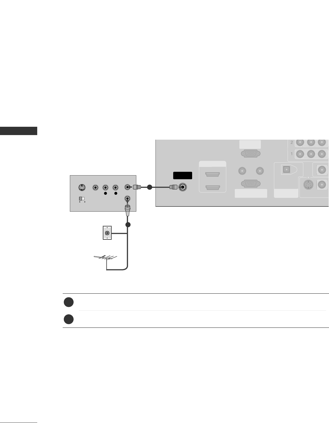
When connecting with an antenna
■To avoid picture noise (interference), leave an adequate distance between the VCR and TV
■Use the ISM feature in the Option menu to avoid having a fixed image remain on the screen for a long period
of time. If the 4:3 picture format is used; the fixed images on the sides of the screen may remain visible on
the screen. This phenomenon is common to all manufactures and in consequence the manufactures warranty
does not cover the product bearing this phenomenon.
HDMI/DVI IN
ANTENNA/
CABLE IN
REMOTE
CONTROL IN
RS-232C IN
(CONTROL & SERVICE)
RGB IN
(PC)
AUDIO IN
(RGB/DVI)
DIGITAL AUDIO
OUT
OPTICAL
1
2
VIDEO
S-VIDEO
L R
S-VIDEO VIDEO
OUTPUT
SWITCH
ANT IN
ANT OUT
VIDEO
AUDIO
( )
AUDIO
( )
Wall Jack
Antenna
1
2
Connect the RF antenna out socket of the VCR to the AAnntteennnnaasocket on the set.
Connect the antenna cable to the RF antenna in socket of the VCR.
1. How to connect
■Set VCR output switch to 3 or 4 and then tune TV to the same channel number.
■Insert a video tape into the VCR and press PLAY on the VCR. (Refer to the VCR owner’s manual.)
2. How to use
2
1
EXTERNAL EQUIPMENT SETUP
21
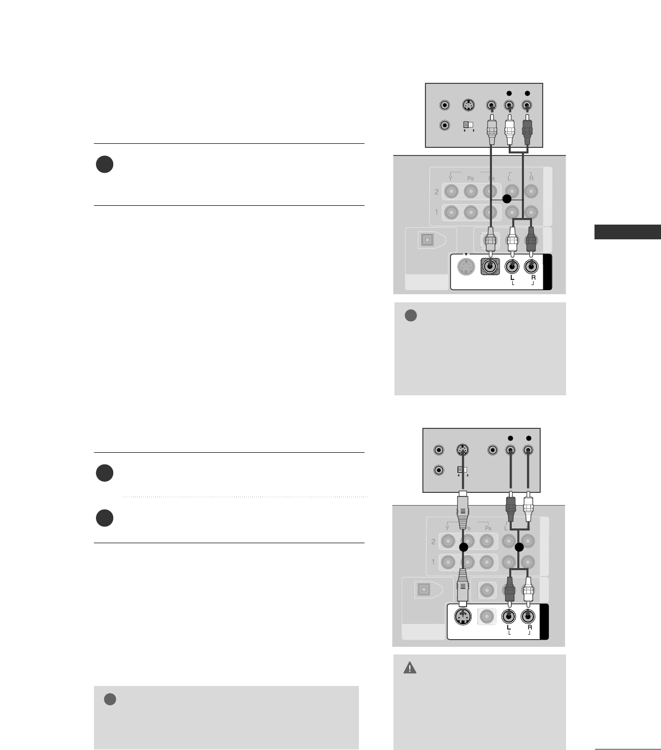
GGDo not connect to both Video
and S-Video at the same time. In
the event that you connect both
Video and the S-Video cables,
only the S-Video will work.
CAUTION
When connecting with a RCA cable
GGThe picture quality is improved: compared to normal
composite (RCA cable) input.
NOTE
!
N
DIGITAL AUDIO
OUT
OPTICAL
COMPONENT IN AV OUT
AV IN 1
S-VIDEO
VIDEO
AUDIO
VIDEO
AUDIO
MONO
( )
L R
S-VIDEO VIDEO
OUTPUT
SWITCH
ANT IN
ANT OUT
AUDIO
( )
VIDEO
AUDIO
( )
L R
S-VIDEO VIDEO
OUTPUT
SWITCH
ANT IN
ANT OUT
DIGITAL AUDIO
OUT
OPTICAL
COMPONENT IN AV OUT
VIDEO
AUDIO
AV IN 1
VIDEO
S-VIDEO AUDIO
MONO
( )
Connect the AAUUDDIIOO/VVIIDDEEOOjacks between TV and
VCR. Match the jack colors (Video = yellow, Audio Left
= white, and Audio Right = red)
1. How to connect
2. How to use
■Insert a video tape into the VCR and press PLAY on the
VCR. (Refer to the VCR owner’s manual.)
■Select AAVV11input source with using the IINNPPUUTTbutton on
the remote control.
■If connected to AAVV IINN22, select AAVV22 input source.
When connecting with an S-Video cable
Connect the S-VIDEO output of the VCR to the
SS--VVIIDDEEOO input on the set.
Connect the audio outputs of the VCR to the AAUUDDIIOO
input jacks on the set.
1. How to connect
2. How to use
■Insert a video tape into the VCR and press PLAY on the VCR.
(Refer to the VCR owner’s manual.)
■Select AAVV11input source with using the IINNPPUUTTbutton on
the remote control.
■If connected to AAVV IINN22, select AAVV22 input source.
1
2
1
GGIf you have a mono VCR, con-
nect the audio cable from the
VCR to the AAUUDDIIOO
LL//MMOONNOOjack of the set.
NOTE
!
1
12
EXTERNAL EQUIPMENT SETUP
22
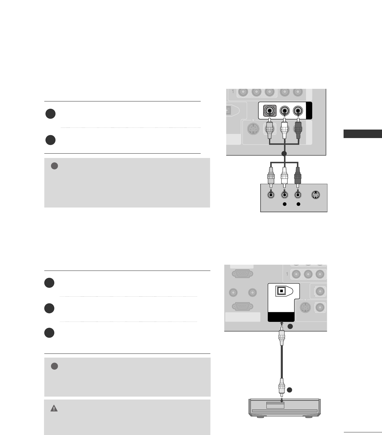
OTHER A/V SOURCE SETUP
EXTERNAL EQUIPMENT SETUP
AV IN 2
L/MONO
R
AUDIO
VIDEO
S-VIDEO
L R
VIDEO
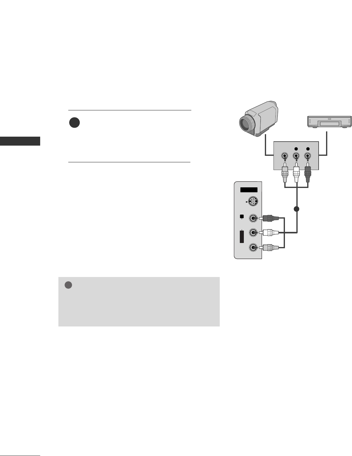
Camcorder
Video Game Set
Connect the AAUUDDIIOO/VVIIDDEEOOjacks
between TV and external equipment.
Match the jack colors
.
(Video = yellow, Audio Left = white, and
Audio Right = red)
1. How to connect
2. How to use
■Select AAVV22 input source with using the
IINNPPUUTTbutton on the remote control.
■If connected to AAVV IINN11input, select AAVV11
input source.
■Operate the corresponding external equipment.
1
1
GGThis TV finds the connected input sources automati-
cally for AV1, AV2, Component 1-2, RGB,
HDMI1/DVI and HDMI2 sources are connected.
NOTE
!
EXTERNAL EQUIPMENT SETUP
23
PC SETUP
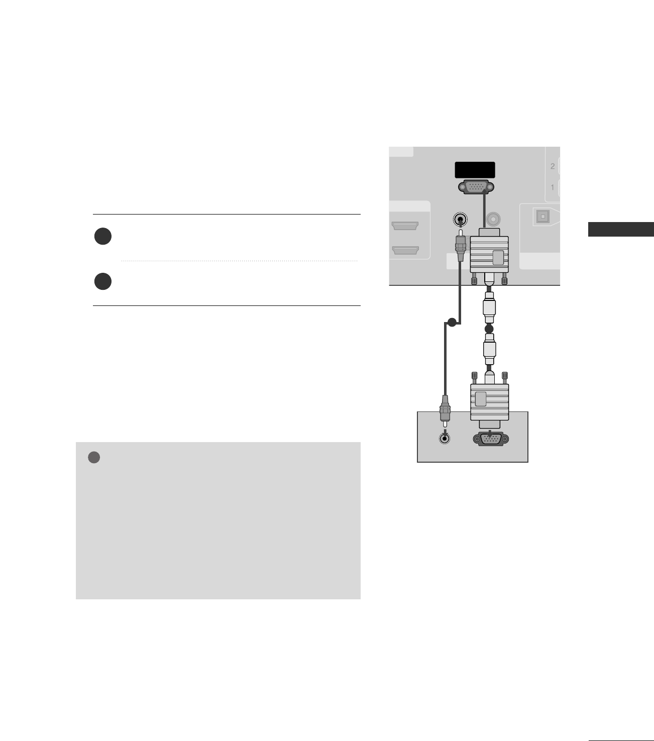
This TV provides Plug and Play capability, meaning that the PC adjusts automatically to the TV's settings.
When connecting D-sub 15pin cable
GGCheck the image on your TV. There may be noise associ-
ated with the resolution, vertical pattern, contrast or
brightness in PC mode. If noise is present, change the PC
output to another resolution, change the refresh rate to
another rate or adjust the brightness and contrast on the
VIDEO menu until the picture is clear. If the refresh rate
of the PC graphic card can not be changed, change the
PC graphic card or consult the manufacturer of the PC
graphic card.
NOTE
!
RGB OUTPUTAUDIO
HDMI/DVI IN
REMOTE
CONTROL IN
RS-232C IN
(CONTROL & SERVICE)
RGB IN
(PC)
AUDIO IN
(RGB/DVI)
DIGITAL AUDIO
OUT
OPTICAL
1
2
ERVICE
Connect the RGB output of the PC to the RRGGBB IINN
((PPCC)) jack on the set.
Connect the PC audio output to the AAUUDDIIOO IINN
((RRGGBB//DDVVII))jack on the set.
1. How to connect
2. How to use
■Turn on the PC and the set.
■Select RRGGBB--PPCCinput source in main input option of
SETUP menu. ((GG pp..6677))
2
1
1
2
EXTERNAL EQUIPMENT SETUP
24
EXTERNAL EQUIPMENT SETUP
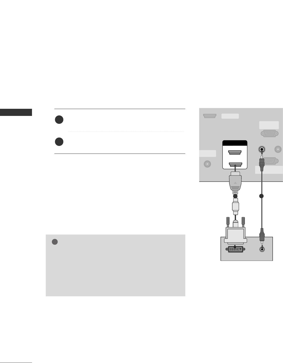
When connecting HDMI to DVI cable
ANTENNA/
CABLE IN
REMOTE
CONTROL
RS-232C IN
(CONTROL & SERVICE
RGB IN
(PC)
AUDIO IN
(RGB/DVI)
SERVICE
HDMI/DVI IN
1
2
DVI-PC OUTPUT AUDIO
12
GGIf the PC has a DVI output and no HDMI output, a sepa-
rated audio connection is necessary.
GGIf the PC does not support Auto DVI, you need to set the
output resolution appropriately. To get the best picture
quality, adjust the output resolution of PC graphics card's
output resolution to 1024x768, 60Hz.
NOTE
!
Connect the DVI output of the PC to the HHDDMMII//DDVVII
IINN 11or 22 jack on the set.
Connect the PC audio output to the AAUUDDIIOO IINN
((RRGGBB//DDVVII))jack on the set.
1. How to connect
2. How to use
■Turn on the PC and the set
■Select HHDDMMII11//DDVVIIor HHDDMMII22 input source with using
the IINNPPUUTTbutton on the remote control.
2
1
EXTERNAL EQUIPMENT SETUP
25
GGTo get the the best picture quality, adjust the PC
graphics card to 1024x768, 60Hz.
GGDepending on the graphics card, DOS mode may
not work if a HDMI to DVI Cable is in use.
GGWhen Source Devices are connected with
HDMI/DVI Input, the output PC Resolution (VGA,
SVGA, XGA, WXGA), Position and Size may not fit
on the Screen. Press the ADJUST button to adjust
the screen Position of the TV SET and contact a
PC graphics card service center.
GGWhen Source Devices connected with HDMI/DVI
Input, output TV SET Resolution (480p, 720p,
1080i, 1080p) and TV SET Display fit EIA/CEA-
861-B Specification to Screen. If not, refer to the
Manual of HDMI/DVI Source Devices or contact
your service center.
GGIf the HDMI/DVI Source Device is not connected
to the Cable or if there is a poor cable connec-
tion, "No signal" is displayed in the HDMI/DVI
Input. In this case, that Video Resolution is not
supported. If "Invalid Format" is displayed, refer to
the Source Device manual or contact your service
center.
GGAvoid keeping a fixed image on the screen for a
long period of time. The fixed image may become
permanently imprinted on the screen.
GGThe synchronization input form for Horizontal
and Vertical frequencies is separate.
NOTES
!
RGB-PC, HDMI1/DVI-PC mode
Horizontal Vertical
Frequency(KHz)Frequency(Hz)
31.469 70.08
31.469 70.08
31.469 59.94
37.879 60.31
48.363 60.00
47.776 59.87
47.720 59.799
47.130 59.65
Resolution
720x400
1360x768
640x350
* RGB-PC mode only: 640x350, 720X400
640x480
800x600
1024x768
HDMI1/DVI-DTV, HDMI2-DTV mode
Horizontal Vertical
Frequency(KHz)Frequency(Hz)
31.469 59.94
31.500 60.00
44.960 59.94
45.000 60.00
33.720 59.94
33.750 60.00
27.000 24.00
33.750 30.00
Resolution
720x480
1280x720
1920x1080i
1920x1080p
1280x768
1366x768
Supported Display Specifications
EXTERNAL EQUIPMENT SETUP
26
EXTERNAL EQUIPMENT SETUP
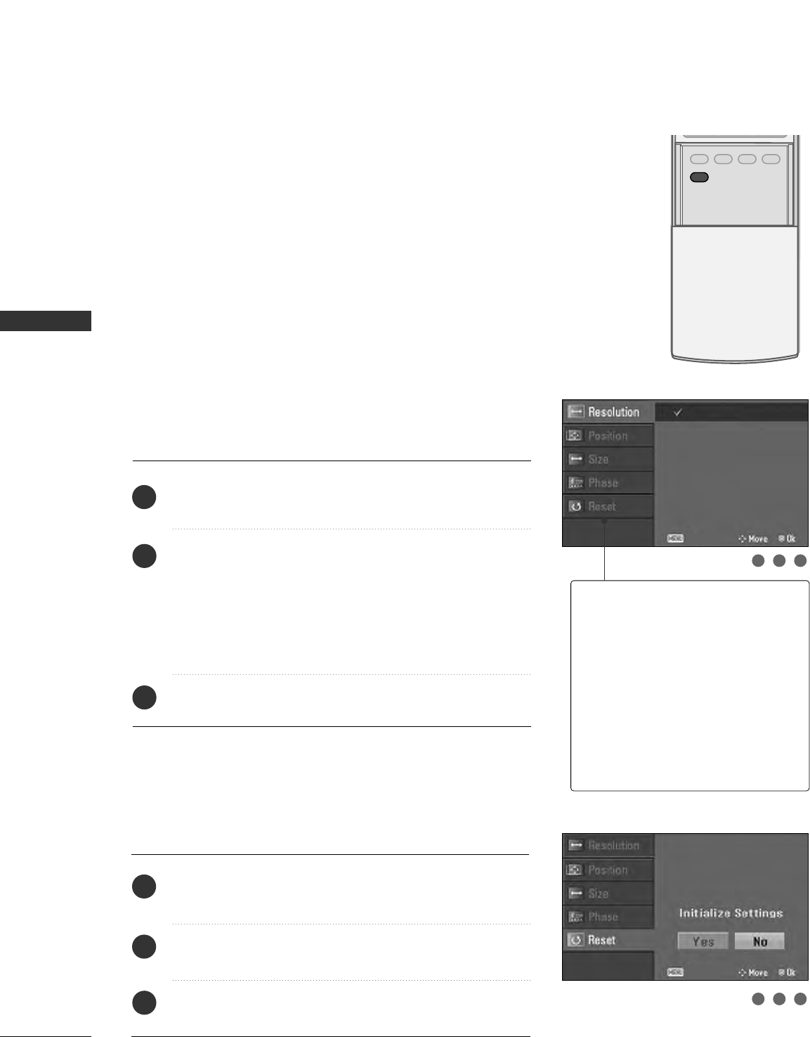
Screen Setup for PC mode
Overview
When RGB connect to PC output and select the RGB-PC in Input
source, this function is used.
When HDM/DVI connect to PC output and select HDMI/DVI input,
this function is used.
After connecting RGB-PC or HDMI/DVI to PC input and checking the
screen quality.
When you change the resolution, select the proper resolution in pre-
sent input to see the best picture appearance.
Adjustment for screen Resolution, Position, Size,
and Phase
Press the AADDJJUUSSTTbutton and then use DD or EEbutton to
select RReessoolluuttiioonn, PPoossiittiioonn, SSiizzee, or PPhhaassee.
Press the EENNTTEERRbutton and then use DD EE FFGG button to
make appropriate adjustments.
■The PPhhaasseeadjustment range is --1166 ~++1166.
In HDMI/DVI-PC mode, PPhhaassee is not available.
■The SSiizzeeadjustment range is --3300 ~++3300.
In HDMI/DVI-PC mode, SSiizzeeis not available.
Press the EENNTTEERRbutton.
Initializing (Reset to original factory values)
Press the AADDJJUUSSTTbutton and then use DD or EEbutton to
select RReesseett.
Press the EENNTTEERR button and then use FFor GG button to
select YYeess.
Press the EENNTTEERRbutton.
To initialize the adjusted values
ADJUST
SAP
SOUND
PICTURE
CC
1
2
3
1
2
3
RReessoolluuttiioonn
This function allows you select
resolution of XGA/WXGA.
PPoossiittiioonnThis function is to adjust picture to
left/right and up/down as you prefer.
SSiizzeeThis function is to minimize any ver-
tical bars or stripes visible on the
screen background. And the hori-
zontal screen size will also change.
PPhhaasseeThis function allows you to
remove any horizontal noise and
clear or sharpen the image of char-
acters.
123
123
1024 x 768
1280 x 768
1360 x 768
1366 x 768
Close
Close
EXTERNAL EQUIPMENT SETUP
27
AV OUT SETUP
The TV has a special signal output capability which allows you to hook up the second TV or monitor.
L R S-VIDEOVIDEO
L AUDIO
UT
ICAL
NT IN AV OUT
AV IN 1
VIDEO
AUDIO
MONO
( )
S-VIDEO
Connect the second TV or monitor to the TV’s AAVV OOUUTT
jacks.
See the Operating Manual of the second TV or monitor
for further details regarding that device’s input settings.
1. How to connect
GGComponent1-2, RGB-PC, HDMI1/DVI, HDMI2, DTV input
sources cannot be used for AV out.
GGWe recommend to use the AV OUT jacks for VCR recording.
NOTE
!
2
1
1
Send the TV’s audio to external audio equipment via the Digital Audio Output (Optical)port.
REMOTE
CONTROL IN
RS-232C IN
(CONTROL & SERVICE)
(PC)
AUDIO IN
(RGB/DVI)
VIDEO
S-VIDEO
DIGITAL AUDIO
OUT
OPTICAL
GGWhen connecting with external audio equipments, such as ampli-
fiers or speakers, please turn the TV speakers off. (GG pp..8844)
NOTE
!
GGDo not look into the optical output port. Looking at the
laser beam may damage your vision.
CAUTION
Connect one end of an optical cable to the TV Digital
Audio (Optical)Output port.
Connect the other end of the optical cable to the
digital audio (optical)input on the audio equipment.
Set the “TV Speaker option - Off” in the AUDIO
menu. (GGpp..8844). See the external audio equipment
instruction manual for operation.
1. How to connect
2
3
1
1
2
DIGITAL AUDIO OUTPUT
WATCHING TV / CHANNEL CONTROL
28
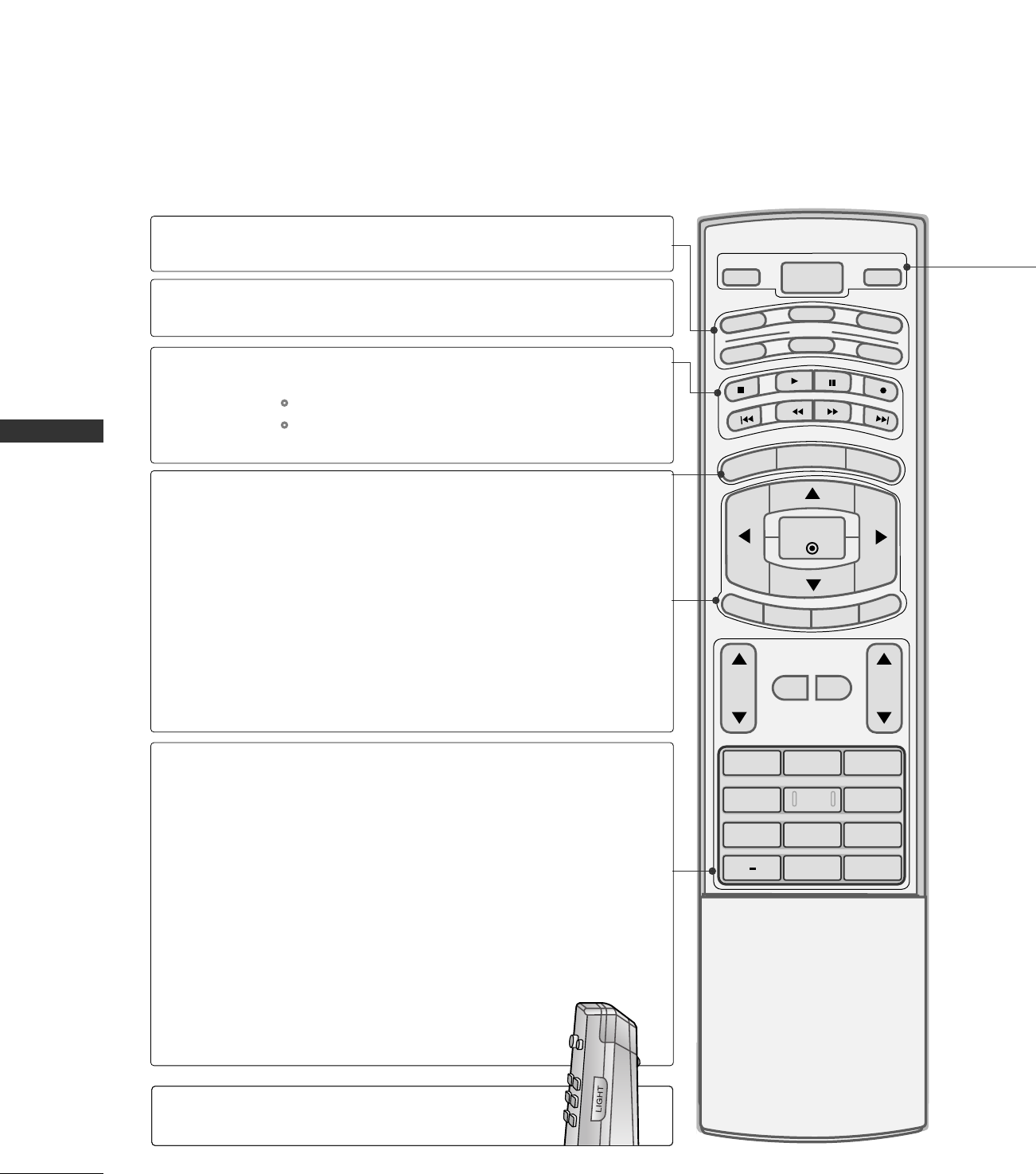
REMOTE CONTROL FUNCTIONS
WATCHING TV / CHANNEL CONTROL
1 2 3
4 5 6
78
0
9
BACK
VOL CH
MUTE
FAV
BRIGHT -
MENU
BRIGHT +
ENTER
EXIT
TIMER
RATIO
SIMPLINK
POWER
VCR
TV
DVD
AUDIO
CABLE
STB
MODE
TV INPUT
INPUT
MODE
MENU
BRIGHT -/ +
THUMBSTICK
(Up/Down/Left
Right/ENTER)
EXIT
TIMER
RATIO
SIMPLINK
VOLUME UP
/DOWN
MUTE
FAV
CHANNEL
UP/DOWN
— (DASH)
BACK
Select the remote operating mode: TV, DVD, VCR,
AUDIO, CABLE or STB.
Control video cassette recorders or DVD players.
Displays the main menu.
Adjust the brightness on screen.
It turns to the default settings brightness by changing
mode source.
Navigate the on-screen menus and adjust the system set-
tings to your preference.
Clear all on-screen displays and return to TV viewing
from any menu.
Select the amount of time before your TV turns off auto-
matically. GGpp..9900
Change the aspect ratio. GGpp..9922--9933
C? GGpp..9922--9933
Increase/decrease the sound level.
Switch the sound on or off. GGpp..3388
Scroll through the programmed Favorite channels.
Select available channels.
Used to enter a program number for multiple program
channels such as 2-1, 2-2, etc.
Tune to the last channel viewed.
VCR/DVD
control buttons
NUMBER button
When using the remote control, aim it at the remote control sensor on the TV.
Illuminates the remote control
buttons of selected mode.
LIGHT
WATCHING TV / CHANNEL CONTROL
29
ADJUST
SAP
SOUND
PICTURE
CC
1 2 3
4 5 6
78
0
9
BACK
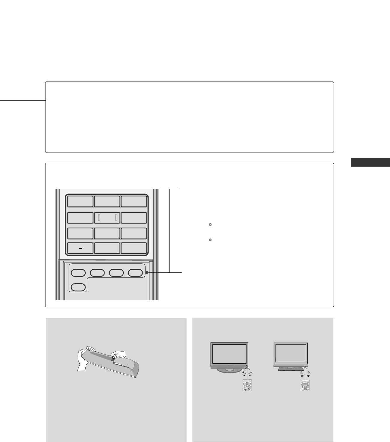
POWER
TV INPUT
INPUT
Turns your TV or any other programmed equipment on or off, depending on the mode.
In AV 1-2, Component 1-2, RGB-PC (or RGB-DTV), HDMI1/DVI, and HDMI2 input sources,
screen returns to the last TV channel.
External input modes rotate in regular sequence: Antenna, Cable, AV1-2, Component 1-2, RGB-
PC (or RGB-DTV), HDMI1/DVI and HDMI2.
(AV 1-2, Component 1-2, RGB-PC (or RGB-DTV), HDMI1/DVI, and HDMI2 input sources are
linked automatically, only if these are connected.)
PICTURE
SOUND
SAP
CC
ADJUST
Adjust the factory preset picture depend on
the viewing environment. GGpp..6699
Select the appropriate type of sound for type
of program. GGpp..8800
Analog mode: Selects MTS sound (Mono,
Stereo, and a SAP)
DTV mode: Change the audio language.
Select a closed caption. GGpp..9944
(*In DTV/CADTV mode GGpp..9955)
Adjust the screen position, size and phase in
PC mode. GGpp..
Inside the Sliding Cover
■Open the battery compartment cover on the back
side and install the batteries matching correct
polarity (+with +,-with -).
■Install two 1.5V AA batteries. Don’t mix old or
used batteries with new ones.
■Close cover.
■Use a remote control up to 7 meters distance
and 30 degree (left/right) within the receiving
unit scope.
■Dispose of used batteries in a recycle bin to
preserve environment.
BRIGHT -
MENU
BRIGHT +
POWER
VCR
TV
DVD
AUDIO
CABLE
STB
MODE
TV INPUT
INPUT
R
BRIGHT -
MENU
BRIGHT +
POWER
VCR
TV
DVD
AUDIO
CABLE
STB
MODE
TV INPUT
INPUT
Installing Batteries Remote control effective range
WATCHING TV / CHANNEL CONTROL
30
TURNING ON TV
WATCHING TV / CHANNEL CONTROL
NOTE
!
GGIf you intend to be away on vacation, disconnect the power plug from the wall power outlet.
GGWhen the TV is turned on, the indicator will blink green before the picture is seen.
First, connect power cord correctly.
At this moment, the TV switches to standby mode.
■In standby mode to turn TV on, press the , IINNPPUUTT,CCHH ((DD or EE))
button on the TV or press the PPOOWWEERR, IINNPPUUTT, TTVV IINNPPUUTT, CCHH((DD or
EE)), NNuummbbeerr ((00~99))button on the remote control.
Select the viewing source by using the TTVV IINNPPUUTT, IINNPPUUTTbutton on the
remote control.
■This TV is programmed to remember which power state it was last set
to, even if the power cord is out.
When finished using the TV, press the PPOOWWEERRbutton on the remote
control. The TV reverts to standby mode.
POWER
VCR
TV
DVD
MODE
TV INPUT INPUT
SAP
SOUND
PICTURE
CC
123
456
78
0
9
BACK
VOL CH
MUTE
FAV
EXIT
TIMER
RATIO
SIMPLINK
1
2
3
SAP
SOUND
PICTURE
CC
123
456
78
0
9
BACK
VOL CH
MUTE
FAV
EXIT
TIMER
RATIO
SIMPLINK
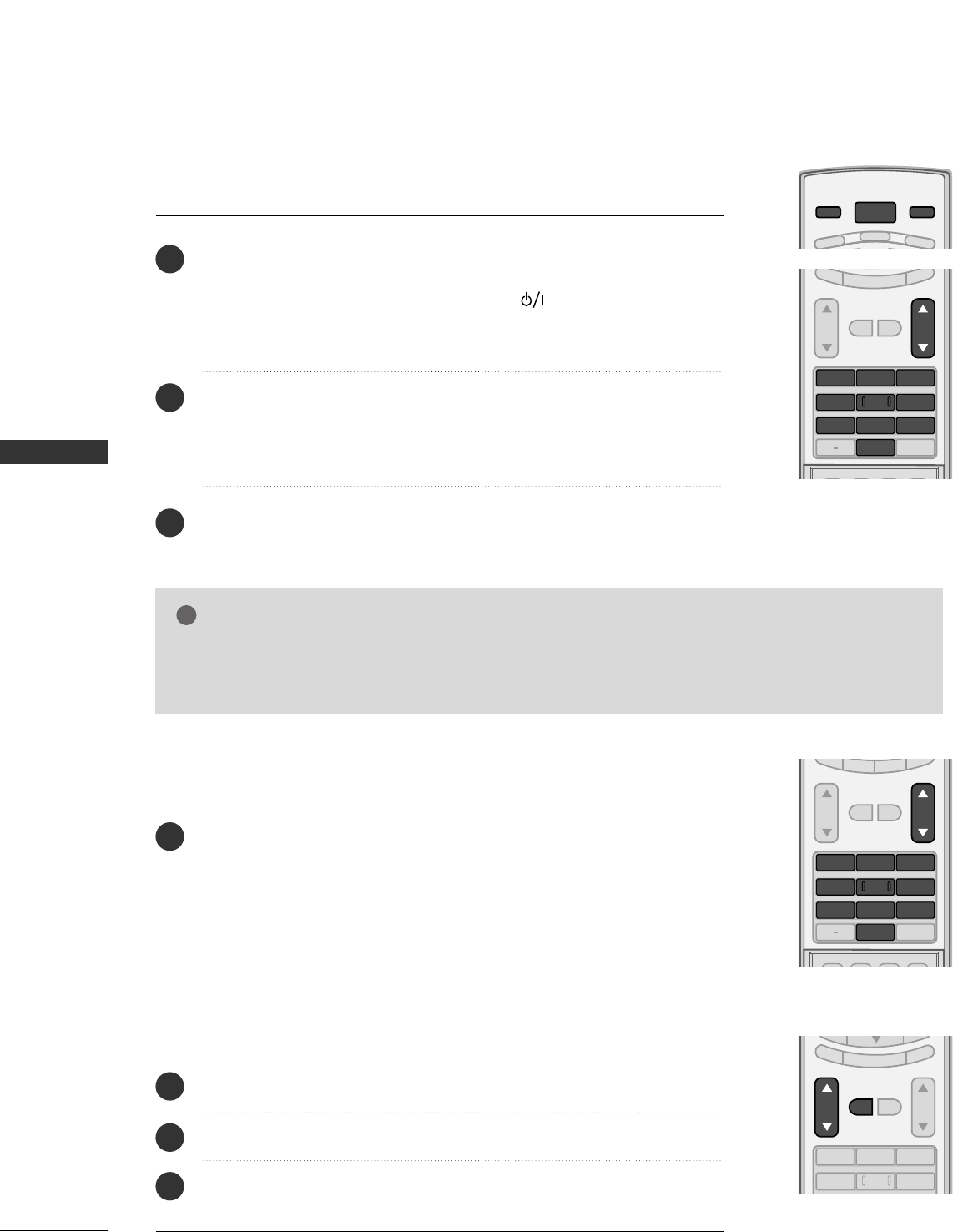
Press the CCHHDD EE or NNUUMMBBEERRbuttons to select a channel number.
1
VOLUME ADJUSTMENT
CHANNEL SELECTION
Press the VVOOLLDD or EE button to adjust the volume.
If you want to switch the sound off, press the MMUUTTEEbutton.
You can cancel the Mute function by pressing the MMUUTTEEor VVOOLLDD or EE
button.
123
456
VOL CH
MUTE
FAV
EXIT
TIMER
RATIO
SIMPLINK
Adjust the volume to suit your personal preference.
1
2
3
WATCHING TV / CHANNEL CONTROL
31
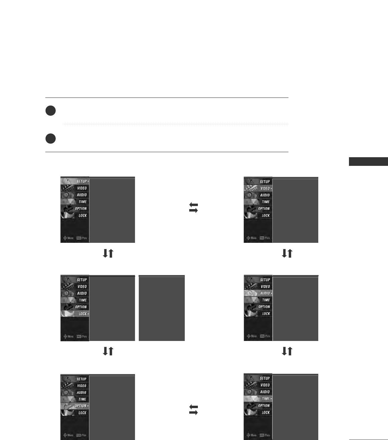
ON-SCREEN MENUS SELECTION
Press the MMEENNUUbutton and then use DD or EE button to select the each menu.
Press the GG button and then use DD EE FF GG button to display the available menus.
Your TV's OSD (On Screen Display)may differ slightly from what is shown in this manual.
SETUP VIDEO
OPTION
LOCK
TIME
EZ Scan
Manual Scan
Channel Edit
DTV Signal
Input Source
Input Label
Set ID
EZ Picture
Color Temperature
XD
Advanced
Video Reset
Auto Clock
Manual Clock
Off Timer
On Timer
Sleep Timer
Auto Off
Aspect Ratio
Caption/Text
Caption Option
Language
ISM Method
Low Power
AUDIO
Audio Language
EZ Sound
Balance
TV Speaker
Lock System
Set Password
Block Channel
Movie Rating
TV Rating-Children
TV Rating-General
Input Block
2
1
Lock System
Set Password
Block Channel
TV Rating-English
TV Rating-French
Input Block
For USA For Canada
WATCHING TV / CHANNEL CONTROL
32
AUTO SCAN (EZ SCAN)
WATCHING TV / CHANNEL CONTROL
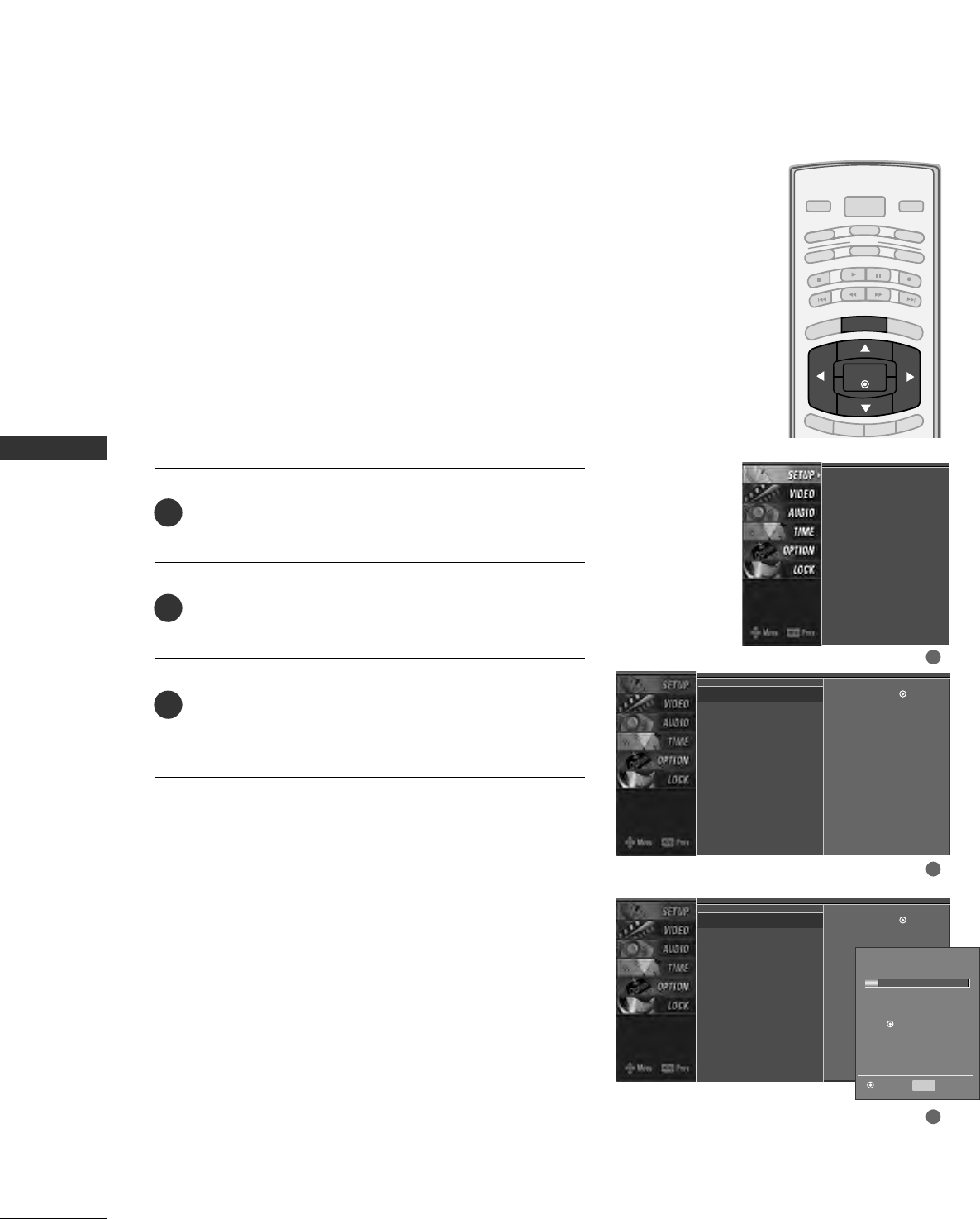
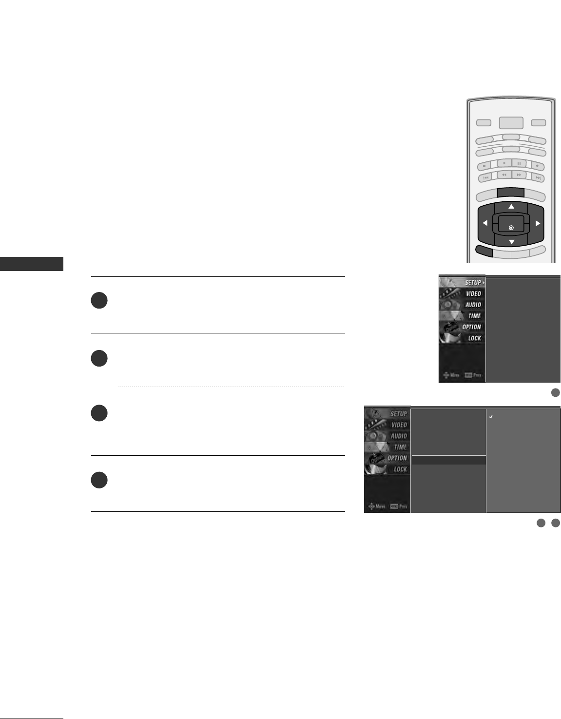
Press the MMEENNUUbutton and then use DD or EE button
to select the SSEETTUUPPmenu.
Press the GG button and then use DD or EE button to
select EEZZ SSccaann.
Press the EENNTTEERRbutton to begin the channel search.
Allow EEZZ SSccaannto complete the channel search cycle
for AANNTTEENNNNAAand CCAABBLLEE.
Automatically finds all channels available through antenna
or cable inputs, and stores them in memory on the channel
list.
Run EZ Scan again after any Antenna/Cable connection
changes.
A password is required to gain access to EZ Scan menu if
the Lock System is turned on.
EZ Scan
Manual Scan
Channel Edit
DTV Signal
Input Source
Input Label
Set ID
EZ Scan G
Manual Scan
Channel Edit
DTV Signal
Input Source
Input Label
Set ID
Selection ( Gor )
leads you to the EZ
scan screen.
EZ Scan G
Manual Scan
Channel Edit
DTV Signal
Input Source
Input Label
Set ID
Selection ( Gor )
leads you to the EZ
scan screen.
2
3
1
Processing EZ scan...
ANTENNA Ch.20
0 channel(s) found
Press to stop the
current scan and start
DIGITAL ANTENNA channel
scan.
MENU Previous
Next
1
2
3
BRIGHT -
BRIGHT +
ENTER
TIMER
RATIO
SIMPLINK
POWER
VCR
TV
DVD
AUDIO
CABLE
STB
MODE
TV INPUT INPUT
EXIT
MENU
WATCHING TV / CHANNEL CONTROL
33
ADD/DELETE CHANNEL (MANUAL SCAN)
A password is required to gain access to Manual Scan
menu if the Lock System is turned on.
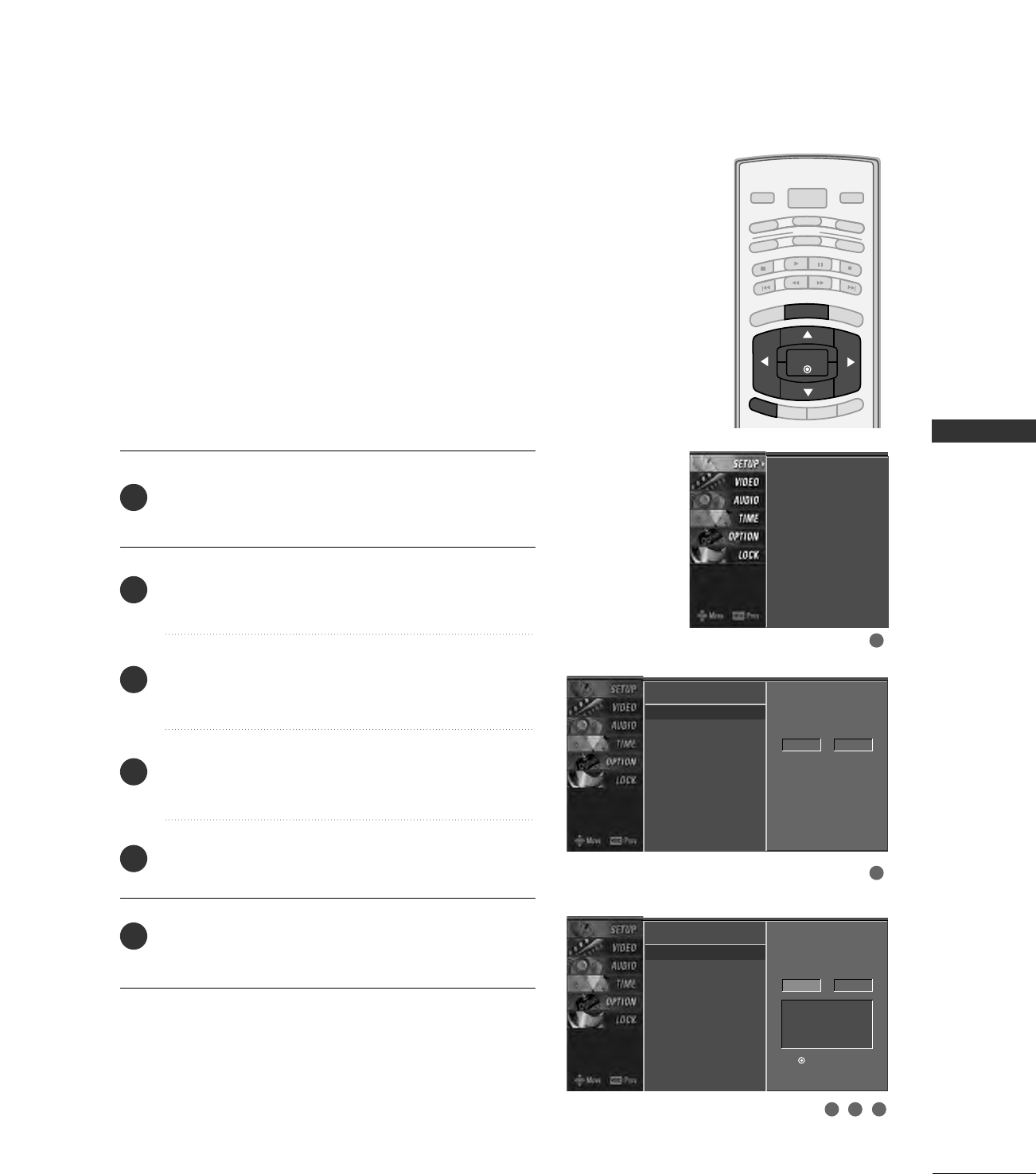
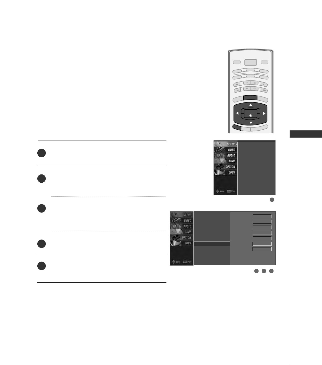
Press the MMEENNUUbutton and then use DD or EE button
to select the SSEETTUUPPmenu.
Press the GG button and then use DD or EE button to
select MMaannuuaall SSccaann.
Press the GG button and then use DD or EE button to
select TTVV, DDTTVV, CCAATTVV, and CCAADDTTVV.
Press the GG button and then use DD or EE button to
select channel you want to add or delete.
Press the EENNTTEERRbutton to add or delete the channel.
Press the EEXXIITTbutton to return to TV viewing or press
MMEENNUUbutton to return to the previous menu.
BRIGHT -
BRIGHT +
ENTER
TIMER
RATIO
SIMPLINK
POWER
VCR
TV
DVD
AUDIO
CABLE
STB
MODE
TV INPUT INPUT
EXIT
MENU
EZ Scan
Manual Scan G
Channel Edit
DTV Signal
Input Source
Input Label
Set ID
Select channel type and
RF-channel number.
TV 2
EZ Scan
Manual Scan
Channel Edit
DTV Signal
Input Source
Input Label
Set ID
EZ Scan
Manual Scan
Channel Edit
DTV Signal
Input Source
Input Label
Set ID
2
1
4
3
6
5
Select channel type and
RF-channel number.
TV GG2
Press
to delete the channel.
TV 2-0
DD
EE
1
2
3 4 5
WATCHING TV / CHANNEL CONTROL
34
CHANNEL EDITING
WATCHING TV / CHANNEL CONTROL
There are two different ways in order to add or delete
scanned channels. One is "Custom List" and the other is
"Favorite List" in the channel list. Both of them are available
after EZ Scan on the SETUP menu.
A Custom List can be created by toggling each channel on
or off with ENTER button. The channels in the Custom List
are displayed in black color, and the channels deleted from
the Custom List are displayed in gray color. Once a channel
is highlighted you can add or delete the channel by referring
to the small window at the top-left corner of the screen.
You can create your own Favorite List. Use the FFAAVVbutton
on the remote control when a channel is highlighted and
then add or delete the channel to/from your Favorite List.
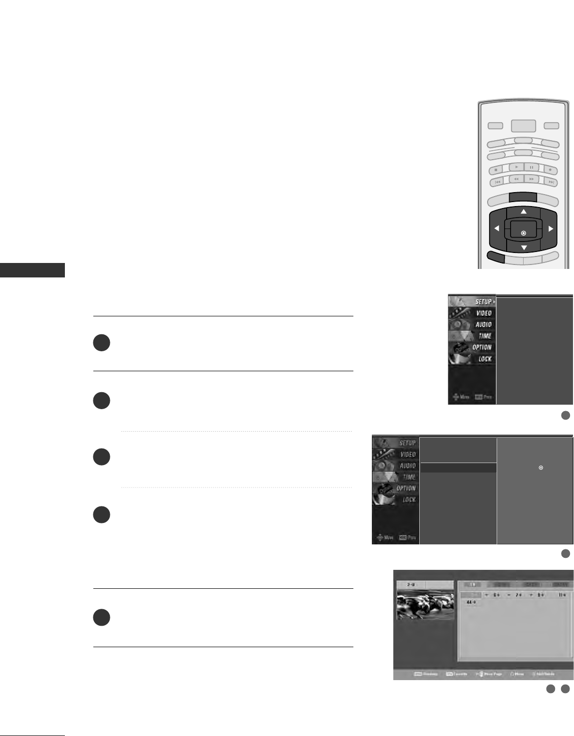
Press the MMEENNUUbutton and then use DD or EE button
to select the SSEETTUUPPmenu.
Press the GG button and then use DD or EE button to
select CChhaannnneell EEddiitt.
Press the GG button. You will now see a screen filled
with channel numbers and a preview picture.
Use DD EE FFGG button to select a channel and then
use the EENNTTEERRbutton to add or delete it.
Press FFAAVVbutton to add the channel to the Favorite List.
The heart-mark will appear in front of that channel
number.
Press EEXXIITTbutton to return to TV viewing or press
MMEENNUUbutton to return to the previous menu.
BRIGHT -
BRIGHT +
ENTER
TIMER
RATIO
SIMPLINK
POWER
VCR
TV
DVD
AUDIO
CABLE
STB
MODE
TV INPUT INPUT
EXIT
MENU
EZ Scan
Manual Scan
Channel Edit G
DTV Signal
Input Source
Input Label
Set ID
Selection ( Gor ) leads
you to the channel edit
screen.
EZ Scan
Manual Scan
Channel Edit
DTV Signal
Input Source
Input Label
Set ID
2
1
4
3
5
1
2
3 4
WATCHING TV / CHANNEL CONTROL
35
DTV SIGNAL STRENGTH
This feature displays the DTV signal levels being received
and indicates whether you need to adjust your antenna or
digital cable input. The higher the signal strength, the less
likely you are to experience picture degradation.
DTV Signal: This function is only available when the input
signal is DTV or CADTV.
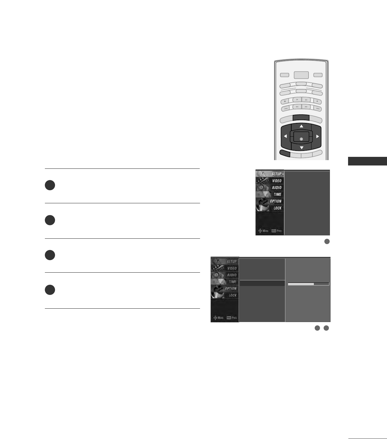
Press the MMEENNUUbutton and then use DD or EE button
to select the SSEETTUUPPmenu.
Press the GG button and then use DD or EE button to
select DDTTVV SSiiggnnaall..
View the on-screen signal strength monitor to see
the quality of the signal being received.
Press EEXXIITTbutton to return to TV viewing or press
MMEENNUUbutton to return to the previous menu.
BRIGHT -
BRIGHT +
ENTER
TIMER
RATIO
SIMPLINK
POWER
VCR
TV
DVD
AUDIO
CABLE
STB
MODE
TV INPUT INPUT
EXIT
MENU
EZ Scan
Manual Scan
Channel Edit
DTV Signal
Input Source
Input Label
Set ID
Bad Normal Good
EZ Scan
Manual Scan
Channel Edit
DTV Signal
Input Source
Input Label
Set ID
2
3
4
1
1
2 3
WATCHING TV / CHANNEL CONTROL
36
INPUT SOURCE SELECTION
WATCHING TV / CHANNEL CONTROL
Changes the picture source so you can watch your off-air
TV, cable TV, VCR, DVD, or any other devices that are con-
nected to your TV.
Press the MMEENNUUbutton and then use DD or EE button
to select the SSEETTUUPPmenu.
Press the GG button and then use DD or EE button to
select IInnppuutt SSoouurrccee..
Press the GG button and then use DD or EE button to
select the source: TTVV, AAVV11, AAVV22, CCoommppoonneenntt11,
CCoommppoonneenntt22, RRGGBB--PPCC, HHDDMMII11//DDVVII, or HHDDMMII22.
Press EEXXIITTbutton to return to TV viewing or press
MMEENNUUbutton to return to the previous menu.
EZ Scan
Manual Scan
Channel Edit
DTV Signal
Input Source G
Input Label
Set ID
TV
AV1
AV2
Component1
Component2
RGB-PC
HDMI1/DVI
HDMI2
EZ Scan
Manual Scan
Channel Edit
DTV Signal
Input Source
Input Label
Set ID
2
3
4
1
1
2 3
BRIGHT -
BRIGHT +
ENTER
TIMER
RATIO
SIMPLINK
POWER
VCR
TV
DVD
AUDIO
CABLE
STB
MODE
TV INPUT INPUT
EXIT
MENU
WATCHING TV / CHANNEL CONTROL
37
INPUT LABEL
Sets a label to each input source which is not in use when
you press the INPUT button.
Press the MMEENNUUbutton and then use DD or EE button
to select the SSEETTUUPPmenu.
Press the GG button and then use DD or EE button to
select IInnppuutt LLaabbeell.
Press the GG button and then use DD or EE button to
select the source: AAVV11, AAVV22,CCoommppoonneenntt11,
CCoommppoonneenntt22, RRGGBB--PPCC, HHDDMMII11//DDVVIIor HHDDMMII22.
Press the FF or GG button to select the label.
Press EEXXIITTbutton to return to TV viewing or press
MMEENNUUbutton to return to the previous menu.
EZ Scan
Manual Scan
Channel Edit
DTV Signal
Input Source
Input Label G
Set ID
AV1 Cable Box
AV2 VCR
Component1 DVD
Component2 Set Top Box
RGB-PC PC
HDMI1/DVI Game
HDMI2 Satellite
EZ Scan
Manual Scan
Channel Edit
DTV Signal
Input Source
Input Label
Set ID
2
3
4
5
1
1
3 42
BRIGHT -
BRIGHT +
ENTER
TIMER
RATIO
SIMPLINK
POWER
VCR
TV
DVD
AUDIO
CABLE
STB
MODE
TV INPUT INPUT
EXIT
MENU
WATCHING TV / CHANNEL CONTROL
38
WATCHING TV / CHANNEL CONTROL
This Enables you to control and play other AV devices con-
nected to TV through HDMI cable without additional cables
and settings.
In order to control AV devices connected to TV without
Simplink, user had to switch the input mode of TV and use
additional remote control bundled to the AV devices.
Simplink provides an easy solution to control all connected
devices with one remote control.
123
456
VOL CH
MUTE
FAV
BRIGHT -
MENU
BRIGHT +
ENTER
EXIT
TIMER
RATIO
SIMPLINK
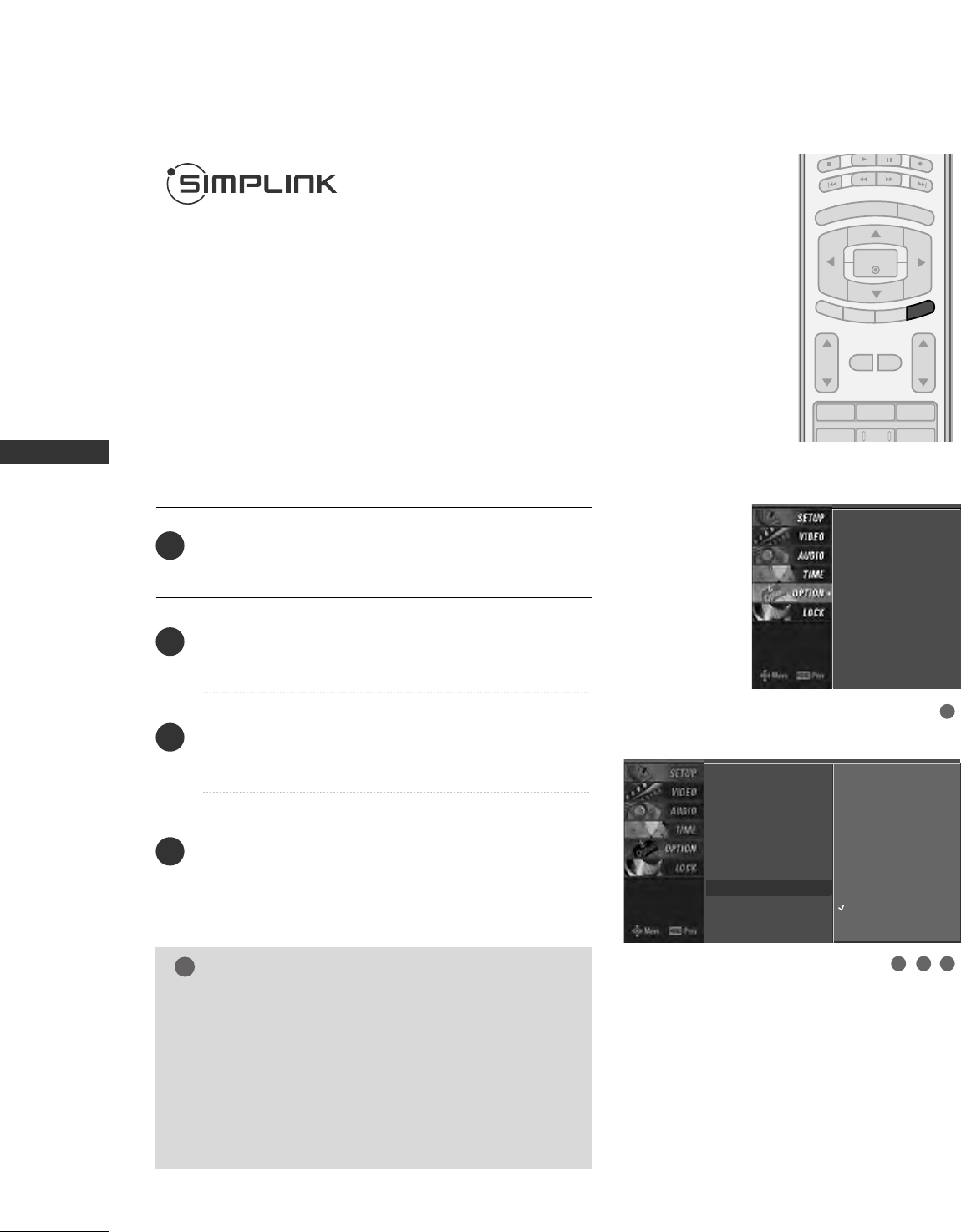
Press the MMEENNUUbutton and then use DD or EE button
to select the OOPPTTIIOONNmenu.
Press the GG button and then use DD or EEbutton to
select SSiimmppLLiinnkk.
Press the GG button and then use DD or EEbutton to
select OOnnor OOffff.
Press EEXXIITTbutton to return to TV viewing or press
MMEENNUUbutton to return to the previous menu.
NOTE
!
GGWhile Auto Tuning is proceeding, Simplink does not
work.
GGExcept Auto Tuning, Simplink stops the current activity
or clears Display OSD on the screen. After Simplink
workes, only Info. OSD resumes the display.
GGWhile Menu, XSTUDIO is proceeding, Simplink does
not work.
2
3
4
1
2 3 4
1
Aspect Ratio
Caption/Text
Caption Option
Language
ISM Method
Low Power
SimpLink
Aspect Ratio
Caption/Text
Caption Option
Language
ISM Method
Low Power
SimpLink GOff
On
WATCHING TV / CHANNEL CONTROL
39
AV devices supporting SimpLink
■DDVVDD PPllaayyeerr HH//TT : DVD player embeddedH/T device.
■HHDDDD eemmbbeeddddeedd DDVVDD RReeccoorrddeerr ((RRHH)) : DVD recorder with HDD.
■DDVVDD RReeccoorrddeerr CCoommbboo((RR--CCoommbbii)) : DVD Recorder integrating VCR.
■DDVVDD PPllaayyeerr : Pre-recorded discs playback only.
■
RReeccoorrddiinngg//DDiisscc ppllaayybbaacckk ::Control connected AV devices by pressing the
DD EE FF GG
, EENNTTEERR
buttons and buttons for play, stop, pause, fast reverse, fast forward, chapter skip.
■
DDiirreecctt PPllaayy ::After connecting AV devices to TV, you can directly control the devices and play
media without additional settings.
■
SSeelleecctt AAVV ddeevviiccee ::Enables you to select one of AV devices connected to TV and play it.
■
PPoowweerr ooffff aallll ddeevviicceess ::When you power off TV, all connected devices are turned off.
■
SSwwiittcchh aauuddiioo--oouutt ::Offers an easy way to switch audio-out.
(A device, which is connected to TV through HDMI cable but does not support Simplink, does
not provide this function)
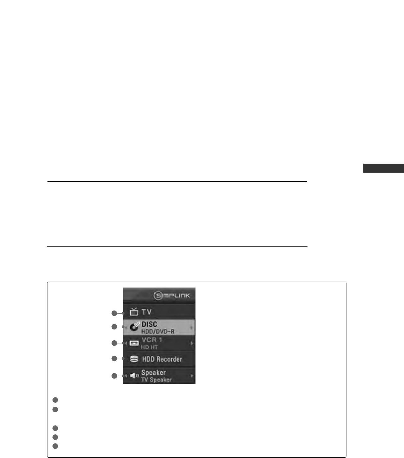
SimpLink Menu
TTVV vviieewwiinngg: Switch to the previous TV channel regardless of the current mode.
DDIISSCC ppllaayybbaacckk: Select and play connected discs.
When multiple discs are available, the titles of discs are conveniently displayed at the bottom of the screen.
VVCCRR ppllaayybbaacckk: Play and control the connected VCR.
HHDDDD RReeccoorrddiinnggss ppllaayybbaacckk: Play and control recordings stored in HDD.
AAuuddiioo OOuutt ttoo HHoommee tthheeaattrree//AAuuddiioo OOuutt ttoo TTVV: Select Home theatre or TV speaker for Audio Out.
Simplink Functions
1
2
3
4
5
GG
Selected Device
GG
When no device is connected
(displayed in gray)
GG
When a device is connected
(displayed in bright color)
1
2
3
4
5