LG Electronics USA 3G1XOUTBTS STAREX-IS 1900 Outdoor BTS User Manual STAREX IS User s Manual
LG Electronics USA STAREX-IS 1900 Outdoor BTS STAREX IS User s Manual
Contents
- 1. Users Manual Part 1
- 2. Users Manual Part 2
- 3. Users Manual Part 3
- 4. Users Manual Part 4
- 5. Users Manual Part 5
Users Manual Part 2
STAREX-IS BSM Manual
Page:318(877)
Issue:1.
0
SMD-011-PMA210
4.3.6. Network Parameter Information Change
(Change_Parameter_Info_3)
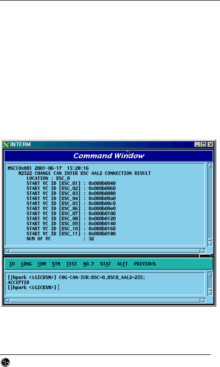
4.3.6.1. CAN INTER BSC AAL2 Setting Information Change
• Command CHG-CAN-IUR: BSC=a, [BSC0_AAL2=b], [BSC1_AAL2=c],
[BSC2_AAL2=d], [BSC3_AAL2=e], [BSC4_AAL2=f],
[BSC5_AAL2=g], [BSC6_AAL2=h], [BSC7_AAL2=i],
[BSC8_AAL2=j],[BSC9_AAL2=k],[BSC10_AAL2=l],
[BSC11_AAL2=m], [NO_AAL2_VC=n];
• Input CHG-CAN-IUR: BSC=0, BSC0_AAL2=255
• Output
STAREX-IS BSM Manual
Page:319(877)
Issue:1.
0
SMD-011-PMA210
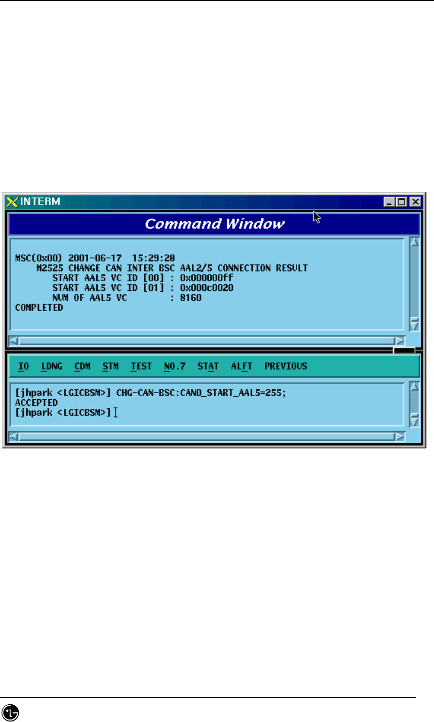
4.3.6.2. CAN INTER BSC AAL5 Setting Information Change
• Command CHG-CAN-BSC: [CAN0_START_AAL5=a],
[CAN1_START_AAL5=b], [NO_AAL5_VC=0~],
a ,b: 0~0xffffff
c: 0~
• Input CHG-CAN-BSC: CAN0_START_AAL5=255
• Output
STAREX-IS BSM Manual
Page:320(877)
Issue:1.
0
SMD-011-PMA210
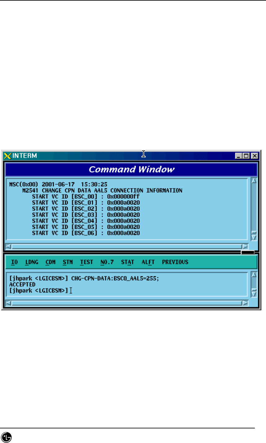
4.3.6.3. CPN INTER DATA AAL5 Setting Information Change
• Command CHG-CPN-DATA: [BSC0_AAL5=a], [BSC1_AAL5=b], [BSC2_AAL5=c],
[BSC3_AAL5=d], [BSC4_AAL5=e], [BSC5_AAL5=f],
[BSC6_AAL5=g], [BSC7_AAL5=h], [BSC8_AAL5=i],
[BSC9_AAL5=j], [BSC10_AAL5=k], [BSC11_AAL5=l],
[NO_AAL5_VC=m];
a ~n: BSC AAL5 (32~0xffffff)
m: 0~32
• Input CHG-CPN-DATA: BSC0_AAL5=255;
• Output
STAREX-IS BSM Manual
Page:321(877)
Issue:1.
0
SMD-011-PMA210
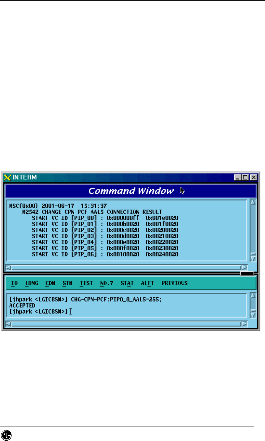
4.3.6.4. CPN INTER PCF AAL5 Setting Information Change
• Command CHG-CPN-PCF: [PIP0_0_AAL5=a], [PIP0_1_AAL5=b], [PIP1_0_AAL5=c],
[PIP1_1_AAL5=d], [PIP2_0_AAL5=e], [PIP2_1_AAL5=f],
[PIP3_0_AAL5=g], [PIP3_1_AAL5=h], [PIP4_0_AAL5=i],
[PIP4_1_AAL5=j], [PIP5_0_AAL5=k], [PIP5_1_AAL5=l],
[PIP6_0_AAL5=m], [PIP6_1_AAL5=n], [PIP7_0_AAL5=o],
[PIP7_1_AAL5=p], [PIP8_0_AAL5=q], [PIP8_1_AAL5=r],
[PIP9_0_AAL5=s], [PIP9_1_AAL5=t], [PIP10_0_AAL5=u],
[PIP10_1_AAL5=v], [NO_AAL5_VC=w]
a~v: PIP AAL5 (32~0xffffff)
w: 0~480
• Input CHG-CPN-PCF: PIP0_0_AAL5=255 ;
• Output
STAREX-IS BSM Manual
Page:322(877)
Issue:1.
0
SMD-011-PMA210
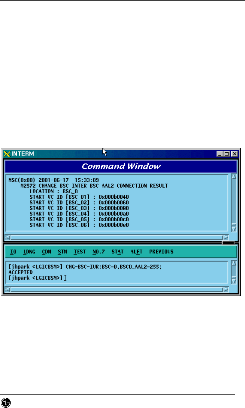
4.3.6.5. BSC INTER BSC AAL2 Setting Information Change
• Command CHG-BSC-IUR: BSC=a, [BSC0_AAL2=b], [BSC1_AAL2=c],
[BSC2_AAL2=d],
[BSC3_AAL2=e], [BSC4_AAL2=f], [BSC5_AAL2=g],
[BSC6_AAL2=h], [BSC7_AAL2=i], [BSC8_AAL2=j],
[BSC9_AAL2=k], [BSC10_AAL2=l], [BSC11_AAL2=m],
[NO_AAL2_VC=n];
a : BSC Number(0~11)
b~m: BSC AAL2 (0~0xffffff)
n: 0~
• Input CHG-BSC-IUR: BSC=0, BSC0_AAL2=255;
• Output
STAREX-IS BSM Manual
Page:323(877)
Issue:1.
0
SMD-011-PMA210
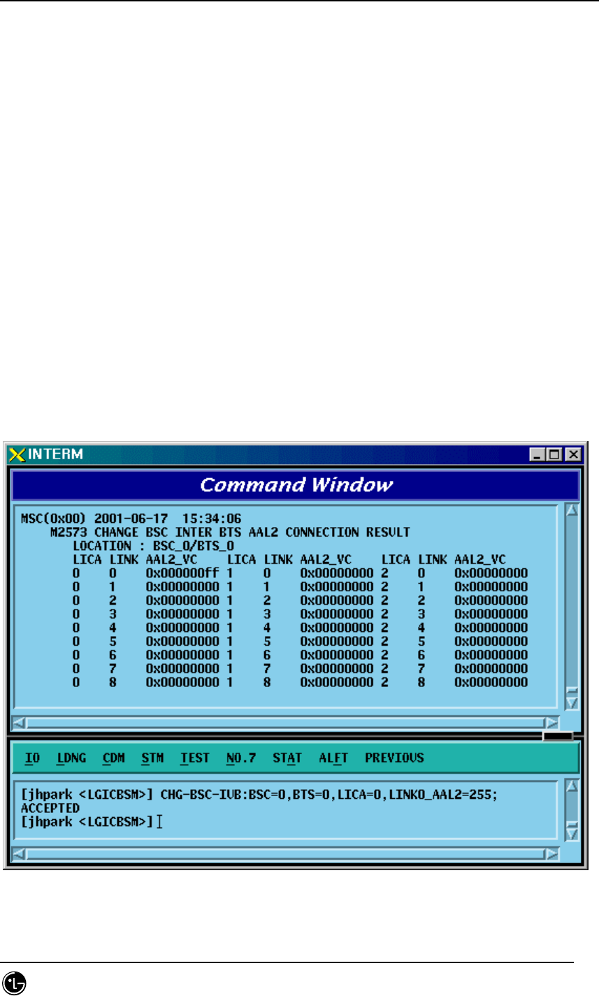
4.3.6.6. BSC INTER BTSC AAL2 Setting Information Change
• Command CHG-BSC-IUB: BSC=a, BTS=b, LICA=c, LINK=d,
[LINK0_AAL2=e], [LINK1_AAL2=f], [LINK2_AAL2=g],
[LINK3_AAL2=h], [LINK4_AAL2=i], [LINK5_AAL2=j],
[LINK6_AAL2=k], [LINK7_AAL2=l], [LINK8_AAL2=m],
[LINK9_AAL2=n], [LINK10_AAL2=o], [LINK11_AAL2=p],
[LINK12_AAL2=q], [LINK13_AAL2=r], [LINK14_AAL2=s],
[LINK15_AAL2=t]
a : BSC Number(0~11)
b : BTS Number(0~47)
c : LICA Number(0~2)
d : LINK Number(0~15)
e~t: 0~0xffffff
• Input CHG-BSC-IUB: BSC=0, BTS=0, LICA=0, LINK0_AAL2=255;
• Output
STAREX-IS BSM Manual
Page:324(877)
Issue:1.
0
SMD-011-PMA210
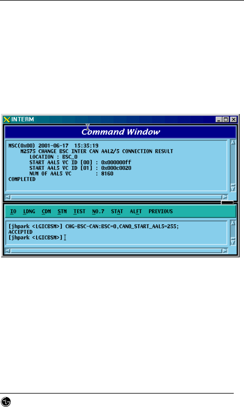
4.3.6.7. BSC INTER CAN AAL2/5 Setting Information Change
• Command CHG-BSC-CAN: BSC=a, [CAN0_START_AAL5=b],
[CAN1_START_AAL5=c], [NO_AAL5_VC=d]
a: BSC Number(0~11)
b,c: 32~0xffffff
d: 0~8160
• Input CHG-BSC-CAN: BSC=0, CAN0_START_AAL5=255;
• Output
STAREX-IS BSM Manual
Page:325(877)
Issue:1.
0
SMD-011-PMA210
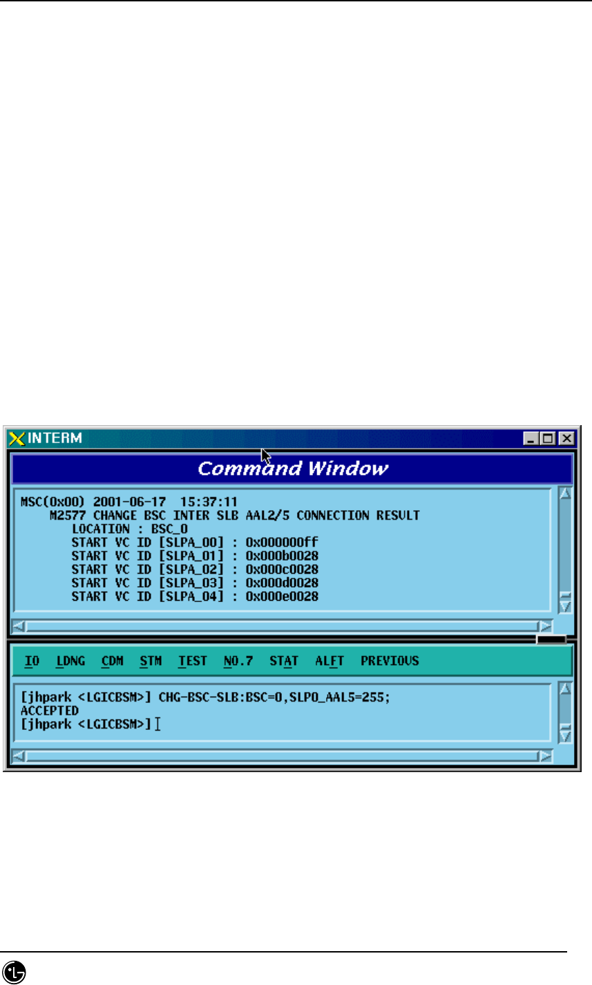
4.3.6.8. BSC INTER SLB AAL5 Setting Information
• Command CHG-BSC-SLB: BSC=a, [SLP0_AAL5=b], [SLP1_AAL5=c],
[SLP2_AAL5=d],
[SLP3_AAL5=e], [SLP4_AAL5=f], [SLP5_AAL5=g],
[SLP6_AAL5=h], [SLP7_AAL5=i], [SLP8_AAL5=j],
[SLP9_AAL5=k], [SLP10_AAL5=l], [SLP11_AAL5=m],
[SLP12_AAL5=n], [SLP13_AAL5=o], [SLP14_AAL5=p],
[SLP15_AAL5=q], [SLP16_AAL5=r], [SLP17_AAL5=s],
[NO_AAL5_VC=t]
a: BSC Number(0~11)
b~s: 40~0xffffff
t: 0~984
• Input CHG-BSC-SLB: BSC=0, SLP0_AAL5=255;
• Output
STAREX-IS BSM Manual
Page:326(877)
Issue:1.
0
SMD-011-PMA210
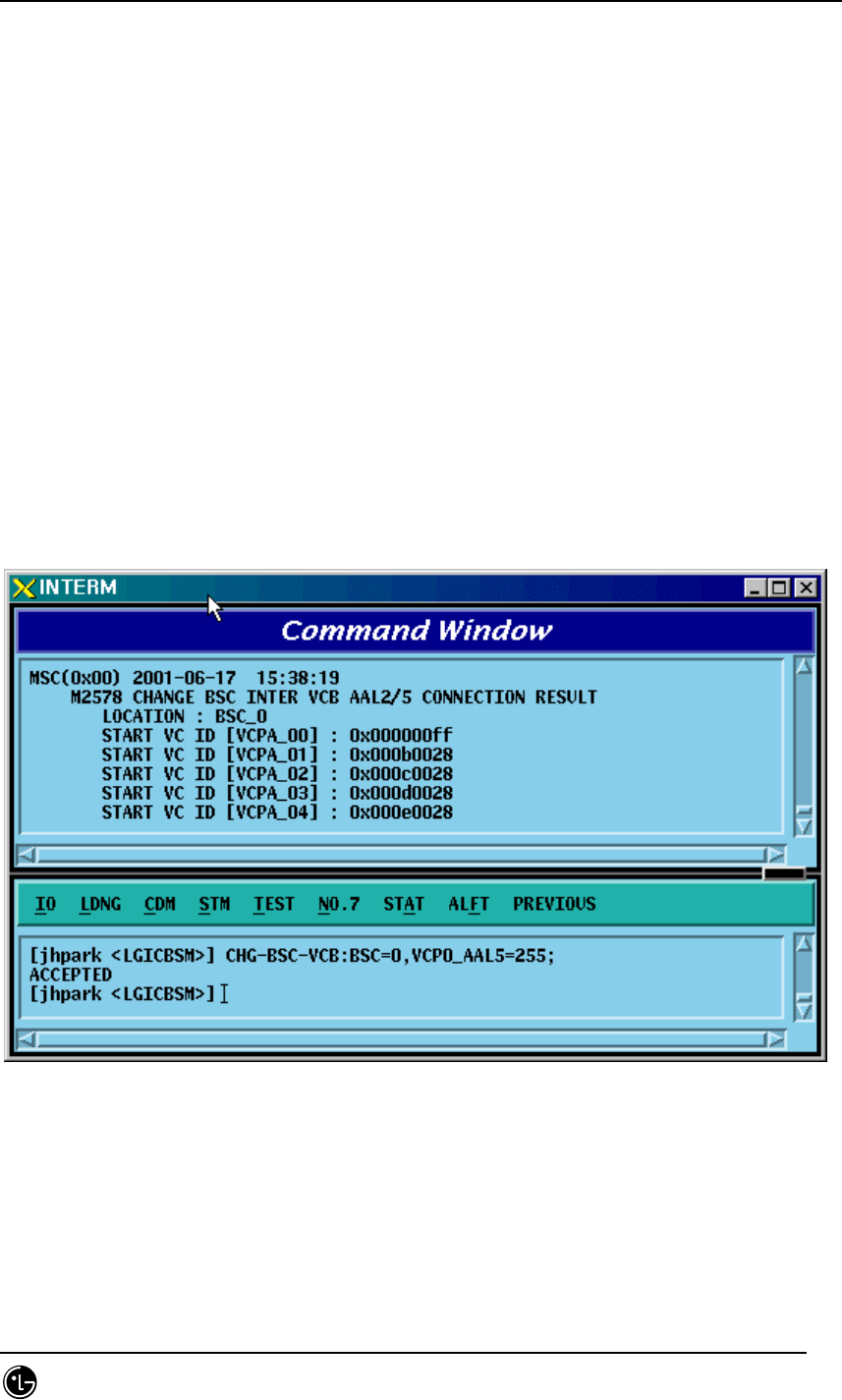
4.3.6.9. BSC INTER VCB AAL5 Setting Information Change
• Command CHG-BSC-VCB: BSC=a,
[VCP0_AAL5=b], [VCP1_AAL5=c], [VCP2_AAL5=d],
[VCP3_AAL5=e], [VCP4_AAL5=f], [VCP5_AAL5=g],
[VCP6_AAL5=h], [VCP7_AAL5=i], [VCP8_AAL5=j],
[VCP9_AAL5=k], [VCP10_AAL5=l], [VCP11_AAL5=m],
[VCP12_AAL5=n], [VCP13_AAL5=o], [VCP14_AAL5=p],
[VCP15_AAL5=q], [NO_AAL5_VC=r]
a: BSC Number(0~11)
b~q: 40~0xffffff
r: 0~88
• Input CHG-BSC-VCB: BSC=0, VCP0_AAL5=255;
• Output
STAREX-IS BSM Manual
Page:327(877)
Issue:1.
0
SMD-011-PMA210
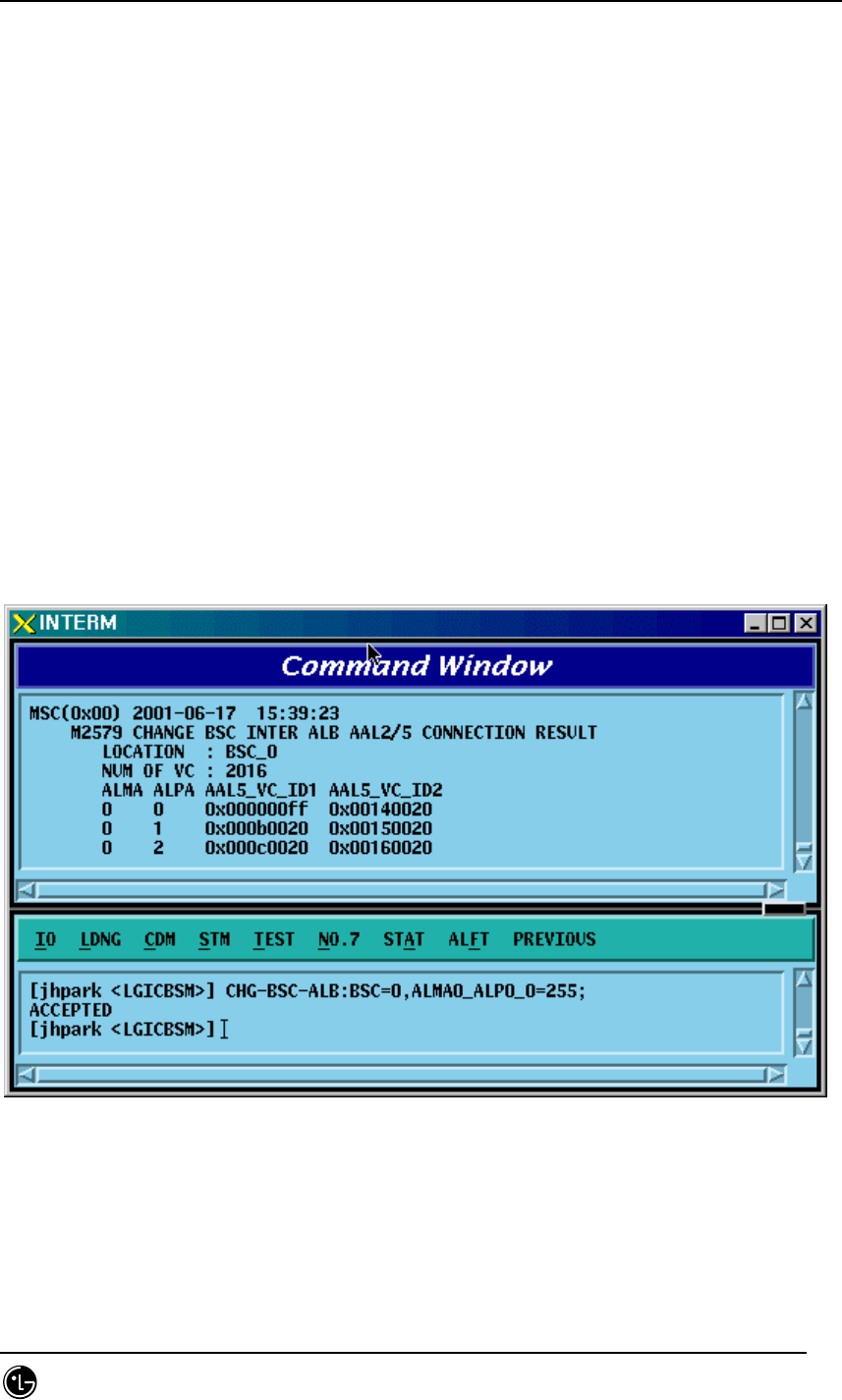
4.3.6.10. BSC INTER ALB AAL5 Setting Information Change
• Command CHG-BSC-ALB: BSC=a,
[ALMA0_ALP0_0=b], [ALMA0_ALP0_1=c], [ALMA0_ALP1_0=d],
[ALMA0_ALP1_1=e], [ALMA0_ALP2_0=f], [ALMA0_ALP2_1=g],
[ALMA0_ALP3_0=h], [ALMA0_ALP3_1=i], [ALMA0_ALP4_0=j],
[ALMA0_ALP4_1=k], [ALMA1_ALP0_0=l], [ALMA1_ALP0_1=m],
[ALMA1_ALP1_0=n], [ALMA1_ALP1_1=o], [ALMA1_ALP2_0=p],
[ALMA1_ALP2_1=q], [ALMA1_ALP3_0=r], [ALMA1_ALP3_1=s],
[ALMA1_ALP4_0=t], [ALMA1_ALP4_1=u], [NO_AAL5_VC=v]
a: BSC Number(0~11)
b~u: 32~0xffffff
v: 0~2016
• Input CHG-BSC-ALB: BSC=0, ALMA0_ALP0_0=255;
• Output
STAREX-IS BSM Manual
Page:328(877)
Issue:1.
0
SMD-011-PMA210
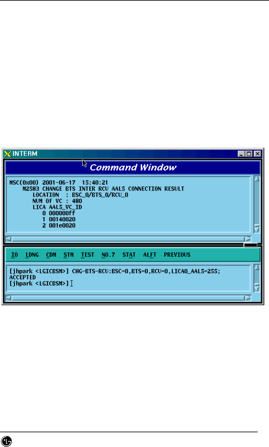
4.3.6.11. BTS INTER RCU AAL5 Setting Information Change
• Command CHG-BTS-RCU: BSC=a, BTS=b, RCU=c,
[LICA0_AAL5=d], [LICA1_AAL5=e], [LICA2_AAL5=f],
[LICA0_NO_VC=g], [LICA1_NO_VC=h], [LICA2_NO_VC=i]
a: BSC Number(0~11)
b:BTS Number(0~47)
c: RCU Number(0~9)
d~i: 0~
• Input CHG-BTS-RCU: BSC=0,BTS=0,RCU=0, LICA0_AAL5=255;
• Output

STAREX-IS BSM Manual
Page:329(877)
Issue:1.
0
SMD-011-PMA210
4.3.7. Configuration Information
Display(Display_Configuration_Data)
This section describes the comands that are used to inquire the configuration
information which is related to processors, devices, and overhead channels which are
currently used in BTS and BSC.
Table 4.3-3 Configuration Information Display
CRN MMC Description
2101 DIS-BSS-CONF BSS configuration information
verification
2103 DIS-SMP-CONF SMP configuration information
verification
2105 DIS-VMP-CONF VMP configuration information
verification
2112 DIS-BTS-CONF BTS configuration information
verification
2115 DIS-CHIP-CONF DBPA CHIP configuration information
verification
2125 DIS-OVHD-CONF OVERHEAD CHANNEL configuration
information verification
2133 DIS-PDSN-CONF PDSN configuration information
verification
STAREX-IS BSM Manual
Page:330(877)
Issue:1.
0
SMD-011-PMA210
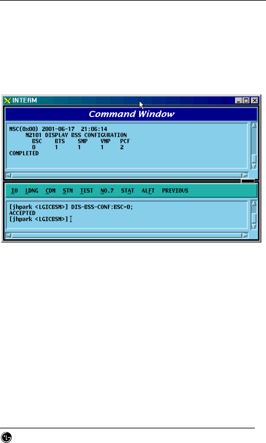
4.3.7.1. BSS Configuration Information Verification
This is a command to check the BTS, Processors and PCF counts in the BSC.
• Command DIS-BSS-CONF: BSC=a;
• Input DIS-BSS-CONF: BSC=0;
• Output
Fig. 4.3-126 BSS Configuration Information Display
STAREX-IS BSM Manual
Page:331(877)
Issue:1.
0
SMD-011-PMA210
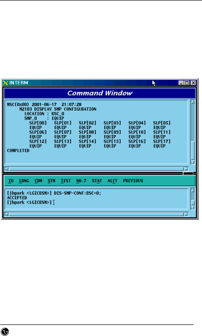
4.3.7.2. SMP Configuration Information Verification
• Command DIS-SMP-CONF: BSC=a;
a: BSC Number(#0~11)
• Input DIS-SMP-CONF: BSC=0;
• Output
Fig. 4.3-127 SMP Configuration Information Display
STAREX-IS BSM Manual
Page:332(877)
Issue:1.
0
SMD-011-PMA210
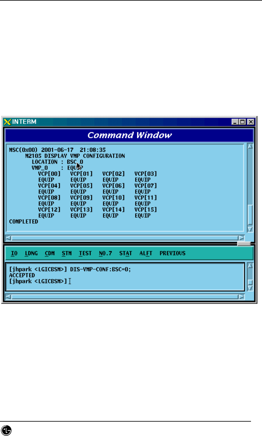
4.3.7.3. VMP Configuration Information Verification
• Command DIS-VMP-CONF: BSC=a;
a: BSC Number(#0~11)
• Input DIS-VMP-CONF: BSC=0;
• Output
Fig. 4.3-128 VMP Configuration Information Display
STAREX-IS BSM Manual
Page:333(877)
Issue:1.
0
SMD-011-PMA210
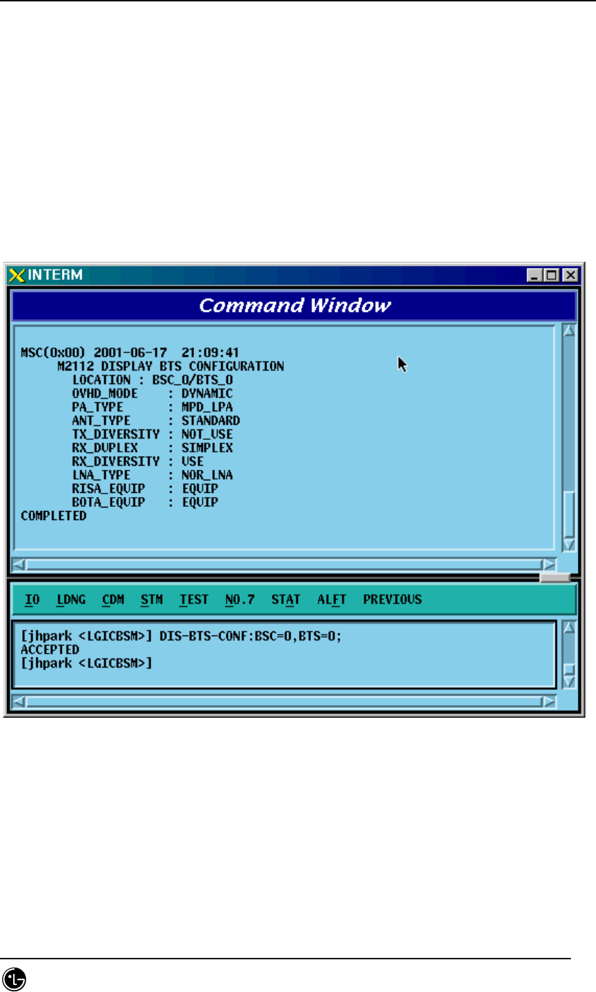
4.3.7.4. BTS Configuration Information Verification
• Command DIS-BTS-CONF: BSC=a, BTS=b;
a: BSC Number(#0~11)
b: BTS Number(#0~47)
• Input DIS-BTS-CONF: BSC=0, BTS=0;
• Output
Fig. 4.3-129 BTS Configuration Information Display
STAREX-IS BSM Manual
Page:334(877)
Issue:1.
0
SMD-011-PMA210
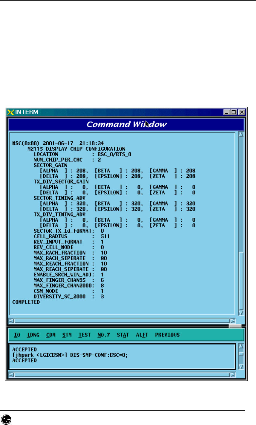
4.3.7.5. DBPA CHIP Configuration Information Verification
• Command DIS-CHIP-CONF: BSC=a, BTS=b;
a: BSC Number(#0~11)
b: BTS Number(#0~47)
• Input DIS-CHIP-CONF: BSC=0, BTS=0;
• Output
Fig. 4.3-130 DBPA CHIP Configuration Information Display
STAREX-IS BSM Manual
Page:335(877)
Issue:1.
0
SMD-011-PMA210
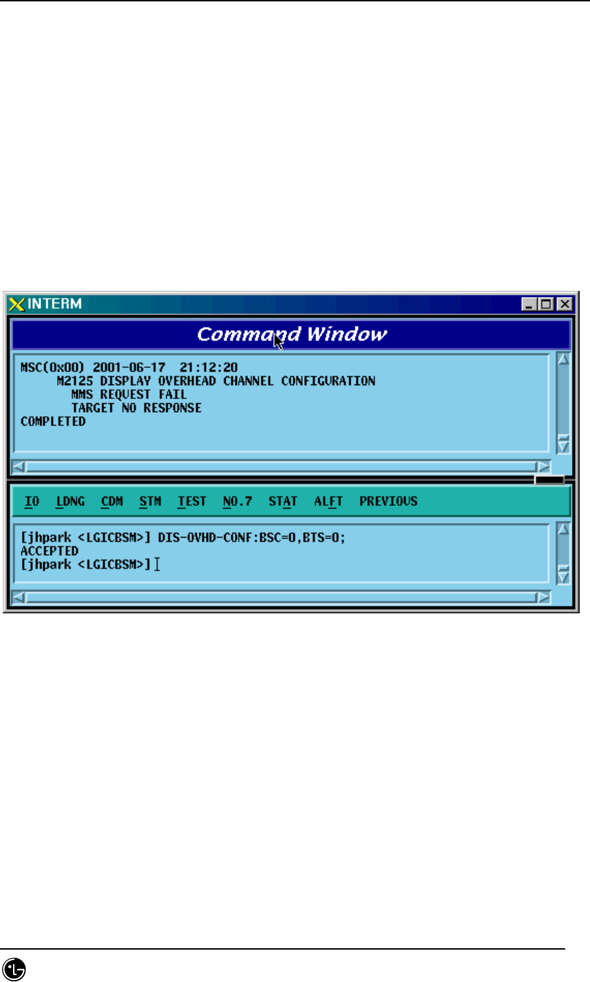
4.3.7.6. OVERHEAD CHANNEL Configuration Information Verification
• Command DIS-OVHD-CONF: BSC=a, BTS=b;
a: BSC Number(#0~11)
b: BTS Number(#0~47)
• Input DIS-OVHD-CONF: BSC=0, BTS=0;
• Output
Fig. 4.3-131 OVHD Channel Configuration Information Display
STAREX-IS BSM Manual
Page:336(877)
Issue:1.
0
SMD-011-PMA210
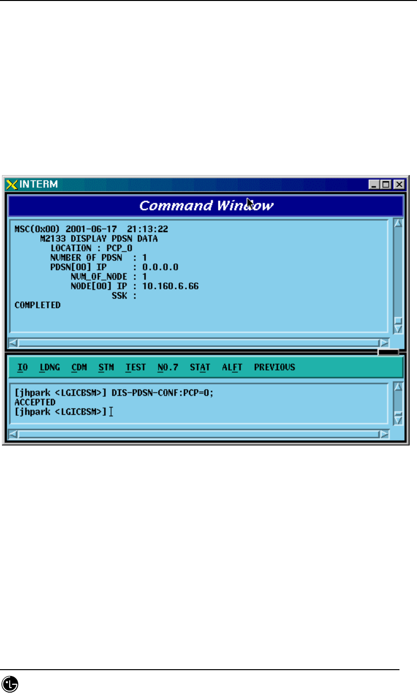
4.3.7.7. PDSN Configuration Information Verification
• Command DIS-PDSN-CONF: PCP=a;
a: PCP Number(#0~2)
• Input DIS-PDSN-CONF: PCP=0;
• Output
Fig. 4.3-132 PDSN Configuration Information Display

STAREX-IS BSM Manual
Page:337(877)
Issue:1.
0
SMD-011-PMA210
4.3.8. Configuration Information Change
(Change_Configuration_Data)
This section describes commands that are used to add or delete BTS and BSC
processors and devices. The configuration information that can be added and deleted
are presented below. For the command that has many parameters to input, input image
on the inpout Widow. This section does not cover details of each parameter.
Table 4.3-4 Configuration Information Change
CRN MMC Description
C2312 CHG-BTS-CONF BTS configuration information change
C2315
CHG-CHIP1-CONF
Channel Card Chip configuration
information(1) change
C2317
CHG-CHIP2-CONF
Channel Card Chip configuration
information(2) change
C2333 ADD-PDSN-CONF PDSN CONFIG addition
C2334 RMV-PDSN-CONF PDSN CONFIG deletion
C2335 CHG-PDSN-CONF PDSN CONFIG change
C2337 ADD-PDSN-NODE PDSN NODE addition
C2338 RMV-PDSN-NODE PDSN NODE deletion
C2339 CHG-PDSN-NODE PDSN NODE change
C2601 MOV-BSC-NODE BSC Node movement
C2602 MOV-PCF-NODE PCF Node movement
C2603 MOV-SMP-NODE SMP Node movement
C2604 MOV-VMP-NODE VMP Node movement
C2605 MOV-BTS-ID BTS ID movement
C2606 MOV-BTS-TRNK BTS TRUNK Node movement
C2607 MOV-LICA-LINK LICA LINK movement
C2610 MOV-OVHD-CONF OVERHEAD CHANNEL configuration
information movement
C2701 ADD-BSC-CONF BSC configuration addition
C2702 RMV-BSC-CONF BSC configuration deletion
C2711 ADD-PCF-CONF PCF configuration addition
C2712 RMV-PCF-CONF PCF configuration deletion

STAREX-IS BSM Manual
Page:338(877)
Issue:1.
0
SMD-011-PMA210
C2721 ADD-SMP-CONF SMP configuration addition
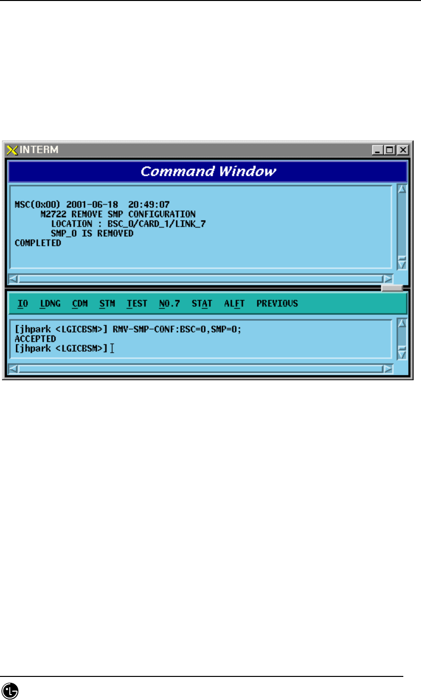
C2722 RMV-SMP-CONF SMP configuration deletion
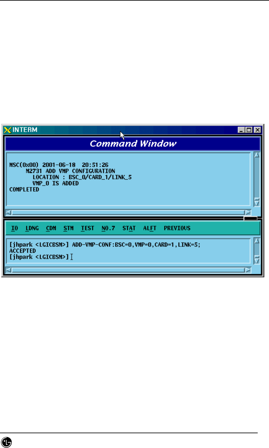
C2731 ADD-VMP-CONF VMP configuration addition
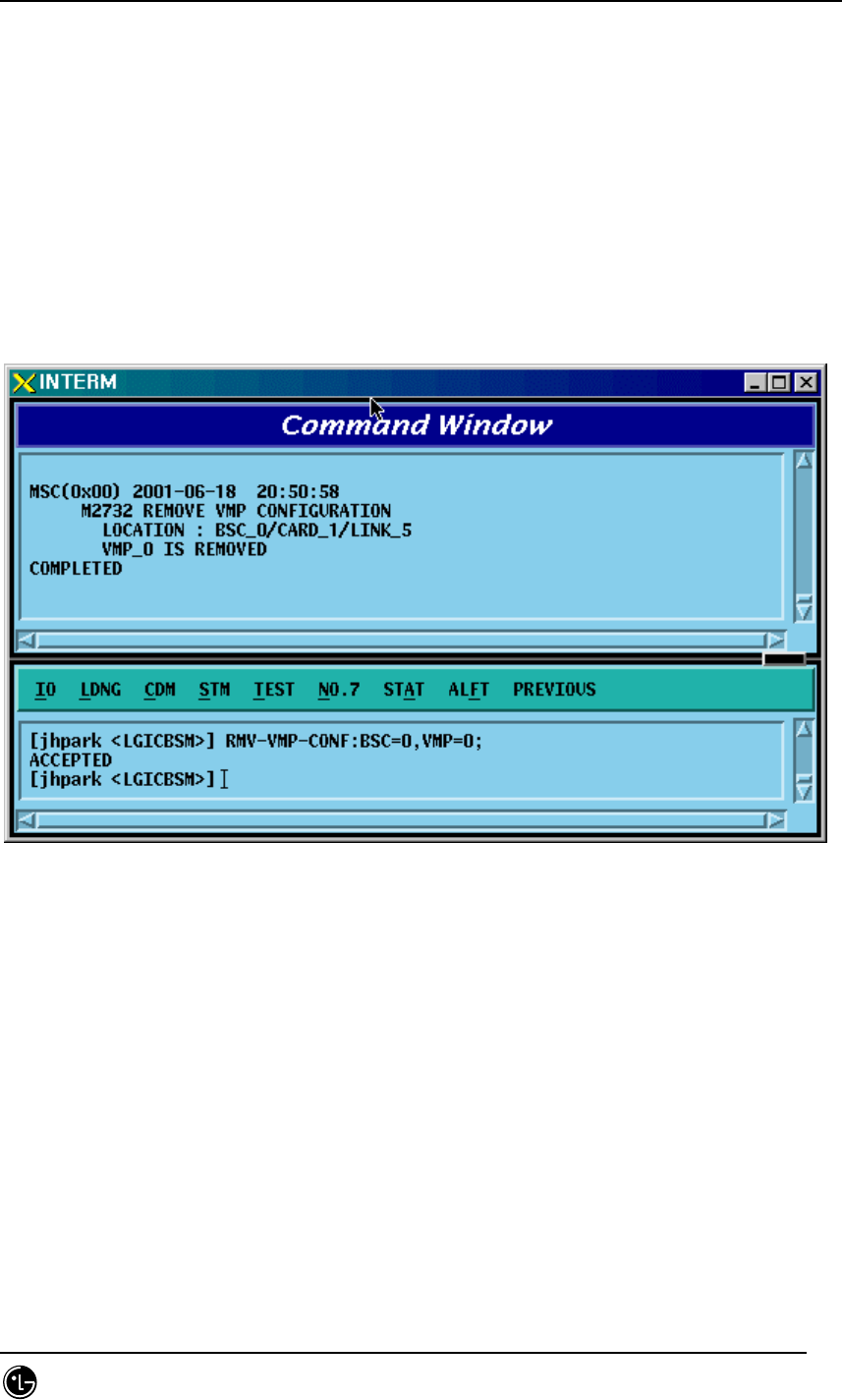
C2732 RMV-VMP-CONF VMP configuration deletion
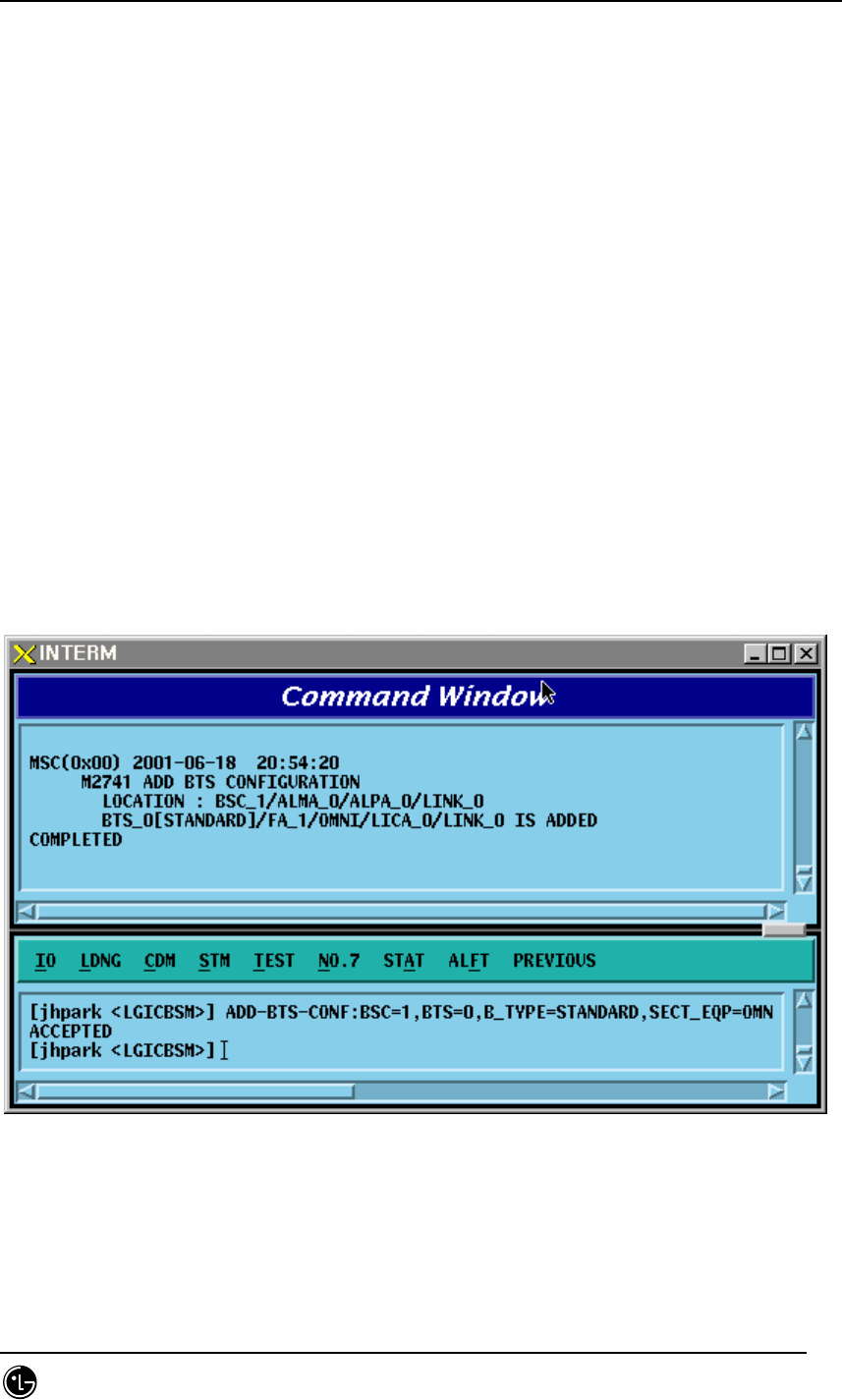
C2741 ADD-BTS-CONF BTS configuration addition
C2742 RMV-BTS-CONF BTS configuration deletion
C2751 ADD-SECT-CONF SECTOR configuration addition
C2752 RMV-SECT-CONF SECTOR configuration deletion
C2761 ADD-FA-CONF FA configuration addition
C2762 RMV-FA-CONF FA configuration deletion
C2771 ADD-TRNK-CONF BSC-BTS TRUNK configuration
addition
C2772 RMV-TRNK-CONF BSC-BTS TRUNK configuration
deletion
C2781 ADD-CAN-PVC CAN PVC configuration addition
C2782 RMV-CAN-PVC CAN PVC configuration deletion
C2783 ADD-CPN-PVC CPN PVC configuration addition
C2784 RMV-CPN-PVC CPN PVC configuration deletion
C2785 ADD-BSC-PVC BSC PVC configuration addition
C2786 RMV-BSC-PVC BSC PVC configuration deletion
STAREX-IS BSM Manual
Page:339(877)
Issue:1.
0
SMD-011-PMA210
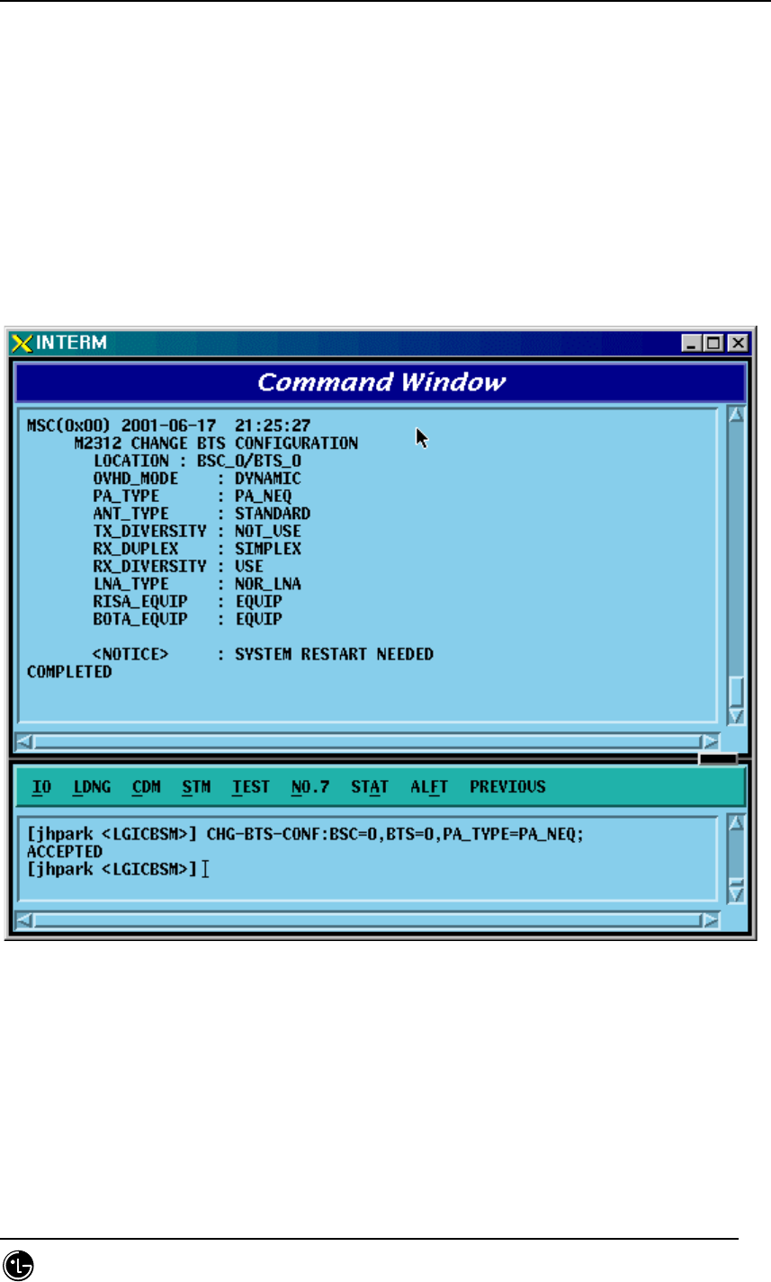
4.3.8.1. BTS Configuration Information Change
• Command CHG-BTS-CONF :BSC=a ,BTS=b [,PA_TYPE=c] [,ANT_TYPE=d]
[,ANT_DUP=e] [,RX_DIV=f] [,LNA_EQP=g] [,RISA_EQP=h] [,BOTA_EQP=i];
• Input CHG-BTS-CONF: BSC=0, BTS=0,PA_TYPE=FA_NEQ;
• Output
Fig. 4.3-133 BTS Configuration Information Change Display

STAREX-IS BSM Manual
Page:340(877)
Issue:1.
0
SMD-011-PMA210
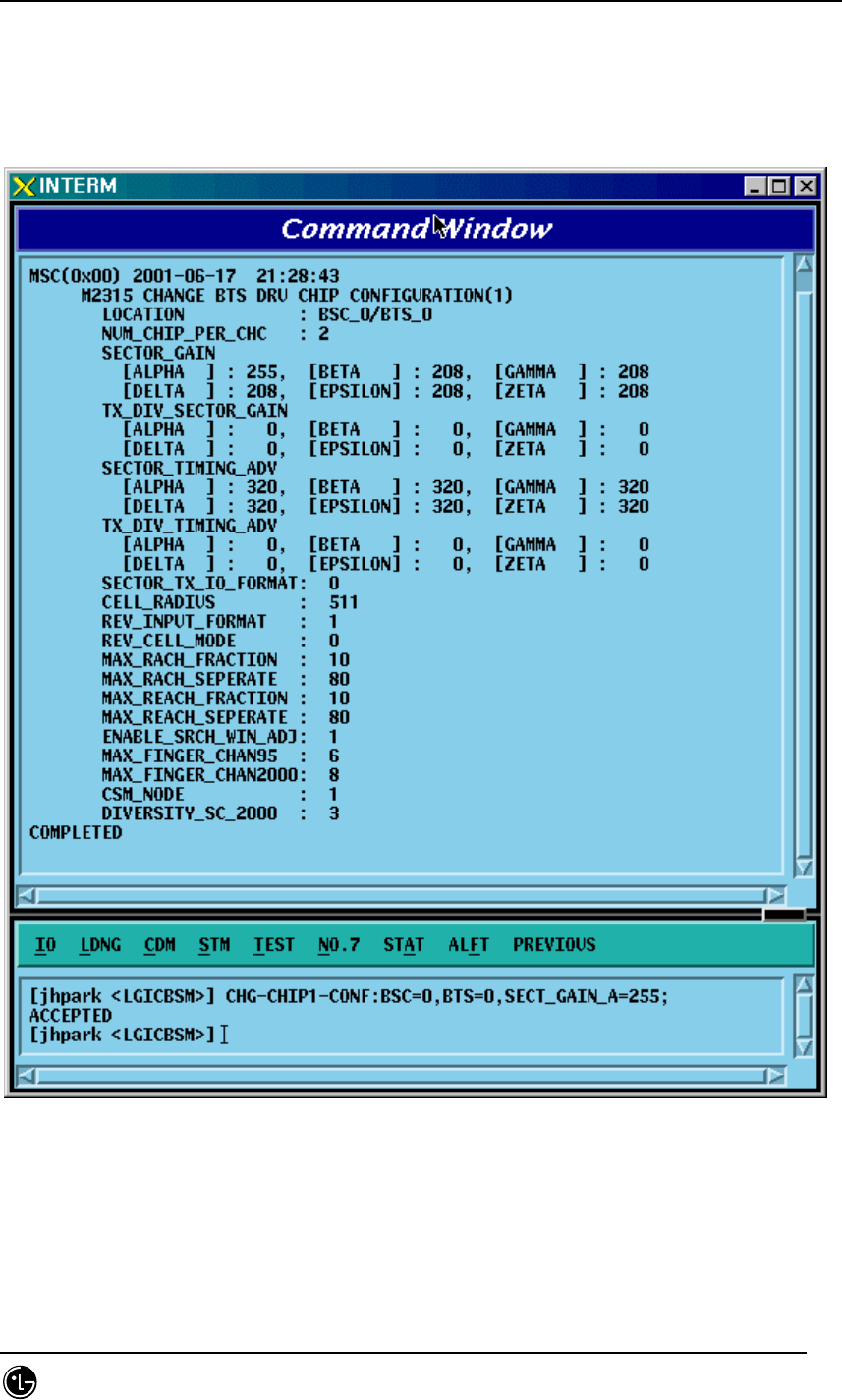
4.3.8.2. Channel Card Chip Configuration Information (1) Change
• Command CHG-CHIP1-CONF :BSC=a ,BTS=b [,SECT_GAIN_A=c]
[,SECT_GAIN_B=d]
[,SECT_GAIN_G=e] [,SECT_GAIN_D=f] [,SECT_GAIN_E=g]
[,SECT_GAIN_Z=h] [,T_DIV_SECT_A=i] [,T_DIV_SECT_B=j]
[,T_DIV_SECT_G=k] [,T_DIV_SECT_D=l] [,T_DIV_SECT_E=m]
[,T_DIV_SECT_Z=n] [,SECT_T_ADV_A=o]
[,SECT_T_ADV_B=p] [,SECT_T_ADV_G=q] [,SECT_T_ADV_D=r]
[,SECT_T_ADV_E=s] [,SECT_T_ADV_Z=t] [,T_DIV_T_ADV_A=u]
[,T_DIV_T_ADV_B=v] [,T_DIV_T_ADV_G=w] [,T_DIV_T_ADV_D=x]
[,T_DIV_T_ADV_E=y] [,T_DIV_T_ADV_Z=z];
STAREX-IS BSM Manual
Page:341(877)
Issue:1.
0
SMD-011-PMA210
• Input CHG-CHIP1-CONF:BSC=0, BTS=0,SECT_GAIN_A=255;
• Output
Fig. 4.3-134 Channel Card Chip Configuration Information (1) Change Display

STAREX-IS BSM Manual
Page:342(877)
Issue:1.
0
SMD-011-PMA210
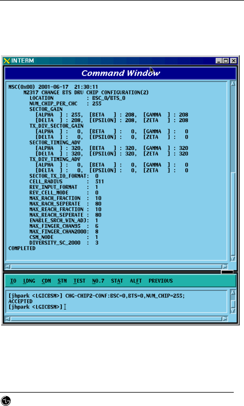
4.3.8.3. Channel Card Chip Configuration Information (2) Change
• Command CHG-CHIP2-CONF :BSC=a ,BTS=b [,NUM_CHIP=c] [,SECT_T_IO=d]
[,CELL_RADIUS=e] [,REV_IN_FORM=f] [,R_CELL_MODE=g]
[,MAX_RACH_F=h] [,MAX_RACH_S=i] [,MAX_REACH_F=j]
[,MAX_REACH_S=k] [,SRCH_WIN_ADJ=l] [,MAX_CH95=m]
[,MAX_CDMA2K=n] [,CSM_MODE=o] [,DIV_SCALE_2K=p];
STAREX-IS BSM Manual
Page:343(877)
Issue:1.
0
SMD-011-PMA210
• Input CHG-CHIP2-CONF: BSC=0, BTS=0,NUM_CHIP=255;
• Output
Fig. 4.3-135 Channel Card Chip Configuration Information (2) Change Display
STAREX-IS BSM Manual
Page:344(877)
Issue:1.
0
SMD-011-PMA210
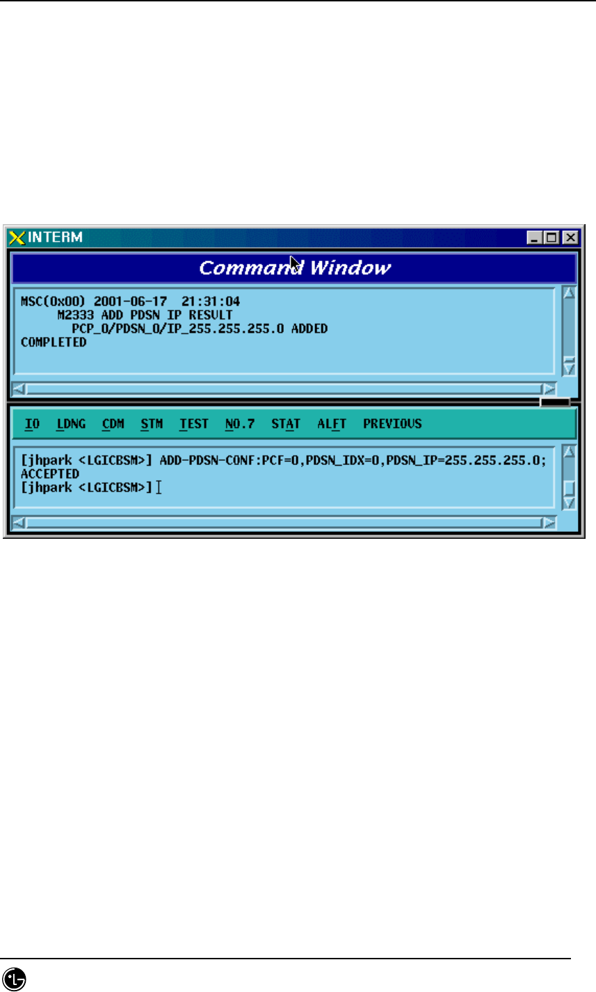
4.3.8.4. PDSN CONFIG Addition
• Command ADD-PDSN-CONF :PCF=a ,PDSN_IDX=b ,PDSN_IP=c;
• Input ADD-PDSN-CONF: BSC=0, BTS=0,PDSN_IP=255.255.255.0;
• Output
Fig. 4.3-136 PDSN Configuration Addition Display
STAREX-IS BSM Manual
Page:345(877)
Issue:1.
0
SMD-011-PMA210
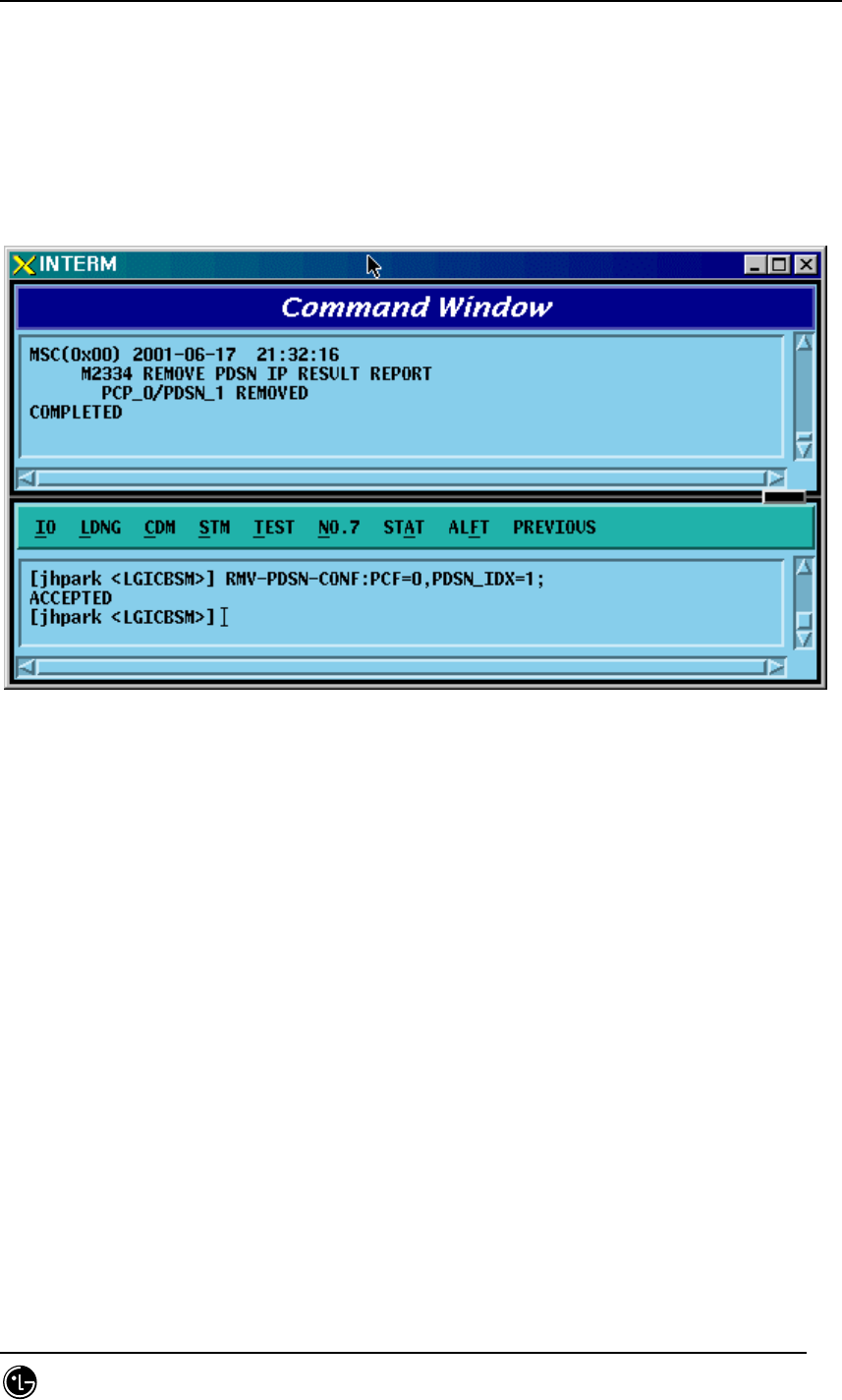
4.3.8.5. PDSN CONFIG Deletion
• Command RMV-PDSN-CONF :PCF=a ,PDSN_IDX=b;
• Input RMV-PDSN-CONF: BSC=0, BTS=0,PDSN_IDX=1;
• Output
Fig. 4.3-137 PDSN Configuration Deletion Display
STAREX-IS BSM Manual
Page:346(877)
Issue:1.
0
SMD-011-PMA210
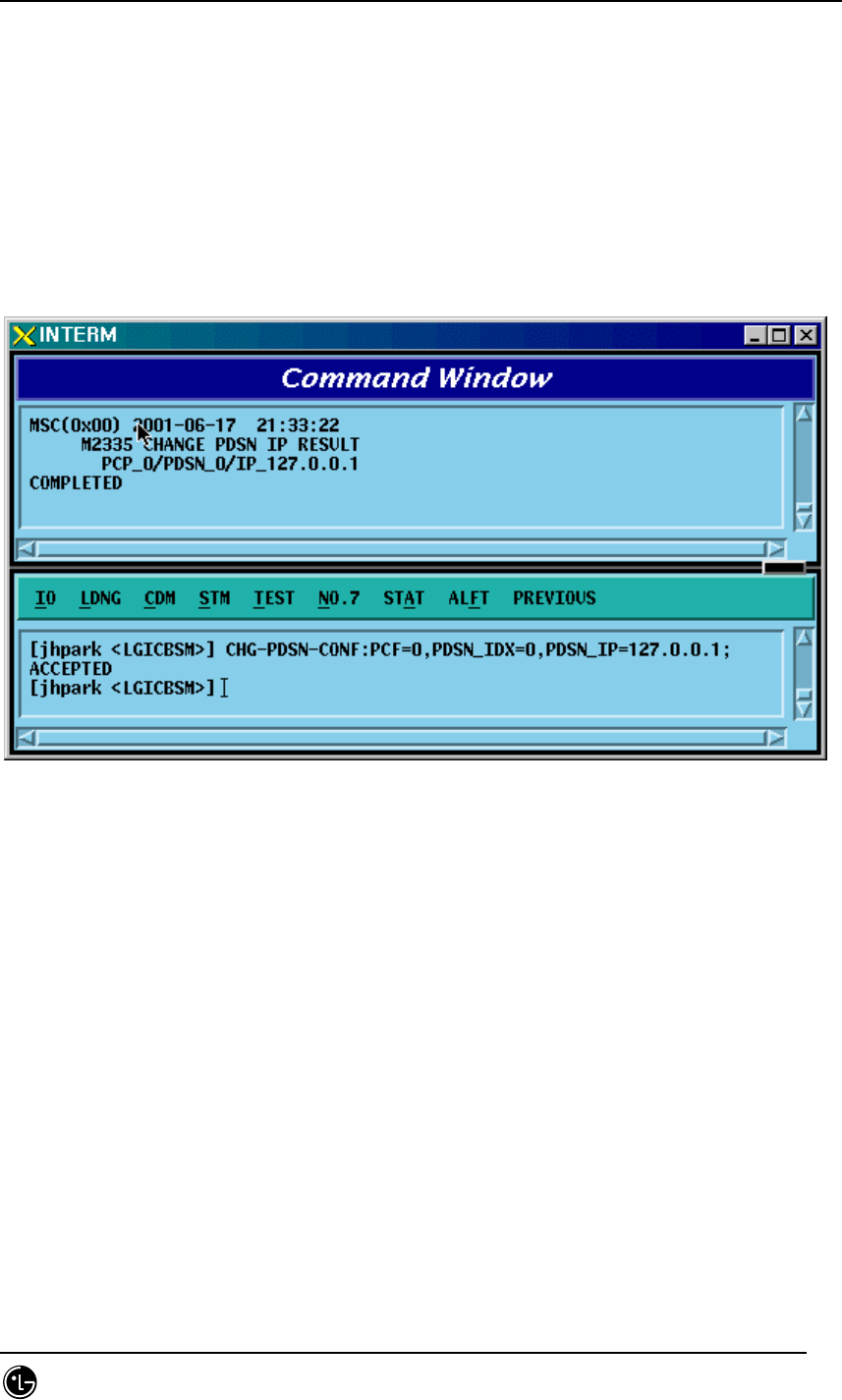
4.3.8.6. PDSN CONFIG Change
• Command CHG-PDSN-CONF :PCF=a ,PDSN_IDX=b ,PDSN_IP=c;
• Input CHG-PDSN-CONF: BSC=0, BTS=0,PDSN_IP=127.0.0.1;
• Output
Fig. 4.3-138 PDSN Configuration Change Display
STAREX-IS BSM Manual
Page:347(877)
Issue:1.
0
SMD-011-PMA210
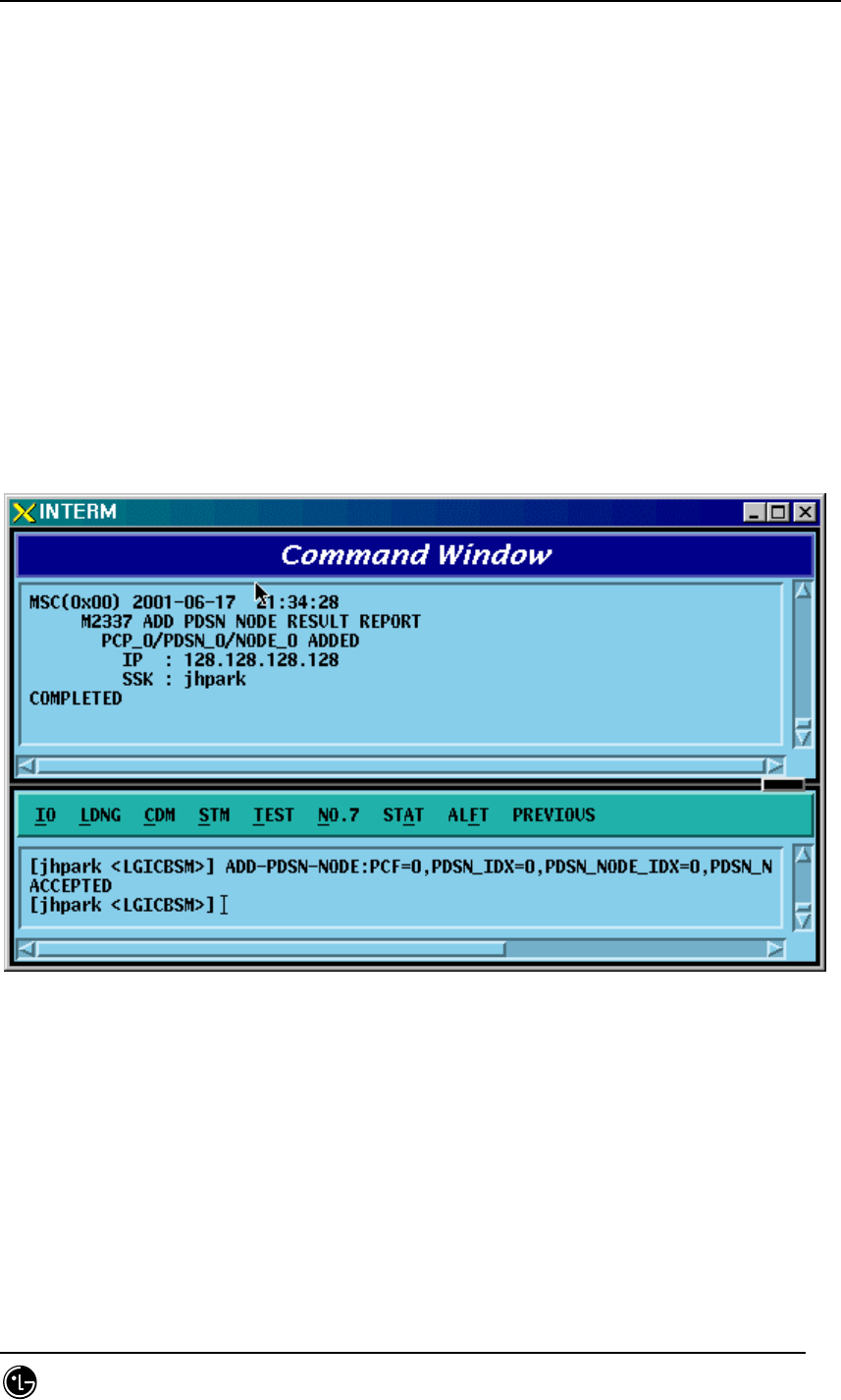
4.3.8.7. PDSN NODE Addition
• Command ADD-PDSN-NODE :PCF=a ,PDSN_IDX=b ,PDSN_NODE_IDX=c ,
PDSN_NODE_IP=d ,SSK_VALUE=e
• Input ADD-PDSN-NODE: BSC=0, BTS=0,PDSN_NODE_IDX=0,
PDSN_NODE_IP:128.128.128.128;
• Output
Fig. 4.3-139 PDSN NODE Addition Display
STAREX-IS BSM Manual
Page:348(877)
Issue:1.
0
SMD-011-PMA210
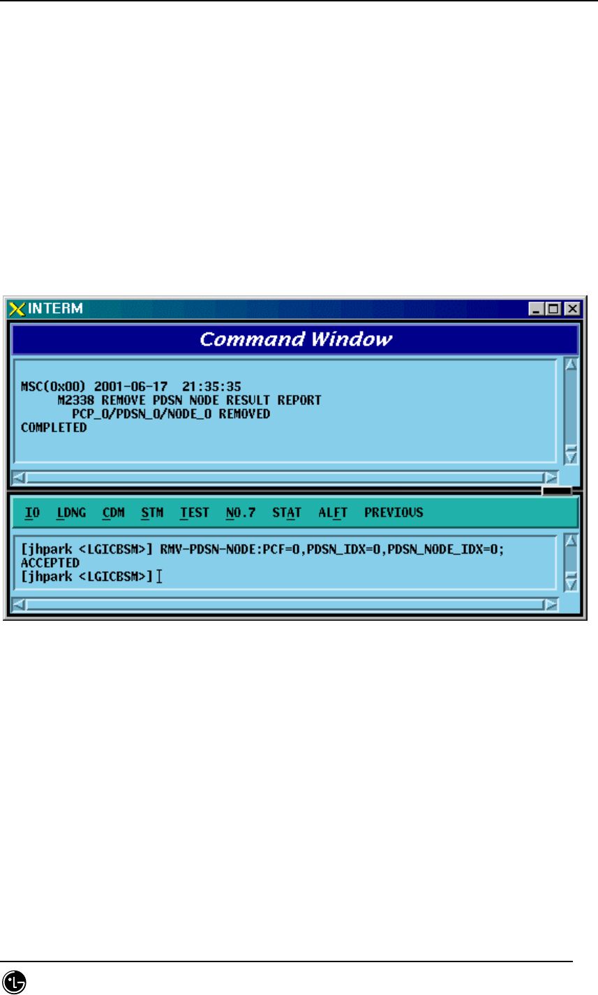
4.3.8.8. PDSN NODE Deletion
• Command RMV-PDSN-NODE :PCF=a ,PDSN_IDX=b ,PDSN_NODE_IDX=c;
• Input RMV-PDSN-NODE: BSC=0, BTS=0,PDSN_IDX=0,PDSN_NODE_IDX=0;
• Output
Fig. 4.3-140 PDSN NODE Deletion Display
STAREX-IS BSM Manual
Page:349(877)
Issue:1.
0
SMD-011-PMA210
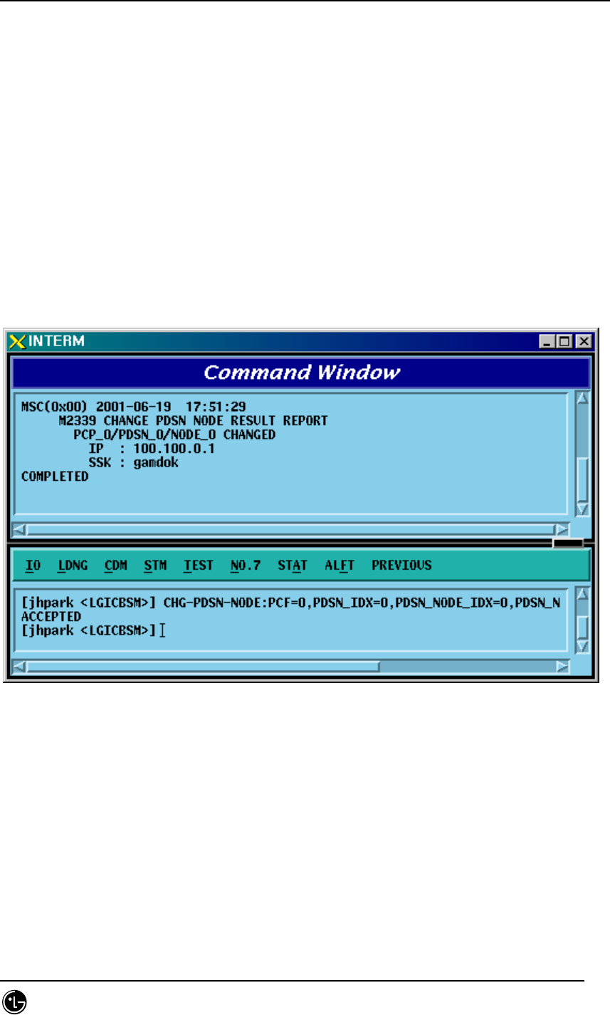
4.3.8.9. PDSN NODE Change
• Command CHG-PDSN-NODE :PCF=a ,PDSN_IDX=b ,PDSN_NODE_IDX=c
[,PDSN_NODE_IP=d] [,SSK_VALUE=e]
• Input CHG-PDSN-NODE: BSC=0, BTS=0,PDSN_IDX=0,PDSN_NODE_IDX=0,
PDSN_NODE_IP=100.100.0.1, SSK_VALUE=gamdok;
• Output
Fig. 4.3-141 PDSN NODE Change Display
STAREX-IS BSM Manual
Page:350(877)
Issue:1.
0
SMD-011-PMA210
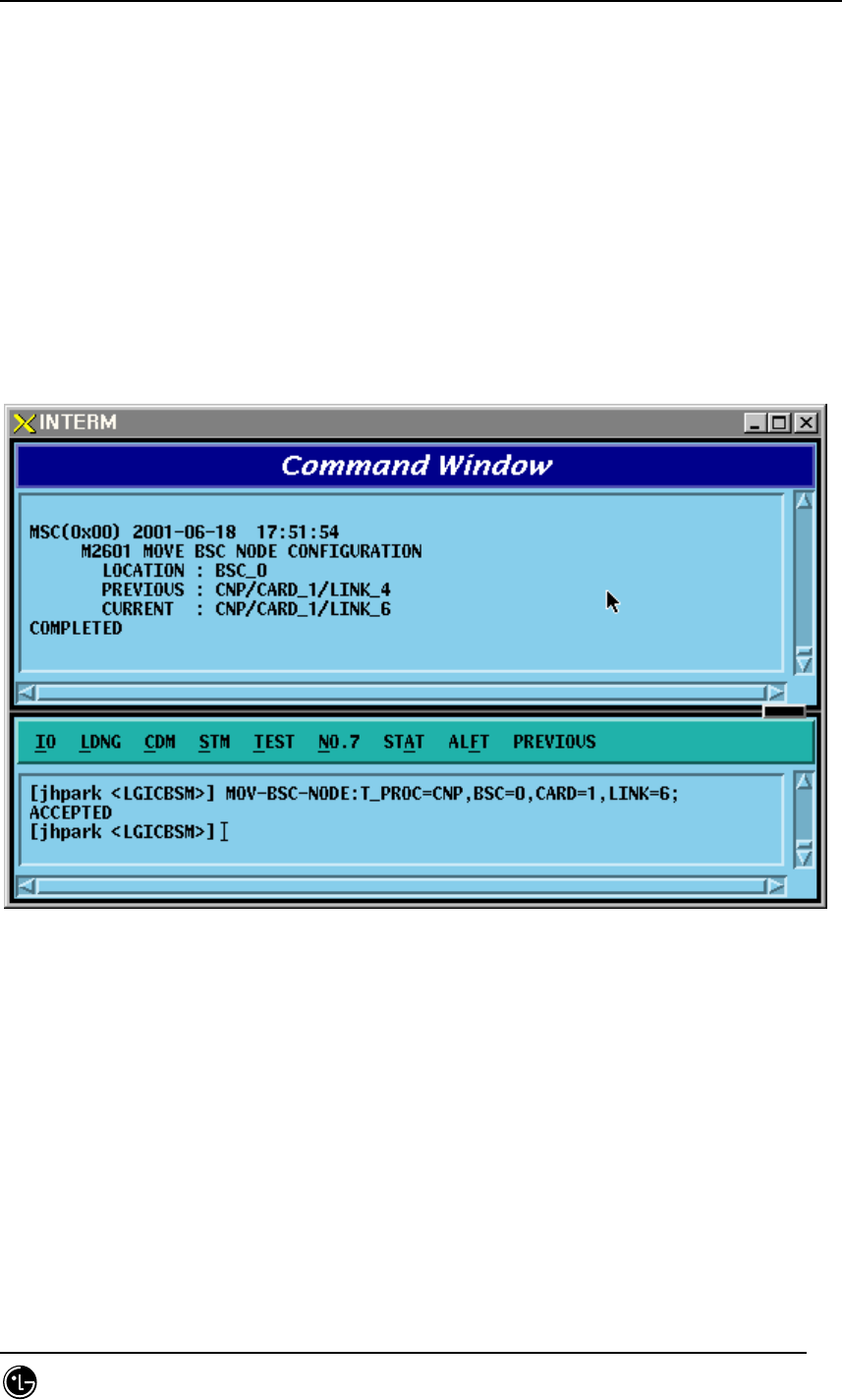
4.3.8.10. BSC Node Movement
• Command MOV-BSC-NODE :T_PROC=a ,BSC=b ,CARD=c ,LINK=d;
• Input MOV-BSC-NODE: T_PROC=CNP,BSC=0,CARD=1,LINK=6;;
• Output
Fig. 4.3-142 BSC NODE Movement Display

STAREX-IS BSM Manual
Page:351(877)
Issue:1.
0
SMD-011-PMA210
4.3.8.11. PCF Node Movement
• Command MOV-PCF-NODE :PCF=a ,CARD0=b ,LINK0=c ,CARD1=d ,LINK1=e
,CARD2=f ,LINK2=g ,CARD3=h ,LINK3=i;
• Input MOV-PCF-NODE: BSC=0, BTS=0,PA_TYPE=FA_NEQ;
• Output
STAREX-IS BSM Manual
Page:352(877)
Issue:1.
0
SMD-011-PMA210
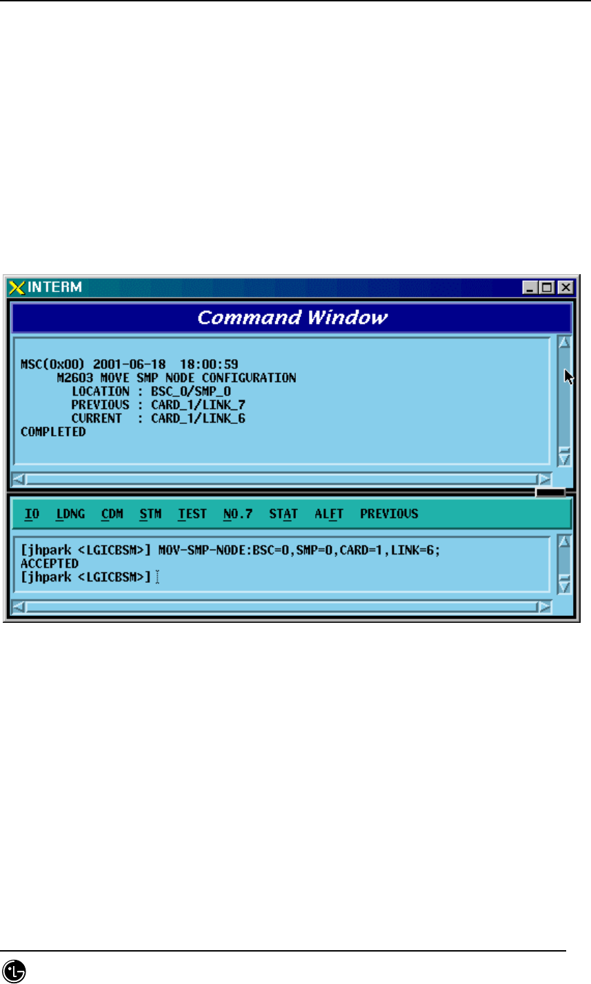
4.3.8.12. SMP Node Movement
• Command MOV-SMP-NODE :BSC=a ,SMP=b ,CARD=c ,LINK=d;
• Input MOV-SMP-NODE: BSC=0, SMP=0,CARD=1,LINK=6
• Output
Fig. 4.3-143 SMP NODE Movement Display
STAREX-IS BSM Manual
Page:353(877)
Issue:1.
0
SMD-011-PMA210
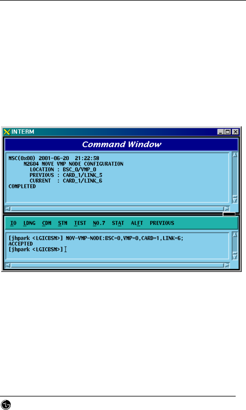
4.3.8.13. VMP Node Movement
• Command MOV-VMP-NODE :BSC=a ,VMP=b ,CARD=c ,LINK=d;
• Input MOV-VMP-NODE: BSC=0, VMP=0, CARD=1, LINK=6;
• Output
Fig. 4.3-144 VMP NODE Movement Display
STAREX-IS BSM Manual
Page:354(877)
Issue:1.
0
SMD-011-PMA210
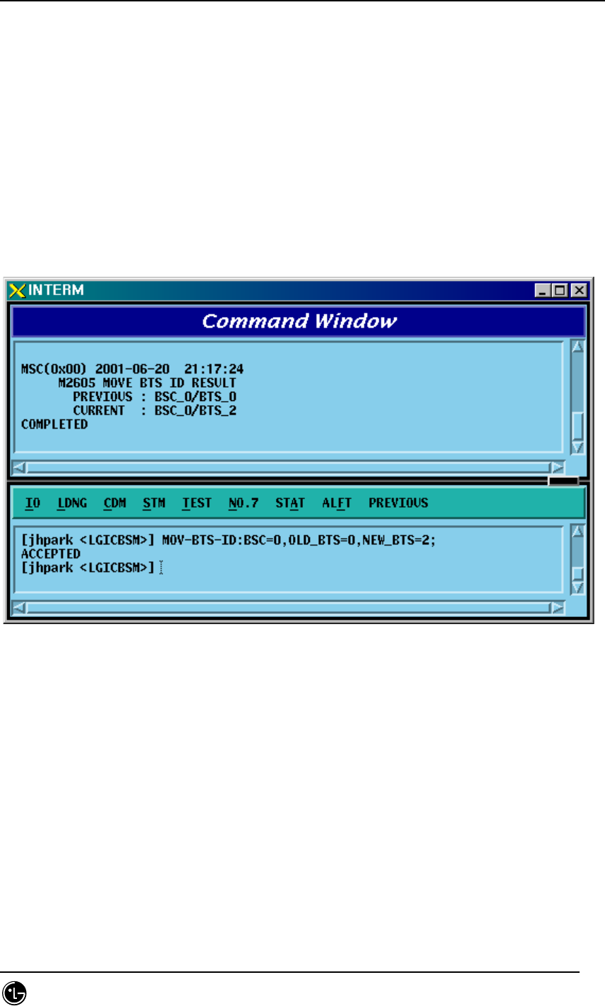
4.3.8.14. BTS ID Movement
• Command MOV-BTS-ID :BSC=a ,OLD_BTS=b ,NEW_BTS=c;
• Input MOV-BTS-ID: BSC=0, OLD_BTS=0,NEW_BTS=2;
• Output
Fig. 4.3-145 BTS ID Movement Display
STAREX-IS BSM Manual
Page:355(877)
Issue:1.
0
SMD-011-PMA210
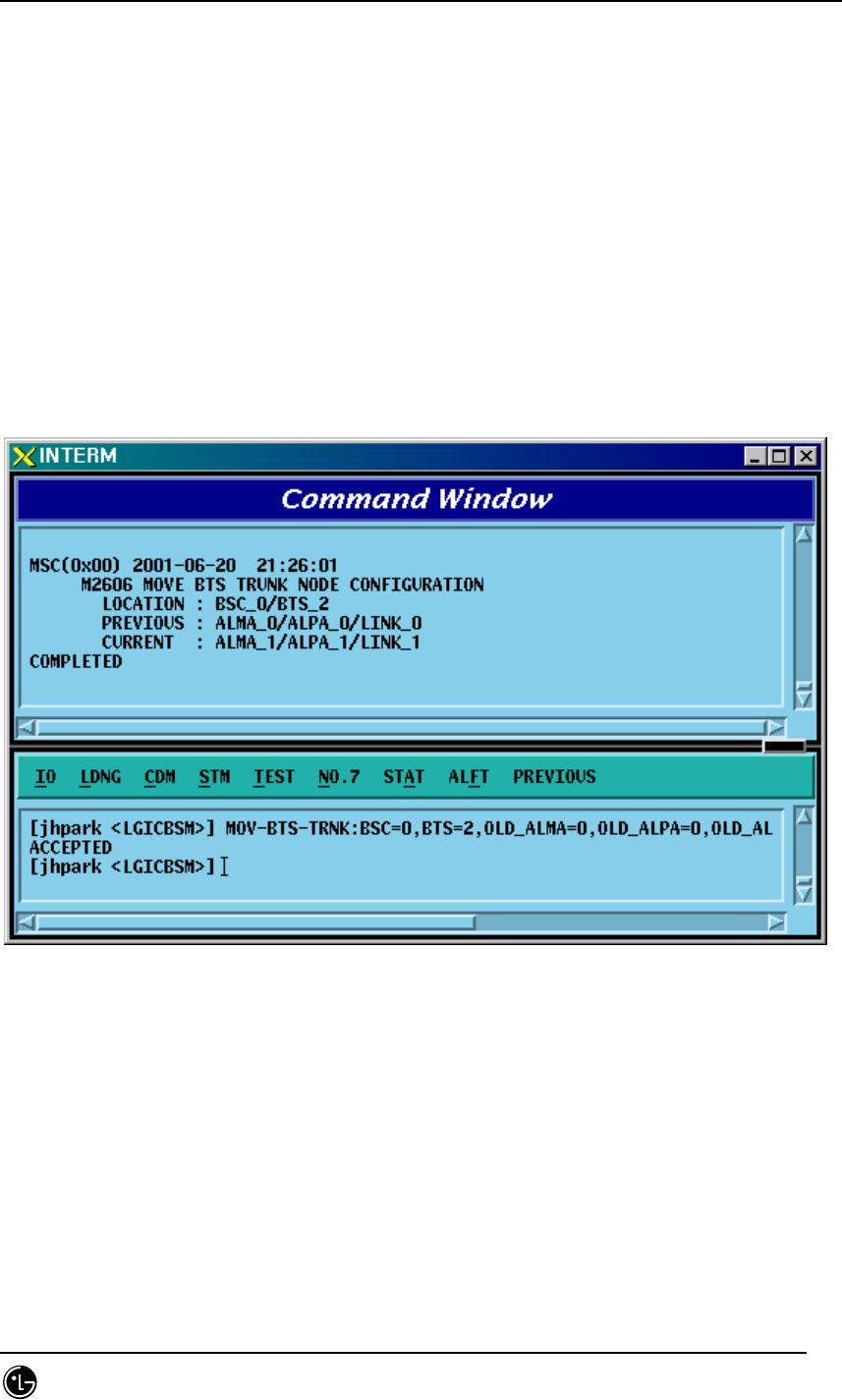
4.3.8.15. BTS TRUNK Node Movement
For this command, execute DIS-TRNK-DATA first to input the parameter value.
• Command MOV-BTS-TRNK :BSC=a ,BTS=b ,OLD_ALMA=c ,OLD_ALPA=d ,
OLD_ALPA_LINK=e ,NEW_ALMA=f ,NEW_ALPA=g ,NEW_ALPA_LINK=h;
• Input MOV-BTS-TRNK: BSC=0, BTS=2,
OLD_ALMA=0,OLD_ALPA=0,OLD_ALPA_LINK=0,
NEW_ALMA=1,NEW_ALPA=1,NEW_ALPA_LINK=1;
• Output
Fig. 4.3-146 BTS TRUNK Movement display
STAREX-IS BSM Manual
Page:356(877)
Issue:1.
0
SMD-011-PMA210
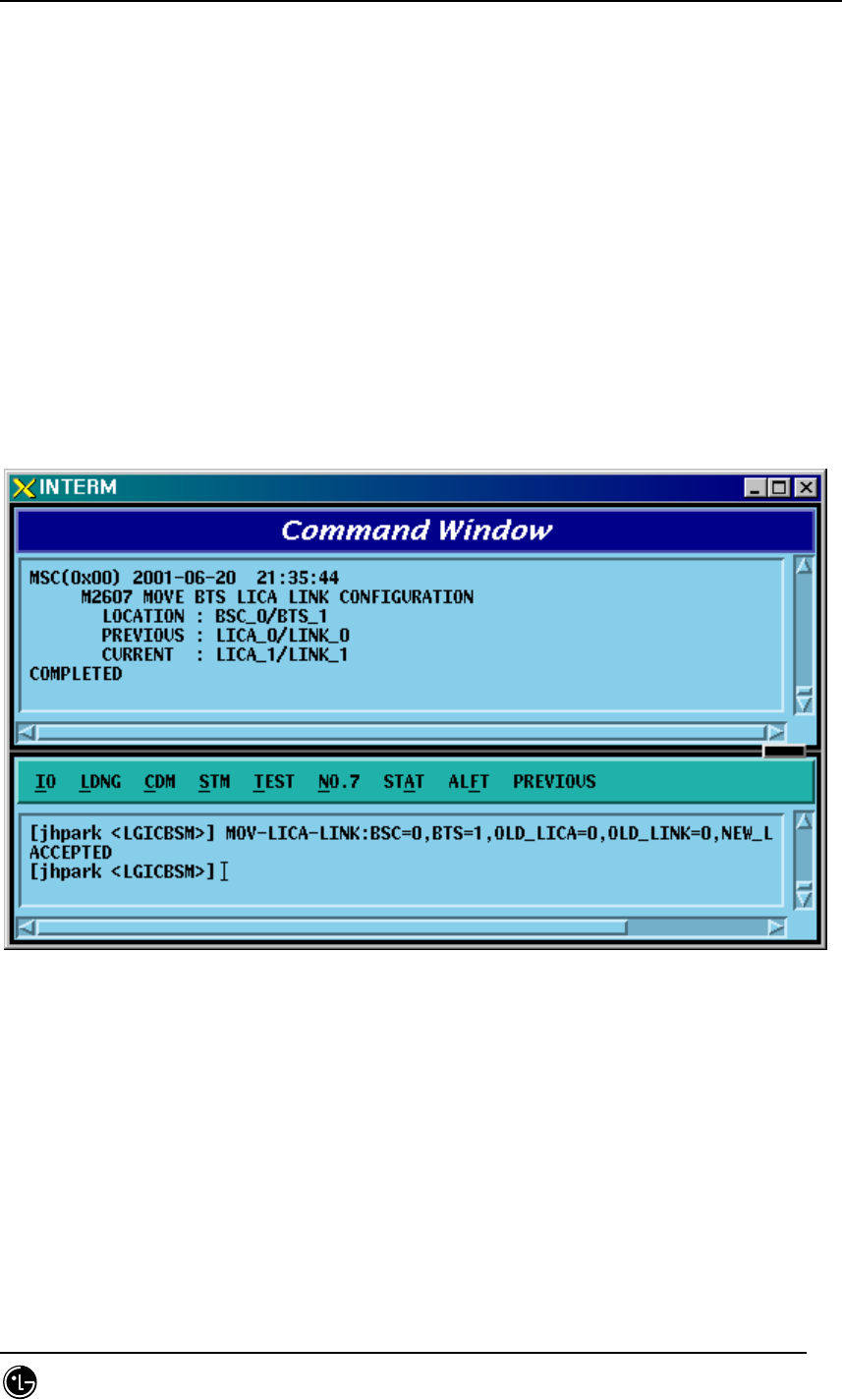
4.3.8.16. LICA LINK Movement
• Command MOV-LICA-
LINK :BSC=a ,BTS=b ,OLD_LICA=c ,OLD_LINK=d ,NEW_LICA=e
,NEW_LINK=f;
• Input MOV-LICA-LINK: BSC=0, BTS=1,
OLD_LICA=0, OLD_LINK=0,
NEW_LICA=1, NEW_LINK=1;
• Output
Fig. 4.3-147 LICA LINK Movement Display
STAREX-IS BSM Manual
Page:357(877)
Issue:1.
0
SMD-011-PMA210
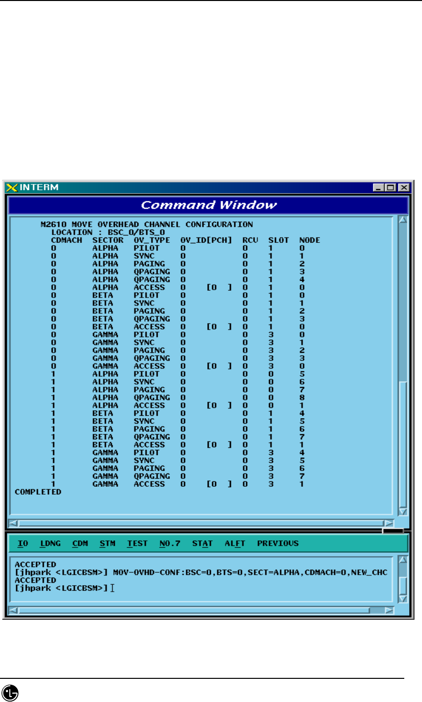
4.3.8.17. OVERHEAD CHANNEL Configuration Information Movement
Refer to DIS-OVHD-CONF command
• Command MOV-OVHD-CONF :BSC=a ,BTS=b ,SECT=c ,CDMACH=d ,
NEW_CHC=e ;
• Input MOV-OVHD-CONF: BSC=0, BTS=0,
SECTOR=ALPHA,CDMACH=0,NEW_CHC=1;
• Output
Fig. 4.3-148 OVHD Channel Configuration Information Movement Display

STAREX-IS BSM Manual
Page:358(877)
Issue:1.
0
SMD-011-PMA210
4.3.8.18. BSC Configuration Addition
• Command ADD-BSC-CONF :T_PROC=a ,BSC=b ,CARD=c ,LINK=d;
• Input ADD-BSC-CONF: BSC=0, BTS=0,PA_TYPE=FA_NEQ;
• Output

STAREX-IS BSM Manual
Page:359(877)
Issue:1.
0
SMD-011-PMA210
4.3.8.19. BSC Configuration Deletion
• Command RMV-BSC-CONF :T_PROC=a ,BSC=b;
• Input RMV-BSC-CONF: BSC=0, BTS=0,PA_TYPE=FA_NEQ;
• Output

STAREX-IS BSM Manual
Page:360(877)
Issue:1.
0
SMD-011-PMA210
4.3.8.20. PCF Configuration Addition
• Command ADD-PCF-CONF :PCF=a ,CARD0=b ,LINK0=c ,CARD1=d ,LINK1=e
,CARD2=f ,LINK2=g ,CARD3=h ,LINK3=i;
• Input ADD-PCF-
CONF:PCF=1,CARD0=3,LINK0=4,CARD1=3,LINK1=4,CARD2=3,LINK2=4,CARD3=3,LI
NK3=4;
• Output
Fig. 4.3-149 PCF Configuration Addition Display
STAREX-IS BSM Manual
Page:361(877)
Issue:1.
0
SMD-011-PMA210
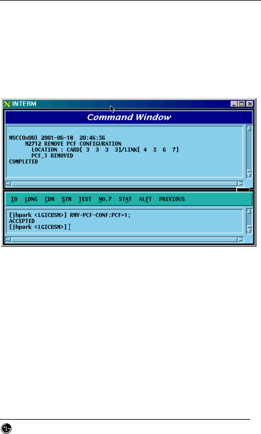
4.3.8.21. PCF Configuration Deletion
• Command RMV-PCF-CONF :PCF=a;
• Input RMV-PCF-CONF: PCF=1;
• Output
Fig. 4.3-150 PCF Configuration Deletion Display
STAREX-IS BSM Manual
Page:362(877)
Issue:1.
0
SMD-011-PMA210
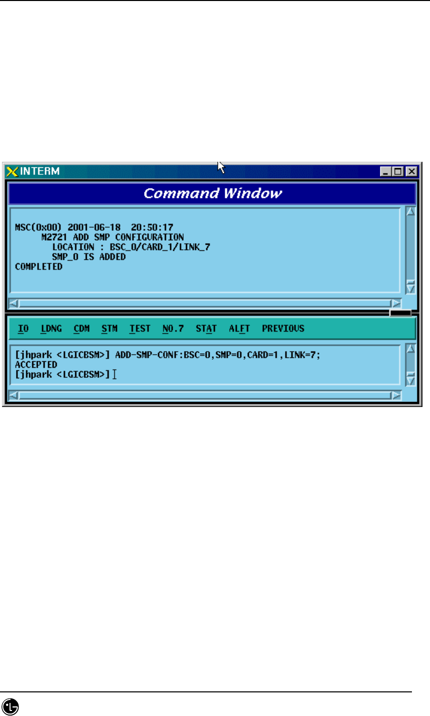
4.3.8.22. SMP Configuration Addition
• Command ADD-SMP-CONF :BSC=a ,SMP=b ,CARD=c ,LINK=d;
• Input ADD-SMP-CONF: BSC=0,SMP=0,CARD=1,LINK=7;
• Output
Fig. 4.3-151 SMP Configuration Addition Display
STAREX-IS BSM Manual
Page:363(877)
Issue:1.
0
SMD-011-PMA210
4.3.8.23. SMP Configuration Deletion
• Command RMV-SMP-CONF :BSC=a ,SMP=b;
• Input RMV-SMP-CONF: BSC=0, SMP=0;
• Output
Fig. 4.3-152 SMP Configuration Deletion Display
STAREX-IS BSM Manual
Page:364(877)
Issue:1.
0
SMD-011-PMA210
4.3.8.24. VMP Configuration Addition
• Command ADD-VMP-CONF :BSC=a ,VMP=b ,CARD=c ,LINK=d;
• Input ADD-VMP-CONF: BSC=0,VMP=0,CARD=1,LINK=5;
• Output
Fig. 4.3-153 VMP Configuration Addition Display
STAREX-IS BSM Manual
Page:365(877)
Issue:1.
0
SMD-011-PMA210
4.3.8.25. VMP Configuration Deletion
• Command RMV-VMP-CONF :BSC=a ,VMP=b;
• Input RMV-VMP-CONF: BSC=0, VMP=0;
• Output
Fig. 4.3-154 VMP Configuration Deletion Display
STAREX-IS BSM Manual
Page:366(877)
Issue:1.
0
SMD-011-PMA210
4.3.8.26. BTS Configuration Addition
• Command ADD-BTS-
CONF :BSC=a ,BTS=b ,B_TYPE=c ,SECT_EQP=d ,SECT_RANGE=e
,ALMA=f ,ALPA=g ,ALPA_LINK=h ,LICA=i ,LICA_LINK=j
,FA0_CH_NUM=k ,PN_ALPHA=l [,PN_BETA=m]
[,PN_GAMMA=n] [,PN_DELTA=o] [,PN_EPSILON=p]
[,PN_ZETA=q] [,PA_TYPE=r] [,ANT_TYPE=s] [,LNA_TYPE=t]
[,RISA_EQP=u] [,BOTA_EQP=v];
• Input Input ADD-BTS-CONF: BSC=0, BTS=0; -> ADD-BTS-CONF: BSC=1,
BTS=0,B_TYPE=STANDARD,SECT_EQP=OMNI;
• Output
STAREX-IS BSM Manual
Page:367(877)
Issue:1.
0
SMD-011-PMA210
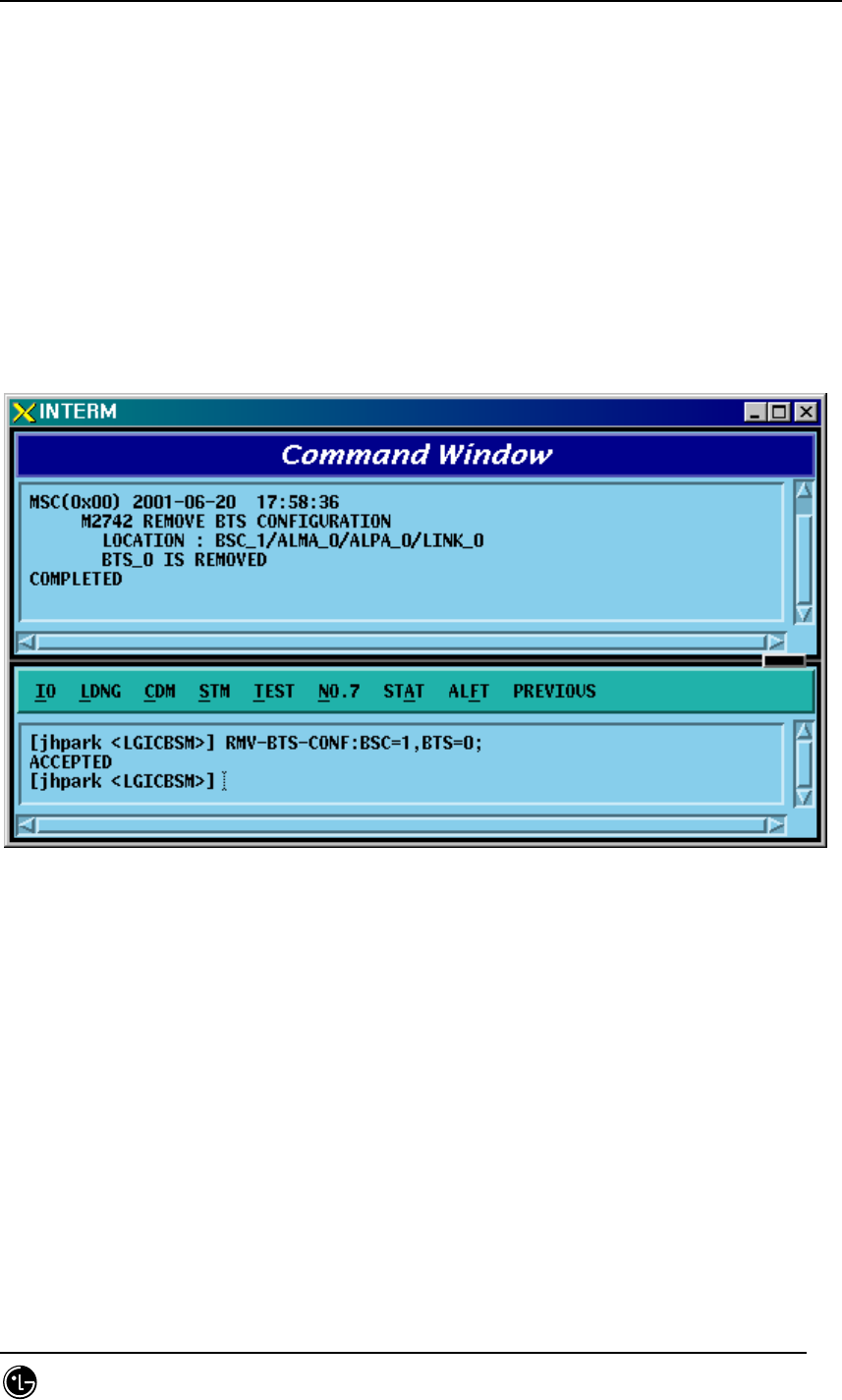
4.3.8.27. BTS Configuration Deletion
• Command RMV-BTS-CONF :BSC=a ,BTS=b;
• Input RMV-BTS-CONF: BSC=1, BTS=0;
• Output
Fig. 4.3-155 BTS Configuration Deletion Display

STAREX-IS BSM Manual
Page:368(877)
Issue:1.
0
SMD-011-PMA210
4.3.8.28. SECTOR Configuration Addition
• Command ADD-SECT-CONF :BSC=a ,BTS=b ,SECT=c ,PN=d;
• Input ADD-SECT-CONF: BSC=0, BTS=0,PA_TYPE=FA_NEQ;
• Output

STAREX-IS BSM Manual
Page:369(877)
Issue:1.
0
SMD-011-PMA210
4.3.8.29. SECTOR Configuration Deletion
• Command RMV-SECT-CONF :BSC=a ,BTS=b ,SECT=c;
• Input RMV-SECT-CONF: BSC=0, BTS=0,PA_TYPE=FA_NEQ;
• Output
STAREX-IS BSM Manual
Page:370(877)
Issue:1.
0
SMD-011-PMA210
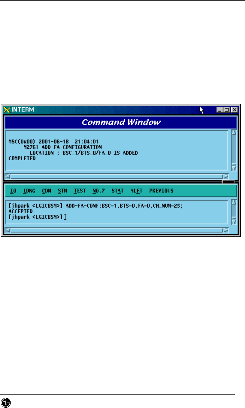
4.3.8.30. FA Configuration Addition
• Command ADD-FA-CONF :BSC=a ,BTS=b ,FA=c ,CH_NUM=d;
• Input ADD-FA-CONF: BSC=1, BTS=0,FA=0,CH_NUM=25;
• Output
Fig. 4.3-156 FA Configuration Addition Display
STAREX-IS BSM Manual
Page:371(877)
Issue:1.
0
SMD-011-PMA210
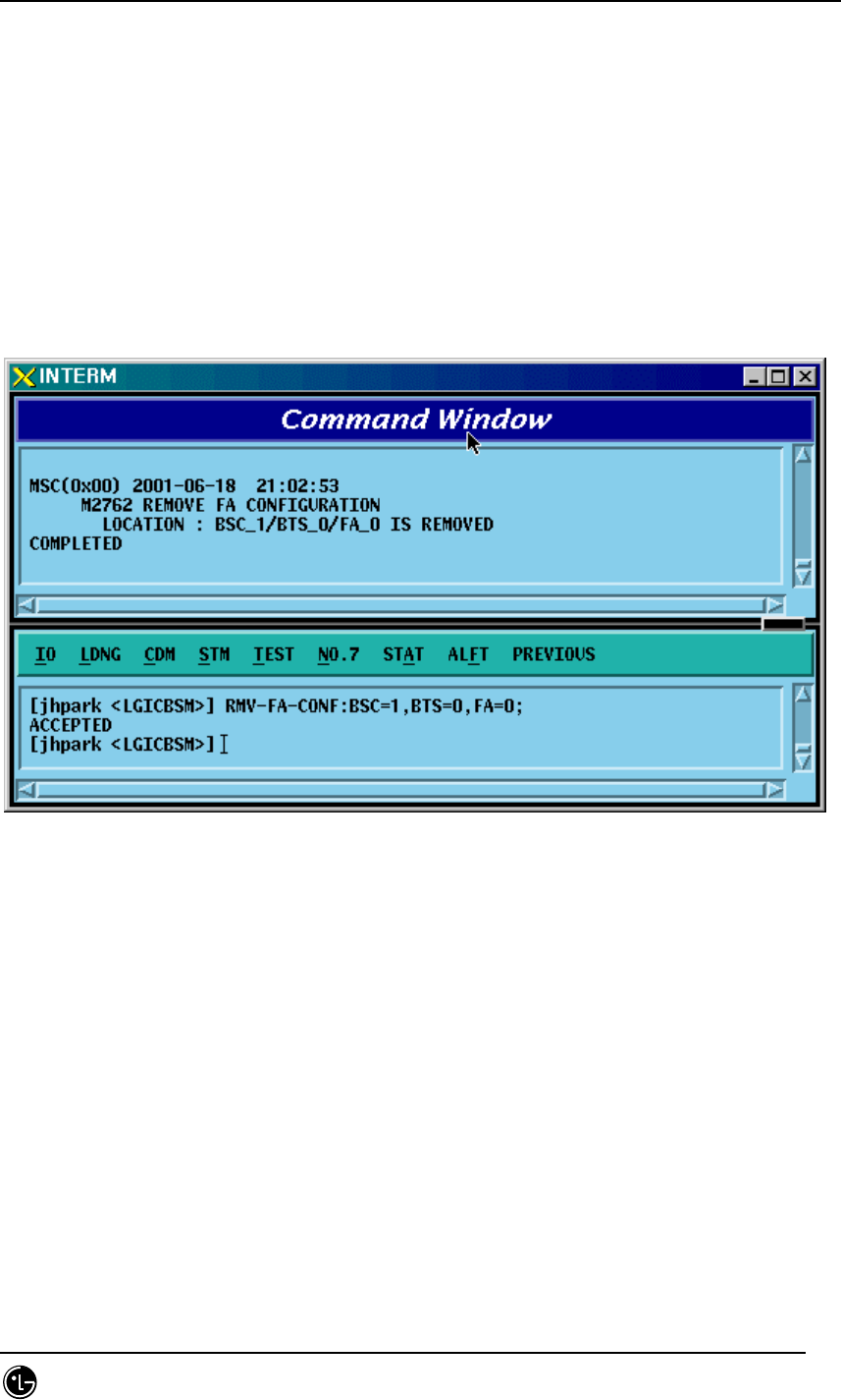
4.3.8.31. FA Configuration Deletion
• Command RMV-FA-CONF :BSC=a ,BTS=b ,FA=c;
• Input RMV-FA-CONF: BSC=1, BTS=0,FA=0;
• Output
Fig. 4.3-157 FA Configuration Deletion Display

STAREX-IS BSM Manual
Page:372(877)
Issue:1.
0
SMD-011-PMA210
4.3.8.32. BSC-BTS TRUNK Configuration Addition
• Command ADD-TRNK-CONF :BSC=a ,BTS=b ,ALMA=c ,ALPA=d ,ALPA_LINK=e
,LICA=f ,LICA_LINK=g ,ALLOC_TYPE=h;
• Input ADD-TRNK-CONF: BSC=0, BTS=0,PA_TYPE=FA_NEQ;
• Output

STAREX-IS BSM Manual
Page:373(877)
Issue:1.
0
SMD-011-PMA210
4.3.8.33. BSC-BTS TRUNK Configuration Deletion
• Command RMV-TRNK-CONF :BSC=a ,BTS=b ,ALMA=c ,ALPA=d ,ALPA_LINK=e ;
• Input RMV-TRNK-CONF: BSC=0, BTS=0,PA_TYPE=FA_NEQ;
• Output
STAREX-IS BSM Manual
Page:374(877)
Issue:1.
0
SMD-011-PMA210
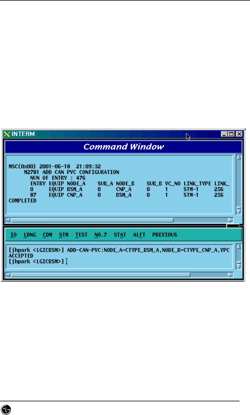
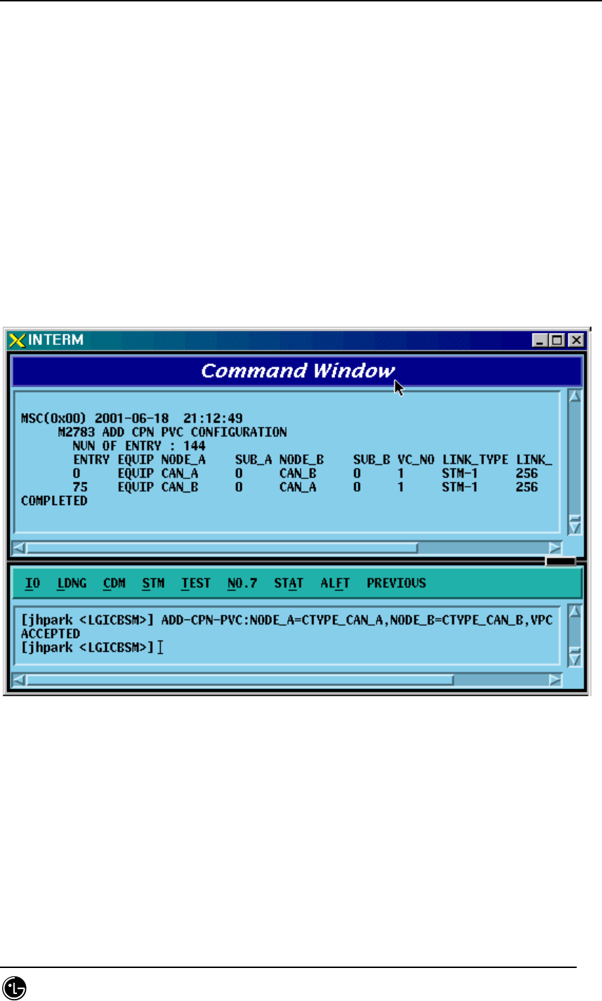
4.3.8.34. CAN PVC Configuration Addition
• Command ADD-CAN-PVC :NODE_A=a ,NODE_B=b ,VPCI_A=c ,VPCI_B=d
[,NO_VC=e] ;
• Input ADD-CAN-PVC: NODE_A=CTYPE_BSM_A, NODE_B=CTYPE_CNP_A,
VPCL_A=0,VPCL_B=0;
• Output
Fig. 4.3-158 CAN PVC Configuration Addition Display

STAREX-IS BSM Manual
Page:375(877)
Issue:1.
0
SMD-011-PMA210
4.3.8.35. CAN PVC Configuration Deletion
• Command RMV-CAN-PVC :INDEX=a;
• Input RMV-CAN-PVC: INDEX=0;
• Output
Fig. 4.3-159 CAN PVC Configuration Deletion Display
STAREX-IS BSM Manual
Page:376(877)
Issue:1.
0
SMD-011-PMA210
4.3.8.36. CPN PVC Configuration Addition
• Command ADD-CPN-PVC :NODE_A=a ,NODE_B=b ,VPCI_A=c ,VPCI_B=d
[,NO_VC=e] ;
• Input ADD-CPN-PVC:NODE_A=CTYPE_CAN_A, NODE_B=CTYPE_CAN_B,
VPCI_A=0, VPCI_B=0;
• Output
Fig. 4.3-160 CPN PVC Configuration Addition Display
STAREX-IS BSM Manual
Page:377(877)
Issue:1.
0
SMD-011-PMA210
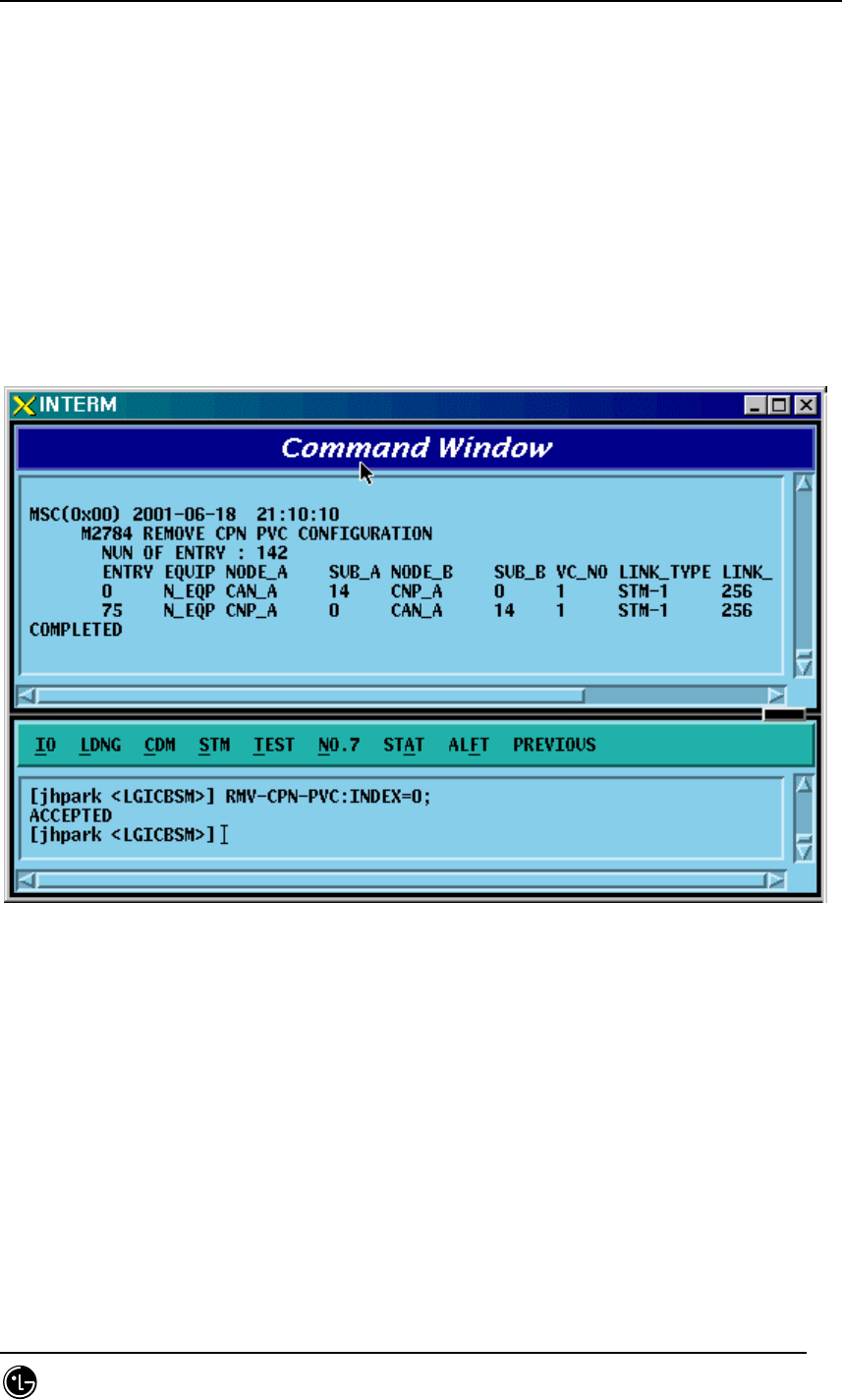
4.3.8.37. CPN PVC Configuration Deletion
• Command RMV-CPN-PVC :INDEX=a;
• Input RMV-CPN-PVC: INDEX=0;
• Output
Fig. 4.3-161 CPN PVC Configuration Deletion Display
STAREX-IS BSM Manual
Page:378(877)
Issue:1.
0
SMD-011-PMA210
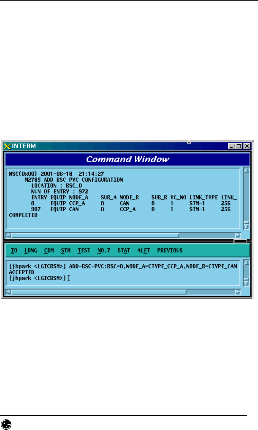
4.3.8.38. BSC PVC Configuration Addition
• Command ADD-BSC-PVC :BSC=a ,NODE_A=b ,NODE_B=c ,VPCI_A=d ,VPCI_B=e
[,NO_VC=f];
• Input ADD-BSC-PVC:BSC=0, NODE_A=CTYPE_CCP_A, NODE_B=CTYPE_CCP_B,
VPCI_A=0, VPCI_B=0;
• Output
Fig. 4.3-162 BSC PVC Configuration Addition Display
STAREX-IS BSM Manual
Page:379(877)
Issue:1.
0
SMD-011-PMA210
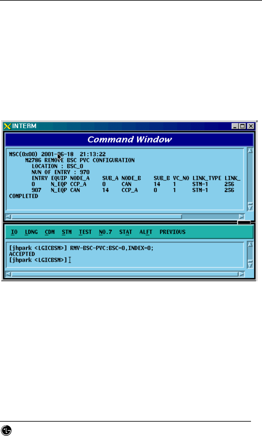
4.3.8.39. BSC PVC Configuration Deletion
• Command RMV-BSC-PVC :BSC=a ,INDEX=b;
• Input RMV-BSC-PVC:BSC=0, INDEX=0;
• Output
Fig. 4.3-163 BSC PVC Configuration Deletion Display
STAREX-IS BSM Manual
Page:380(877)
Issue:1.
0
SMD-011-PMA210
4.4. STATUS COMMAND
4.4.1 PROCESSOR STATUS CONTROL
Table 4.4-1 Processor Status LIST
Status Types Definition
NORM NORMAL
ABNM Abnormal
DCPY Dual Copy
LDNG StandBy Loading
NORM(OLD) Normal (After StandBy Loading, Old version)
NORM(NEW) Normal (After StandBy Loading, New version)
ABN_K Abnormal with Keep Alive Fault
ABN_I Abnormal with Process Isolation
UNDEF Undefined Status
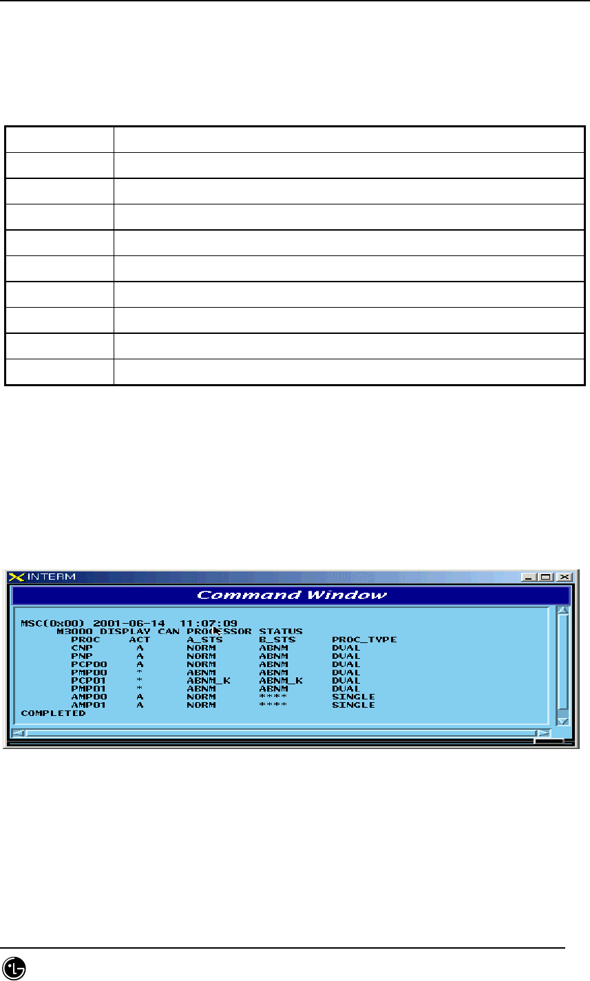
4.4.1.1. BSM CAN PROCESSOR STATUS DISPLAY COMMAND
Function to display processor status inserted in CAN.
Command : DIS-CAN-PRC;
Input : DIS-CAN-PRC;
Fig. 4.4-1 Result of CAN Processor Status Display Command
STAREX-IS BSM Manual
Page:381(877)
Issue:1.
0
SMD-011-PMA210
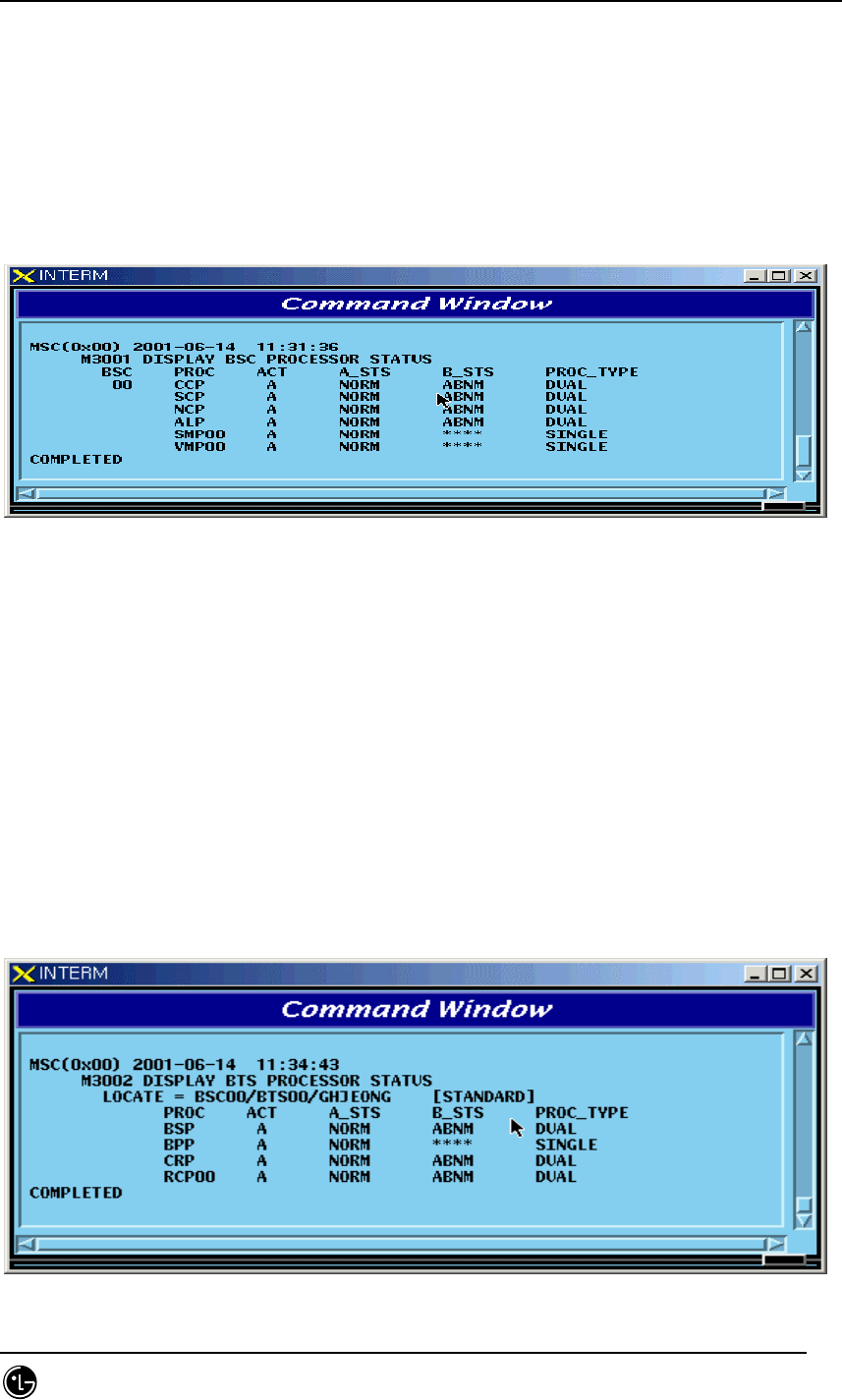
4.4.1.2. BSC Processor Status Display Command
Function to display Processor status inserted in BSC.
Command : DIS-BSC-PRC[:BSC=a];
a : BSC Number(0~11)
Input : DIS-BSC-PRC:BSC=0;
Fig. 4.4-2 Result of BSC Processor Status Display
4.4.1.3. Status Display Command of BTS Processor
Function to display operation status of processors mounted in all the BTSs within the
corresponding BSC or in each BTS
Command : DIS-BTS-STS:BSC=a[,BTS=b];
a:BSC Number (0~11)
b:BTS Number (0~47)
Input : DIS-BTS-STS:BSC=0,BTS=0;
Output
Fig. 4.4-3 Result of BTS Processor Status Display Command
STAREX-IS BSM Manual
Page:382(877)
Issue:1.
0
SMD-011-PMA210
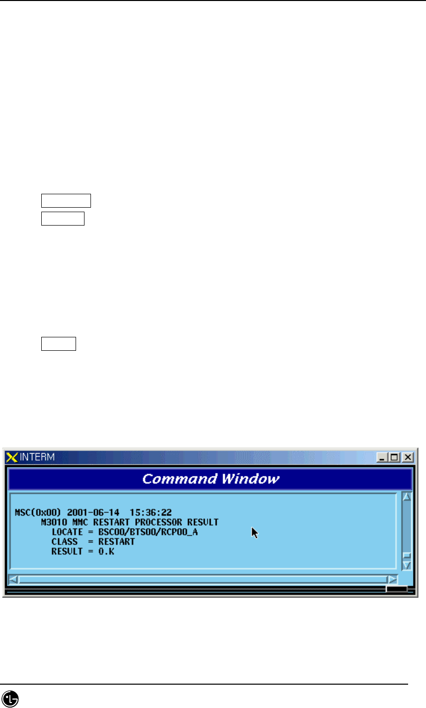
4.4.1.4. Processor Restart Command
Function to restart Processors
• Command : RST-PRC[:BSC=a][,BTS=b],RANGE=c,SIDE=d,CLS=e;
a : BSC Number (0~11)
b : BTS Number (0~47)
c : Scope of restart(All the Processors of CCP, PNP,NCP,PCP., etc.)
d : Side to restart (A,B,BOTH)
e : Class (RESTART, REBOOT, FLASH)
RESTART : Restart O/S and receive loading of PLD only.
REBOOT : It executes BOOTER. In case of the processors equipped with Flash
ROM, they check upper level processors and version of each block. If they are
different, they receive loading from the upper level processors. However, if
they are the same, they do not receive loading from the upper level
processors. The processors with no Flash ROM receive loading from the upper
level processors without checking version.
. For reference, Active Side before and after reboot does not change.
FLASH : Delete Flash content of the Processor with Flash ROM equipped and
reboot it to receive loading of all the files from the upper level Processor. For
reference, Active Side before and after Flash Reboot changes.
Input : RST-PRC:BSC=0,BTS=0,RANGE=RCP00,SIDE=A,CLS=RESTART;
Fig. 4.4-4 Result of Processor Restart Command
STAREX-IS BSM Manual
Page:383(877)
Issue:1.
0
SMD-011-PMA210
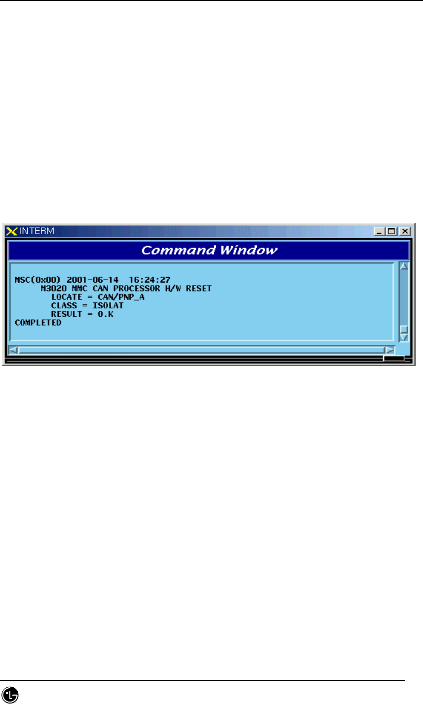
4.4.1.5. CAN Processor H/W RESET(ISOLATION) COMMAND
Function to reset CAN Processor H/W.
Command : RMT-CAN-PRC:PROC=a,SIDE=b,CLS=c;
a: Processor Name : CNP,PNP,PCP,PMP
b: Side : A,B
c: CLASS : HARDRST,ISOLAT,UNISOL
HARDRST : Function to reset Processor on H/W Level (using Register Setting).
ISOLAT : Function to isolate Processor on H/W Level (maintaining Status of RESET)
UNISOL : Function to release the isolation
Input : RMT-CAN-PRC:PROC=PNP,SIDE=A,CLS=ISOLAT;
Fig. 4.4-5 CAN Processor H/W Command Result
4.4.1.6. BSC Processor H/W RESET(ISOLATION) COMMAND
Function to reset BSC Processor H/W.
Command : RMT-BSC-PRC:BSC=a,PROC=b,[SIDE=c],CLS=d;
a: BSC Number
b: Processor Name : CCP,NCP,SCP,ALP,SMP,VMP
c: Side : A,B
d: CLASS : HARDRST,ISOLAT,UNISOL
HARDRST : Function to RESET Processor on H/W Level (using Register Setting).
ISOLAT : Function to isolate Processor on H/W Level (RESET Status maintained)
UNISOL : Function to release isolation
STAREX-IS BSM Manual
Page:384(877)
Issue:1.
0
SMD-011-PMA210
Input : RMT-BSC-PRC:BSC=0,PROC=NCP,SIDE=A,CLS=ISOLAT;
Fig. 4.4-6 BSC Processor H/W Command Result
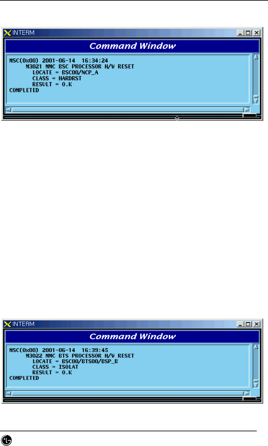
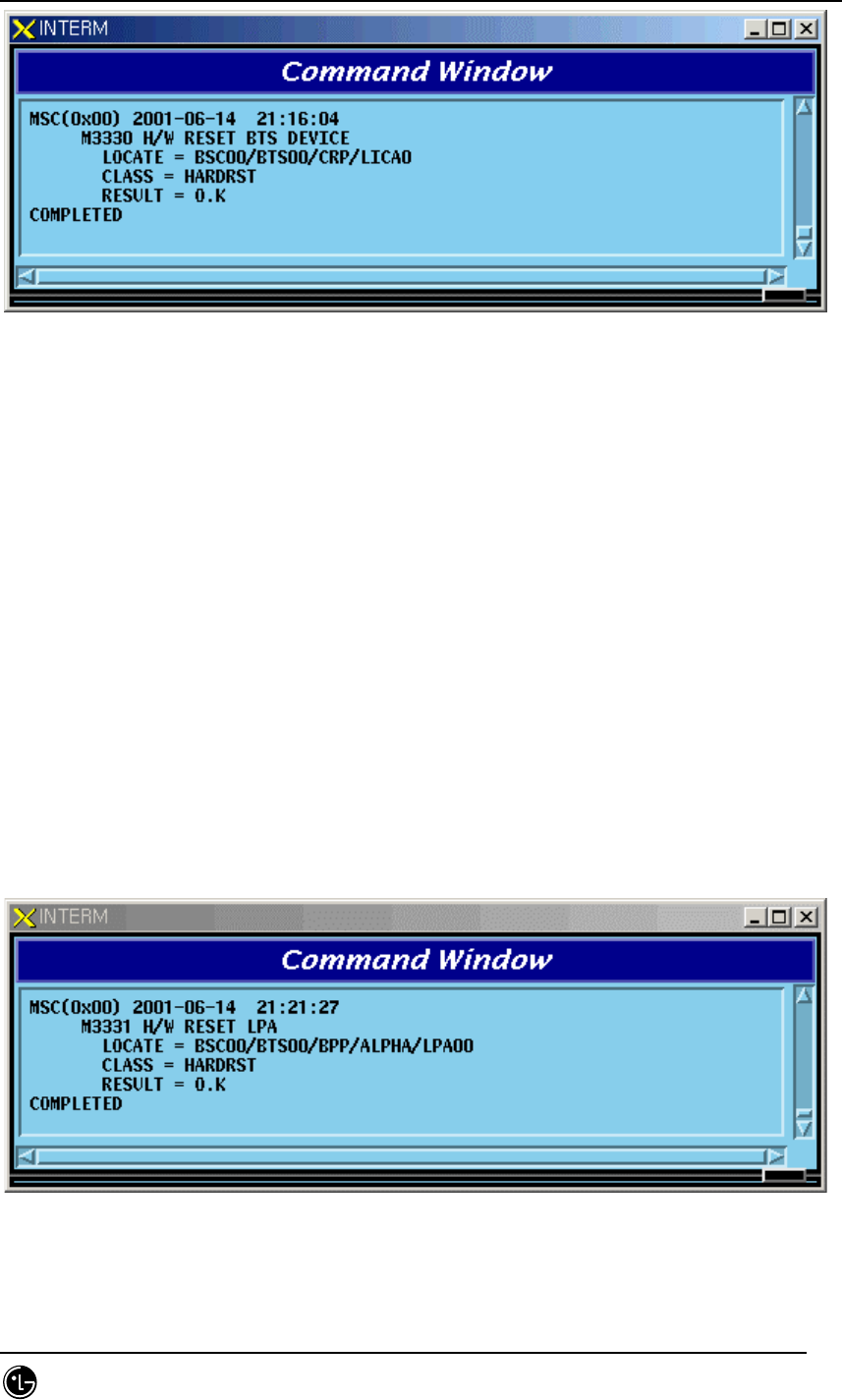
4.4.1.7. BTS Processor H/W RESET(ISOLATION) COMMAND
Function to BSC Processor H/W.
Command : RMT-BTS-PRC:BSC=a,BTS=b,PROC=c,[SIDE=d],CLS=e;
a: BSC Number
b: BTS Number
c: Processor Name : BSP,BPP,CRP,RCP(00~05)
d: Side : A,B
e: CLASS : HARDRST,ISOLAT,UNISOL
HARDRST : Function to RESET Processor on H/W Level (using Register Setting).
ISOLAT : Function to isolate Processor on H/W Level (RESET Status maintained)
UNISOL : Function to release isolation
Input : RMT-BTS-PRC:BSC=0,BTS=0,PROC=BSP,SIDE=A,CLS=ISOLAT;
Fig. 4.4-7 BTS Processor H/W RESET(ISOLATION) Command Display Result
STAREX-IS BSM Manual
Page:385(877)
Issue:1.
0
SMD-011-PMA210
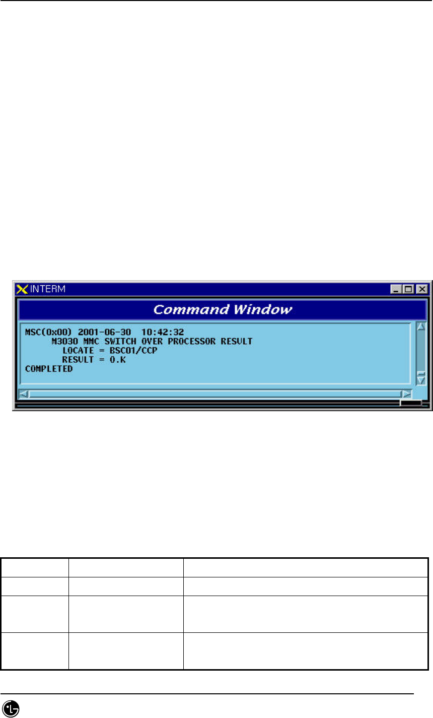
4.4.1.8. Processor Switch Over(Switch) Command
Function to Switch over Processor.
Switching Over Command is executed for duplicated Processors and is performed only
when both sides of Processors are in a normal status.
Command : SWT-PRC [:BSC=a] [,BTS=b] ,PROC=c;
a: BSC Number
b: BTS Number
c: Processor Name : CNP, PNP, PCP00, PCP01,PCP02, PMP00, PMP01,PMP02,
CCP, NCP, SCP,ALP, BSP, CRP, RCP00, RCP01, RCP02, RCP03,RCP04, RCP05
Input : SWT-PRC :BSC=1 ,PROC=CCP;
Fig. 4.4-8 Processor Switch Over(Switch) Command Display Result
4.4.2. Network Status Control
Table 4.4-2 Network Node Status LIST
Status Types Definition Description
NORM Normal Normal Operation
NOR_A Normal Act While normally operated, Act Status is
maintained (Duplicated node)
NOR_S Normal Standby While normally operated, Standby Status is
maintained (Duplicated node)
STAREX-IS BSM Manual
Page:386(877)
Issue:1.
0
SMD-011-PMA210
ABN_D Abnormal Deletion card is removed
ABN_F Abnormal Fault Local Fault occurred
ABN_M Abnormal MMC Block Blocked Status by User’s MMC
INIT Initial
Even equipped to PLD, a processor managing the
corresponding device does not normally operate
until now
AB_OB Abnormal Online Block
Based on judgment that a normal call is
impossible due to faults in other devices, the
corresponding device is blocked
N_EQP Not Equipped Card Type is not defined in PLD
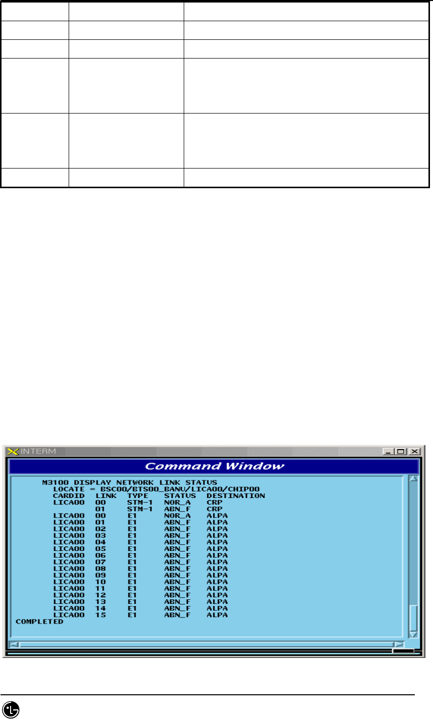
4.4.2.1. Network Status Display Command
Function to display the BSS Network status.
Command : DIS-NET-STS: [BSC=a],[BTS=b],SHELF=c,CARD=d,ID=e,[CHIP=f];
a : BSC Number
b : BTS Number
c : SHELF NAME(CAMU,CAMDU,ASMU,ALSU,BANU)
d : CARD NAME(ASCA,ASIA,AOTA,ATSA,ALMA,LICA)
e : CARD ID(0~3)
f : CHIP Number(0~1)
Input : DIS-NET-STS:BSC=0,BTS=0,SHELF=BANU,CARD=LICA,ID=0;
STAREX-IS BSM Manual
Page:387(877)
Issue:1.
0
SMD-011-PMA210
Fig. 4.4-9 Result of Network Status Display Command
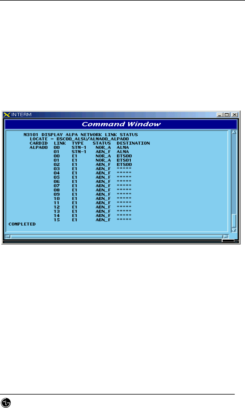
4.4.2.2. ALPA Network Status Display
Function to display the ALPA Network status.
Command : DIS-ALPA-STS:BSC=a,ALMA=b,ALPA=c;
a : BSC Number(0~11)
b : ALMA ID(0~1)
c : ALPA ID(0~4)
Input : DIS-ALPA-STS:BSC=0,ALMA=0,ALPA=0;
Fig. 4.4-10 Result of ALPA Network Status Display
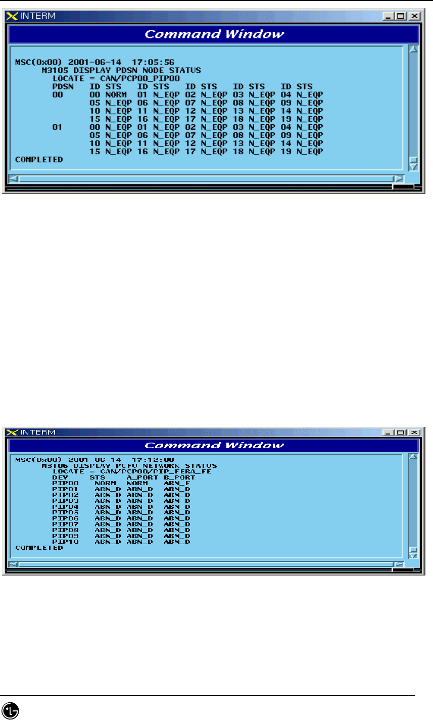
4.4.2.3. PDSN NODE Status Display
Function to display the PDSN NODE Network status
Command : DIS-PDSN-STS:SHELF=a,PIP=b;
a: SHELF(PCP(00~02),PMP(00~02))
b: PIP(0~10)
Input : DIS-PDSN-STS:SHELF=PCP00,PIP=0;
STAREX-IS BSM Manual
Page:388(877)
Issue:1.
0
SMD-011-PMA210
Fig. 4.4-11 Result of PDSN NODE Status Display
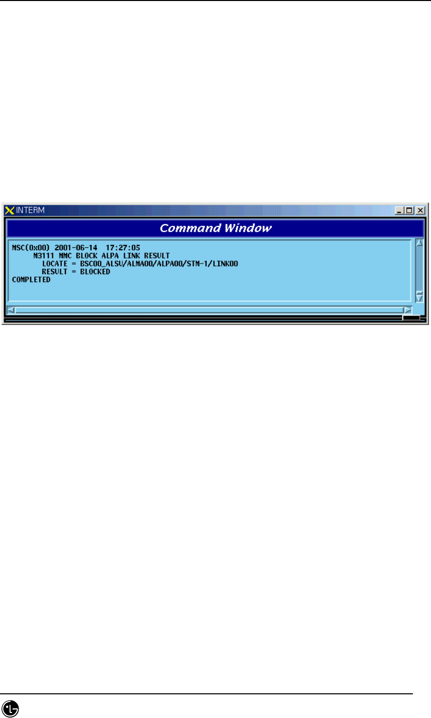
4.4.2.4. PCFU Network Status Display Command
Function to display the PCFU Network Status
Command : DIS-PCF-NET:PROC=a,TYPE=b;
a: PCP(00~02),PMP(00~02)
b: PIP_FERA,FETA_PDSN
Input : DIS-PCF-NET:PROC=PCP00,TYPE=PIP_FERA;
Fig. 4.4-12 Result of PCFU Network Status Display Command
STAREX-IS BSM Manual
Page:389(877)
Issue:1.
0
SMD-011-PMA210
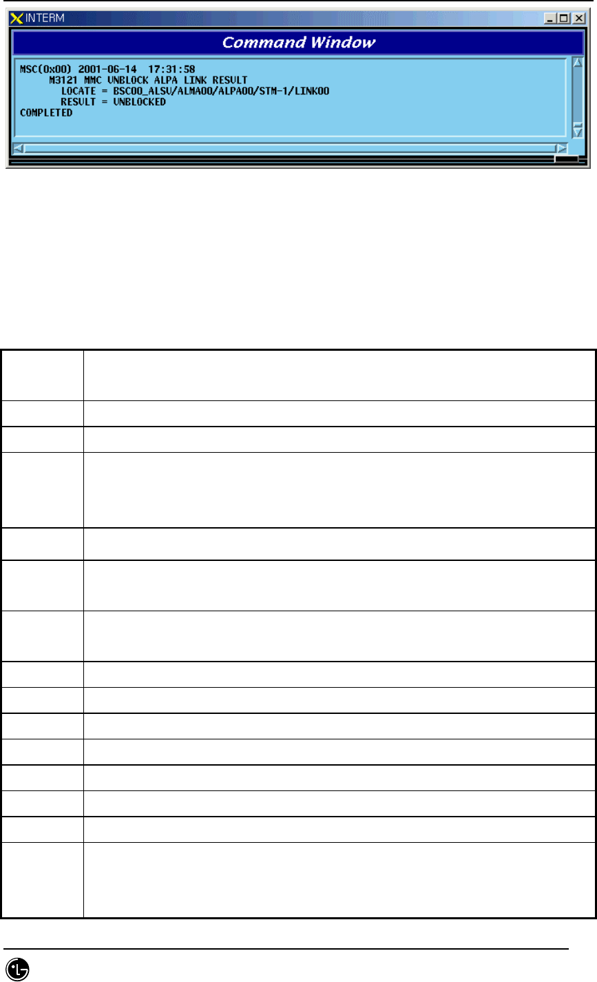
4.4.2.5. ALPA Network Block Command
Function to block the ALPA Network.
Command : BLK-ALPA:BSC=a,ALMA=b,ALPA=c,[TYPE=d],[LINK=e];
a: BSC Number(00~11)
b: ALMA ID(0~1)
c: ALPA ID(0~4)
d: TYPE(STM_1,E1)
e: LINK(0~15)
Input : BLK-ALPA:BSC=0,ALMA=0,ALPA=0,TYPE=STM_1,LINK=0;
Fig. 4.4-13 Result of ALPA Network Block Command
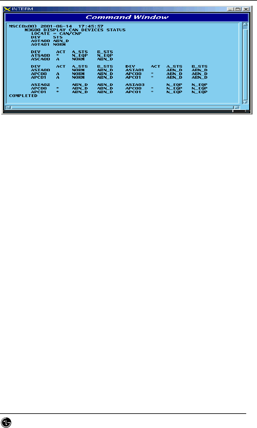
4.4.2.6. UNBlock Command
Function to unblock the ALPA Network.
Command : UBLK-ALPA:BSC=a,ALMA=b,ALPA=c,[TYPE=d],[LINK=e];
a: BSC Number(00~11)
b: ALMA ID(0~1)
c: ALPA ID(0~4)
d: TYPE(STM_1,E1)
e: LINK(0~15)
Input : UBLK-ALPA:BSC=0,ALMA=0,ALPA=0,TYPE=STM_1,LINK=0;
STAREX-IS BSM Manual
Page:390(877)
Issue:1.
0
SMD-011-PMA210
Fig. 4.4-14 Result of ALPA Network UNBlock Command
4.4.3. Can Device Status Control
Table 4.4-3 DEVICE Status List
Status
Types
Definition
NORM Normal
ABN_D Abnormal Deletion (Even equipped to PLD, it is in the Status of Removal)
ABN_F Abnormal Fault(Status that normal operation is impossible due to fault in
Device)
(Test: As a result of DSP Chip Hardware Test, NOK occurs)
ABN_M Abnormal MMC Block
INIT Initial (Even equipped to PLD, a processor managing the corresponding
device does not operate normally until now)
AB_OB Abnormal Online Block (Based on judgment that a normal call is impossible
due to faults in other devices, the appropriate device is blocked)
IDLE Even if it is normal, call resources are not allocated (CE, VCE)
BUSY normal and call resources are allocated (CE, VCE)
N_EQP Status defined as Not Equipped to PLD
READY Even if not defined in PLD, Device is inserted
UNDEF Status that un-defined status is inserted
ABN_I Status being separated as H/W Reset
ABN_B BER Test Status by User
NOR_PB In case that call exists when CHC, Chip is blocked, it indicates the status that
awaits until a call is terminated
it indicates, the Status that waits for the call termination in order to perform

STAREX-IS BSM Manual
Page:391(877)
Issue:1.
0
SMD-011-PMA210
the Vocoder test.
REDNCY In duplicated Device, it indicates Redundancy Status of Standby side(FETA
Only)
CB_OPN For device that is managed only as fault, it is the case that is opened to Fault
Cable
CLK_F During Vocoder Channel test, as a result of Timing-Module test, NOK
occurred (Test Only)
TSW_F As a result of TSLU Loopback test, NOK is occurred (Test Only)
ABN_AT Status in which Vocoder is put to Automatic(Online) test (Test Only)
ABN_MT Status in which Vocoder Manual(Ondemand) is put to test (Test Only)
QAT0_F As a result of QCELP Algorithm test during Vocoder channel test, NOK
occurred in State 0 (Test Only)
QAT1_F As a result of QCELP Algorithm test during Vocoder channel test, NOK
occurred in State 1 (Test Only))
QAT2_F As a result of QCELP Algorithm test during Vocoder channel test, NOK
occurred in State 2 (Test Only)
QAT3_F As a result of QCELP Algorithm test during Vocoder channel test, NOK
occurred in State 3 (Test Only)
VPLB_F As a result of VCPA Loopback test during Vocoder channel test, NOK
occurred (Test Only)
VMLB_F As a result of VCMA Loopback test during Vocoder channel test, NOK
occurred (Test Only)
VLLB_F As a result of VLIA Loopback test during Vocoder channel test, NOK occurred
(Test Only)
4.4.3.1. CAN Device Status Display Command
Function to display Device(BOARD) Status mounted to CAN
Command : DIS-CAN-DEV:PROC=a;
a : CNP,PNP,PCP(00~02)
Input : DIS-CAN-DEV:PROC=CNP;
STAREX-IS BSM Manual
Page:392(877)
Issue:1.
0
SMD-011-PMA210
Fig. 4.4-15 Result of CAN Device Status Display Command
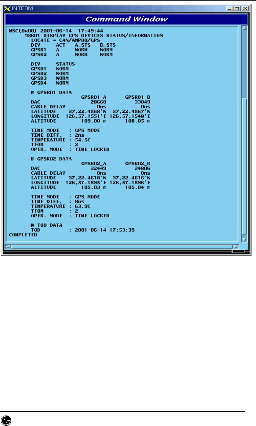
4.4.3.2. GPS(CAN) Status Display Command
Function to display Device and Information of CAN GPS.
Command : DIS-GPS-STS:TYPE=a;
a : ALL,GPS_DEV,GPS_INFO
Input : DIS-GPS-STS:TYPE=ALL;
STAREX-IS BSM Manual
Page:393(877)
Issue:1.
0
SMD-011-PMA210
Fig. 4.4-16 Result of GPS(CAN) Status Display Command
4.4.3.3. H/W RESET CAN DEVICE Command
Function to reset CAN Device on H/W Level
Command : RMT-CAN-DEV:PROC=a,DEV=b,ID=c,[SIDE=d],CLS=e;
a: Processor :CNP,PNP,PCP(00~02),PMP(00~02)
b: Device Name: ASCA,ASIA,AOTA,ATSA,PIP,FERA,FETA,BCRA
c: Device ID : 0~10
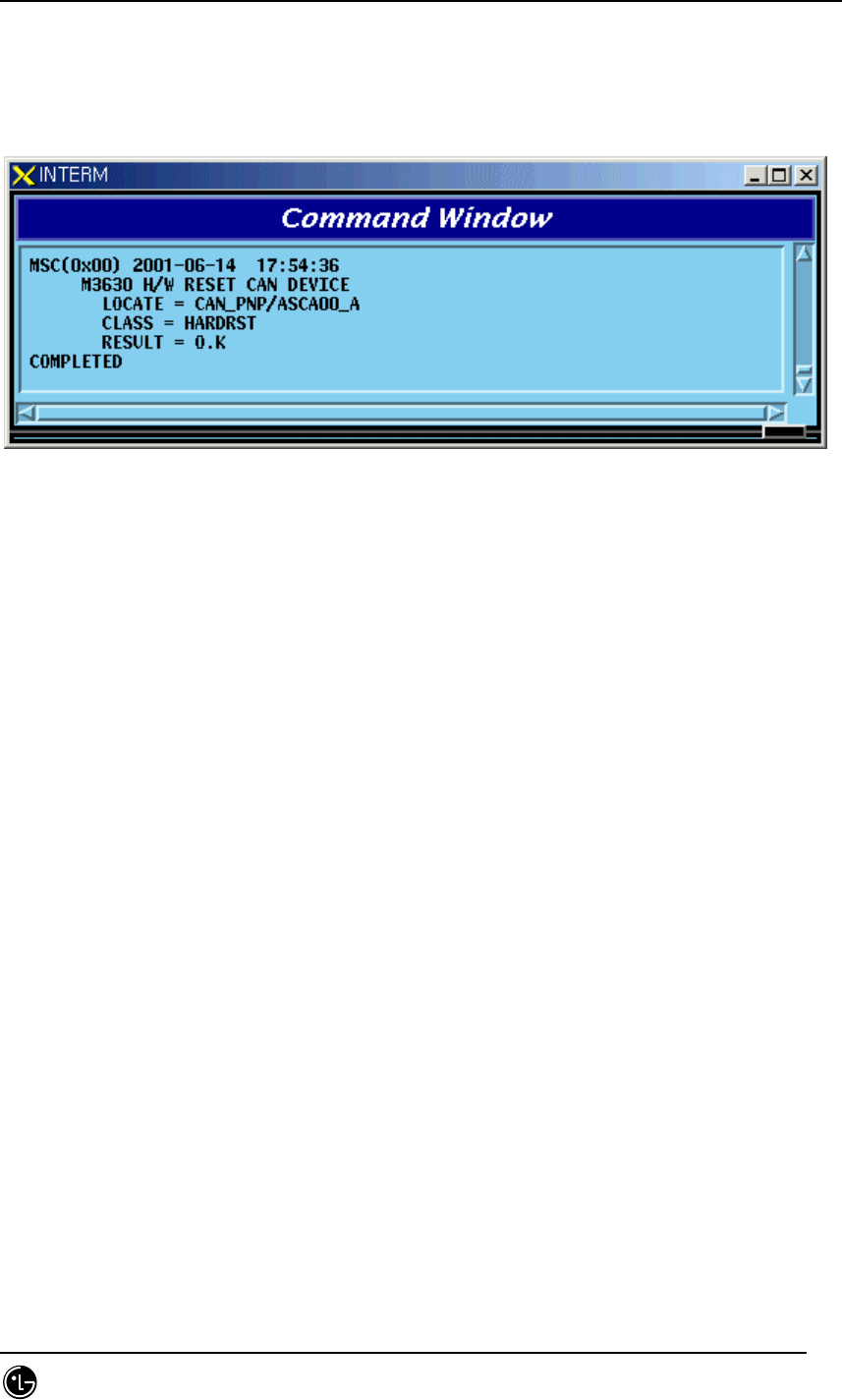
STAREX-IS BSM Manual
Page:394(877)
Issue:1.
0
SMD-011-PMA210
d: SIDE:A_SIDE,B_SIDE
e: CLASS : HARDRST,ISOLAT,UNISOL
Input : RMT-CAN-DEV:PROC=PNP,DEV=ASCA,ID=0,SIDE=A_SIDE,CLS=HARDRST;
Fig. 4.4-17 Result of H/W RESET CAN DEVICE Command
4.4.4. BSC Device Status Control
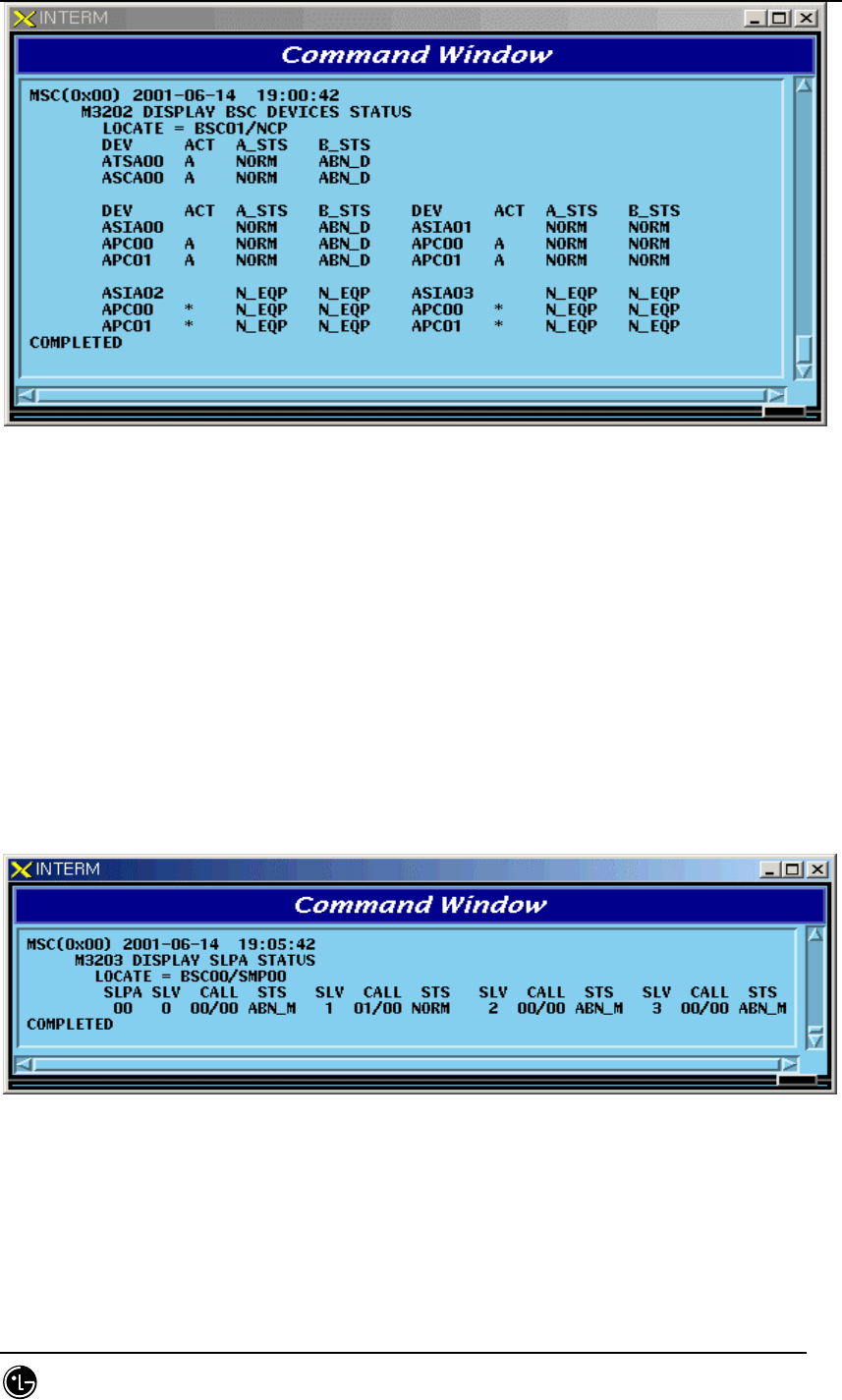
4.4.4.1. BSC Device Status Display Command
Function to display Status of various Boards mounted to BSC
Command : DIS-BSC-DEV:BSC=a,PROC=b;
a : BSC Number(00~11)
b : PROC Name(NCP,SCP,ALP,SMP(00~04),VMP(00~08))
Input : DIS-BSC-DEV:BSC=1,PROC=NCP;
STAREX-IS BSM Manual
Page:395(877)
Issue:1.
0
SMD-011-PMA210
Fig. 4.4-18 Result of BSC Device Status Display
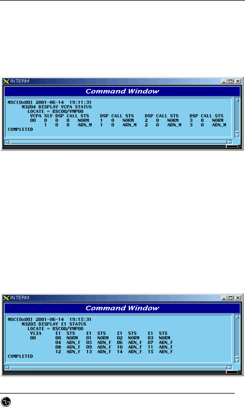
4.4.4.2. SLPA Status Display Command
Function to display the SLPA Status
Command : DIS-SLPA-STS:BSC=a,SMP=b,[SLPA=c];
a : BSC Number(00~11)
b : SMP Number(00~04)
c : SLPA Number(00~17)
Input : DIS-SLPA-STS:BSC=0,SMP=0,SLPA=0;
Fig. 4.4-19 Result of SLPA Status Display Command
4.4.4.3. VCPA Status Display Command
Function to display the VCPA Status
STAREX-IS BSM Manual
Page:396(877)
Issue:1.
0
SMD-011-PMA210
Command : DIS-VCPA-STS:BSC=a,VMP=b,[VCPA=c];
a : BSC Number(00~11)
b : VMP Number(00~07)
c : VCPA Number(00~15)
Input : DIS-VCPA-STS:BSC=0,VMP=0,VCPA=0;
Fig. 4.4-20 Result of VCPA Status Display Command
4.4.4.4. E1 LINK Status Display Command
Function to display E1 Link Status of VLIA
Command : DIS-E1-STS:BSC=a,VMP=b,[VLIA=c];
a : BSC Number(00~11)
b: VMP Number(00~07)
c: VLIA Number(00~01)
Input : DIS-E1-STS:BSC=0,VMP=0,VLIA=0;
STAREX-IS BSM Manual
Page:397(877)
Issue:1.
0
SMD-011-PMA210
Fig. 4.4-21 Result of E1 LINK Status Display Command
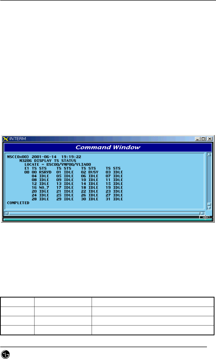
4.4.4.5. TS Network LINK Status Display Command
Function to display the Status of TS Network Link of VLIA.
Command : DIS-TS-STS:BSC=a,VMP=b,VLIA=c,E1=d;
a : BSC Number(00~11)
b : VMP Number(00~07)
c : VLIA Number(00~15)
d : E1 Number(00~15)
Input : DIS-TS-STS:BSC=0,VMP=0,VLIA=0,E1=0;
Fig. 4.4-22 Result of TS Network LINK Status Display Command
4.4.4.6. VCE(Vocoder Channel Element) Status Display Command
Table 4.4-4 Vocoder Channel Element Status LIST
Status Types Definition Description
IDLE Idle Normal status without a Call
8K_Qcelp 8k Qcelp Call 8k QCELP Call Seized Status
8K_EVRC 8k EVRC Call 8k EVRC Call Seized Status
STAREX-IS BSM Manual
Page:398(877)
Issue:1.
0
SMD-011-PMA210
13K_Qcelp 13k Qcelp Call 13k QCELP Call Seized Status
13K_EVRC 13k EVRC Call 13k EVRC Call Seized Status
ABN_M Abnormal MMC Block Blocked Status by user’s MMC
UNDEF Undefined Status Status with Input of undefined Status
Function to display the Channel Element Status of VCE.
Command : DIS-VCE-STS:BSC=a,VMP=b,[VCPA=c];
a : BSC Number(00~11)
b : VMP Number(00~07)
c: VCPA Number(00~15)
Input : DIS-VCE-STS:BSC=0,VMP=0,VCPA=0;
Fig. 4.4-23 Result of VCE(Vocoder Channel Element) Status Display Command
4.4.4.7. SLPA BLOCK Command
Function to block SLPA.
Command : BLK-SLPA:BSC=a,SMP=b,SLPA=c,[SLV=d];
a : BSC Number(00~11)
b : SMP Number(00~04)
c : SLPA Number(00~17)
d : SLV Number(00~03)
Input : BLK-SLPA:BSC=0,SMP=0,SLPA=0,SLV=0;
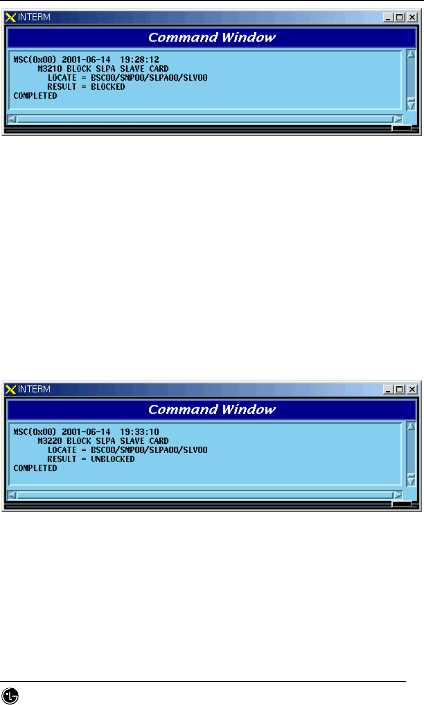
STAREX-IS BSM Manual
Page:399(877)
Issue:1.
0
SMD-011-PMA210
Fig. 4.4-24 Result of SLPA BLOCK Command
4.4.4.8. SLPA UNBLOCK Command
Function to unblock SLPA.
Command : UBLK-SLPA:BSC=a,SMP=b,SLPA=c,[SLV=d];
a : BSC Number(00~11)
b : SMP Number(00~04)
c : SLPA Number(00~17)
d : SLV Number(00~03)
Input : UBLK-SLPA:BSC=0,SMP=0,SLPA=0,SLV=0;
Fig. 4.4-25 Result of SLPA UNBLOCK Command
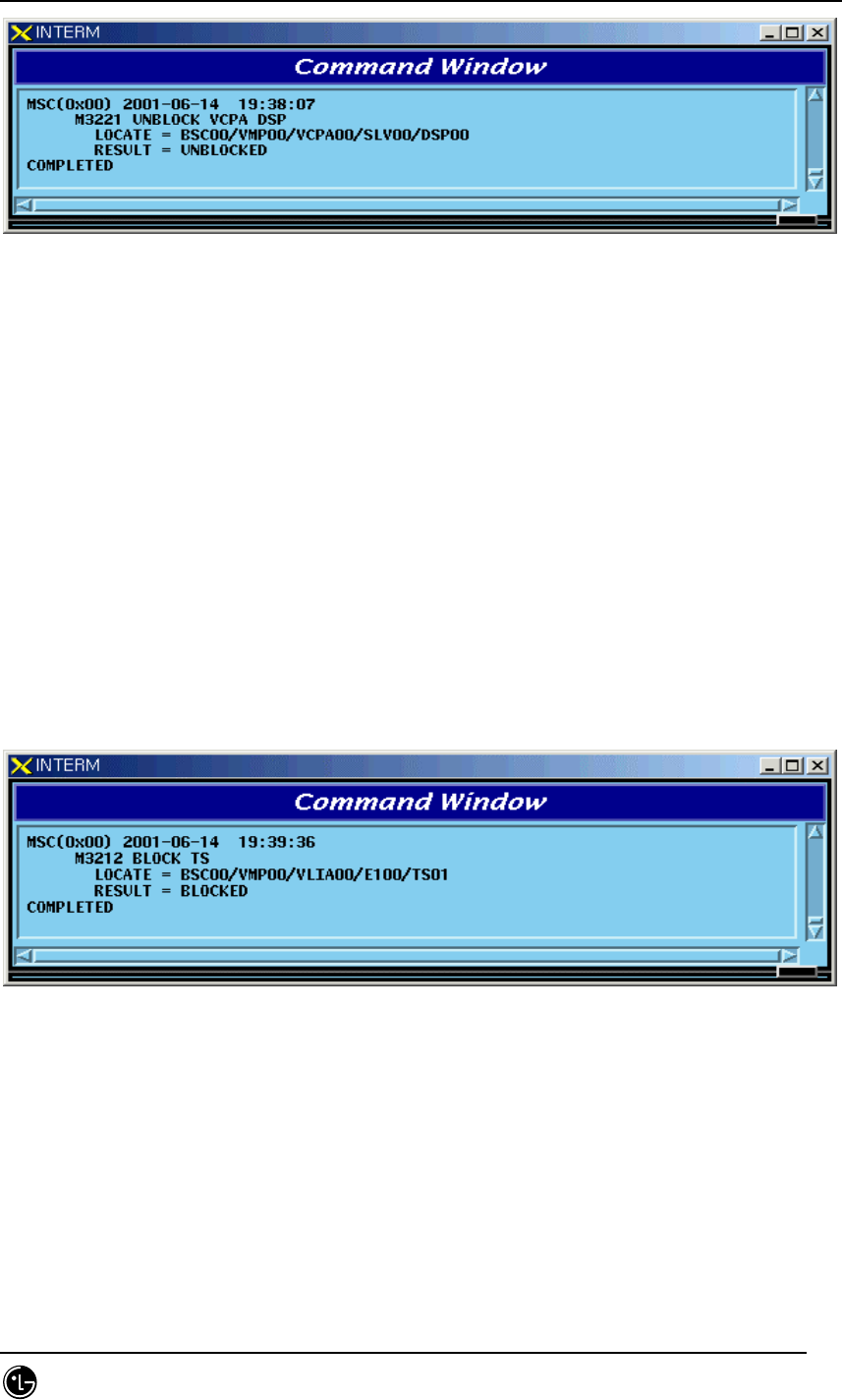
4.4.4.9. VCPA BLOCK Command
Function to block VCPA.
Command : BLK-VCPA:BSC=a,VMP=b,VCPA=c,[SLV=d],[DSP=e];
a : BSC Number(00~11)
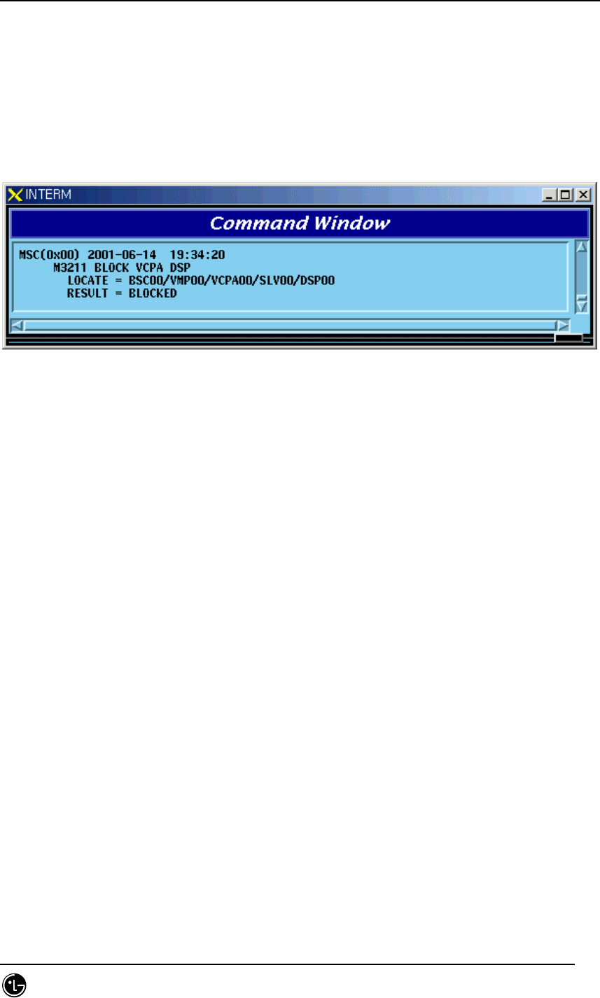
STAREX-IS BSM Manual
Page:400(877)
Issue:1.
0
SMD-011-PMA210
b : VMP Number(00~07)
c : VCPA Number(00~15)
d : SLV Number(00~01)
e : DSP Number(00~03)
Input : BLK-VCPA:BSC=0,VMP=0,VCPA=0,SLV=0,DSP=0;
Fig. 4.4-26 Result of VCPA BLOCK Command
4.4.4.10. VCPA UNBLOCK Command
Function to unblock VCPA
Command : UBLK-VCPA:BSC=a,VMP=b,VCPA=c,[SLV=d],[DSP=e];
a : BSC Number(00~11)
b : VMP Number(00~07)
c : VCPA Number(00~15)
d : SLV Number(00~01)
e : DSP Number(00~03)
Input : UBLK-VCPA:BSC=0,VMP=0,VCPA=0,SLV=0,DSP=0;
STAREX-IS BSM Manual
Page:401(877)
Issue:1.
0
SMD-011-PMA210
Fig. 4.4-27 Result of VCPA UNBLOCK Command
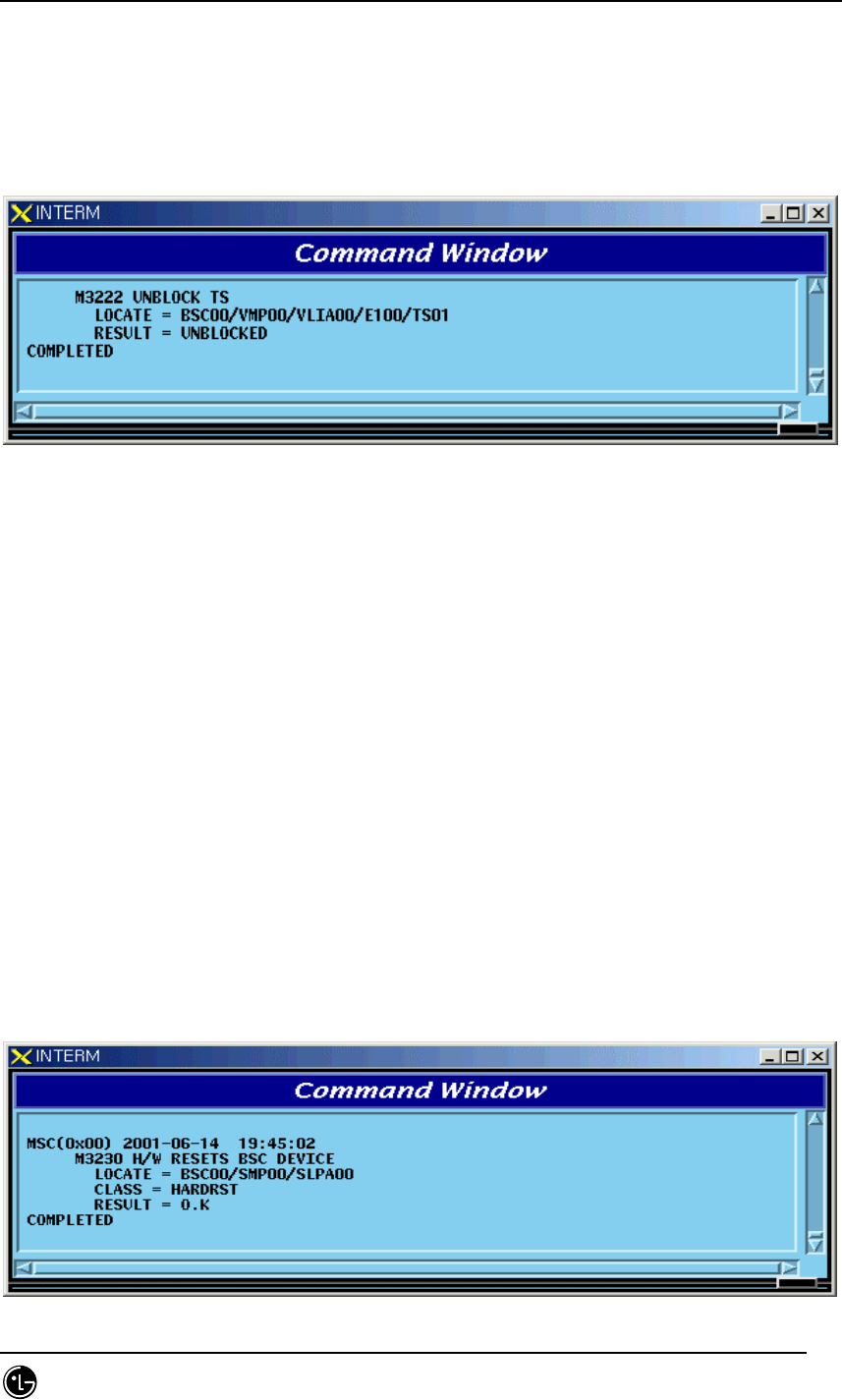
4.4.4.11. VLIA BLOCK Command
Function to block VLIA.
Command : BLK-VLIA:BSC=0,VMP=0,VLIA=0,[E1=0],[TS=1];
a : BSC Number(00~11)
b : VMP Number(00~07)
c : VLIA Number(0~1)
d : E1 Number(00~15)
e : TS Number(00~31)
Input : BLK-VLIA:BSC=0,VMP=0,VLIA=0,E1=0,TS=1;
Fig. 4.4-28 Result of VLIA BLOCK Command
4.4.4.12. VLIA UNBLOCK Command
Function to unblock VLIA
Command : UBLK-VLIA:BSC=0,VMP=0,VLIA=0,[E1=0],[TS=1];
a : BSC Number(00~11)
b : VMP Number(00~07)
STAREX-IS BSM Manual
Page:402(877)
Issue:1.
0
SMD-011-PMA210
c : VLIA Number(0~1)
d : E1 Number(00~15)
e : TS Number(00~31)
Input : UBLK-VLIA:BSC=0,VMP=0,VLIA=0,E1=0,TS=1;
Fig. 4.4-29 Result of VLIA UNBLOCK Command
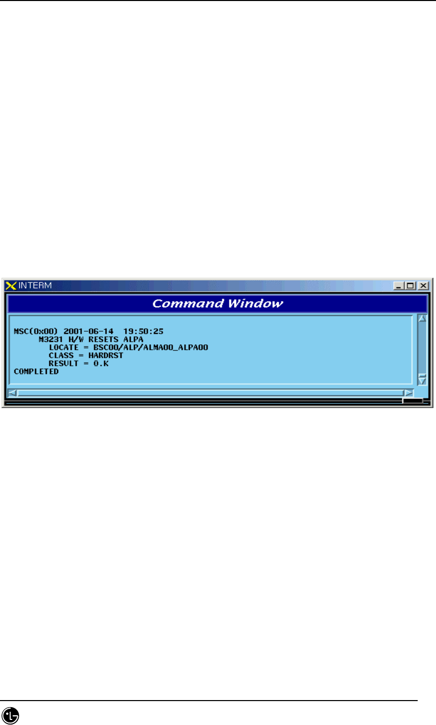
4.4.4.13. H/W RESET BSC Device Command
Function to reset BSC Device on H/W Level.
Command : RMT-BSC-DEV:BSC=a,PROC=b,DEV=c,ID=d,[SUBID=e],CLS=f;
a : BSC Number(00~11)
b : Processor Name(NCP,SCP,ALP,SMP(00~05),VMP(00~07))
c : Device Name(SLPA,VCPA,VLIA,STIA,ASCA,ASIA,AOTA,ATSA,ALMA)
d : Device ID(00~17)
e : Sub_id(A_SIDE,B_SIDE)
f : Class(HARDRST,ISOLAT,UNISOL)
Input : RMT-BSC-DEV:BSC=0,PROC=SMP00,DEV=SLPA,ID=0,CLS=HARDRST;
STAREX-IS BSM Manual
Page:403(877)
Issue:1.
0
SMD-011-PMA210
Fig. 4.4-30 Result of BSC Device H/W Reset Command
4.4.4.14. H/W RESET ALPA Command
Function to reset ALPA on H/W Level.
Command : RMT-ALPA:BSC=0,ALMA=0,ALPA=0,CLS=HARDRST;
a : BSC Number(00~11)
b : ALMA ID(0~1)
c : ALPA ID(0~4)
d : Class(HARDRST,ISOLAT,UNISOL)
Input : RMT-ALPA:BSC=0,ALMA=0,ALPA=0,CLS=HARDRST;
Fig. 4.4-31 Result of H/W RESET ALPA Command
4.4.5. Bts Device Status Control
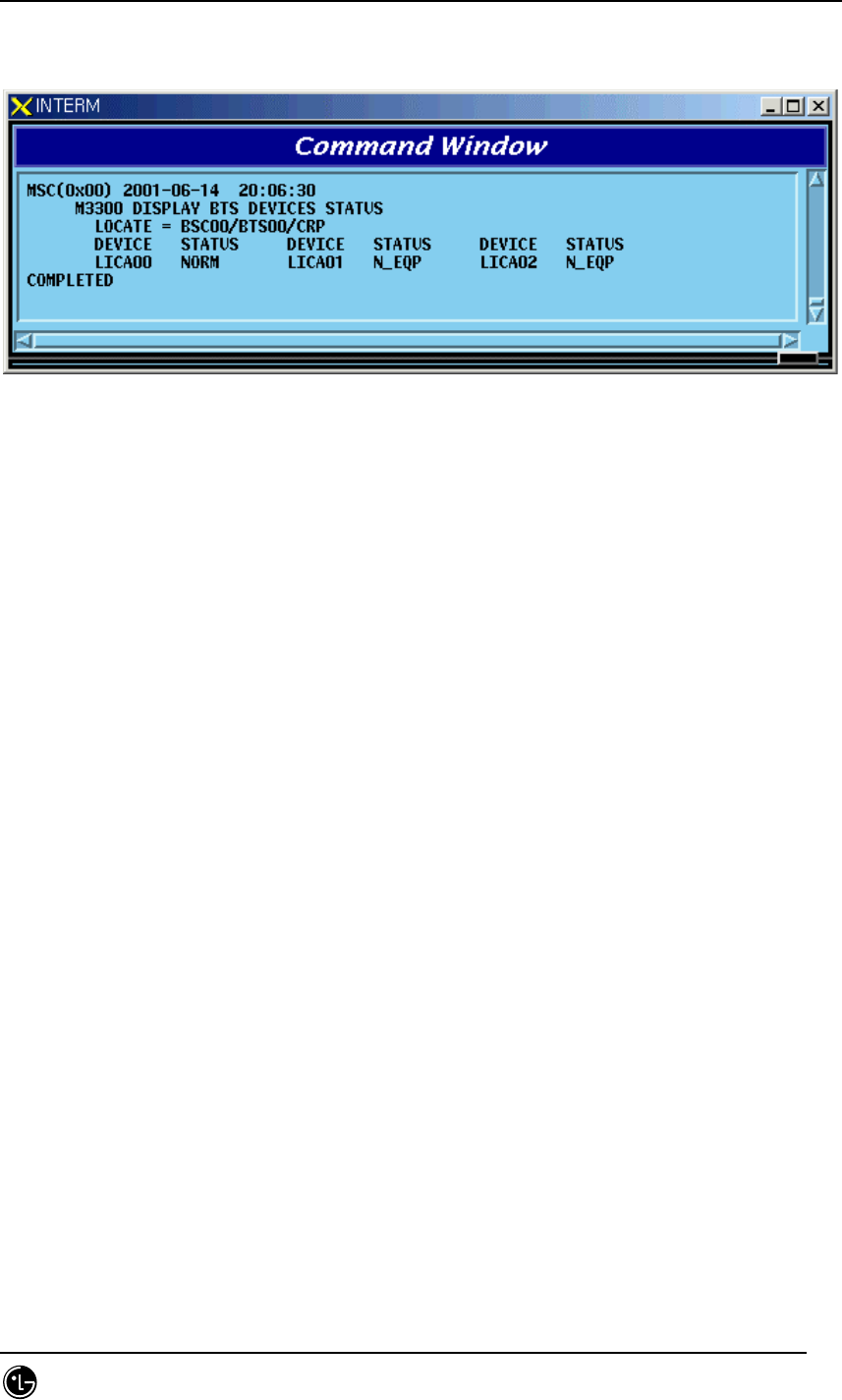
4.4.5.1. BTS Device Status Display Command
Function to display the BTS Device status
Command : DIS-BTS-DEV:BSC=a,BTS=b,PROC=c;
a : BSC Number(00~11)
b : BTS Number(00~47)
c : Processor Name(BSP,BPP,CRP,RCP(00~06)
STAREX-IS BSM Manual
Page:404(877)
Issue:1.
0
SMD-011-PMA210
Input : DIS-BTS-DEV:BSC=0,BTS=0,PROC=CRP;
Fig. 4.4-32 Result of BTS Device Status Display Command
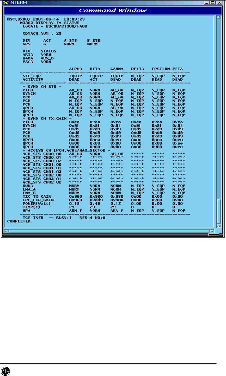
4.4.5.2. FA Status Display Command
Function to display FA Status.
Command : DIS-FA-STS:BSC=a,BTS=bFA=c;
a : BSC Number(00~11)
b : BTS Number(00~47)
c : FA Number(0~7)
Input : DIS-FA-STS:BSC=0,BTS=0,FA=0;
STAREX-IS BSM Manual
Page:405(877)
Issue:1.
0
SMD-011-PMA210
Fig. 4.4-33 Result of FA Status Display Command
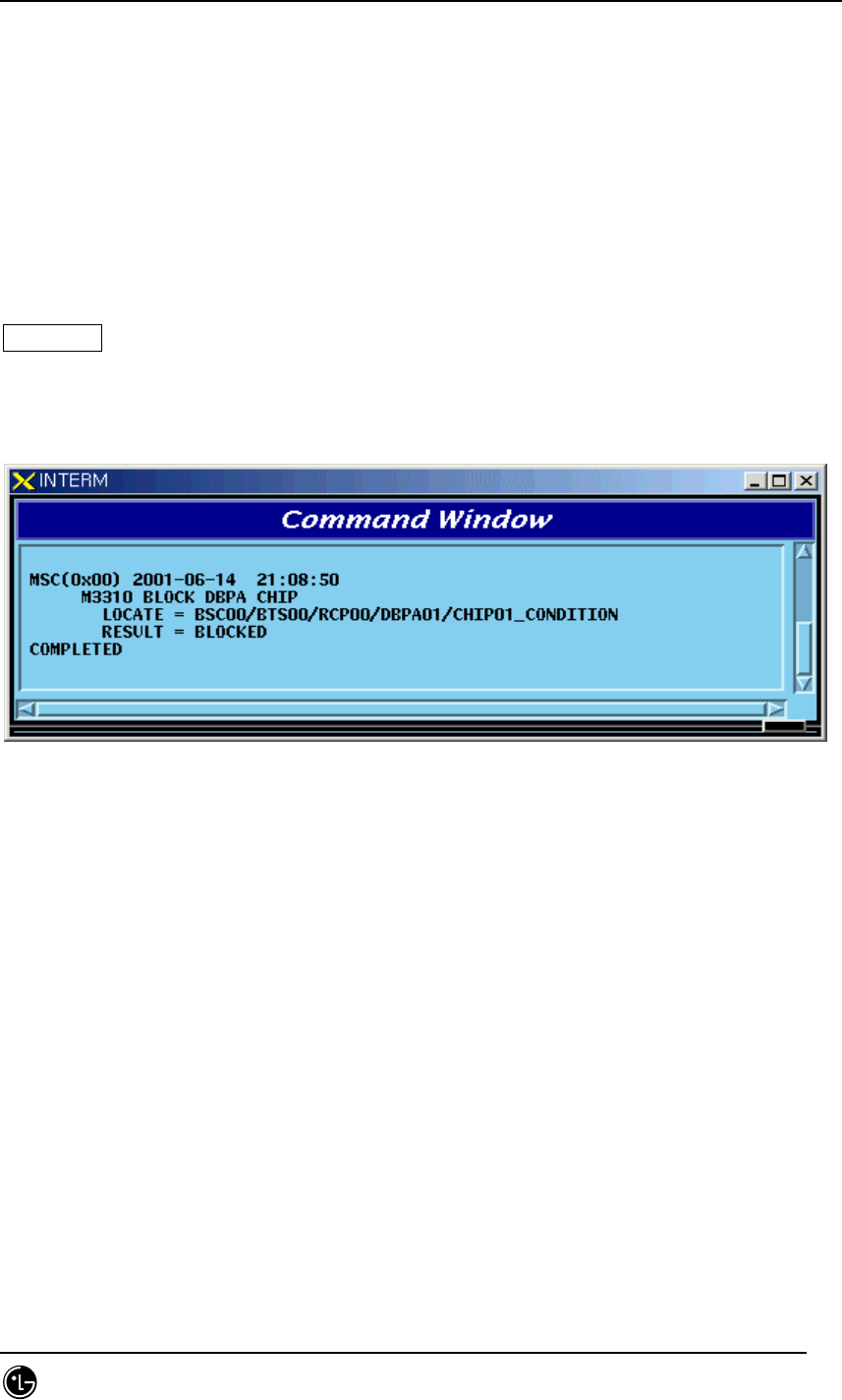
4.4.5.3. BLOCK DBPA Command
Function to block DBPA.
Command : BLK-DBPA:BSC=a,BTS=b,RCP=c,DBPA=d,[CHIP=e],[CONDITION=f];
a : BSC Number(00~11)
b : BTS Number(00~47)
c : RCP Number(0~5)
STAREX-IS BSM Manual
Page:406(877)
Issue:1.
0
SMD-011-PMA210
d : DBPA Number(0~9)
e : CHIP Number(0~1)
f : Select Option(conditional, unconditional)
Conditional : If there is call connected, wait until it is disconnected during timeout and
then block it. If it is not disconnected until timeout, do not block it.
Unconditional : block a call regardless of their presence unconditionally. (The existing
call is disconnected)
Reference : If an OverHead Channel is allocated, do not block a call unconditionally.
Input : BLK-DBPA:BSC=0,BTS=0,RCP=0,DBPA=1,CHIP=1,CONDITION=CONDITION;
Fig. 4.4-34 Result of BLOCK DBPA Command
4.4.5.4. UNBLOCK DBPA Command
Function to unblock DBPA
Command : UBLK-DBPA:BSC=a,BTS=b,RCP=c,DBPA=d,[CHIP=e],[CONDITION=f];
a : BSC Number(00~11)
b : BTS Number(00~47)
c : RCP Number(0~5)
d : DBPA Number(0~9)
e : CHIP Number(0~1)
Input : UBLK-DBPA:BSC=0,BTS=0,RCP=0,DBPA=1,CHIP=1;
STAREX-IS BSM Manual
Page:407(877)
Issue:1.
0
SMD-011-PMA210
Fig. 4.4-35 Result of UNBLOCK DBPA Command
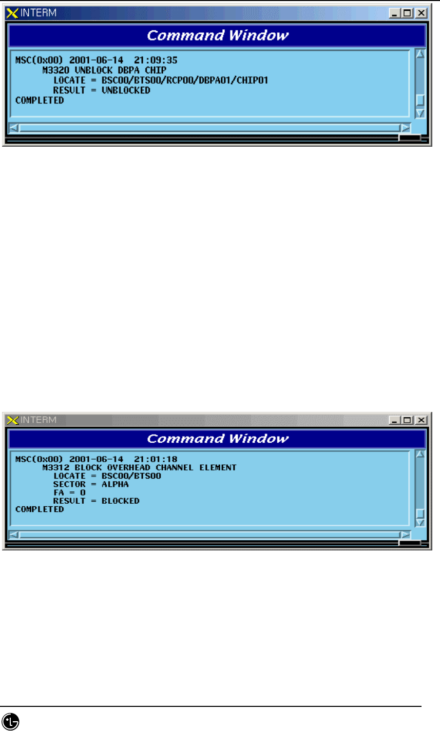
4.4.5.5. BLOCK OverHead Channel Element Display Command
Function to block OverHead Channel Element
Command : BLK-OVHD-CE:BSC=a,BTS=b,SECTOR=c,FA=d;
a : BSC Number(00~11)
b : BTS Number(00~47)
c : SECTOR(ALPHA,BETA,GAMMA,DELTA,EPSILON,ZETA)
d : FA Number(0~5)
Input : BLK-OVHD-CE:BSC=0,BTS=0,SECTOR=ALPHA,FA=0;
Fig. 4.4-36 Result of BLOCK OverHead Channel Element Display
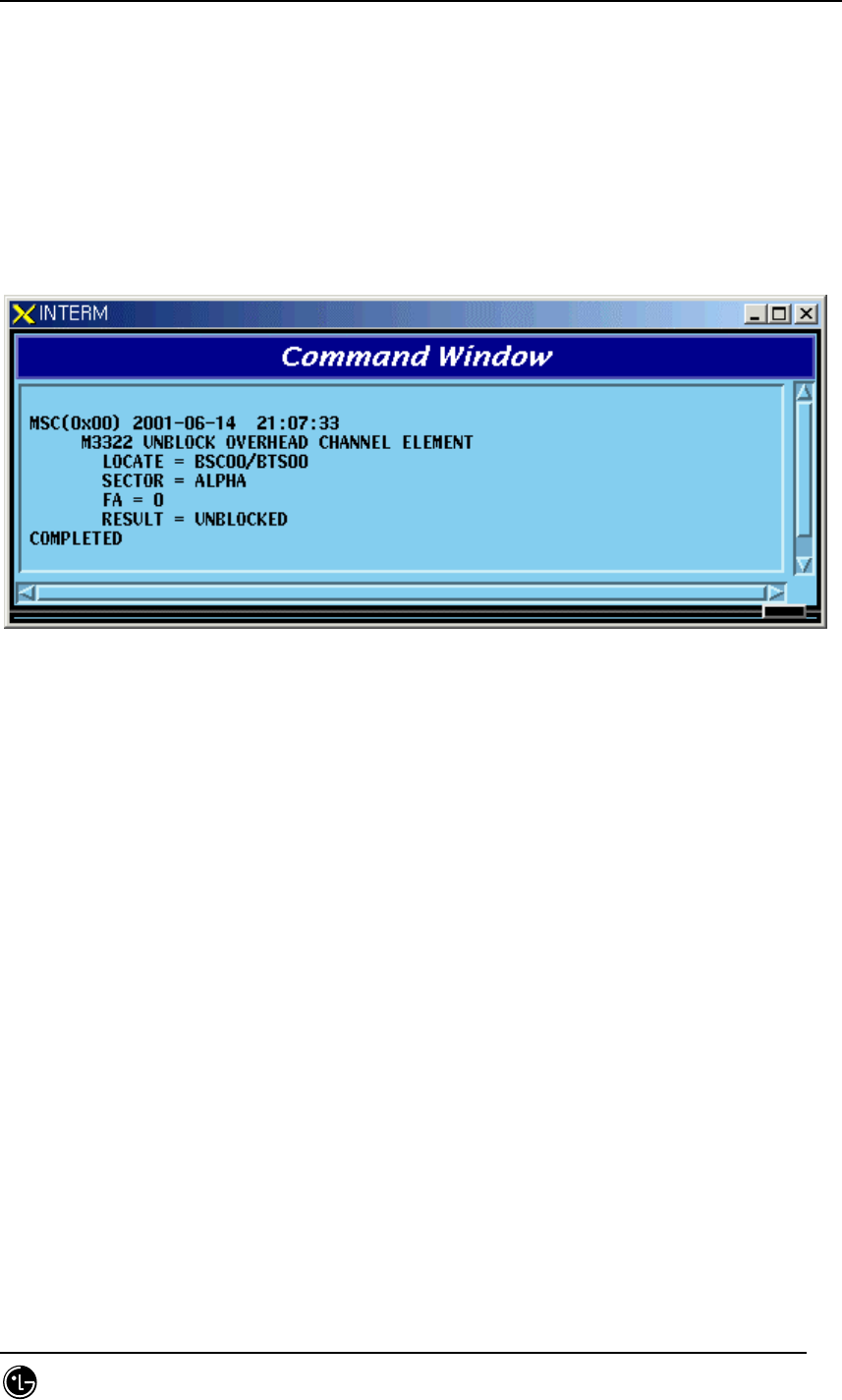
4.4.5.6. UNBLOCK OverHead Channel Element
Function to unblock OverHead Channel Element
STAREX-IS BSM Manual
Page:408(877)
Issue:1.
0
SMD-011-PMA210
Command : UBLK-OVHD-CE:BSC=a,BTS=b,SECTOR=c,FA=d;
a : BSC Number(00~11)
b : BTS Number(00~47)
c : SECTOR(ALPHA,BETA,GAMMA,DELTA,EPSILON,ZETA)
d : FA Number(0~5)
Input : UBLK-OVHD-CE:BSC=0,BTS=0,SECTOR=ALPHA,FA=0;
Fig. 4.4-37 Result of UNBLOCK OverHead Channel Element
4.4.5.7. H/W RESET BTS Device Command
Function to reset BTS Device on H/W.Level
Command : RMT-BTS-DEV:BSC=a,BTS=b,PROC=c,DEV=d,[ID=e],CLS=f;
a : BSC Number(00~11)
b : BTS Number(00~47)
c : Processor Name(BSP,BPP,CRP,RCP(00~05)
d : Device Name(ARIA,DBPA,BUDA,HPA,PACA,BADA,RISA,BOTA,LICA)
e : Device ID(0~9)
f : Class(HARDRST,ISOLAT,UNISOL)
Input : RMT-BTS-DEV:BSC=0,BTS=0,PROC=CRP,DEV=LICA,ID=0,CLS=HARDRST;
STAREX-IS BSM Manual
Page:409(877)
Issue:1.
0
SMD-011-PMA210
Fig. 4.4-38 Result of H/W RESET BTS Device Command
4.4.5.8. H/W RESET LPA Device Command
Function to reset LPA Device on H/W.Level
Command : RMT-LPA:BSC=a,BTS=b,SECTOR=c,LPA=d,CLS=e;
a : BSC Number(00~11)
b : BTS Number(00~47)
c : SECTOR(ALPHA,BETA,GAMMA,DELTA,EPSILON,ZETA)
d : LPA Number(0~5)
e : Class(HARDRST,ISOLAT,UNISOL)
Input : RMT-LPA:BSC=0,BTS=0,SECTOR=ALPHA,LPA=0,CLS=HARDRST;
Fig. 4.4-39 Result of H/W RESET LPA Device Command
STAREX-IS BSM Manual
Page:410(877)
Issue:1.
0
SMD-011-PMA210
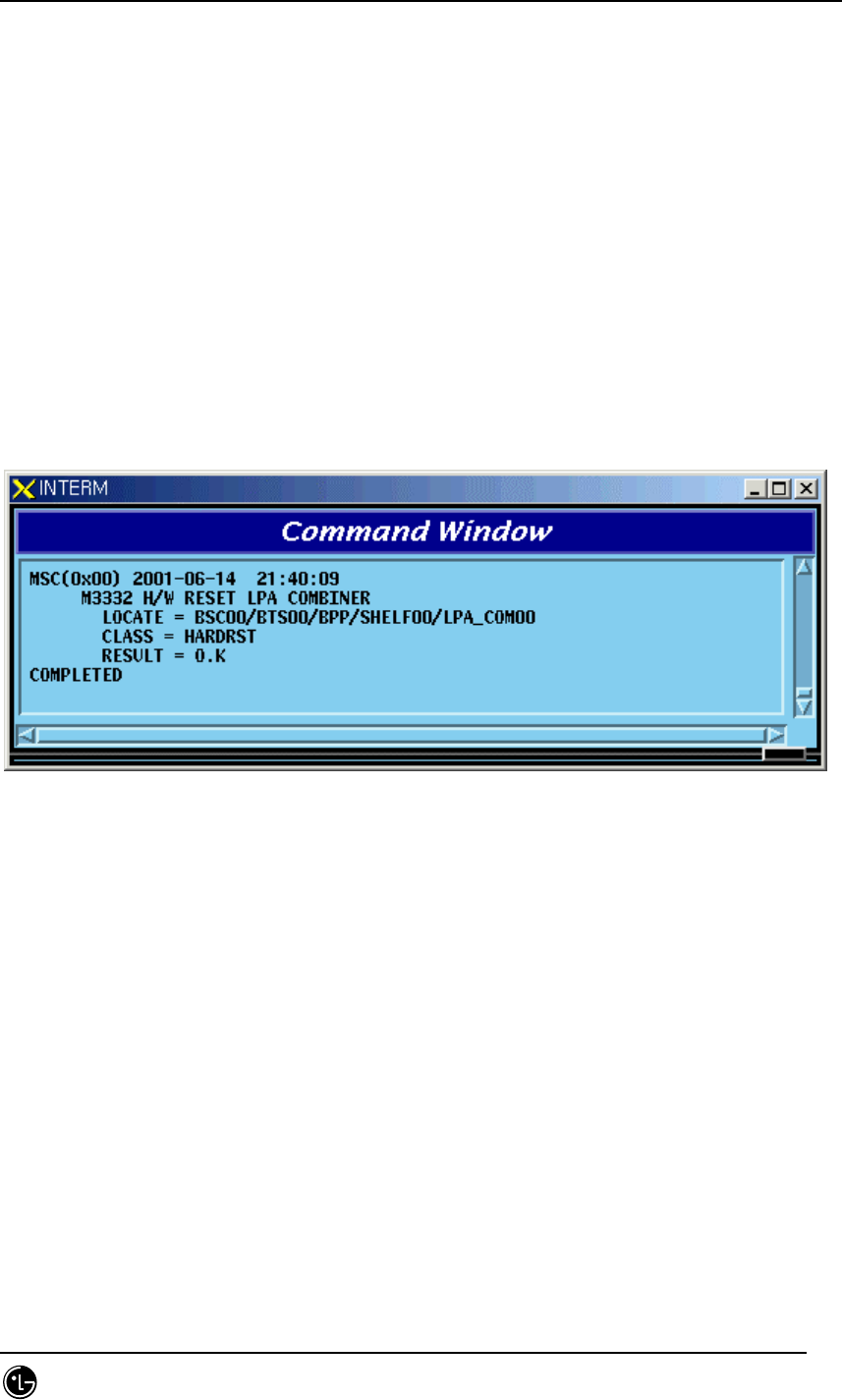
4.4.5.9. H/W RESET LPA Combiner Command
Function to reset the LPA Combiner on H/W Level
Command : RMT-LPA-COM:BSC=a,BTS=b,SHELF=c,COM=d,CLS=e;
a : BSC Number(00~11)
b : BTS Number(00~47)
c : SHELF Number(0~5)
d : Combiner Number(0~2)
e : Class(HARDRST,ISOLAT,UNISOL)
Input : RMT-LPA-COM:BSC=0,BTS=0,SHELF=0,COM=0,CLS=HARDRST;
Fig. 4.4-40 Result of LPA Combiner H/W RESET Command
4.4.5.10. BTS SHELF POWER H/W RESET Command
Function to reset BTS SHELF POWER on H/W Level
Command : RMT-BTS-SHF:BSC=a,BTS=b,SHF=c,CLS=d;
a : BSC Number(00~11)
b : BTS Number(00~47)
c : SHELF Name(BANU,RCBU(00~05)
d : Class(HARDRST,ISOLAT,UNISOL)
Input : RMT-BTS-SHF:BSC=0,BTS=0,SHF=RCBU00,CLS=HARDRST;
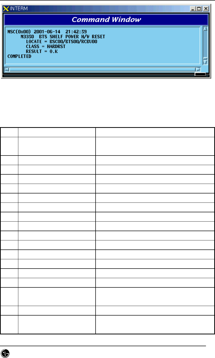
STAREX-IS BSM Manual
Page:411(877)
Issue:1.
0
SMD-011-PMA210
Fig. 4.4-41 Result of BTS SHELF POWER H/W RESET Command
4.4.6. Status Message Control
Table 4.4-5 Status Message LIST
Codes Definition Description
S3002 CAN CNP/PNP Status Change
Display
When Processor Status changes, it occurs.
S3003 AMP Status Change Display When Processor Status changes, it occurs.
S3004 ALP Status Change Display When Processor Status changes, it occurs.
S3005 CCP Status Change Display When Processor Status changes, it occurs.
S3006 SMP Status Change Display When Processor Status changes, it occurs.
S3007 VMP Status Change Display When Processor Status changes, it occurs.
S3008 PCP Status Change Display When Processor Status changes, it occurs.
S3009 BSC-NCP Status Change Display When Processor Status changes, it occurs.
S3010 BSP Status Change Display When Processor Status changes, it occurs.
S3011 SCP Status Change Display When Processor Status changes, it occurs.
S3012 BPP Status Change Display When Processor Status changes, it occurs.
S3013 RCP Status Change Display When Processor Status changes, it occurs.
S3017 CRP Status Change Display When Processor Status changes, it occurs.
S3020 PMP Status Change Display When Processor Status changes, it occurs.
S3201 CNP ASIA Status Change Display Displayed upon device status change
S3202 CNP ASCA Status Change
Display
Displayed upon device status change
S3205 PNP ASIA Status Change Display Displayed upon device status change
S3206 PNP ASCA Status Change
Display
Displayed upon device status change

STAREX-IS BSM Manual
Page:412(877)
Issue:1.
0
SMD-011-PMA210
S3209 PCP BCRA Status Change
Display
Displayed upon device status change
S3210 PMP BCRA Status Change
Display
Displayed upon device status change
S3211 AMP GPSR Status Change
Display
Displayed upon device status change
S3220 NCP ASIA Status Change Display Displayed upon device status change
S3221 NCP ASCA Status Change
Display
Displayed upon device status change
S3222 NCP ATSA Status Change
Display
Displayed upon device status change
S3224 ALP ALMA Status Change
Display
Displayed upon device status change
S3230 BSP GPS Status Change Display Displayed upon device status change
S3501 CCP Overload State Change
Display
Displayed when overload status is generated,
released and changed owing to load change in
CCP
S3502 BSP Overload State Change
Display
Displayed when overload status is generated,
released and changed owing to load change in
BSP
STAREX-IS BSM Manual
Page:413(877)
Issue:1.
0
SMD-011-PMA210
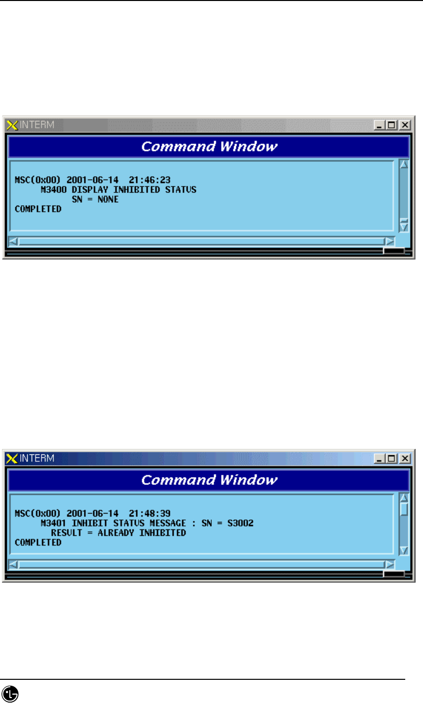
4.4.6.1. Inhibited Status Message Display Command
Function to display Status Message whose display to Outterm is inhibited
Command : DIS-INH-STS;
Input : DIS-INH-STS;
Fig. 4.4-42 Result Inhibited Status Message Display Command
4.4.6.2. Status Message Display Inhibition Command
Function to inhibit Status Message display
Command : INH-STS-MSG:SN=a;
a: SN Number(ALL,S3002~S3020,S3201~S3230, S3501,S3502)
Input : INH-STS-MSG:SN=S3002;
Fig. 4.4-43 Result of Status Message Display Inhibition Command
STAREX-IS BSM Manual
Page:414(877)
Issue:1.
0
SMD-011-PMA210
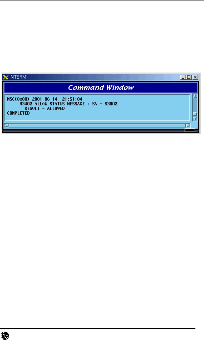
4.4.6.3. Allow Inhibited Message Command
Function to allow display of Status Message whose display to Outterm is inhibited
Command : ALW-STS-MSG:SN=a;
a: SN Number(ALL,S3002~S3020, S3201~S3230, S3501,S3502)
Input : ALW-STS-MSG:SN=S3002;
Fig. 4.4-44 Result of Inhibited Message Display Allow Command
4.4.7. Overload Status Control
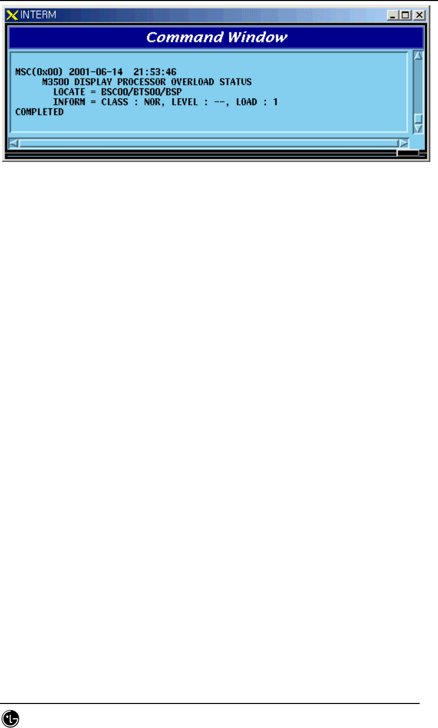
4.4.7.1. Processor Overload Status Display Command
Function to display processor Overload Status
Command : DIS-OVLD-STS:[BSC=a],[BTS=b],PROC=c;
a : BSC Number(00~11)
b : BTS Number(00~47)
c : Processor Name(CCP,BSP)
Input : DIS-OVLD-STS:BSC=0,BTS=0,PROC=BSP;
STAREX-IS BSM Manual
Page:415(877)
Issue:1.
0
SMD-011-PMA210
Fig. 4.4-45 Result of Processor Overload Status Display Command
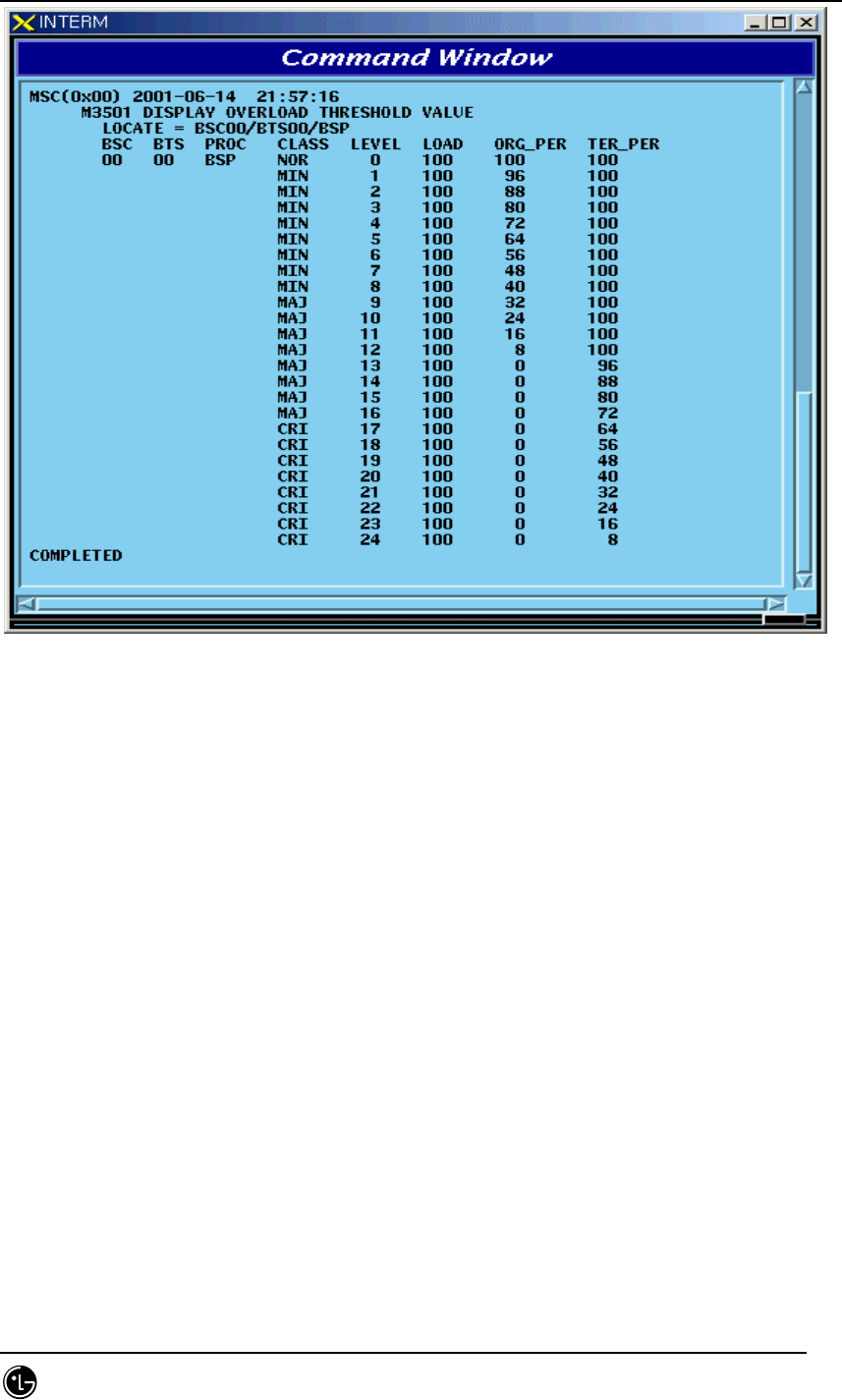
4.4.7.2. Overload Threshold Value Display Command
Function to display Overload Threshold Value
Command : DIS-OVLD-THR:BSC=a,[BTS=b],PROC=c;
a : BSC Number(00~11)
b : BTS Number(00~47)
c : Processor Name(CCP,BSP)
Input : DIS-OVLD-THR:BSC=0,BTS=0,PROC=BSP;
STAREX-IS BSM Manual
Page:416(877)
Issue:1.
0
SMD-011-PMA210
Fig. 4.4-46 Result of Overload Threshold Value Display Command
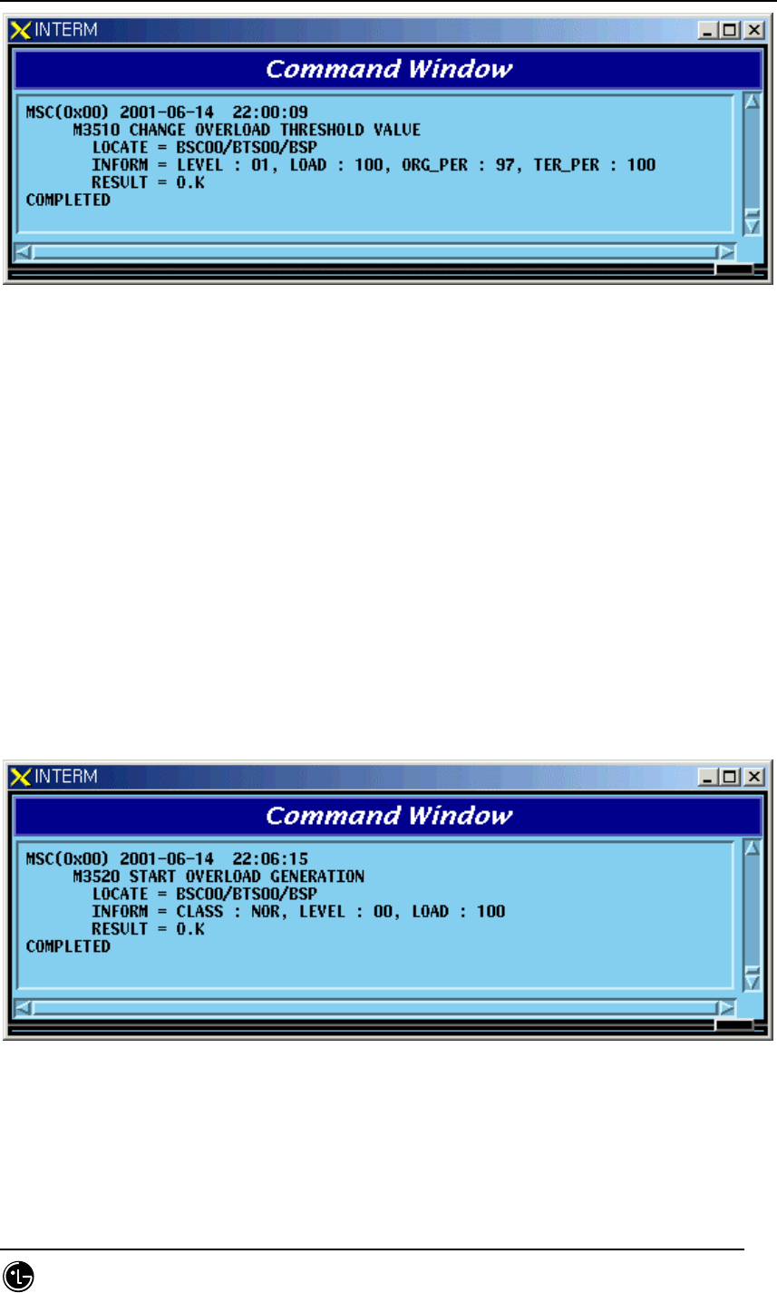
4.4.7.3. Overload Threshold Value Change Command
Function to change Overload Threshold Value.
Command:
CHG-OVLD-THR:BSC:a,[BTS=b],LEVEL=c,[LOAD=d], [ORG_PER=e],[TER_PER=f];
a : BSC Number(00~11)
b : BTS Number(00~47)
c : LEVEL(0~100)
d : LOAD(0~100)
e : ORG_PER(0~100)
f : TER_PER(0~100)
Input :
CHG-OVLD-THR:BSC:0,BTS=0,LEVEL=0,LOAD=100, ORG_PER=97,TER_PER=100;
STAREX-IS BSM Manual
Page:417(877)
Issue:1.
0
SMD-011-PMA210
Fig. 4.4-47 Result of Overload Threshold Value Change Command
4.4.7.4. Overload Generation Test Command
Function to generate Overload threshold value
Command : STRT-OVLD-GEN:BSC=a,[BTS=b],PROC=c,LEVEL=d;
a : BSC Number(00~11)
b : BTS Number(00~47)
c: Processor Name(CCP,BSP)
d: LEVEL(0~24)
Input : STRT-OVLD-GEN:BSC=0,BTS=0,PROC=BSP,LEVEL=0;
Fig. 4.4-48 Result of Overload Generation Test Command
4.4.7.5. Overload Generation Test STOP Command
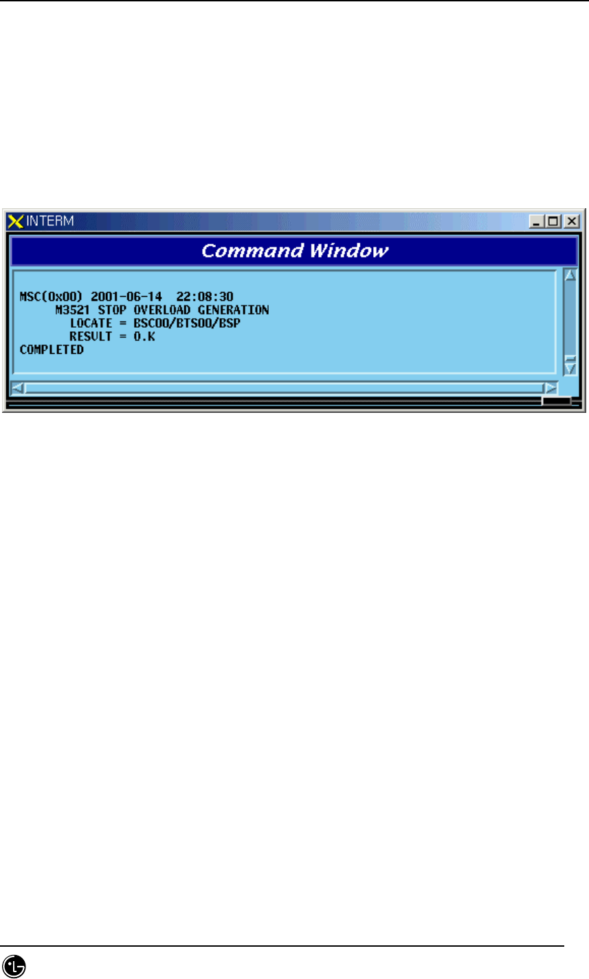
STAREX-IS BSM Manual
Page:418(877)
Issue:1.
0
SMD-011-PMA210
Function to stop the Overload Generation Test
Command : STOP-OVLD-GEN:BSC=a,[BTS=b],PROC=c,LEVEL=d;
a : BSC Number(00~11)
b : BTS Number(00~47)
c: Processor Name(CCP,BSP)
d: LEVEL(0~24)
Input : STOP-OVLD-GEN:BSC=0,BTS=0,PROC=BSP,LEVEL=0;
Fig. 4.4-49 Result of Overload Generation Test STOP Command
4.4.7.6. Command to Display Whether or not the Overload Generation
Test is performed
Function to find out whether the Overload Display Test is performed
Command : DIS-OVLD-GEN:BSC=a,[BTS=b],PROC=c,LEVEL=d;
a : BSC Number(00~11)
b : BTS Number(00~47)
c: Processor Name(CCP,BSP)
d: LEVEL(0~24)
Input : DIS-OVLD-GEN:BSC=0,BTS=0,PROC=BSP,LEVEL=0;
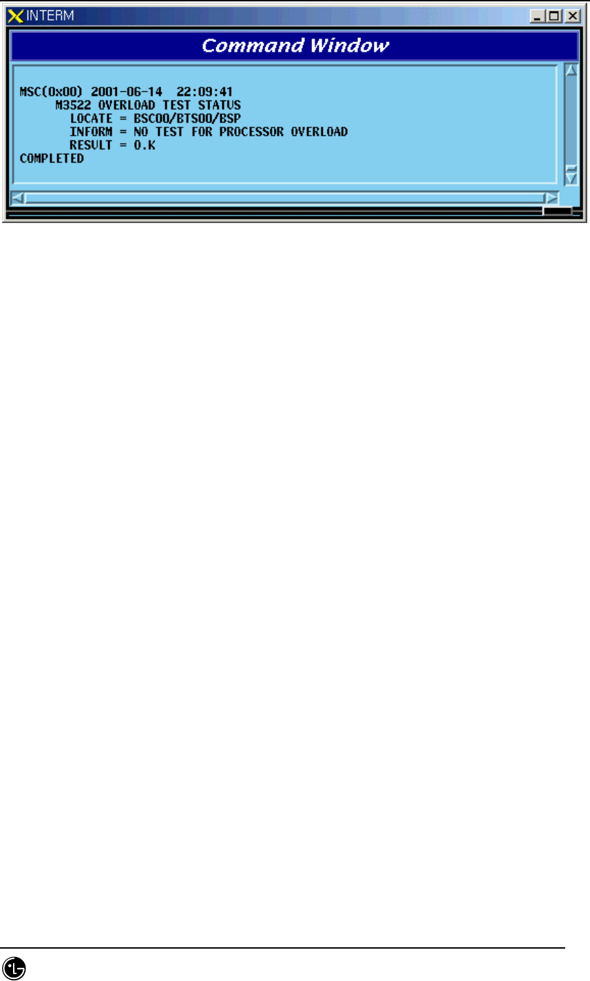
STAREX-IS BSM Manual
Page:419(877)
Issue:1.
0
SMD-011-PMA210
Fig. 4.4-50 Command to Determine Whether to Perform the Overload Generation Test

STAREX-IS BSM Manual
Page:420(877)
Issue:1.
0
SMD-011-PMA210
4.5. Test Command
4.5.1. On-Line Test-related Command
On-Line Test is a function that allows a test to be performed automatically at a
specific time on a specific day and includes the following: Vocoder, CE, BTS Markov
test and VSWR test. The tests of CE, BTS Markov and VSWR find out presence of
faults in hardware of Channel Elements in BTS and the test function for radio
environment, and the Vocoder test finds out presence of faults in hardware of
Vocoder in BSC. Because the tests of CE, Vocoder, BTS Markov, and VSWR seize call
resources, the user designates the specific time (idlest time) during the time that only
a test is allowed. The tests of CE, BTS Markov, and VSWR are conducted under the
supervision of BSP while the Vocoder test is conducted under the supervision of CCP.
If the user designates the day and start/ending time for the Online test, and the ID
scope of the board to be tested, BSM becomes the designated time of the designated
day and if the test is in the ALLOW status, it commands the corresponding Processor
to start/end the test.
The performance of the On-Line test is decided by Command INH-ONL-TEST (Inhibit
Test), ALW-ONL-TEST(Allow Test). Only when the status is designated as “ALLOW”
by ALW-ONL-TEST Command, On-Line test is performed. The Command of INH-
ONL-TEST inhibits the test. Besides these two Commands, there is a command to stop
the test by each Test(CE : STS-CE-ONL, Vocoder : STS-VCE-ONL, BTS Markov :
STS-MKV-ONL, VSWR : STS-VSWR-ONL). If the test was stopped by INHIBIT
Command, the On-Line Test is not performed even if the designated time of the
designated day of the week arrives because inhibit/allow status is changed to
“INHIBIT”. ,. However, if the Test was stopped by the above listed STOP Command,
the On-Line Test that was performed on that day only comes to a halt and at the
designated time of the next designated day of the week the On-Line Test is to be
performed normally because DB Flag that indicates the status of INHIBIT/ALLOW is
not changed
.
4.5.1.1. On-Line Test Inhibit Command
It is the function that inhibits On Line Test for CE, Vocoder, BTS Markov, and VSWR
test. In the cases of CE, BTS Markov, and VSWR test, input the corresponding BTS
number and in the case of Vocoder test, input the corresponding BSC number.
• Command INH-ONL-TEST:EXE=a, BSC=b,[BTS=c];
a: VCE/CE/MKV/VSWR
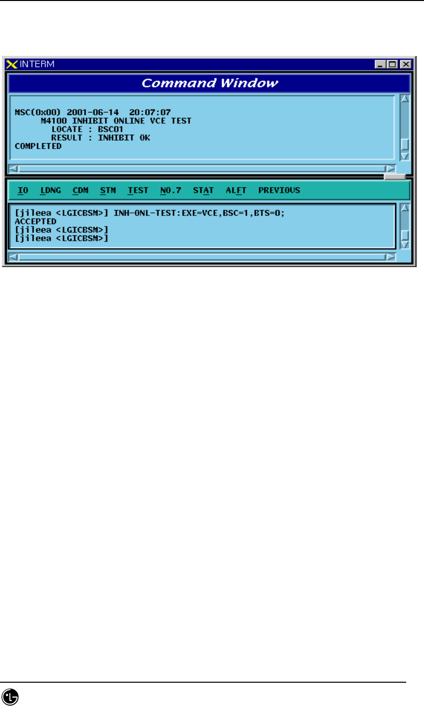
STAREX-IS BSM Manual
Page:421(877)
Issue:1.
0
SMD-011-PMA210
b: BSC number (0~11)
c: BTS number (0~47)
• Input/Output
Fig. 4.5-1 Result of Test Inhibit Command Execution
4.5.1.2. On-Line Test Allow Command
Function that allows Online Test for CE, Vocoder, BTS Markov, and VSWR test
For CE, BTS Markov and VSWR test, input the corresponding BTS number and for
Vocoder test, input corresponding BSC number.
• Command ALW-ONL-TEST:EXE=a,BSC=b[BTS=c];
a: VCE/CE/MKV/VSWR
b: BSC number (0~11)
c: BTS number (0~47)
• Input/Output
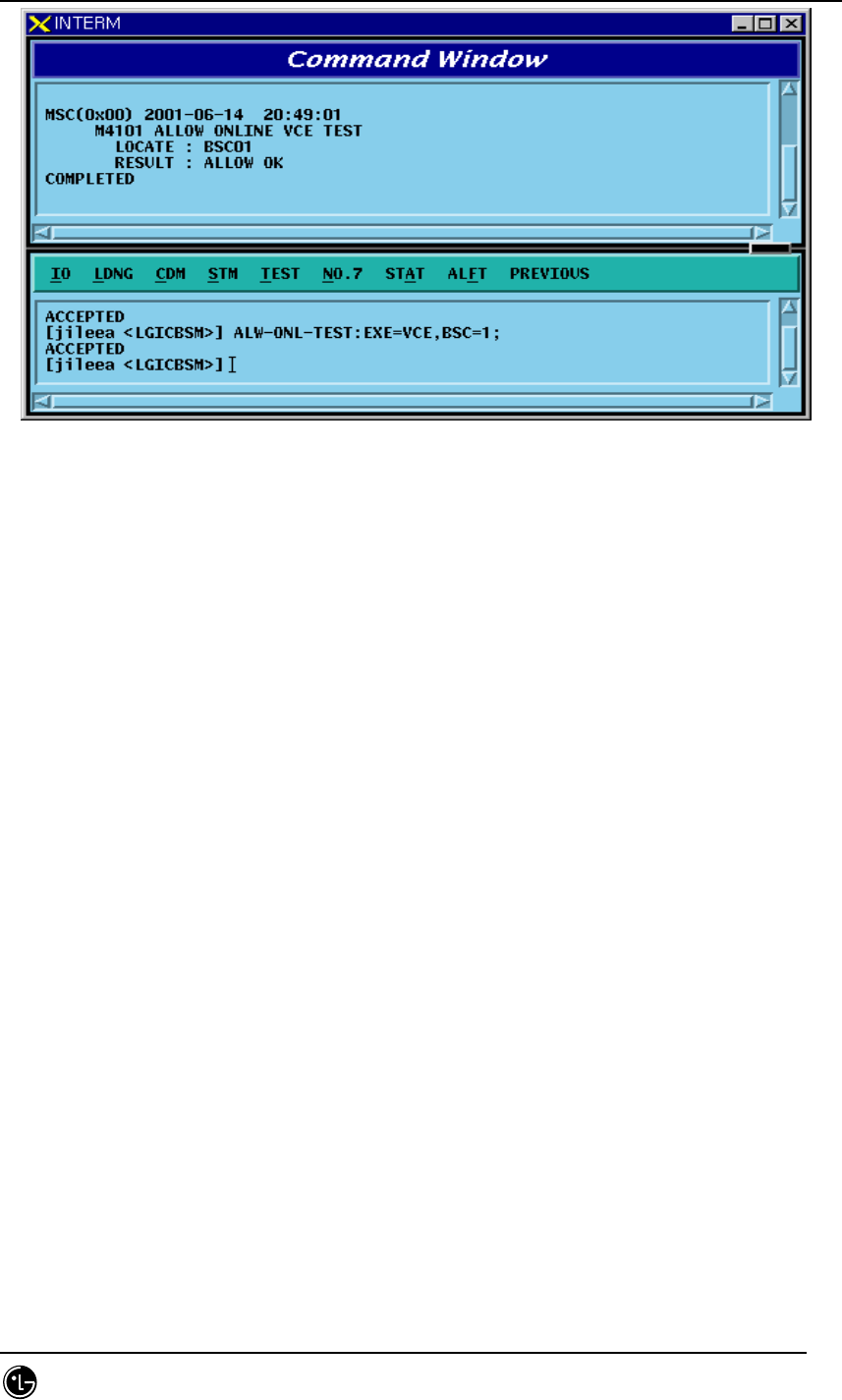
STAREX-IS BSM Manual
Page:422(877)
Issue:1.
0
SMD-011-PMA210
Fig. 4.5-2 Result of Test Allow Command Execution
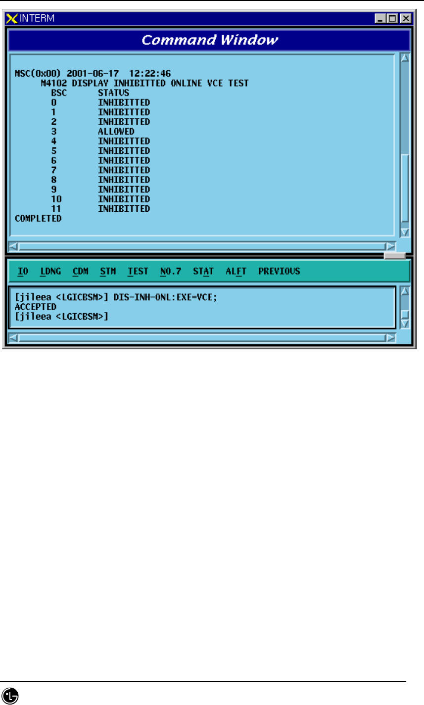
4.5.1.3. On-Line Test Inhibit Item Display Function
Function to display the inhibit of the on line test for the specific tests among the on-
line tests by BSC and BTS. For Vocoder test, it displays Inhibit status. In case of CE,
BTS Markov and in case of the VSWR test, it displays the status by BTS.
• Command DIS-INH-ONL:EXE=a,BSC=b[BTS=c];
a: VCE/CE/MKV/VSWR
b: BSC number (0~11)
c: BTS number (0~47)
• Input/Output
STAREX-IS BSM Manual
Page:423(877)
Issue:1.
0
SMD-011-PMA210
Fig. 4.5-3 Result of Test Inhibit/Allow List Display Command Execution

STAREX-IS BSM Manual
Page:424(877)
Issue:1.
0
SMD-011-PMA210
4.5.2. Test-related to Channel Element
Channel Element Test is performed in BIT(Built In Test) for each chip. The types of
BIT Test are as follows:
- Bus Interrupt Test
- ChipX16 Test
- PP2S Test
- PCG Test
This BIT Test is normally performed on Chip with OVHD channel and Chip seized with
a call and the result is reported to BSM.
Table 4.5-1CE Test Result Message
On-Demand DESCRIPTION
BIT_OK
BIT_BUS_FAIL
BIT_INT_FAIL
BIT_CHIPX16_FAIL BIT_PP2S_FAIL
BIT_PCG_FAIL
BIT_RAM_FAIL
BIT_PROGRESS_FAIL
NORMAL
BUS INTERFACE TEST FAIL
INTERNAL INTERRUPT TEST FAIL
CHIPX16 TEST FAIL
PCG TEST FAIL
MEMORY TEST FAIL
TEST PERFORMING FAIL
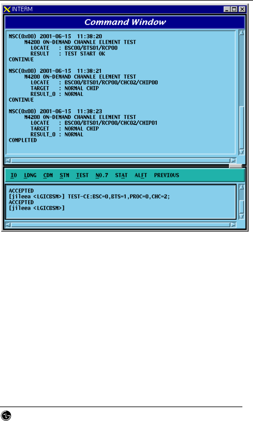
4.5.2.1. Channel Element Test Function
Function to perform BIT test by CHC and CHIP unit.
• Command TEST-CE :BSC=a ,BTS=b ,PROC=c [,CHC=d] [,CHIP=e];
a: BSC number (0~11)
b: BTS number (0~47)
c: RCP number (0~9)
d: Channel Card Number (0~9)
e: Chip Number (0~1)
• Input/Output
STAREX-IS BSM Manual
Page:425(877)
Issue:1.
0
SMD-011-PMA210
Fig. 4.5-4 Result of CE BIT Test Execution

STAREX-IS BSM Manual
Page:426(877)
Issue:1.
0
SMD-011-PMA210
4.5.3. Vocoder Test Function
The types of Vocoder Tests are as follows:
o DSP H/W Test
- Determines the presence of problems in ROM, RAM, ALU of DSP in
Vocoder
- Diagnosis the presence of problems by checking Checksum, Read/Write,
Flag Set, etc.
- Caused by defective DSP Chip
o Timing Module Test (Channel Test)
- VCP generates Vocoder and Tx.Rx Timing by using MFP(Multiple-
Function Processor) in order to exchange voice data with SLP every
20ms.
- It judges the presence of problems in Vocoder counter by checking the
generated Rx.Tx timing.
o Loopback Test (Channel Test)
- It is a test to decide whether or not the status of Loop used in Qcelp
Algorithm test is normal and its Loop section has VLIA, VCMA and VCPA.
All of them should be normal to execute the Qcelp Algorithm test. VCP
generates Test Pattern and by checking the Loopbacked result, it decides
an absence of failure.
o QCELP Algorithm Test (Channel Test)
- Due to intermittent problems in Vocoder and VCPA Card H/W, a
phenomenon that a call is not heard bi-directionally occurs. In order to
prevent this from happening, Qcelp Algorithm is tested. This test
determines whether Vocoder is normal by testing whether status
transition of Qcelp Algorithm is normally performed by the state. .
Table 4.5-2 Vocoder Test Result
On-Demand / On-Line Message Description

STAREX-IS BSM Manual
Page:427(877)
Issue:1.
0
SMD-011-PMA210
FLT_DSP_HW
FLT_CLK
FLT_VCPA_LOOPBACK
FLT_VCMA_LOOPBACK
FLT_VLIA_LOOPBACK
FLT_QCELP_ST0
FLT_QCELP_ST1
FLT_QCELP_ST2
FLT_QCELP_ST3
DSP HW test Fault
Timing Module test Fault
Vocoder Processor Loopback test Fault
Vocoder Master board Loopback test Fault
Vocoder Line interface Loopback test Fault
Qcelp Algorithm test Fault state0
Qcelp Algorithm test Fault state1
Qcelp Algorithm test Fault state2
Qcelp Algorithm test Fault state3
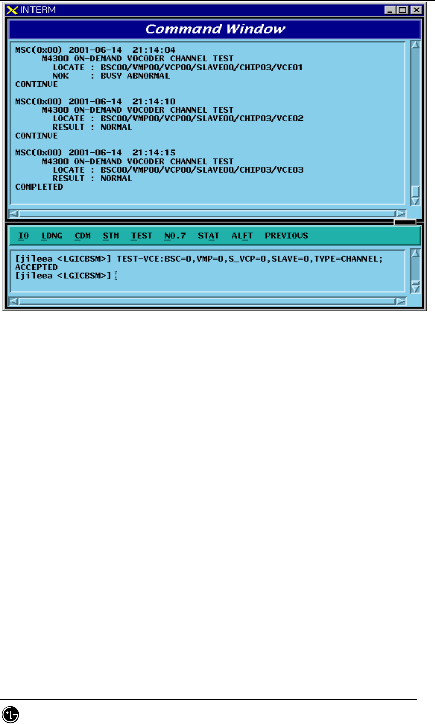
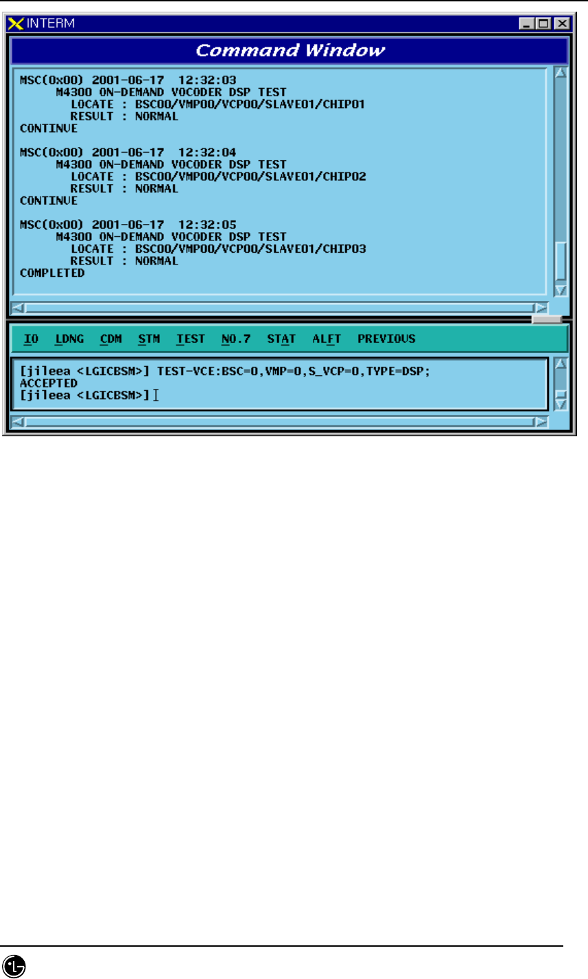
4.5.3.1. On-Demand Vocoder Test Function
Function to test Vocoder DSP or Channel by VCP/SLAVE/CHIP unit.
• Command TEST-VCE: BSC=a ,VMP=b ,S_VCP=c [,E_VCP=d] [,SLAVE=e] [,CHIP=f]
[,VCE=g] ,TYPE=h [,OPTION=i] [,WAIT_T=j]
a: BSC number (0~11)
b: VMP number (0~7)
c, d: VCP number (0~15)
e: SLAVE number (0~1)
f : CHIP number (0 ~ 3)
h: Test Type(DSP, Channel)
i: Test Option(SKIP, RELEASE, WAIT_THEN) => These are options
used to test channels when a call is seized, and SKIP does not perform a test
when a call is seized but skips. With option RELEASE, it disconnects a call
when a call is seized and then performs a test. With option WAIT_THEN, it
waits as long as j time is allowed and if a call is released within the designated
time, then it goes on with a test. However, if a call is not released, it skips.
J: Wait Time(5~300 sec)
• Input/Output
STAREX-IS BSM Manual
Page:428(877)
Issue:1.
0
SMD-011-PMA210
Fig. 4.5-5 Result of On-Demand Vocoder Test(Channel Type) Execution
STAREX-IS BSM Manual
Page:429(877)
Issue:1.
0
SMD-011-PMA210
Fig. 4.5-6 Result of On-Demand Vocoder Test(DSP Type) Execution
4.5.3.2. Parameter Change Command Related to On-Line Vocoder Test
Function to change On-Line Vocoder test start/ending time, test day and the scope of
VMP/VCP to be tested.
• Command CHG-VCE-PARA :BSC=a ,S_VMP=b [,E_VMP=c] ,S_VCP=d [,E_VCP=e]
[,STI ME=f] [,ETIME=g] ,WDAY=h;
a: BSC number (0~11)
b,c: VMP number(0~7)
d,e: VCP number(0~15)
f: On-Line test Start Time (0~23 Hour)
g: On-Line test End Time (1~24 Hour)
h: Test Day(Month ~ Day, Daily)
• Input/Output
STAREX-IS BSM Manual
Page:430(877)
Issue:1.
0
SMD-011-PMA210
Fig. 4.5-7 Result of On-Line Vocoder Test parameter Change Command Execution
Fig. 4.5-8 Result of On-Line Test at the time of On-Line Vocoder Test Execution
STAREX-IS BSM Manual
Page:431(877)
Issue:1.
0
SMD-011-PMA210
Parameter Change
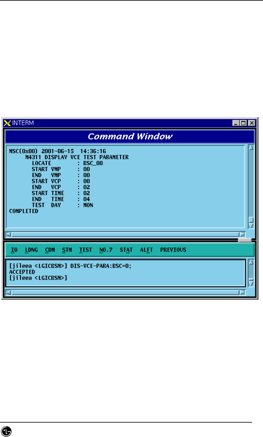
4.5.3.3. Parameter Display Command related to On-Line Vocoder Test
Function to display On-Line Vocoder test start/ending time, test day, and the scope of
VMP/VCPto be tested.
• Command DIS-VCE-PARA:BSC=a;
a: BSC number (0~11)
• Input/Output
Fig. 4.5-9 Result of On-Line Vocoder Test Parameter Display Command Execution
4.5.3.4. Display Command of On-Line Vocoder Test Result
Function to display the On-Line Vocoder Test Results which are stored in CCP to BSM
by the VMP unit
• Command DIS-VCE-RSLT:BSC=a,VMP=b;
a: BSC number (0~11)
b: VMP number (0~7)
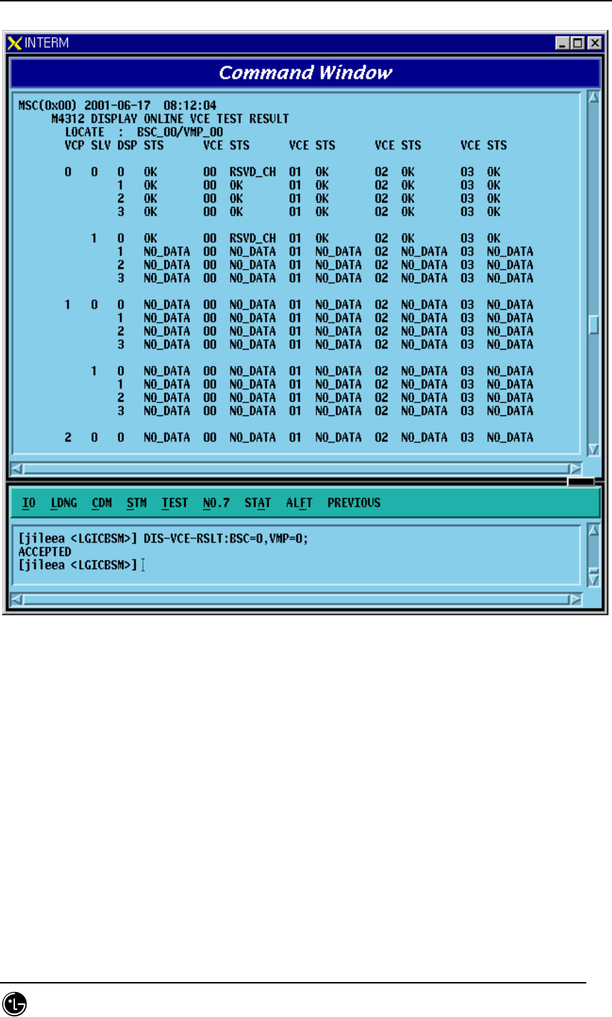
STAREX-IS BSM Manual
Page:432(877)
Issue:1.
0
SMD-011-PMA210
• Input/Output
Fig. 4.5-10 On-Line Vocoder Test Result Display Command
4.5.3.5. Display Command of On-Line Vocoder Test Status
Function to display the On-Line Vocoder Test performance status and to stop the test.
If Item Field is designated as “DISPLAY”, it displays On-Line Vocoder test status of
the present corresponding BSC, and if it is designated as "END_ONL", it stops current
On-Line test.
• Command STS-VCE-ONL:BSC=a,ITEM=b;
a: BSC number (0~11)
b: Execution ITEM (DISPLAY/END-ONL)
• Input/Output
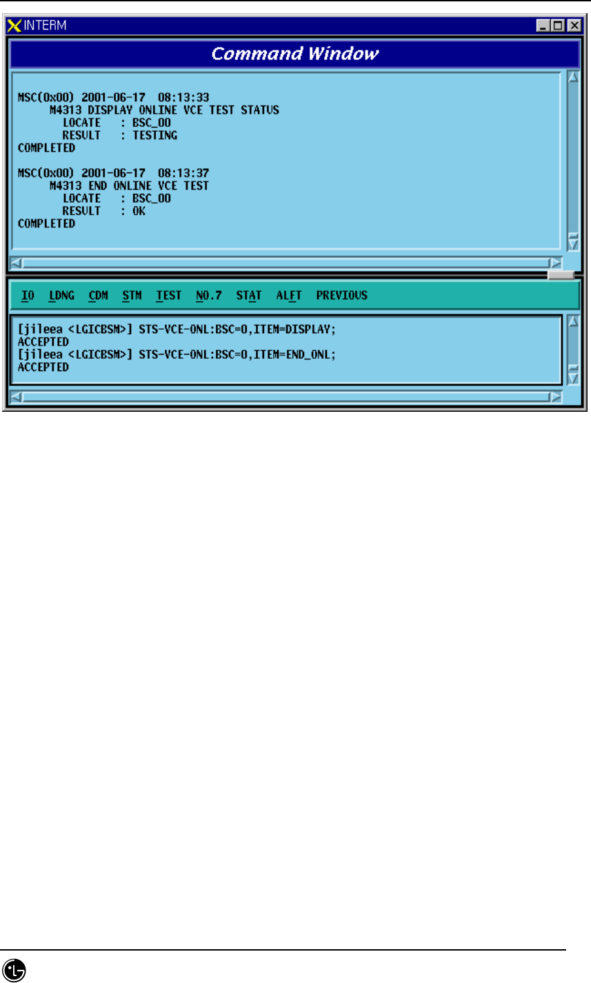
STAREX-IS BSM Manual
Page:433(877)
Issue:1.
0
SMD-011-PMA210
Fig. 4.5-11 On-Line Vocoder Test End Command, Status Display Command Execution Result

STAREX-IS BSM Manual
Page:434(877)
Issue:1.
0
SMD-011-PMA210
4.5.4. Link Test Function
Link test is divided into PING test, IPC test, ATM Path test, and Trunk BER test. PING
test checks the Link status of Application Level by using Ping command from Master
Processor to each Target Processor. IPC test checks the presence of problems in
LINK by conducting IPC Test to the mounted processors/devices. ATM Path test
checks presence of faults in ATM LINK Level by conducting ATM Layer Test on the
mounted Processor/Devices. Trunk BER test sends/receives the designated number of
ATM Cells to the operator designated BTS Link to get Error Rate.
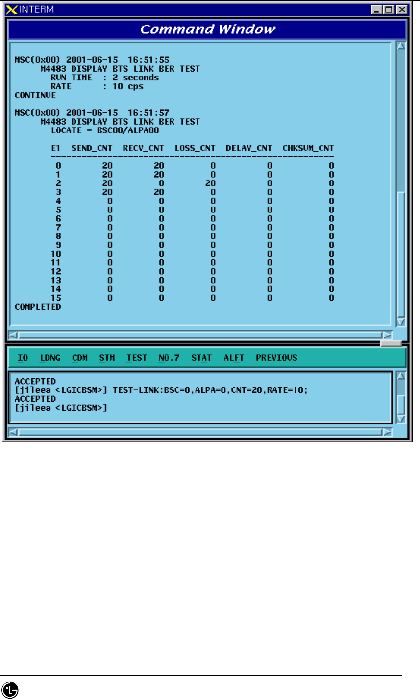
4.5.4.1. Trunk BER Test Function
Function to check the presence of problems in Trunk(16 E1) Link between BTS and
BSC. Trunk BER Test analyzes performance per Link of each ALPA and LICA and the
analyzed result is displayed in a certain format to BMS. One link is selected and while
exchanging as many as the designated number of ATM Cells, test is conducted and
Data Error Rate is displayed.
• Command TEST-LINK :BSC=a ,ALPA=b [,CNT=c] [,RATE=d];
a: BSC number (0~11)
b: ALPA number(0~9)
c: Send Cell Count(1 ~ 1,000,000)
d: Data Rate(1 ~ 90: Number of Cells transferred per a second)
• Input/Output
STAREX-IS BSM Manual
Page:435(877)
Issue:1.
0
SMD-011-PMA210
Fig. 4.5-12 Result of Trunk BER Test Performance
4.5.4.2. PING Test Function
Function to check Link Status for the Target Processor by the Master Processor that
was input to MMI of BSM by using the Ping command
Ping test is divided into Point To Point Test and Point To Multi Test.
• Command TEST-PING:SRC=a,DST=b[,BSC=c][,BTS=d][,SMP=e][,VMP=f][,PCF=g];
a: Source Processor
b: Destination Processor(If there is input, it is PTP, if not, it is PTM)
c: BSC number(0~11)
d: BTS number(0~47)
STAREX-IS BSM Manual
Page:436(877)
Issue:1.
0
SMD-011-PMA210
e: SMP number(0~5)
f: VMP number(0~7)
g: PCF number(0~2)
• Input/Output
Fig. 4.5-13 Result of PING Test Performance
4.5.4.3. IPC Test Function
Function to check the presence of problems in the Link status between
Processor/Device by executing IPC command of Application Level .
IPC Test is divided into PTP test and PTM test.
• Command TEST-IPC :SRC=a [,DST=b] [,BSC=c] [,BTS=d] [,SMP=e] [,VMP=f]
[,PCF=g];
a: Source Processor
b: Destination Processor(If input does exist, it is PTP and if not, it is PTM)
c: BSC number(0~11)
d: BTS number(0~47)
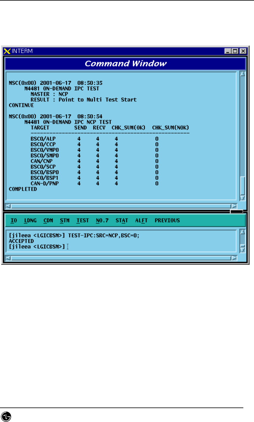
STAREX-IS BSM Manual
Page:437(877)
Issue:1.
0
SMD-011-PMA210
e: SMP number(0~5)
f: VMP number(0~7)
g: PCF number(0~2)
• Input/Output
Fig. 4.5-14 Result of IPC Test Performance
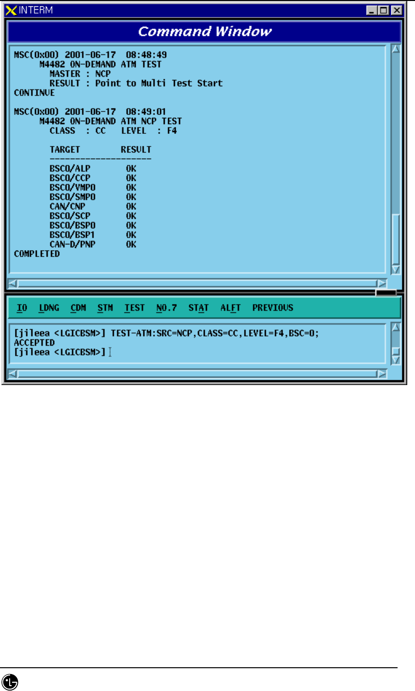
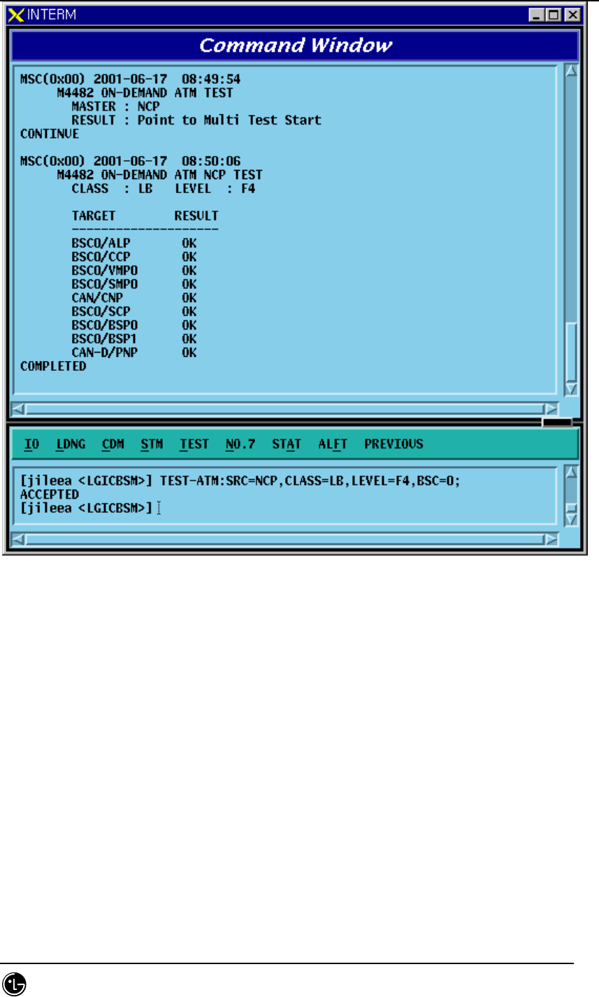
4.5.4.4. ATM Path Test Function
Function to check presence of problems in Link Status between Processor and Device
by executing ATM CC, LB, PM command.
It is divided into PTP Test and PTM Test.
• Command TEST-
TM:SRC=a[,DST=b],CLASS=c,LEVEL=d[,BSC=e][,BTS=f][,SMP=g] [,VMP=h] [,PCF=i];
a: Source Processor
b: Destination Processor(If input does exist, it is PTP, and if not, it is PTM)
c: Test class(CC: Continuity Check, LB: Loop Back, PM: Execution Monitor)
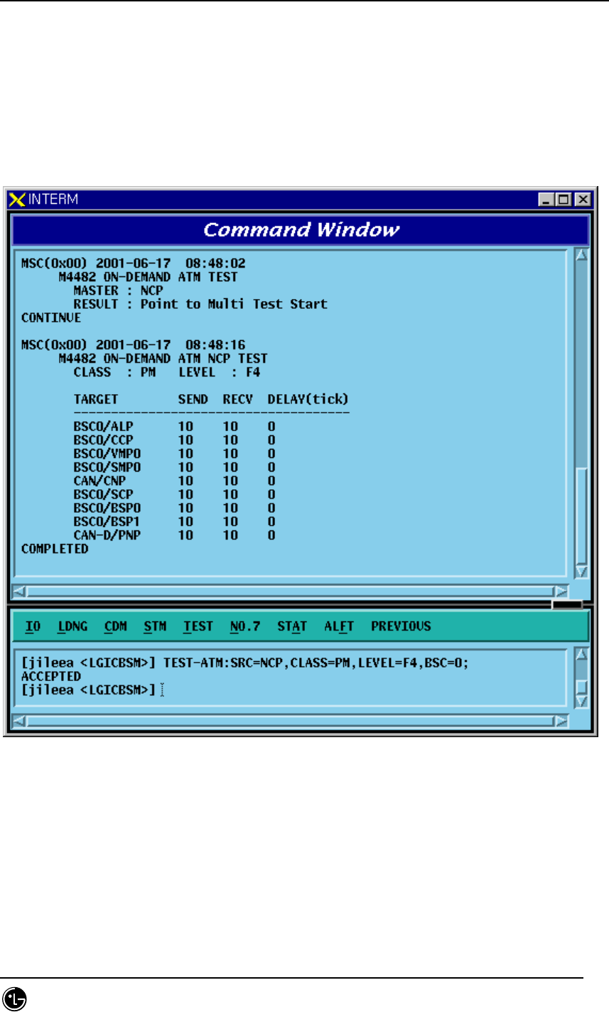
STAREX-IS BSM Manual
Page:438(877)
Issue:1.
0
SMD-011-PMA210
d: Test Level(F4: VPC, F5: VCC)
e: BSC number(0~11)
f: BTS number(0~47)
g: SMP number(0~5)
h: VMP number(0~7)
i: PCF number(0~2)
• Input/Output
Fig. 4.5-15 Result of ATM Path(PM) Test Performance
STAREX-IS BSM Manual
Page:439(877)
Issue:1.
0
SMD-011-PMA210
Fig. 4.5-16 Result of ATM Path(CC) Test Performance
STAREX-IS BSM Manual
Page:440(877)
Issue:1.
0
SMD-011-PMA210
Fig. 4.5-17 Result of ATM Path(LB) Test Execution

STAREX-IS BSM Manual
Page:441(877)
Issue:1.
0
SMD-011-PMA210
4.5.5. Command related to BSC Virtual Call Test
General mobile call is ㅡmade by MS, BSS(BSC, BTS), switching system interworking.
Because the section between MS and BSS is the place where call environment setup
function and modulation and demodulation of voice data are made including allocation
of call resource necessary for radio communication, it is responsible for essential
function in the mobile communication system. Testing call is the function to check the
following: 1) the presence of faults in call processing made between BSS and MS that
excludes the MSC function in the course of mobile call processing, and 2) the quality
of voice. Since it excludes the MS function to, mutual calls such as M2L, L2M, or M2M
cannot be made; however, , but cantest can be perfomed by selecting one between
originating and terminating call. When a testing call was set up, BSS and MS generate
markov data and exchange them and by checking if there is any loss of markov data,
they calculate quality of voice. Terminating call inputs IMSI value of MS to be tested in
BSM and trys paging to set up a call. And Originating call sets up a call by selecting
testing call function of MS. (Originating call is not related to BSM function.)
• BSC Testing Call
It checks the following: 1) if there is any faults in call processing that is carried out
between BSC(SLP) – BTS(CE) - MSs and 2) the quality of voice. If a Call is attempted
in BSM by inputting the the information (i.e., the number of MS, BSC number, BTS
number, sector, frequency resource, MS call setup data (Station Class Mark, Slot Cycle
Index), Service Option(13K Markov, 8K Markov, 13K LoopBack, 8K LoopBack), and
voice packet data rate(Full, half, Quarter, Eighth , Variable rate)), then Call Link
between SLP-CE-MS is set up (setup of testing call) according to the data input. Once
a Call is set up, SLP and MS calculate Frame Error Rate while exchanging markov data.
When a Call is set up and a Call is released, BSM displays data of call resource, FER,
and reason for release.
• Service Option
Service Options of present use for Testing call at BSC include 8K Markov, 13K Markov,
8K loopback, 13K loopback .
• Markov
Once Testing Call is set up, SLP and MS synchronizes their time, and generate
identical data in sequence by Markov Algorithm. SLP and MS receive each other’s data
and compare them with their own to detect errors in the data frame. It can obtain
Forward FER(measured at MS) and Reverse FER(measured at SLP).
LoopBack: When Testing Call is set up, SLP generates voice data and sends them to
MS. MS performs lookback on this data as it is and SLP compares returned data with

STAREX-IS BSM Manual
Page:442(877)
Issue:1.
0
SMD-011-PMA210
the original data to validate the quality of voice. (FER measured at SLP)
• Data Rate
User can designate voice data rate to be used for testing call. The data rate is divided
into the following: Full rate, Half rate, Quarter rate, Eighth rate, and Variable rate.
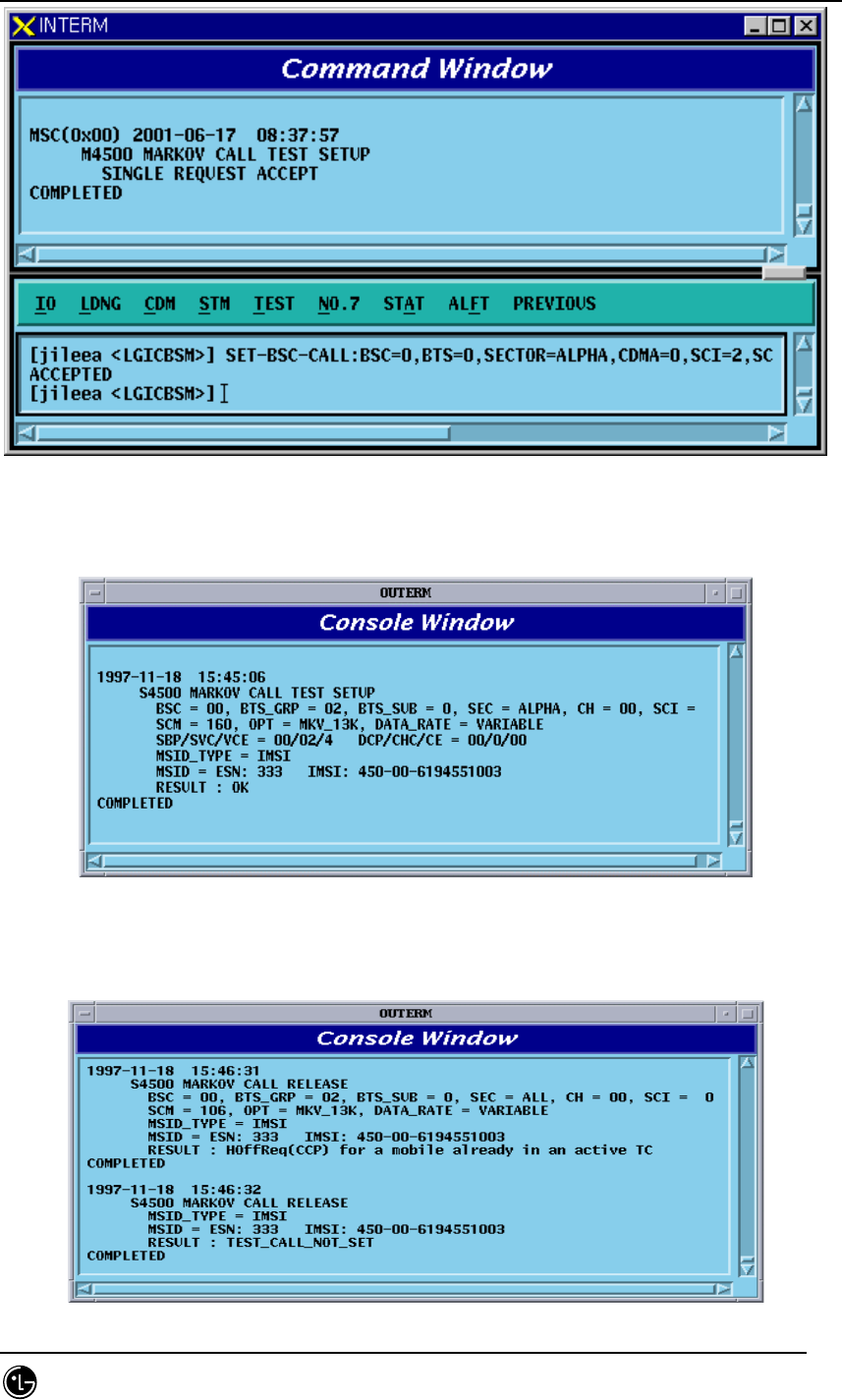
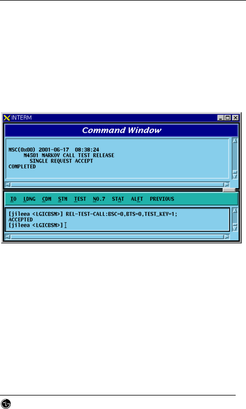
4.5.5.1. BSC Virtual Call Setup Function
Function to designate various options and setting up Call to a specific MS or all the
MSs MS to be tested should be entered to BSM DB with INS-TEST-MS command.
When TEST_KEY is not input, testing calls are set up for all the MSs stored in DB.
Testing Call is attempted for 60 minutes at a maximum. Once a Call is set up, it is
maintained for 60 minutes. If a call is disconnected due to the occurrence of faults, or
when a user released the call at random, a message for the reason of call release is
displayed.
• Command SET-TEST-CALL :BSC=a ,BTS=b ,SECTOR=c ,CDMA=d ,SCI=e ,SCM=f ,
OPTI=g ,DTYPE=h ,TIME=i [,TEST_KEY=j];
a: BSC number (0~11)
b: BTS number (0~47)
c: sector (ALPHA/BETA/GAMMA/DELTA/ZETA/EPSILON)
d: CDMA number (0~11)
e: SLOT CYCLE Index (0~7)
f: SLOT mode (SLOT_M, NON_SLT_M)
g: option (MKV_13K/MKV_8K/LB_13K/LB_8K)
h: Data Rate (VARIABLE/FULL/HALF/QUART/EIGHT )
i: TIME(1~60min)
j: Test Key(1 ~ 100)
• Input/Output
STAREX-IS BSM Manual
Page:443(877)
Issue:1.
0
SMD-011-PMA210
Fig. 4.5-18 BSC Virtual Call Setup Command INTERM Display
Fig. 4.5-19 Console Window Display at the setup of BSC Virtual Call
STAREX-IS BSM Manual
Page:444(877)
Issue:1.
0
SMD-011-PMA210
Fig. 4.5-20 Display at the Termination of BSC Virtual Call
4.5.5.2. Virtual Call Release Function
Function to release a call for a specific MS or all the MSs where a virtual call set up.
The output resulting from virtual call release is displayed by "Release by MMC".
• Command REL-TEST-CALL :BSC=a ,BTS=b [,TEST_KEY=c];
a: BSC number (0~11)
b: BTS number (0~15)
c: TEST KEY(1~100)
• Input/Output
Fig. 4.5-21 Result of BSC Virtual Call Release Command Execution
4.5.5.3. Testing MS Display Function
Function to display MSs to be used for the BSC Virtual Call test.
• Command DIS-TEST-MS :BSC=a ,BTS=b;
a: BSC number (0~11)
b: BTS number (0~47)
• Input/Output
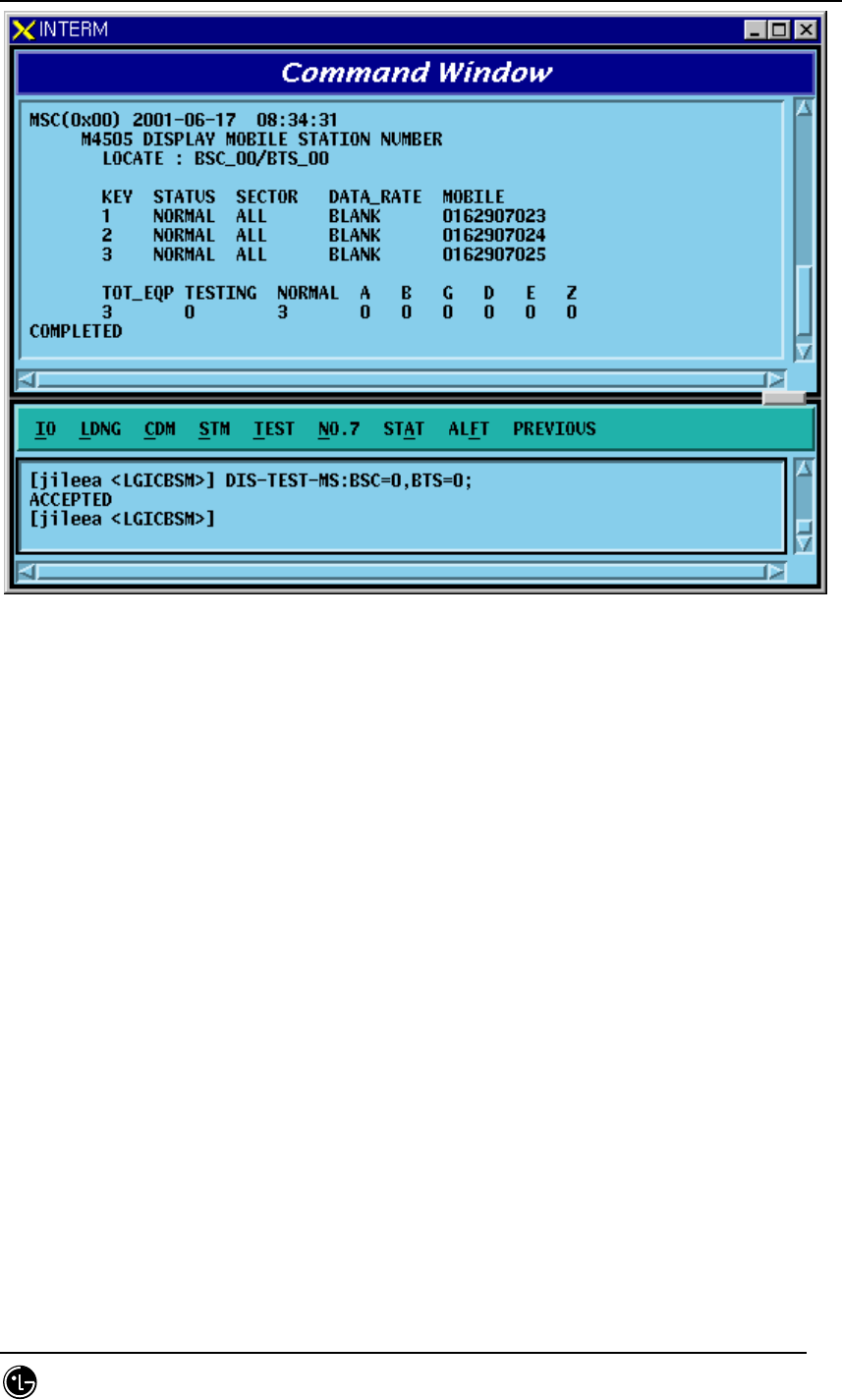
STAREX-IS BSM Manual
Page:445(877)
Issue:1.
0
SMD-011-PMA210
Fig. 4.5-22 Presently registered Testing MS Display
4.5.5.4. MS Supplementary Function
Function to register MS to be used for the BSC Virtual test.
For a test of virtual call, first register MS.
• Command INS-TEST-MS :BSC=a ,BTS=b ,TEST_KEY=c [,MSIN=d];
a: BSC number (0~11)
b: BTS number (0~47)
c: TEST KEY(1~100)
d: IMSI of MS
• Input/Output
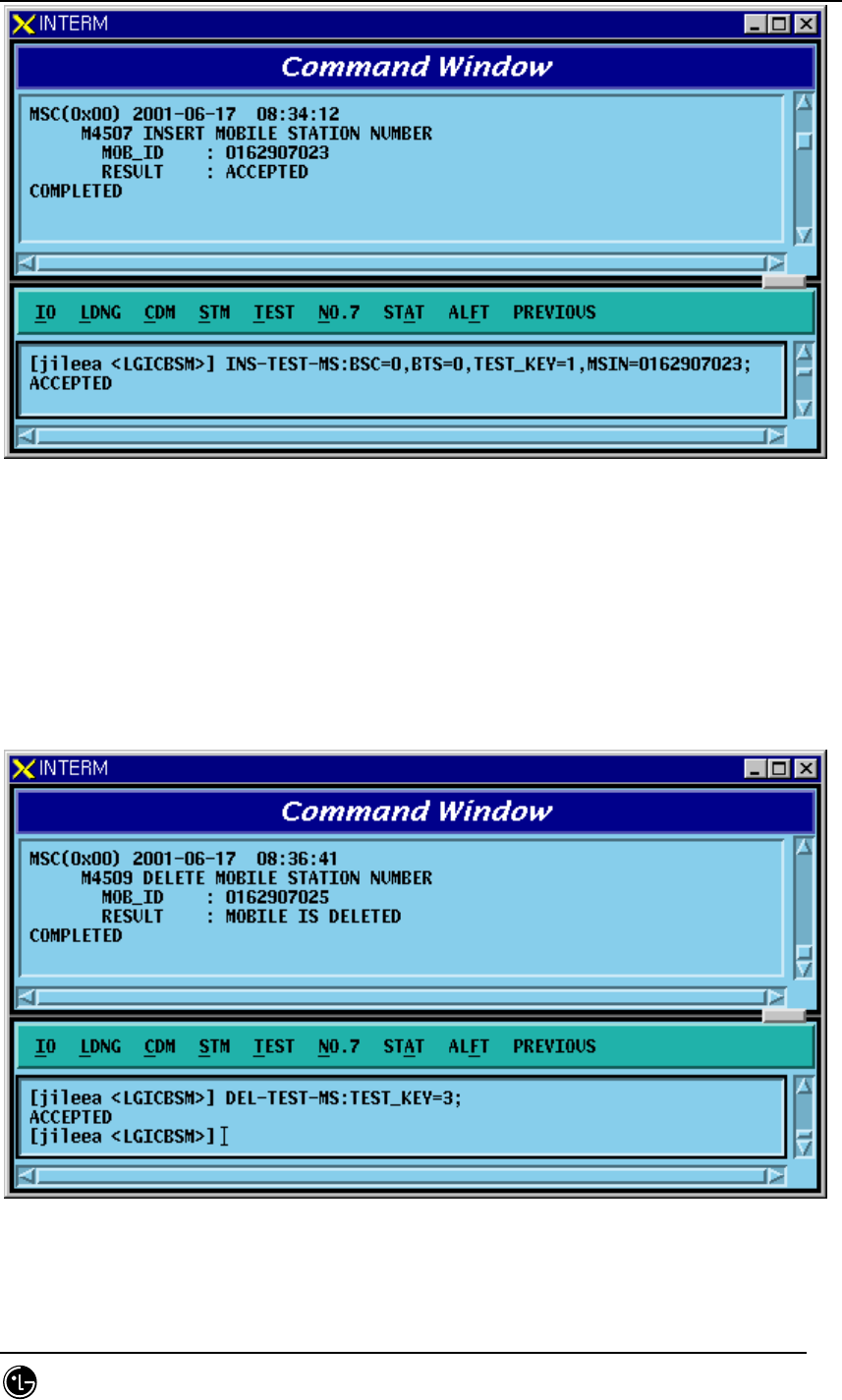
STAREX-IS BSM Manual
Page:446(877)
Issue:1.
0
SMD-011-PMA210
Fig. 4.5-23 Testing MS Insert Result Display
4.5.5.5. MS Delete Function
Function to delete MS registered on the test list of BSC Virtual Call
• Command DEL-TEST-MS :TEST_KEY=a;
a: TEST_KEY of Mobile to be deleted
• Insert/Output
Fig. 4.5-24 Delete MS Execution Result

STAREX-IS BSM Manual
Page:447(877)
Issue:1.
0
SMD-011-PMA210
4.5.6. TRAFFIC PATH TESTING FUNCTION
it is a test enabling to decide if there is presence of failure with designated traffic
path by setting a traffic path for BSC virtual call for a specific MS with the designated
call resources and then measuring PER.. The kinds of virtual call include Markov and
Loop Back., There are 8K and 13K respectively by service option. Call resources that
the user can designate are as follows: Selector Slave Processor, Trunk, and BTS
channel Chip. In one BSC, 100 virtual calls can be set up simultaneously separated
from testing function of virtual call. Once a call is set up, a message type which is
identical to the message type coming from BSC virtual call setup process is displayed.
4.5.6.1. Traffic Path Testing Setup Function
Function to set up a Call for the designated Traffic Path
• Command SET-PATH-CALL : IMSI=a , BSC=b , SMP=c , SLP=d , SLPSLV = e [,TRK =
f], BTS= g ,SECTOR = h ,CDMA = i ,RCP= j , MCPA=k , CHIP=l , SCI=m , SCM=n ,
OPTI=o , DTYPE=p [,TIME=q];
a : IMSI
b : BSC_Number(0~11)
c : SMP_Number(0~4)
d : SLP_Number(0~19)
e : SLP_Slave_Number(0~3)
f : Trunk_Number(0~19)
g : BTS_Number(0~47)
h : Sector_Id(0~5)
i : CDMA_Channel_Number(0~11)
j : RCP_Number(0~9)
k : MCPA_Number(0~9)
l : CHIP_Number(0~1)
m : Slot_Cycle_Index(0~7)
n : Station_Class_Mark(SLOT_M, NON_SLT_M)
o : Service_Option(MKV_13K, MKV_8K, LB_13k, LB_8K)
p : Test_data_Type(VARIABLE, RATE_FULL, RATE_HALF, RATE_QUAR, RATE_EIGHT)
q : TRACE_TIME(1~60min)
• Input/Output
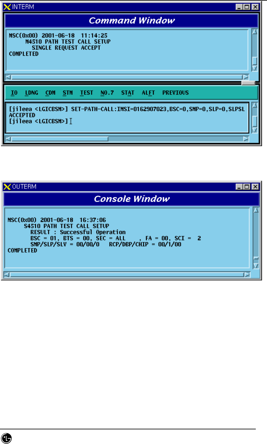
STAREX-IS BSM Manual
Page:448(877)
Issue:1.
0
SMD-011-PMA210
Fig. 4.5-25 Traffic Path Setup Command Execution Result Display(Interm Window)
Fig. 4.5-26 Traffic Path Setup Command Execution Result Display(Console Window)
4.5.6.2. Traffic Path Release Function
Function to release a Call to MS of a specific BSC, BTS where a virtual call is set up.
• Command REL-PATH-CALL :BSC=a ,BTS=b;
a: BSC number (0~11)
b: BTS number (0~15)
• Input/Output
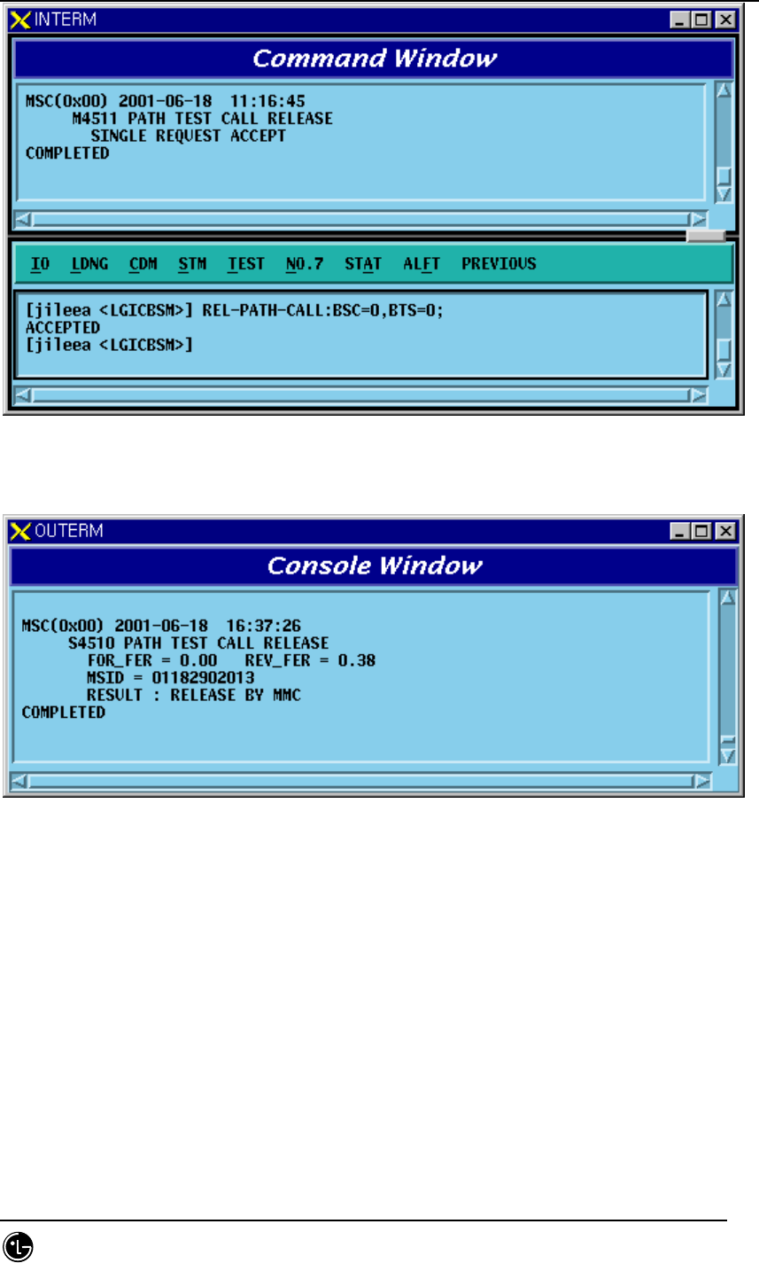
STAREX-IS BSM Manual
Page:449(877)
Issue:1.
0
SMD-011-PMA210
Fig. 4.5-27 Traffic Path Release Command Execution Result Display(Interm Window)
Fig. 4.5-28 Traffic Path Release Command Execution Result Display(Console Window)

STAREX-IS BSM Manual
Page:450(877)
Issue:1.
0
SMD-011-PMA210
4.5.7. Call Trace Testing Function
Mobile Call Trace Function traces the process of call setup for the MS, surveillance of
the status after the call setup, the process of call release, and displays the content
visibly to BSM after BSM of User’s terminal designates a Mobile Station(MS) at
random by using a value of MSIN(Mobile Station Identification Number). . The
designated Mobile Station(MS) can trace the originating call or terminating call that
was set up by the user and if necessary, it sets up Markov call(i.e., a terminating
Markov call by paging) for tracing. Mobile call tracing can be performed to all kinds of
calls(Voice Call, Data Call, HandOff Call) and can designate maximum two calls
simultaneously for tracing. Information provided upon call tracing is as follows:
Tracing Information when Call is set
Resource of Call to be set
System Resource: BSC No, BTS No, Sector No, PN Offset
Attributes of Call: IMSI, ESN, Service Option, Call Type(Voice Call originating, Voice
Call terminating, DATA Call initial set, DATA Call Reactivation by MS, DATA Call
Reactivation by Network), Terminating number
BTS Resource: CDMA CH(Frequency) No, TC No(RCP#, MCPA#, CE#),
Code CH(Walsh code), Frame Offset
BSC Resource: SLP, VCE Number, CIC(Circuit Identifier Code)
Setup Process
Message display between processors during Call Setup: Visible Display of Call Flow
During Call Setup, display RTD(Round Trip Delay) value and calculated distance by
using this.
When Call Failure occurs, display reason value and its meaning
Call Set Time by section
Tracing Information at the phase of calling after Call Setup: Tracing and Display at
intervals of 1 ~ 5 seconds.
Elements of Communication Quality
Forward FER(Frame Error Rate): Present FER, Total FER
Backward FER(Frame Error Rate): Present FER, Total FER
Power Control Parameter: TC Gain, Reverse Power Control Threshold
Location Estimate Elements
Present Active PN Offsets Aggregation : BSC No, BTS No, Sector, Cdma Ch,
Walsh_ch, TC Id, RTD
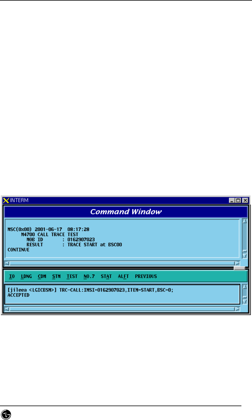
STAREX-IS BSM Manual
Page:451(877)
Issue:1.
0
SMD-011-PMA210
Present RTD Value and calculated distance by using this
Tracing Information at the phase of Call Release: Tracing it every time at the normal
release or abnormal release
Reason for Call Release
Reason for Call Release and its content: Display reason value and its meaning
Quality Elements of Call
Forward Total FER(Frame Error Rate)
Backward Total FER(Frame Error Rate)
4.5.7.1. Call Trace Start/End Function
Function that starts/ends Call Trace with MS designated at random.
• Command TRC-CALL : IMSI=a, ITEM=b,BSC=c;
a: IMSI Number
b: Start / Stop
c: BSC ID
• Input/Output
Fig. 4.5-29 Call Trace Start Command Input Screen
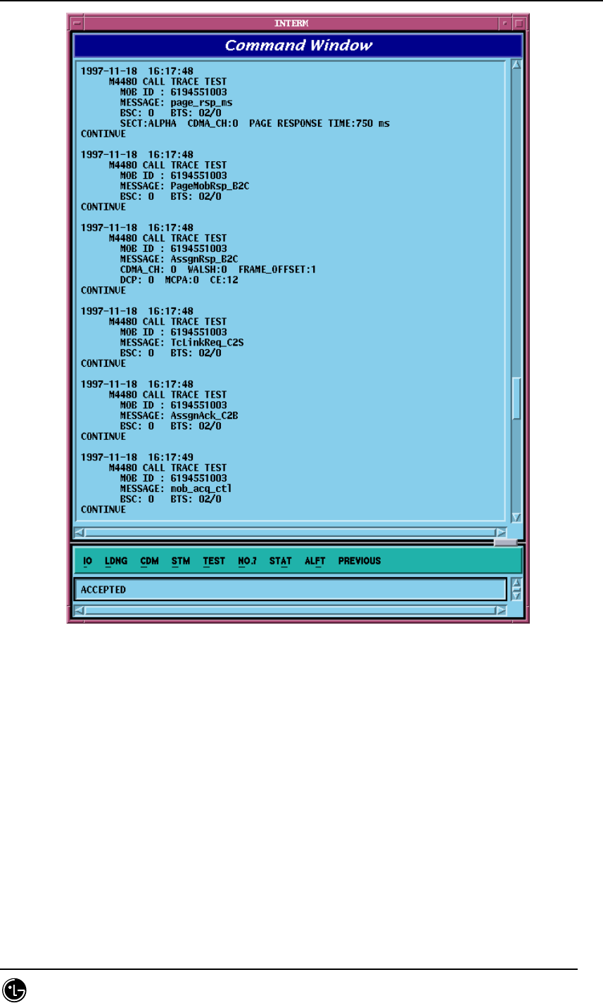
STAREX-IS BSM Manual
Page:452(877)
Issue:1.
0
SMD-011-PMA210
Fig. 4.5-30 Call Trace Display in the Process of Call Set
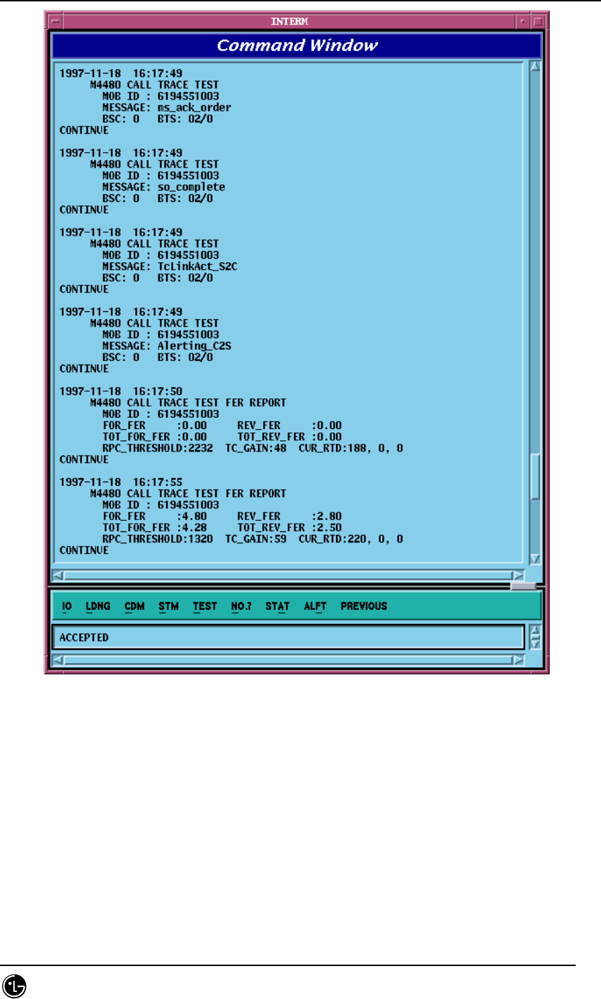
STAREX-IS BSM Manual
Page:453(877)
Issue:1.
0
SMD-011-PMA210
Fig. 4.5-31 Display of Call Set Process and Elements of Communication Quality
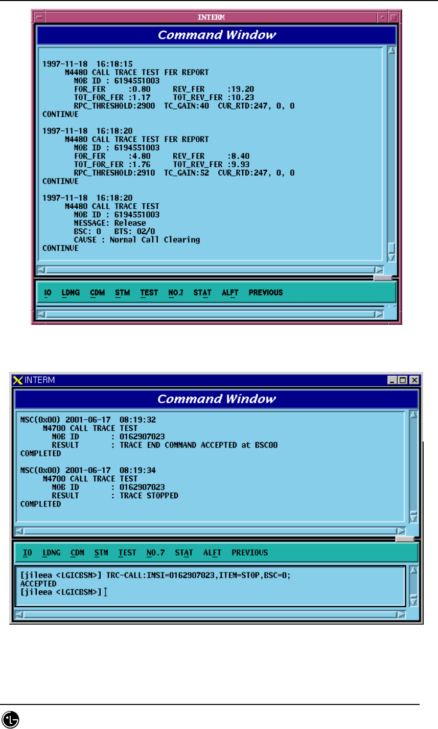
STAREX-IS BSM Manual
Page:454(877)
Issue:1.
0
SMD-011-PMA210
Fig. 4.5-32 Display of Communication Quality and Release Reason
Fig. 4.5-33 Call Trace Stop Result
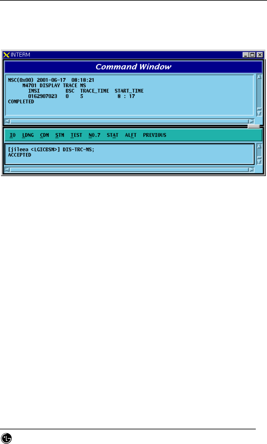
STAREX-IS BSM Manual
Page:455(877)
Issue:1.
0
SMD-011-PMA210
4.5.7.2. Call Trace MS Display Function
Function to display MS that currently uses the mobile call tracing function.
• Command DIS-TRC-MS;
• Input/Output
Fig. 4.5-34 Terminal Display in use of Call Trace
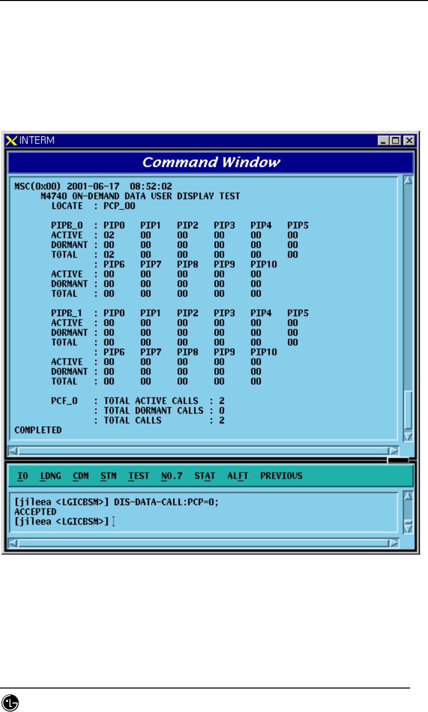
STAREX-IS BSM Manual
Page:456(877)
Issue:1.
0
SMD-011-PMA210
4.5.8. Number of Data Call User Display Function
(Active/Dormant)
Function to display Number of Data Call by Active/Dormant
• Command DIS-DATA-CALL:PCP=a;
a: PCP Number(0~2)
• Input/Output
Fig. 4.5-35 Result of the Number of DATA Call User Display
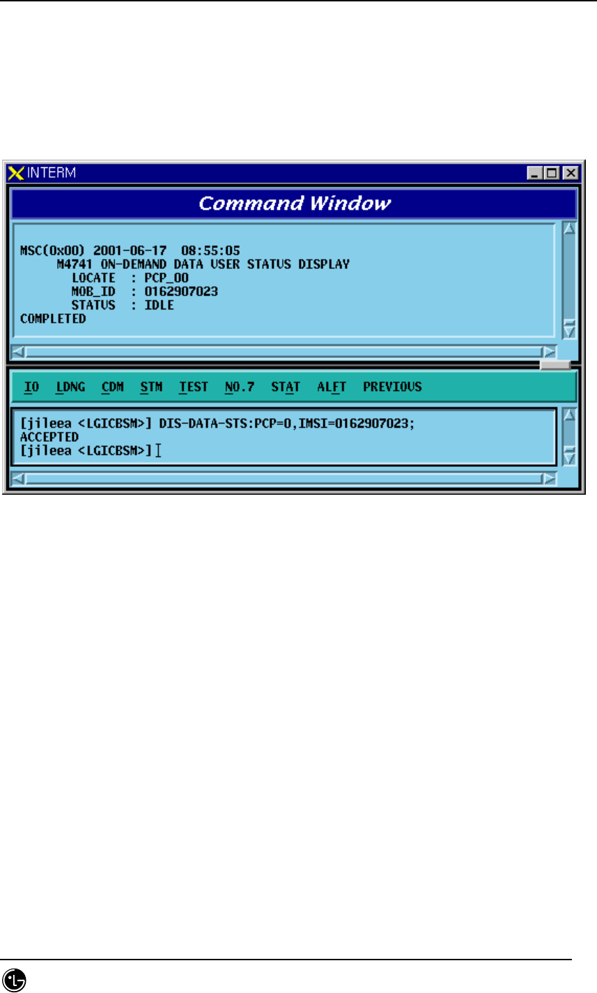
STAREX-IS BSM Manual
Page:457(877)
Issue:1.
0
SMD-011-PMA210
4.5.9. DATA Call User Status Display Function by IMSI
Command DIS-DATA-STS:PCP=a,IMSI=b;
a: PCP Number(0~2)
b: IMSI of MS
• Input/Output
Fig. 4.5-36 Result of DATA Call User Status Display by IMSI
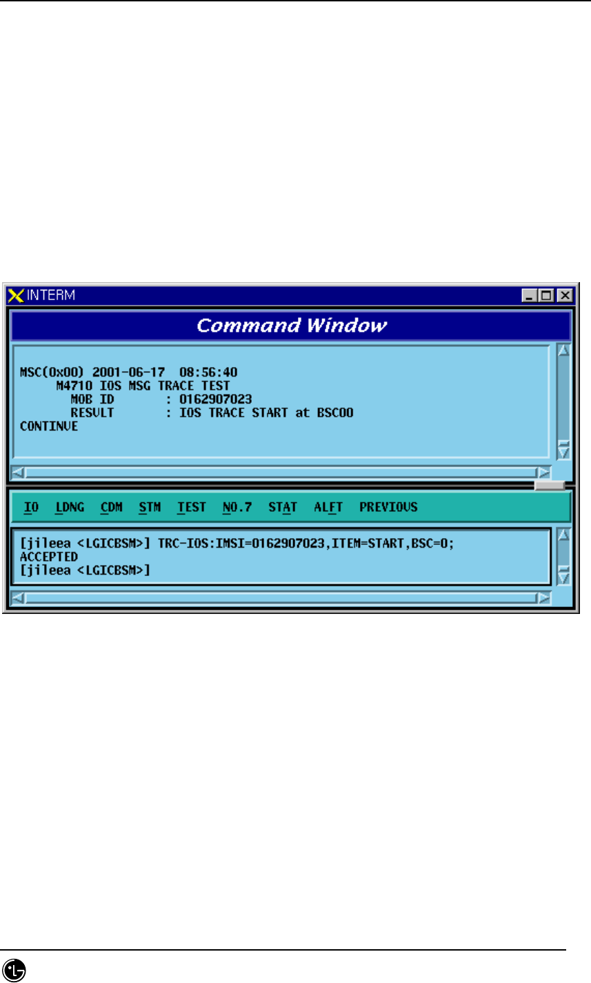
STAREX-IS BSM Manual
Page:458(877)
Issue:1.
0
SMD-011-PMA210
4.5.10. IOS Message Display Function
This function is operated by inputting the IMSI of MS to trace, duration, etc in BSM and
displays IOS trace information for all kinds of calls that MS attempts as visible
information in text format in the BSM.
• Command TRC-IOS : MS=a, BSC=b, FLAG=c, DURATION=d
a: MS Number
b: BSC ID(0~11)
c: Start/Stop
d: Trace Duration Time
• Input/Output
Fig. 4.5-37 IOS Message Display START Result
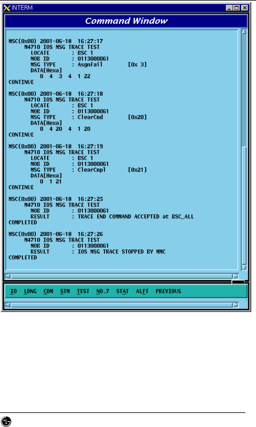
STAREX-IS BSM Manual
Page:459(877)
Issue:1.
0
SMD-011-PMA210
Fig. 4.5-38 IOS Display Message
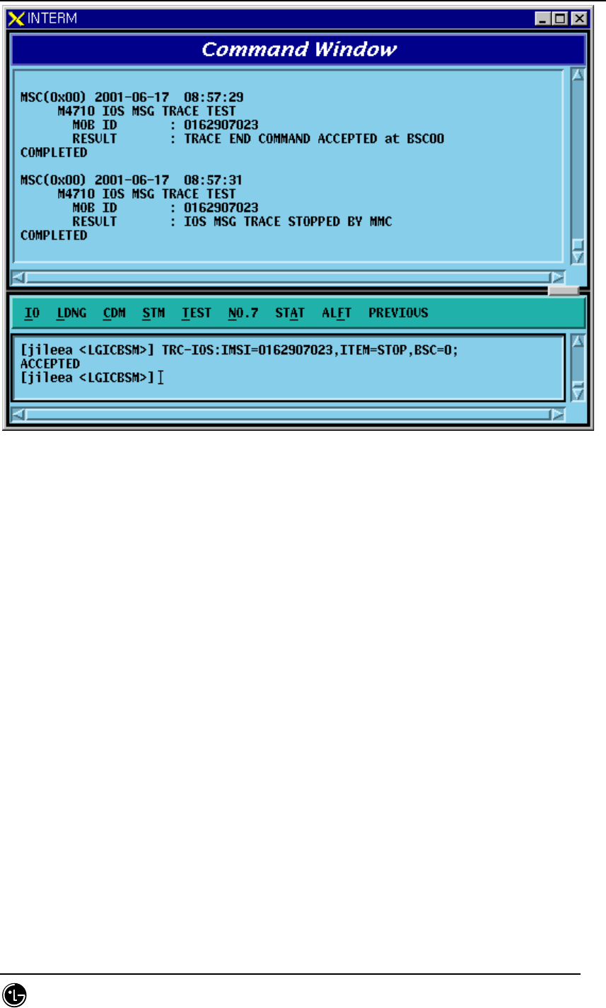
STAREX-IS BSM Manual
Page:460(877)
Issue:1.
0
SMD-011-PMA210
Fig. 4.5-39 STOP Result of IOS Message Display Function
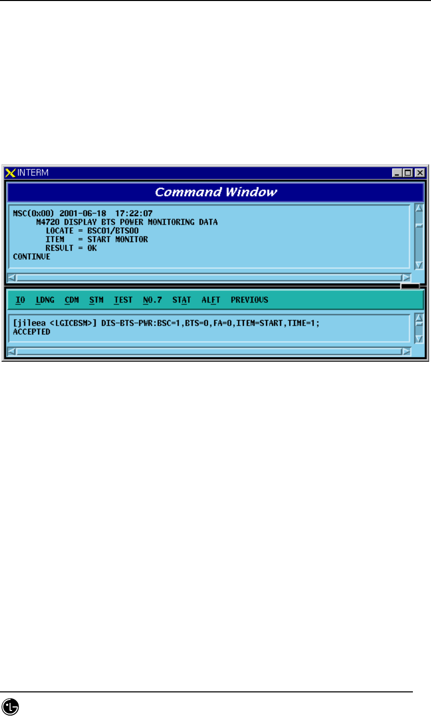
STAREX-IS BSM Manual
Page:461(877)
Issue:1.
0
SMD-011-PMA210
4.5.11. POWER MONITORING Function
Function to check the BTS power control in BSM
• Command DIS-BTS-PWR:BSC=a,BTS=b,ITEM=c,[TIME=d]:
a: BSC ID(0~11)
b: BTS ID(0~47)
c: Stop/Start
d: Duration Time(1~100 min)
• Input/Ouput
Fig. 4.5-40 Power Monitoring START Result
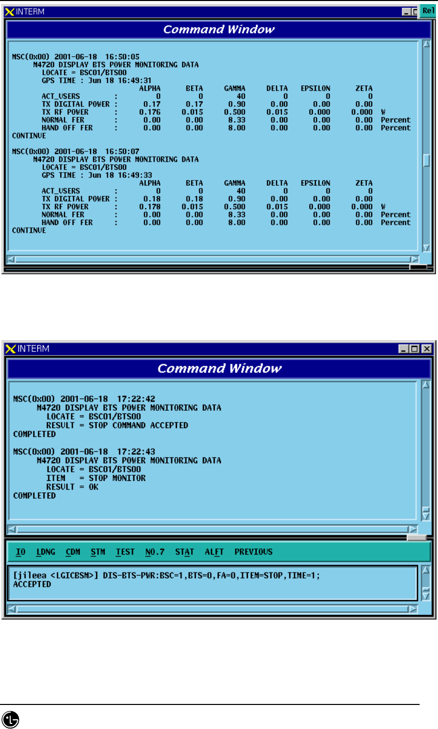
STAREX-IS BSM Manual
Page:462(877)
Issue:1.
0
SMD-011-PMA210
Fig. 4.5-41 Power Monitoring Result
Fig. 4.5-42 Power Monitoring STOP Result
STAREX-IS BSM Manual
Page:463(877)
Issue:1.
0
SMD-011-PMA210
4.6. No.7 Command
The function of BSM No.7 is to manage parameter information necessary for the
operator to operate No.7. It is divided into the following function: 1) signaling link
operation management and 2) the signaling link maintenance. The former is composed
of the following: signaling point management function, signaling link set management
function, signaling link management function, signaling terminal management function,
signaling data management function, and SCCP management function. The latter is
composed of signaling link and signaling terminal test, and signal link inhibit.
4.6.1. Related Command
4.6.1.1. Commands for Signaling Link Operation and Management
Function
Table 4.6-1 Commands related to Signaling Point Management
Commands Description
DIS-SP-INFO Signaling Point Information Display
CHG-OSP Change of Intra-Switching Office Signaling Point
CHG-SP Change of Signaling Point
Table 4.6-2 Commands related to Signaling Link Set
Commands Description
ACT-LKS Signaling Link Set Activation
DACT-LKS Signaling Link Set Deactivation
Table 4.6-3 Commands related to Signaling Link
Commands Description
CRET-SLK Signaling Link Create
DEL-SLK Signaling Link Deletion
ACT-SLK Signaling Link Activation
DACT-SLK Signaling Link Deactivation
STAREX-IS BSM Manual
Page:464(877)
Issue:1.
0
SMD-011-PMA210
DIS-SLK-INFO Signaling Link Information Display
INH-SLK Signaling Link Barring
ALW-SLK Signaling Link Barring Release
Table 4.6-4 Commands related to Signaling Terminal
Commands Description
CRTE-ST Signaling Terminal Definition(Create)
DEL-ST Signaling Terminal Deletion
DIS-ST-INFO Signaling Terminal Information Display
Table 4.6-5 Commands related to Signaling Data Link
Commands Description
CRTE-SDLK Signaling Data Link Definition(Create)
DEL-SDLK Signaling Data Link Deletion
DIS-SDLK-INFO Signaling Data Link Information Display
Table 4.6-6 Display Commands for SCCP Data
Commands Description
DIS-SCCP-NET SCCP Network Configuration Data Display
DIS-SCCP-LSS SCCP Intra-Switching Office Sub-system Status Data
Display
Table 4.6-7 Signaling Link Status Display Commands
Commands Description
DIS-SLK-STS Signaling Link Status Display
DIS-ST-STS Signaling Terminal Status Display
DIS-LKS-STS Signaling Link Set Status Display
Table 4.6-8 Commands related to Timer
STAREX-IS BSM Manual
Page:465(877)
Issue:1.
0
SMD-011-PMA210
Commands Description
DIS-MTP2-TMR MTP L2 Timer Display
CHG-MTP2-TMR MTP L2 Timer Change
DIS-MTP3-TMR MTP L3 Timer Display
CHG-MTP3-TMR MTP L3 Timer Change
DIS-SCCP-TMR SCCP Timer Change
CHG-SCCP-TMR SCCP Timer Change
4.6.1.2. Commands for Signaling Link Maintenance Function
Table 4.6-9 Test Related Commands
Commands Description
TEST-SLK Signaling Link Test
TEST-ST Signaling Terminal Test
DIS-No7-CYC Test Cycle Display
CHG-No7-CYC Test Cycle Change
Table 4.6-10 Status Suppression Related Commands
Commands Description
DIS-INH-NO7 Displayable Status Message Display
ALW-N07-MSG Status Message Display Possible
INH-NO7-MSG Status Message Display Suppression
4.6.2. Signaling Link Operation Management Function
4.6.2.1. Signaling Point Information Display
Display the Status of Signaling Point of local Switching Office and that of Intra-
Switching Office.
Command DIS-SP-INFO:BSC_ID=a
a = BSC Number (00 ~ 11)
Input DIS-SP-INFO:BSC_ID=0;
STAREX-IS BSM Manual
Page:466(877)
Issue:1.
0
SMD-011-PMA210
Output
Fig. 4.6-1 Signaling Point Information Display
4.6.2.2. Change of Intra-Switching Office Signaling Point
It changes Information for Intra-Switching Office Signaling Point.
Command CHG-OSP:BSC=a,OSP_NUM=b;
a = BSC Number( 00 ~ 11 )
b= OSP Number ( 00 ~ 65535 )
Input CHG-OSP:BSC_ID=0,OSP_NUM=5;
Output
Fig. 4.6-2 Change of Intra-Switching Office Signaling Point
4.6.2.3. Change of Local Switching Office Signaling Point
It changes Signaling Point of Local Switching Office.
Command CHG-SP-INFO:BSC_ID=a, SP_NUM=b
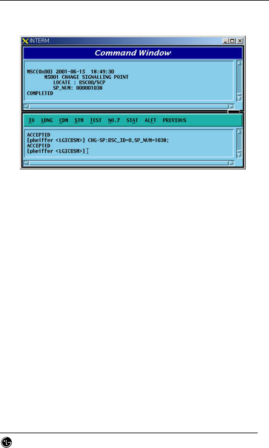
STAREX-IS BSM Manual
Page:467(877)
Issue:1.
0
SMD-011-PMA210
b = SP Number ( 00 ~ 65535 )
Input CHG-SP-INFO:BSC_ID=0,SP_NUM=1038
Output
Fig. 4.6-3 Change of Remote Switching Office Signaling Point
4.6.2.4. Activation of Signaling Link Set
Signaling Link Set indicates an aggregation of signaling links(Max 16 units). Activation
of Signaling Link Set is to put all the defined Signaling Links in a in-service status.
Command ACT-LKS:BSC_ID=a
a = BSC Number ( 00 ~ 11)
Input ACT-LKS:BSC_ID=0;
Output
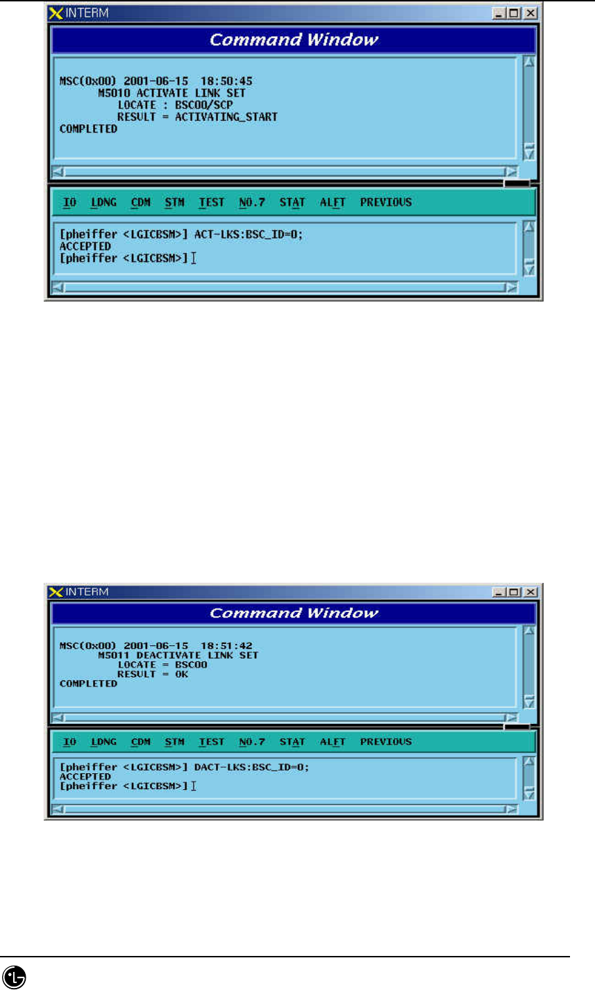
STAREX-IS BSM Manual
Page:468(877)
Issue:1.
0
SMD-011-PMA210
Fig. 4.6-4 Activation of Signaling Link Set
4.6.2.5. Deactivation of Signaling Link Set
Function that puts all the defined Signaling Links in out-of-service status
Command DACT-LKS:BSC_ID=a;
a = BSC Number ( 00 ~ 01 )
Input DACT-LKS:BSC_ID= a;
Output
Fig. 4.6-5 Deactivation of Signaling Link Set
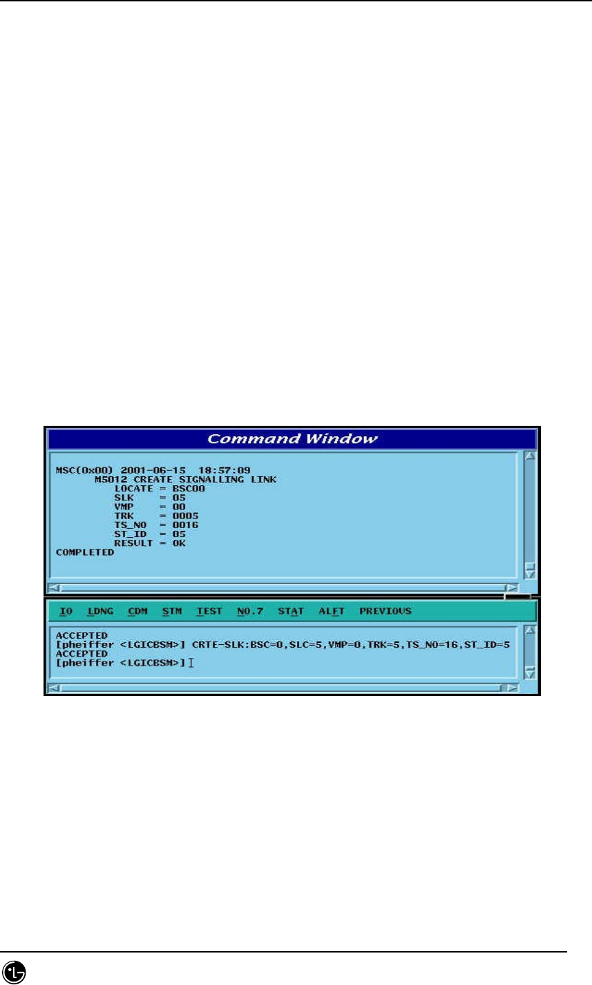
STAREX-IS BSM Manual
Page:469(877)
Issue:1.
0
SMD-011-PMA210
4.6.2.6. Signaling Link Generation
Signaling Link is the concept combing Signaling Data Link with Signaling Terminal. It
connects Intra-Switching Office Signaling Point to local switching Office Signaling
Point, and can define 16 units of Signaling Link. The definition of Signaling Link is used
to expand the number of Signaling Links. Before Signaling Link is defined, first of all,
Signaling Terminal and Signaling Data Link to be defined as Signaling Link should have
been defined.
Command CRTE-SLK:BSC=a, SLK=b, VMP=c, TRK=d, TS_NO = e, ST_ID =f;
a = BSC Number ( 00 ~ 11 )
b = Signalling Link Code ( 00 ~ 15 )
c = VMP ( 00 ~ 07 )
d = Trunk Number ( 00 ~ 16 )
e = Time Slot Number ( 00 ~ 31)
f = Signalling Terminal ( 1 ~ 16)
Input CRTE-SLK:BSC=0, SLK =5, VMP = 00, TRK = 5 TS_NO=16, ST_ID = 5;
Output
Fig. 4.6-6 Signaling Link Create
4.6.2.7. Signaling Link Deletion
Function to delete the defined Signaling Link.Before the Signaling Link is deleted, the
corresponding Signaling Link should have been successfully deactivated.
Command DEL-SLK:BSC_ID=a, SLC =b;
a = BSC Number ( 00 ~ 11 )
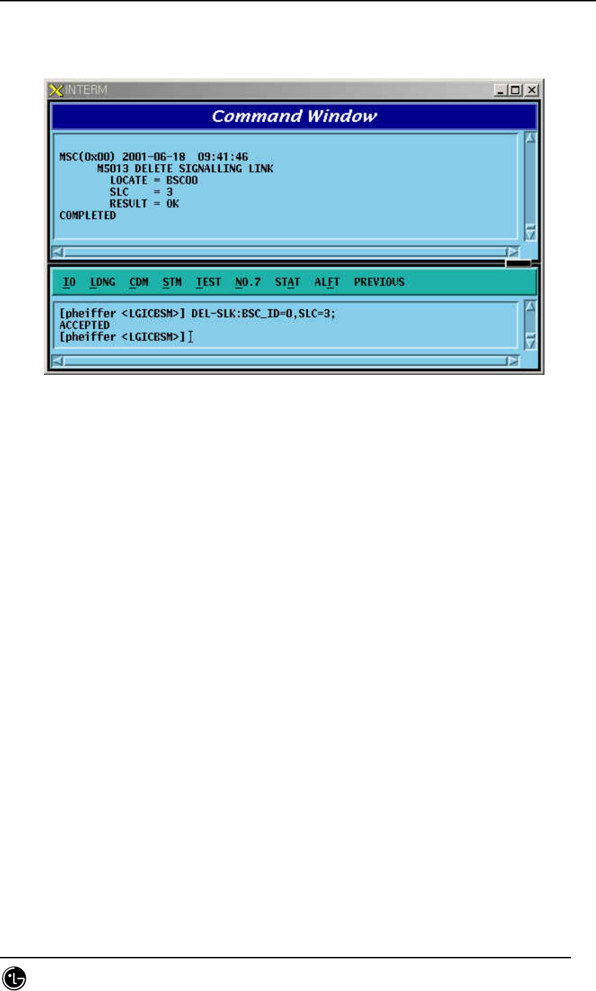
STAREX-IS BSM Manual
Page:470(877)
Issue:1.
0
SMD-011-PMA210
b = Signalling Link Code ( 00 ~ 15 )
Input DEL-SLK:BSC=0, SLC =3;
Output
Fig. 4.6-7 Deletion of Signaling Link
4.6.2.8. Signaling Link Activation
Function to activate a defined Signaling Link. Before activated, the corresponding
Signaling Link should have been successfully defined.
Command ACT-SLK:BSC_ID=a, SLC;
a = BSC Number ( 00 ~ 11 )
b = Signalling Link Code ( 00 ~ 15 )
Input ACT-SLK:BSC_ID=0, SLC=2;
Display
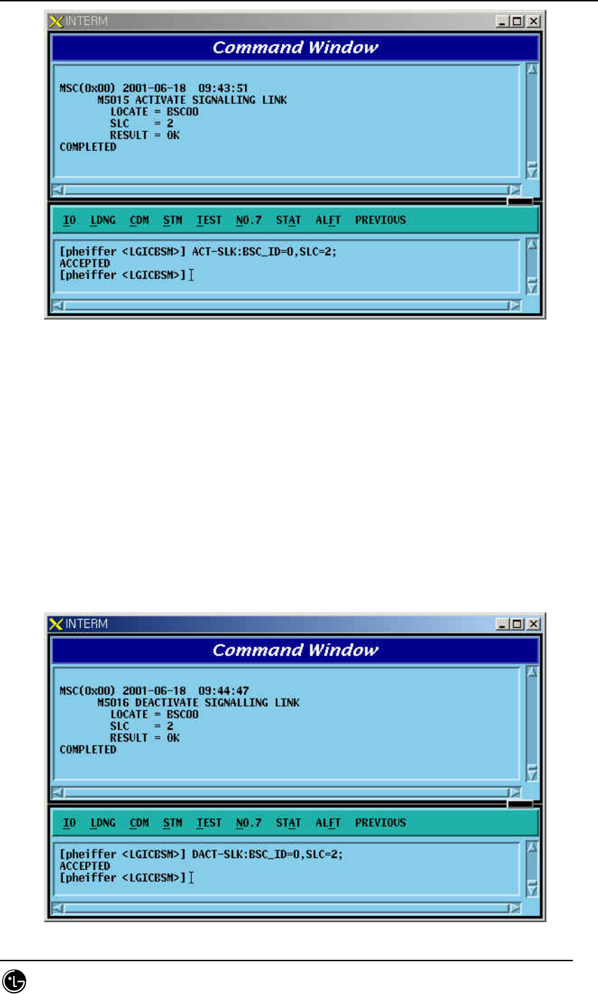
STAREX-IS BSM Manual
Page:471(877)
Issue:1.
0
SMD-011-PMA210
Fig. 4.6-8 Activation of Signaling Link
4.6.2.9. Signaling Link Deactivation
Function to deactivate the activated Signaling Link.
Command DACT-SLK:BSC=a, SLC=b;
a = BSC Number ( 00 ~ 11 )
b = Signalling Link Code ( 00 ~ 15 )
Input DACT-SLK:BSC_ID=0, SLC = 2;
Output
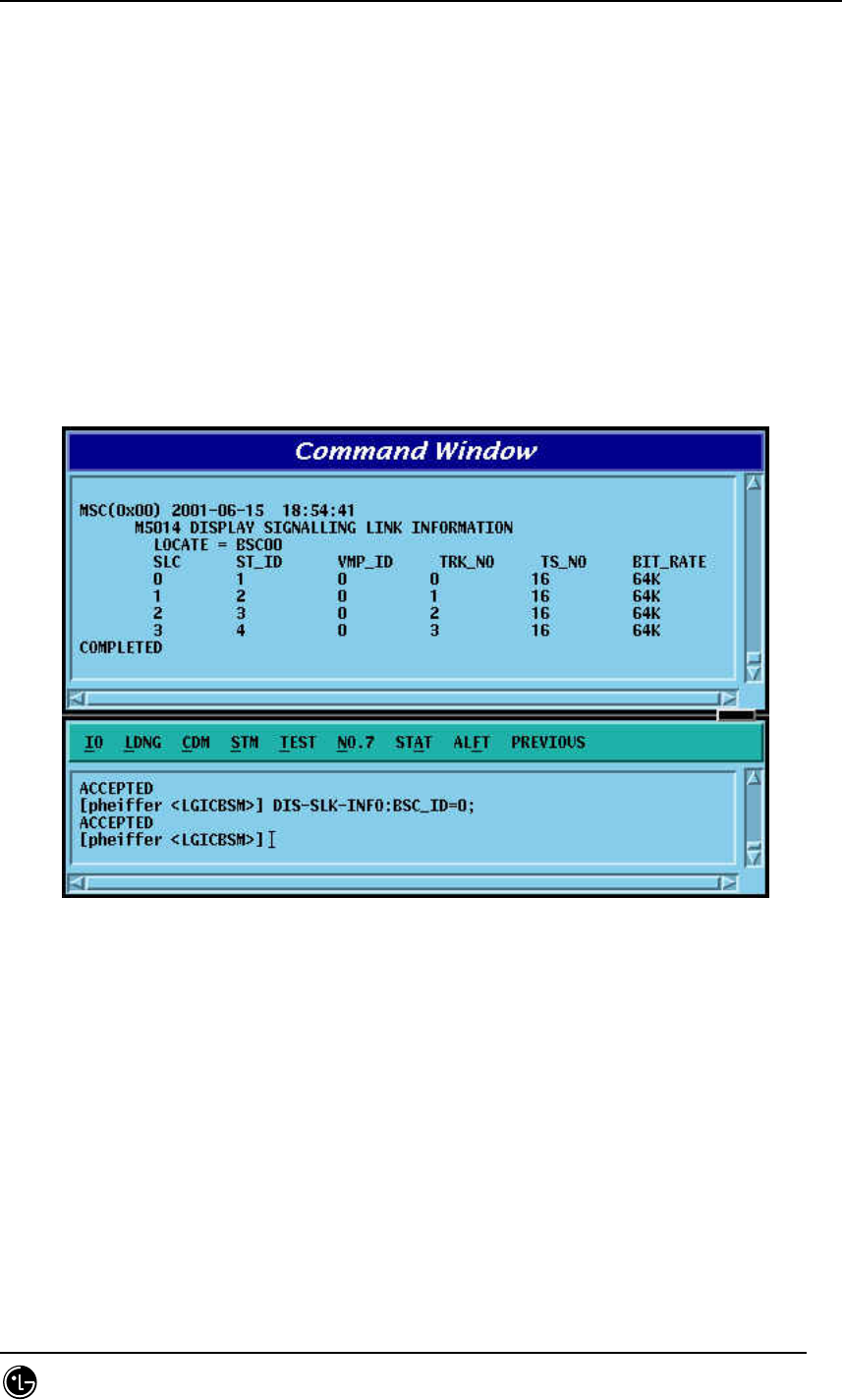
STAREX-IS BSM Manual
Page:472(877)
Issue:1.
0
SMD-011-PMA210
Fig. 4.6-9 Deactivation of Signaling Link
4.6.2.10. Signaling Link Information Display
Function to display information on Signaling Terminal, Signaling Data Link and Bit_Rate
connected to Signaling Link. It can display information on entire Signaling Links and on
Signaling Link designated.
Command DIS-SLK-INFO:BSC_ID=a;
a = BSC Number ( 00 ~ 15 )
Input DIS-SLK-INFO:BSC_ID = 0;
Output
Fig. 4.6-10 Signaling Link Information Display
4.6.2.11. Signaling Link Inhibition
It inhibits the use of presently defined Signaling Link.
Command INH-SLK:BSC_ID=0, SLC =0;
a = BSC Number ( 00 ~ 11 )
b = Signalling Link Code ( 00 ~ 15 )
Input INH-SLK:BSC_ID=0, SLC=0;
Output
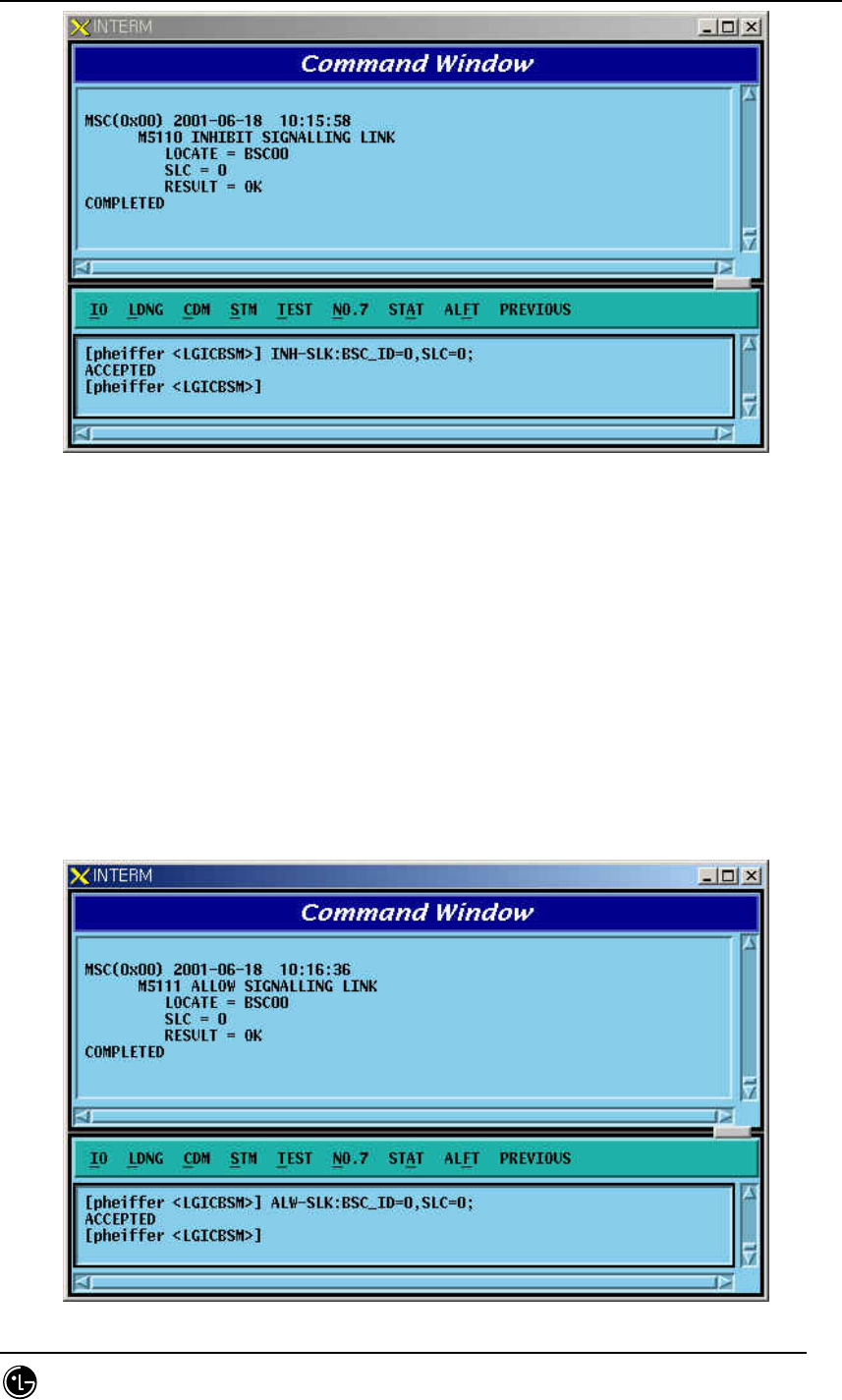
STAREX-IS BSM Manual
Page:473(877)
Issue:1.
0
SMD-011-PMA210
Fig. 4.6-11 Signaling Link Inhibit
4.6.2.12. Signaling Link Allow
Signaling Link Allow is a function that allows the management of Signaling Link
Status inhibited in the management of Signaling Link and then change to the status
of availability.
Command ALW-SLK:BSC_ID=0, SLC =0;
a = BSC Number ( 00 ~ 11 )
b = Signalling Link Code ( 00 ~ 15 )
Input ALW-SLK:BSC_ID = 0, SLC = 0;
Output
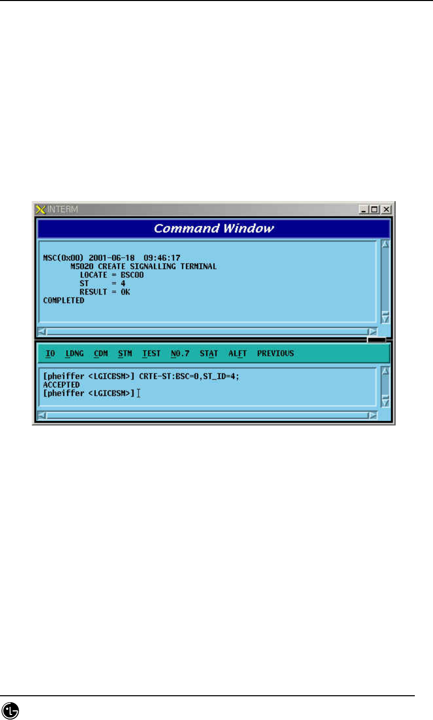
STAREX-IS BSM Manual
Page:474(877)
Issue:1.
0
SMD-011-PMA210
Fig. 4.6-12 Signal Link Allow
4.6.2.13. Signal Terminal Addition
Signal Terminal indicates physical name of a Channel of STPA and can define 16 units
of Signaling Terminal at a maximum. It is used to expand Signaling Terminal.
Command CRTE-ST:BSC=a, ST_ID=b;
a = BSC Number ( 00 ~ 15 )
b = Signalling Terminal ( 01 ~ 16 )
Input CRTE-ST:BSC_ID=0,ST_ID = 4;
Output
Fig. 4.6-13 Signaling Terminal Generation
4.6.2.14. Signaling Terminal Deletion
It is used when Signaling Terminal H/W has problems or other faults occur. Before
Signaling Terminal is deleted, make sure that the corresponding Signaling Terminal is
connected to Signaling Link.
Command DEL-ST:BSC=a, ST_ID =b;
a = BSC Number ( 00 ~ 11 )
b = Signalling Terminal ( 01 ~ 16 )
Input DEL-ST:BSC_ID=0,ST_ID = 5;
Output
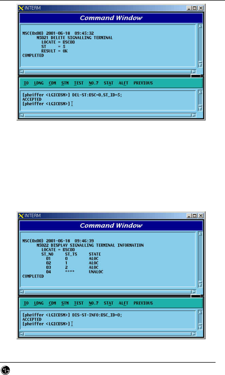
STAREX-IS BSM Manual
Page:475(877)
Issue:1.
0
SMD-011-PMA210
Fig. 4.6-14 Signaling Terminal Deletion
4.6.2.15. Signaling Terminal Information Display
Function to display information about if it is linked with signaling link to a specific
Signaling Terminal or all the Signaling Terminals.
Command DIS-ST-INFO:BSC_ID =a;
a = BSC Number ( 00 ~ 11 )
Input DIS-ST-INFO:BSC_ID = 0;
Output
Fig. 4.6-15 Display of Signaling Terminal Information
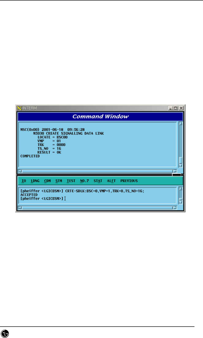
STAREX-IS BSM Manual
Page:476(877)
Issue:1.
0
SMD-011-PMA210
4.6.2.16. Signaling Data Link Addition
Signaling Data Link indicates Trunk Number to allocate as Signaling Link and is used
to expand Signaling Data Link.
Command CRTE-SDLK: BSC =a, VMP_ID=b, TRK= c ,TS_NO=d;
a = BSC Number ( 00 ~ 11 )
b = VMP Number( 00 ~ 07 )
c = TRUNK Number( 00 ~ 16 )
d = Time Slot Number( 00 ~ 31 )
Input CRTE-SDLK: BSC_ID=0, VMP_ID=1, TRK=0 , TS_NO=16;
Output
Fig. 4.6-16 Signaling Data Link Generation
4.6.2.17. Signaling Data Link Deletion
It is used when Signaling Data Link H/W is defective or other problems occur.Before
deleting the Signaling Data Link, make sure that corresponding Signaling Data Link is
allocated to Signal Link and then delete.
Command DEL-SDLK;BSC=a, VMP=b, TRK=c, TS_NO=d;
a = BSC Number ( 00 ~ 11 )
b = VMP Number( 00 ~ 07 )
c = TRUNK Number( 00 ~ 16 )
d = Timer Slot Number( 00 ~ 31 )
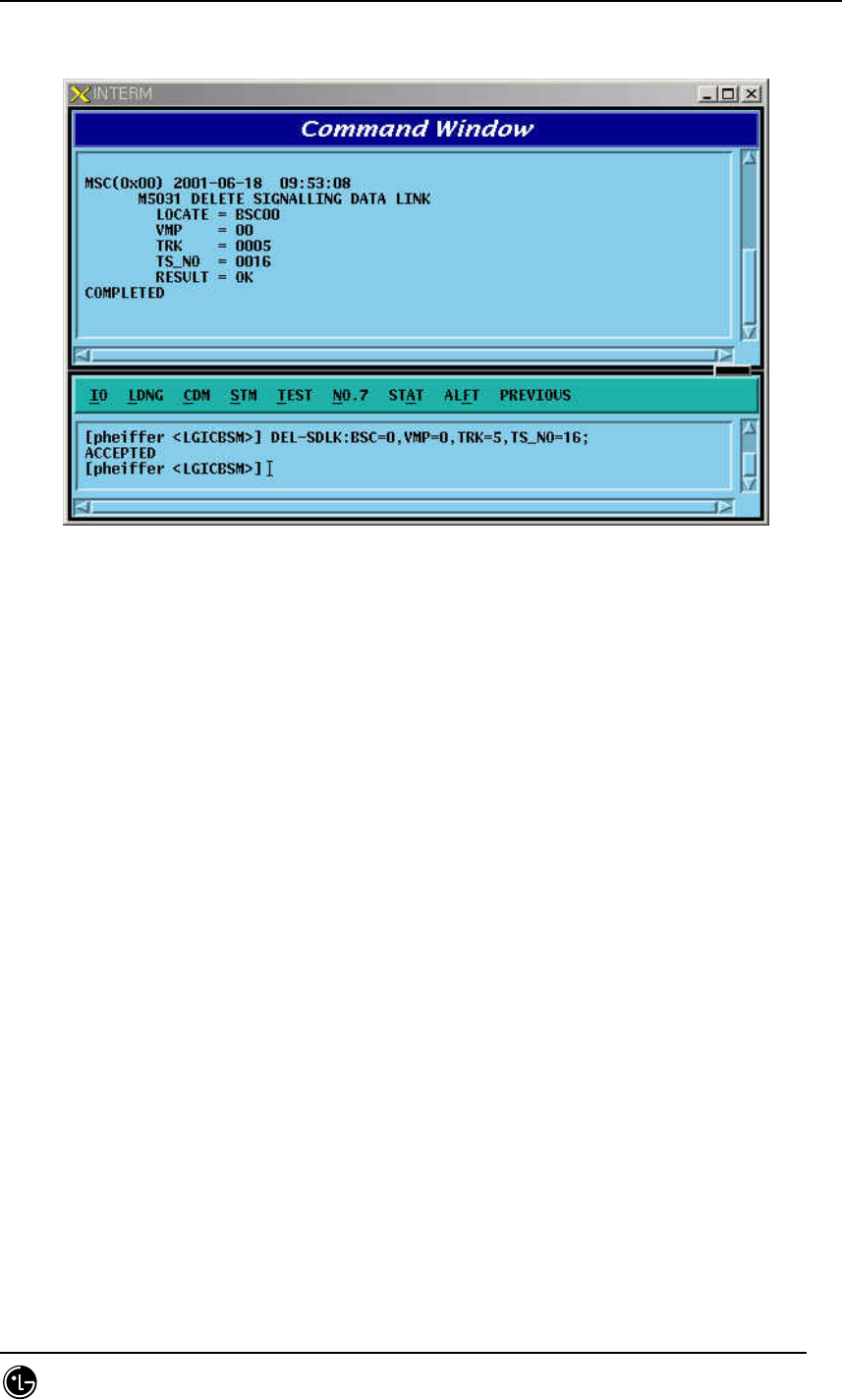
STAREX-IS BSM Manual
Page:477(877)
Issue:1.
0
SMD-011-PMA210
Input DEL-SDLK:BSC=0, VMP=0, TRK= 5, TS_NO = 16;
Output
Fig. 4.6-17 Signaling Data Link Deletion
4.6.2.18. Signaling Data Link Information Display
Function to display information on the defined Signaling Data Link and the status
connected to Signaling Link.
Command DIS-SDLK-INFO: BSC_ID = a;
a = BSC Number ( 00 ~ 11 )
Input DIS-SDLK-INFO: BSC_ID=0;
Output
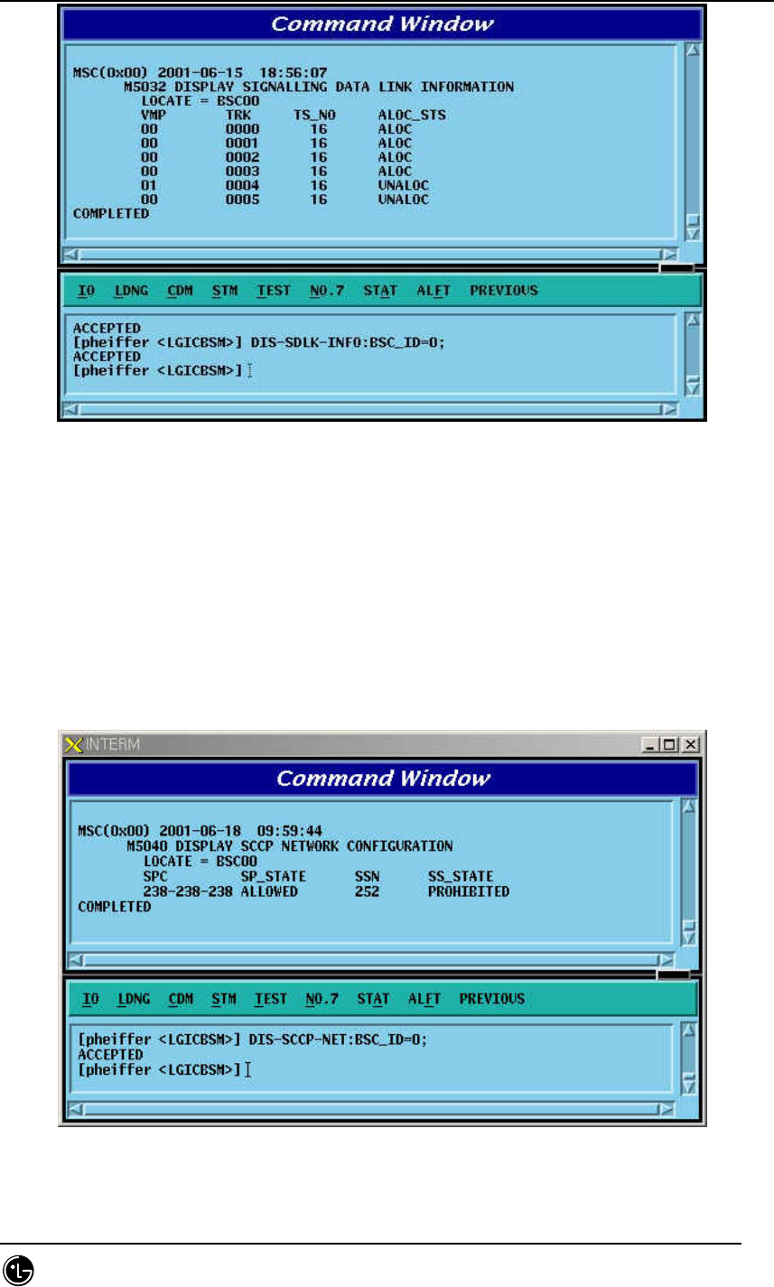
STAREX-IS BSM Manual
Page:478(877)
Issue:1.
0
SMD-011-PMA210
Fig. 4.6-18 Signaling Data Link Information Display
4.6.2.19. SCCP Network Configuration Data Display
Function to display SCCP Network Configuration Data for Intra-Switching Office
Signaling Point, local Switching Office Signaling Point, and each sub-system.
Command DIS-SCCP-NET:BSC_ID=a;
a = BSC Number ( 00 ~ 11 )
Input DIS-SCCP-NET:BSC_ID=0;
Output
Fig. 4.6-19 SCCP Network Configuration Data Display