LG Electronics USA 3G1XOUTBTS STAREX-IS 1900 Outdoor BTS User Manual STAREX IS User s Manual
LG Electronics USA STAREX-IS 1900 Outdoor BTS STAREX IS User s Manual
Contents
- 1. Users Manual Part 1
- 2. Users Manual Part 2
- 3. Users Manual Part 3
- 4. Users Manual Part 4
- 5. Users Manual Part 5
Users Manual Part 3
STAREX-IS BSM Manual
Page:479(877)
Issue:1.
0
SMD-011-PMA210
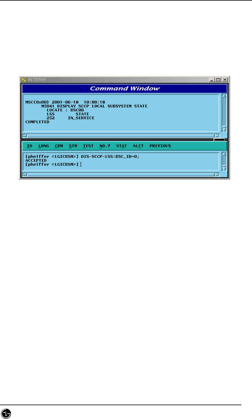
4.6.2.20. SCCP Local Subsystem State Data Display
Function to display State related to Local Exchange Sub-system defined at Local
Exchange Signaling Point
Command DIS-SCCP-LSS:BSC_ID =a;
a = BSC Number ( 00 ~ 16 )
Input DIS-SCCP-LSS:BSC_ID = 0;
Output
Fig. 4.6-20 SCCP Local Subsystem State Data Display
4.6.2.21. Signaling Link Status Display
Function to display a designated Signaling Link Status, Activate Status of Signaling
Link, Inhibit Status of Intra switching office Signaling Link, and Inhibit Status of local
Switching Office.
Command DIS-SLK-STS:BSC_ID = a, SLC = b;
a = BSC Number ( 00 ~ 11)
b = Signalling Number Code ( 00 ~ 16 )
Input DIS-SLK-STS:BSC_ID = 0, SLC=0;
Output
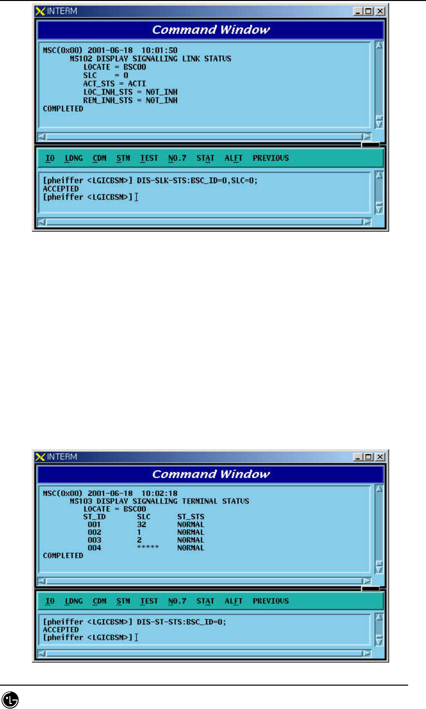
STAREX-IS BSM Manual
Page:480(877)
Issue:1.
0
SMD-011-PMA210
Fig. 4.6-21 Signaling Link Status Display
4.6.2.22. Signaling Terminal Status Display
Function to display Status Information for a specific signaling Tunnel, including
the types of data such as SLC, Trunk Number, Signaling Data Link Number, and present
Status.
Command DIS-ST-STS:BSC_ID=0;
a = BSC Number ( 00 ~ 15 )
Input DIS-ST-STS:BSC_ID=0;
Output
STAREX-IS BSM Manual
Page:481(877)
Issue:1.
0
SMD-011-PMA210
Fig. 4.6-22 Signaling Terminal Status Display
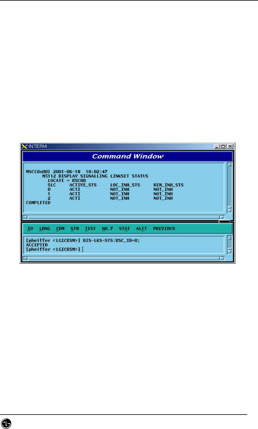
4.6.2.23. Signaling Link Set Status Display
Function to display all the Signaling Link Status connected to ASS-W to include the
status of SLC(Signaling Link Code), sl_avail(Signaling Link Availability/Non-
availability), loc_inh(Local Exchange Management Inhibit), rem_inh(Remote Management
Inhibit.
Command DIS-LKS-STS:BSC_ID=a;
a = BSC Number ( 00 ~ 11 )
Input DIS-LKS-STS:BSC_ID = 0;
Output
Fig. 4.6-23 Signaling Link Set Status Display
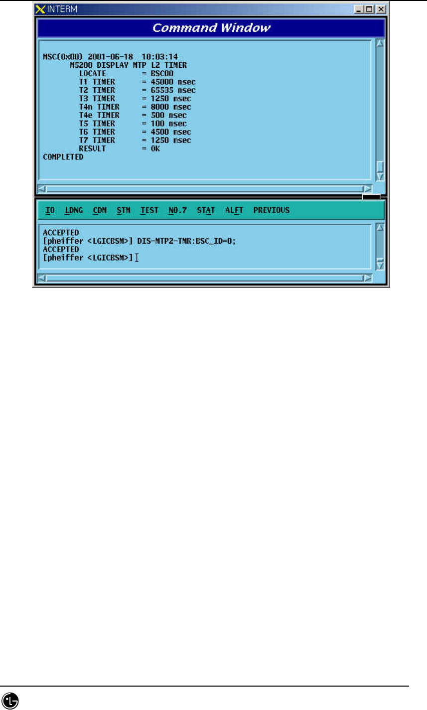
4.6.2.24. MTP Level 2 Timer Display
It displays Timer Value used for MTP L2 which is presently in operation.
Command DIS-MTP2-TMR:BSC_ID = a;
a = BSC Number ( 00 ~ 15 )
Input DIS-MTP2-TMR:BSC_ID = 0;
Output
STAREX-IS BSM Manual
Page:482(877)
Issue:1.
0
SMD-011-PMA210
Fig. 4.6-24 MTP Level2 Timer Display
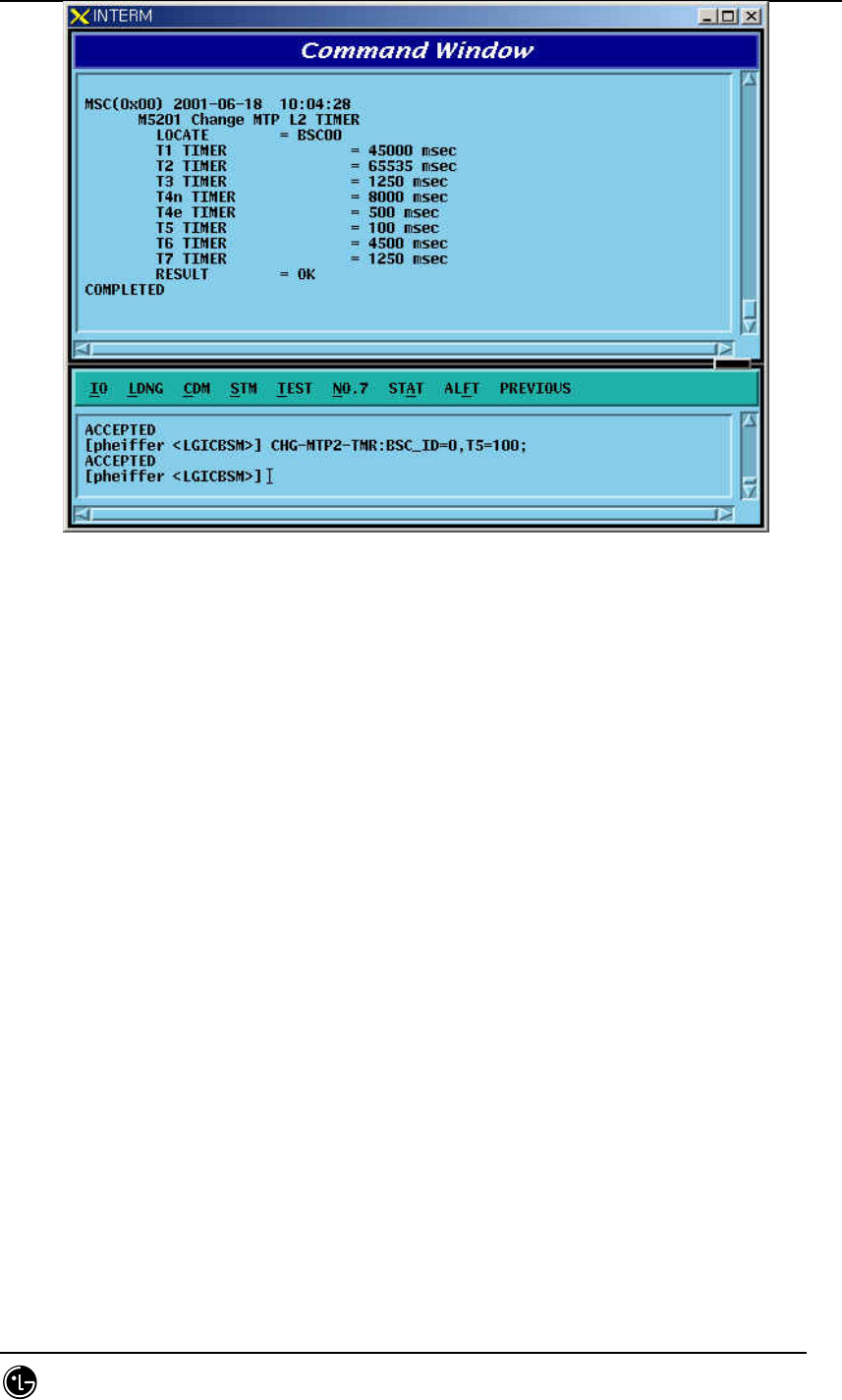
4.6.2.25. MTP Level 2 Timer Change
It changes Timer Value used for MTP L2 which is presently in operation.
Command CHG-MTP2-TMR:BSC_ID=a, T1=b, T2 =c, T3=d, T4N = e, T4E = f,
T5 =g, T6 = h, T7= i;
a = BSC Number ( 00 ~ 15 )
b = T1 Timer ( 40000 ~ 50000 )
c = T2 Timer ( 5000 ~ 150000 )
d = T3 Timer ( 1000 ~ 2000 )
e = T4N Timer ( 7500 ~ 9500 )
f = T4E Timer ( 00 ~ 600 )
g = T5 Timer ( 80 ~ 120 )
h = T6 Timer ( 3000 ~ 5000 )
I = T7 Timer ( 500 ~ 2000 )
Input CHG-MTP2-TMR:BSC_ID=0, T5 = 100;
Output
STAREX-IS BSM Manual
Page:483(877)
Issue:1.
0
SMD-011-PMA210
Fig. 4.6-25 MTP Level2 Timer Change
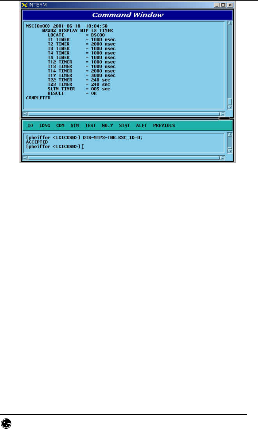
4.6.2.26. MTP Level 3 Timer Diplay
It displays Timer Value used for MTP L3 which is presently in operation.
Command DIS-MTP3-TMR:BSC_ID =a;
a = BSC Number ( 00 ~ 15 )
Input DIS-MTP3-TMR:BSC_ID = 0;
Output
STAREX-IS BSM Manual
Page:484(877)
Issue:1.
0
SMD-011-PMA210
Fig. 4.6-26 MTP Level3 Timer Display
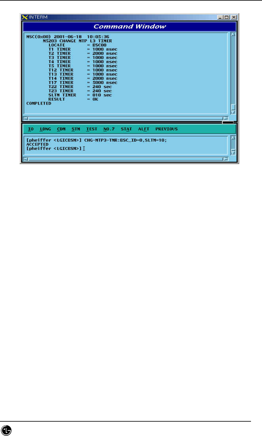
4.6.2.27. MTP Level 3 Timer Change
It changes Timer Value used for MTP L3 which is presently in operation.
Command CHG-MTP3-TMR:BSC_ID = a, T1 = b, T2 = c, T3 = d, T4 = e, T5 =
f, T12 = g, T13= h, T14 = i, T17 = j, T22 = k, T23 = l, SLTM = m;
a = BSC Number ( 00 ~ 11 )
b = T1 Timer ( 500 ~ 1200 )
c = T2 Timer ( 700 ~ 2000 )
d = T3 Timer ( 500 ~ 1200 )
e = T4 Timer ( 500 ~ 1200 )
f = T5 Timer ( 500 ~ 1200 )
g = T12 Timer ( 800 ~ 1500 )
h = T13 Timer ( 800 ~ 1500 )
I = T14 Timer ( 2000 ~ 3000 )
j = T17 Timer ( 800 ~ 5000 )
l = T22 Timer ( 180 ~ 360 )
l = T23 Timer ( 180 ~ 360 )
m = SLTM Timer ( 4 ~ 12 )
Input CHG-MTP3-TIMER:BSC_ID=0, SLTM=10;
STAREX-IS BSM Manual
Page:485(877)
Issue:1.
0
SMD-011-PMA210
Output
Fig. 4.6-27 MTP Level e 3 Timer Change
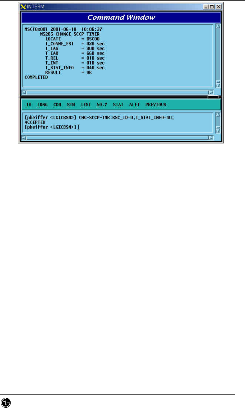
4.6.2.28. SCCP Timer Display
It changes Timer Value used for SCCP which is presently in operation.
Command CHG-SCCP-TMR:BSC_ID=a, T_CONNE_EST = b, T_IAS = c, T_IAR =
d, T_REL = e, T_INT =f , T_STAT_INFO = g;
a = BSC Number ( 00 ~ 11 )
b = T_CONNE_EST ( 20 ~ 120 )
c = T_IAS ( 300 ~ 600 )
d = T_IAR ( 660 ~ 1320 )
e = T_REL ( 1 ~ 20 )
f = T_INT ( 10 – 60)
g = T_STAT_INFO ( 5 ~ 1200 )
Input CHG-SCCP-TMR:BSC_ID=0, T_STAT_INFO=40;
Output
STAREX-IS BSM Manual
Page:486(877)
Issue:1.
0
SMD-011-PMA210
Fig. 4.6-28 SCCP Timer Change
4.6.3. Maintenance Function Command
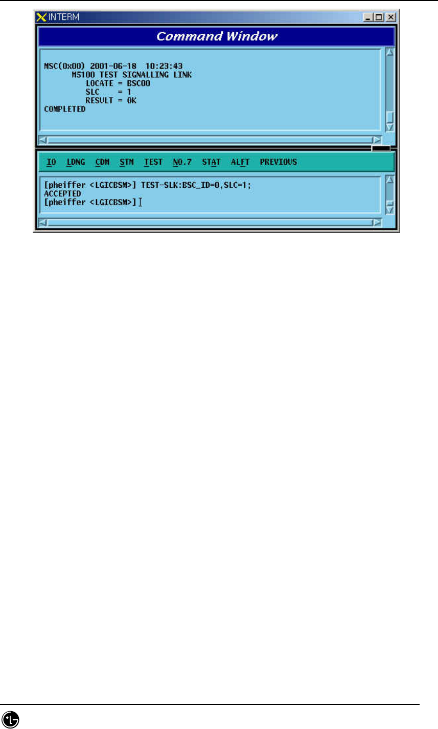
4.6.3.1. Signaling Link Test
Signaling Link Test is performed while Signaling Link is in service when Signaling Link
becomes activated or restored and is used to check if both ends of Signaling Link
process messages correctly. The status of Signaling Link to be tested should be in the
Activate Status.
Command TEST-SLK:BSC_ID=a, SLC =b;
a = BSC Number ( 0 ~ 11 )
b = Signalling Link Code ( 0 ~ 15 )
Input TEST-SLK:BSC_ID= 0, SLC = 1;
Output
STAREX-IS BSM Manual
Page:487(877)
Issue:1.
0
SMD-011-PMA210
Fig. 4.6-29 Signaling Link Test
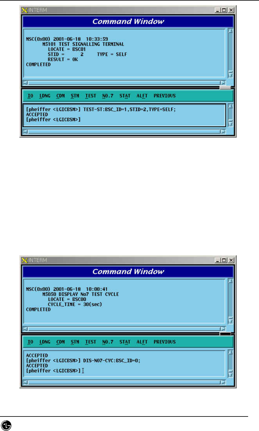
4.6.3.2. Signaling Terminal Test
Signaling Terminal Test consists of RA Loopback and SELF Loopback, and RA
Loopback performs Loopback in Rate Adaptation function, performing an activation of
Signaling Link. Depending upon the result, it performs inspection function on the
Signaling Terminal and Lookback performs Lookback to STPA receiving terminal,
providing inspection function of Status. A test should be successfully conductedto
Signaling Terminal where corresponding Signaling Terminal is not allocated to
Signaling Link before testing Signaling Terminal, so that normal test result can be
reported.
Command TEST-ST:BSC_ID=a, STID =b, TYPE=c;
a = BSC Number ( 00 ~ 11 )
b = Signalling Terminal ( 1 ~ 16 )
c = TYPE ( SELF, RA )
Input TEST-ST:BSC_ID = 1, STID =2, TYPE=SELF;
Output
STAREX-IS BSM Manual
Page:488(877)
Issue:1.
0
SMD-011-PMA210
Fig. 4.6-30 Signaling Terminal Test
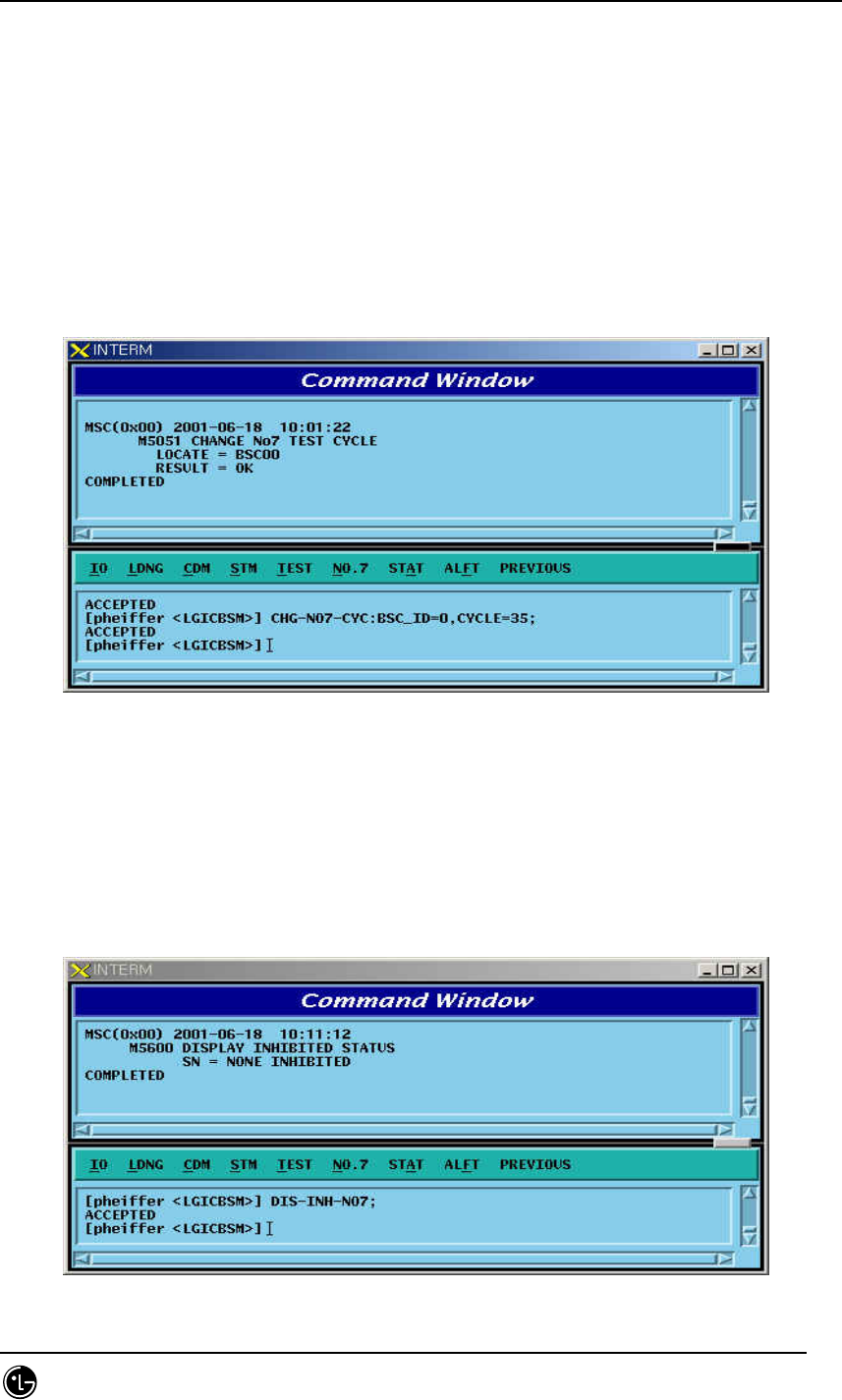
4.6.3.3. Test Cycle Display
Signaling Terminal Automatic Test is not a test on the request from the operator to
Signaling Terminal allocated to Signaling Link, but the test is performed on Signaling
Terminal by the Processor cyclically, which displays Test Cycle (default: 30sec) .
Command DIS-NO7-CYC:BSC_ID=a;
a = BSC Number ( 00 ~ 11 )
Input DIS-NO7-CYC:BSC_ID = 0;
Output
Fig. 4.6-31 Test Cycle Display
STAREX-IS BSM Manual
Page:489(877)
Issue:1.
0
SMD-011-PMA210
4.6.3.4. Test Cycle Change
It is used to change Test Cycle which is performed by Processor (SCP).
Command CHG- NO7-CYC:BSC_ID=a, CYC=b;
a = BSC Number ( 00 ~ 11 )
b = Cycle ( 00 ~ 120 )
Input CHG-NO7-CYC:BSC_ID=0, CYC=35;
Display
Fig. 4.6-32 Test Cycle Change
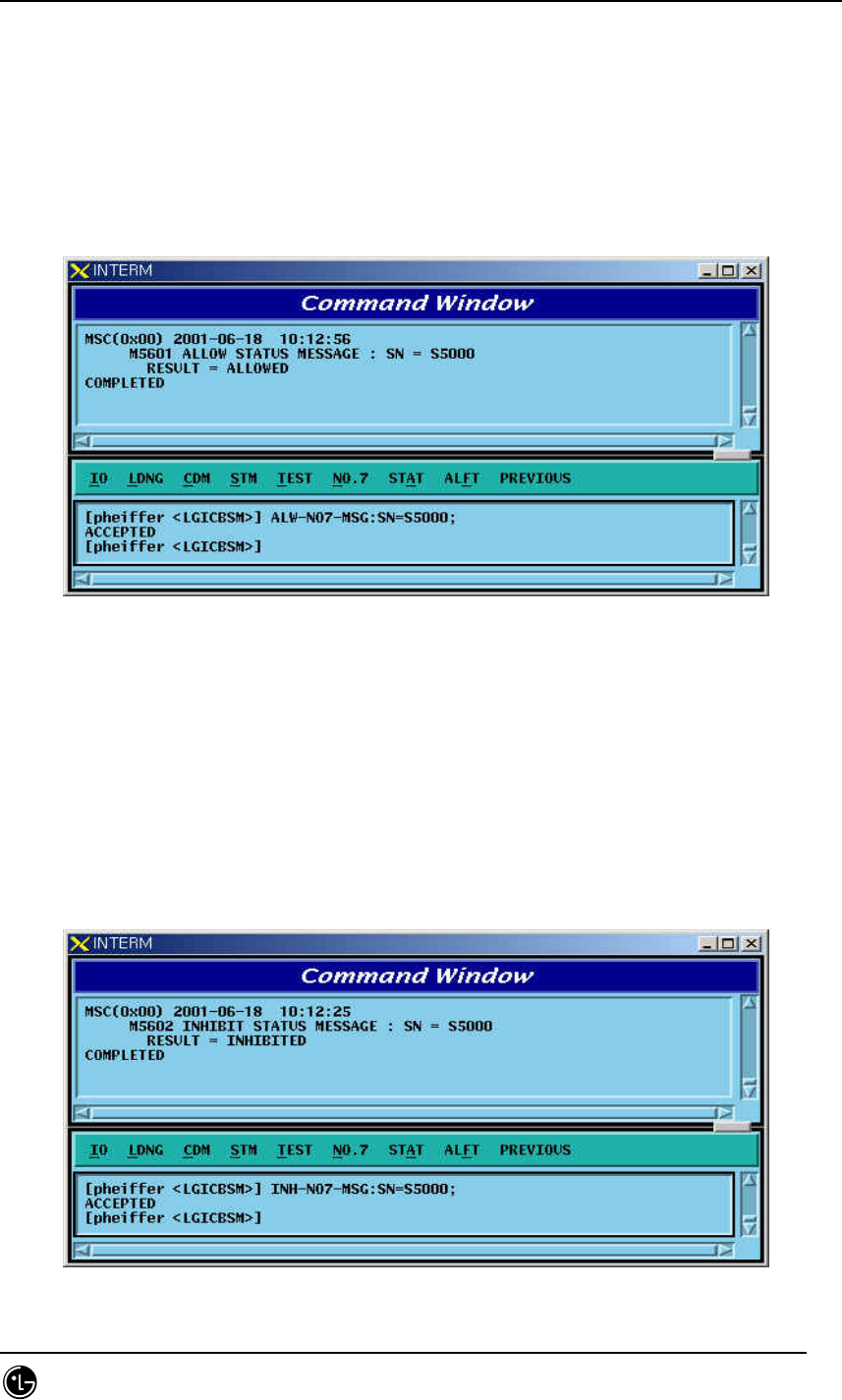
4.6.3.5. Inhibited Status Message Display
It displays Status Message that can be displayed at present.
Command DIS-INH-NO7;
Input DIS-INH-NO7;
Output
Fig. 4.6-33 Output possible Status Message Display
STAREX-IS BSM Manual
Page:490(877)
Issue:1.
0
SMD-011-PMA210
4.6.3.6. Status Message Display Allow
It allows to display Status Message on Outterm.
Command ALW-NO7-MSG:SN=a;
a = Status Number ( ALL, S5000, S5001, S5010, S5011, S5012, S5013, S5020,
S5021, S5022, S5023, S0524, S5025, S5026, S5027, S5028, S5030, S5031, S5032 )
Input ALW-NO7-MSG:SN=S5000;
Output
Fig. 4.6-34 Status Message Display Allowed
4.6.3.7. Status Message Display Inhibit
It inhibits to display Status Message on Outterm
Command INH-NO7-MSG:SN= a
a = Status Number ( ALL, S5000, S5001, S5010, S5011, S5012, S5013, S5020,
S5021, S5022, S5023, S0524, S5025, S5026, S5027, S5028, S5030, S5031, S5032 )
Input INH-NO7-MSG:SN=S5000;
Output
Fig. 4.6-35 Status Message Display Inhibit

STAREX-IS BSM Manual
Page:491(877)
Issue:1.
0
SMD-011-PMA210
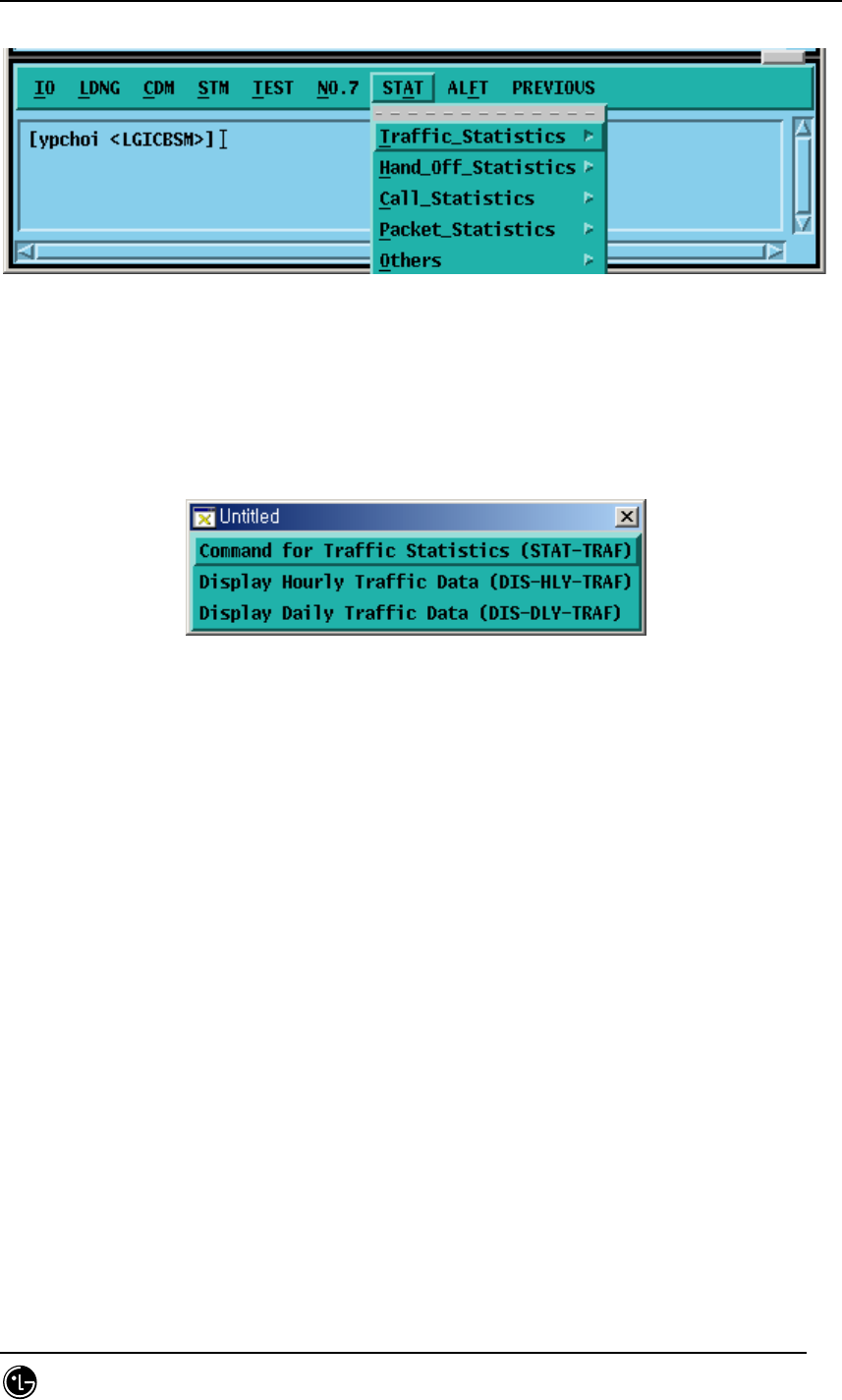
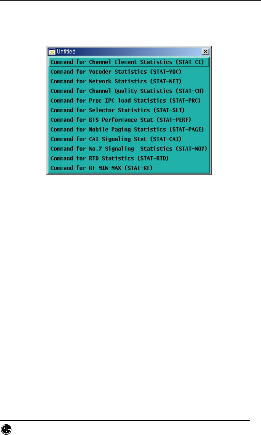
4.7. Statistics Command
Apart from switching system, statistics Function in BSM measures performance and
load and reports them to NMS(Network Management System), a center for self-
reporting and network management. The function of statistics is divided logistically
into three. The first one is that On Demand statistics items that the user measures
designated statistics item and BTS on the arbitrary time for the specific cycles.
And additionally to be included is Hourly Statistic that collects, without complying with
the user’s request, all the statistics always on time for reporting to NMS. Lastly, it is
divided into On Line Statistics that collects and sends statistics every 5 minutes so
that NMS can confirm on a real time basis. The following commands in series are
mainly related to On Demand Statistics, and Hourly Statistics function was configured,
in consideration of BMS performance to display on request only from user.
On Demand Statistics function is used only when the user wants to check performance
related data with specific BSC or BTS. For Hourly Statistics function, once statistics
report is requestedto CCP, BSP, PCP, NCP and CNP that are major processors at
every fixed time, all kinds of statistics collected are gathered at the corresponding
processor and transferred. Section between BSM and BSS are connected to STM-1,
but because the volumes of the collected statistics are so huge that they are executed
for 15 minutes.
That is, the report of statistics data to NMS is made at 15 minutes after the every hour.
BSM becomes to keep hourly statistics data. Storages are made on an hourly basis for
a week and are stored in binary in PKG/DATA/STAT/HOURLY. Reports to NMS are
made by the reporting method of ASCII and the method providing Binary and Library at
the user’s request.
Table 4.7-1 Statistics Command List
Division Content Statistics Commands
Traffic STAT-TRAF:DIR=a,OPTION=b,BSC=c,BTS=d
[,MPRD=e, MTIM=f];
Hourly Traffic DIS-HLY-TRAF:HOUR=a,OPTION=b,BSC=c,BTS=d;
Traffic
Related
Daily Traffic DIS-DLY-TRAF:WEEK=a,HOUR=b,OPTION=c,BSC=d,BTS=e;
Hand off (all) STAT-HOFF:BSC=a,BTS=b[,MPRD=c, MTIM=d]; Hand off
Related Softer Handoff STAT-HOFF-SOFTER:BSC=a[,BTS=b,MPRD=c, MTIM=d];

STAREX-IS BSM Manual
Page:492(877)
Issue:1.
0
SMD-011-PMA210
Soft Handoff STAT-HOFF-SOFT:BSC=a[,BTS=b,MPRD=c, MTIM=d];
Hard Handoff STAT-HOFF-HARD:BSC=a[,BTS=b,MPRD=c, MTIM=d];
Channel Element STAT-CE:BSC=a[,BTS=b,MPRD=c, MTIM=d];
Vocoder STAT-VOC:BSC=a,VMP=b[,VCP=c,MPRD=d, MTIM=e];
Network
STAT-
NET:CAN=a,BSC=b[,BTS=c,ITEM=d,MPRD=d,MTIM=e];
Radio Channel STAT-CH:BSC=a[,BTS=b,MPRD=c,MTIM=e];
Processor STAT-PRC:CAN=a,BSC=b[,BTS=c,MPRD=d,MTIM=e];
Selector STAT-SLT:BSC=a,SMP=b[,SLP=c,MPRD=d,MTIM=e];
BTS Performance STAT-PERF:BSC=a[,BTS=b,MPRD=c,MTIM=d];
Paging STAT-PAGE:BSC=a[,BTS=b,MPRD=c,MTIM=d];
CAI Signaling STAT-CAI:ITEM=a,BSC=b[,BTS=c,MPRD=d, MTIM=e];
NO7 STAT-NO7:ITEM=a,SCP=b[,MPRD=c,MTIM=d];
Round Trip Delay STAT-RTD:BSC=a,BTS=b[,MPRD=c,MTIM=d];
Call Related
RF Min/Max STAT-RF:BSC=a,BTS=b,ITEM=c[,MPRD=d,MTIM=e];
Packet Data STAT-PKD:PCP=a,SHELF=b[,PIP=c,MPRD=d,MTIM=e];
Packet Control STAT-PKC:PCP=a[,MPRD=b, MTIM=c];
Packet
Related
Packet Handoff STAT-PCP:PCP=a[,MPRD=b, MTIM=c];
Statistic List DIS-STAT-ITEM;
Statistics Job DIS-STAT-JOB;
Statistics Stop CAN-STAT:[BSC=a,]JOB=b;
Hourly Statistic
Display
DIS-HLY-DATA:HOUR=a,ITEM=b,BSC=c[,BTS=d];
Daily Statistics
Display
DIS-DLY-DATA:WEEK=a,HOUR=b,ITEM=c,BSC=d[,BTS=e];
Others
Online Cycle
Change
CHG=ONLINE-MPRD[:MPRD=a];
Display of Hourly/Daily Statistics for the same item of statistics is identical to On
Demand Statistics. It is not related to Processor or Device that measures and reports
statistics, but is related only to equip of PLD.
This function of statistics is consisted of 5 Categories to include Traffic, Handoff, Call
related, Packet related and others, and in the window of user’s command the following
is displayed.
STAREX-IS BSM Manual
Page:493(877)
Issue:1.
0
SMD-011-PMA210
Fig. 4.7-1 Configuration of Statistics Command
4.7.1. Traffic related Statistics Command
Traffic Statistics is differentiated as follows:
Fig. 4.7-2 Traffic Statistics Function
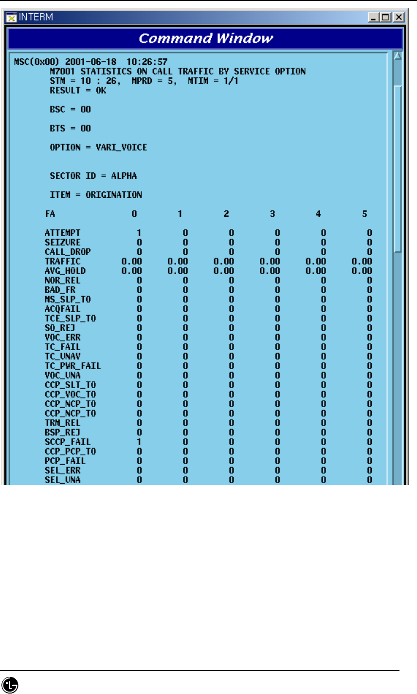
4.7.1.1. Traffic Statistics by Service Option
This is a function which for originating call and terminating call, reports and displays
the number of attempt by service option, number of success, number of failure and the
collected content by reason of a failure by CCP to BSM, and for Statistics Data,
collection is made by the separated each item of Service Option/Direction/
BSC/BTS/FA/SECTOR..
Command : STAT-TRAF:DIR=a,OPTION=b,BSC=c,BTS=d[,MPRD=e,MTIM=f];
a : DIR : ALL – Measuring all of originating calls and terminating calls
ORG – Measuring originating only
TRM – Measuring terminating call only
b: OPTION :
VOICE 8K voice
VARI_VOICE 8K EVRC
ASYNC Asynchronous Data(9.6 kbps)
G3FAX Group 3 FAX(9.6 Kbps)
SMS Short Message Service

STAREX-IS BSM Manual
Page:494(877)
Issue:1.
0
SMD-011-PMA210
PPP_PKT Packet Data
ASYNC_13K Asynchronous Data(14.4 kbps)
G3FAX_13K Group 3 FAX(14.4 kbps)
SMS_13K Short Message(Rate Set 2)
PPP_PKT_13K Packet Data 13kbps
VOICE_13K 13K voice (IS-96)
PKT_TYPE1_22 High Speed Packet Data Services
PKT_TYPE2_25 High Speed Packet Data Services
PACKET_144K 144kbsps Packet Data
c: BSC : BSC number ( 0 ~ 11 )
d: BTS : BTS number ( 0 ~ 47 )
e: MPRD : Cycle (min) ( default : 30min )
f : MTIM : Repeat frequency(default : 4times )
Display result
STAREX-IS BSM Manual
Page:495(877)
Issue:1.
0
SMD-011-PMA210
Fig. 4.7-3 Traffic Statistics Data Display Result
(*) Reference to Appendix for description of each item in the above Fig..
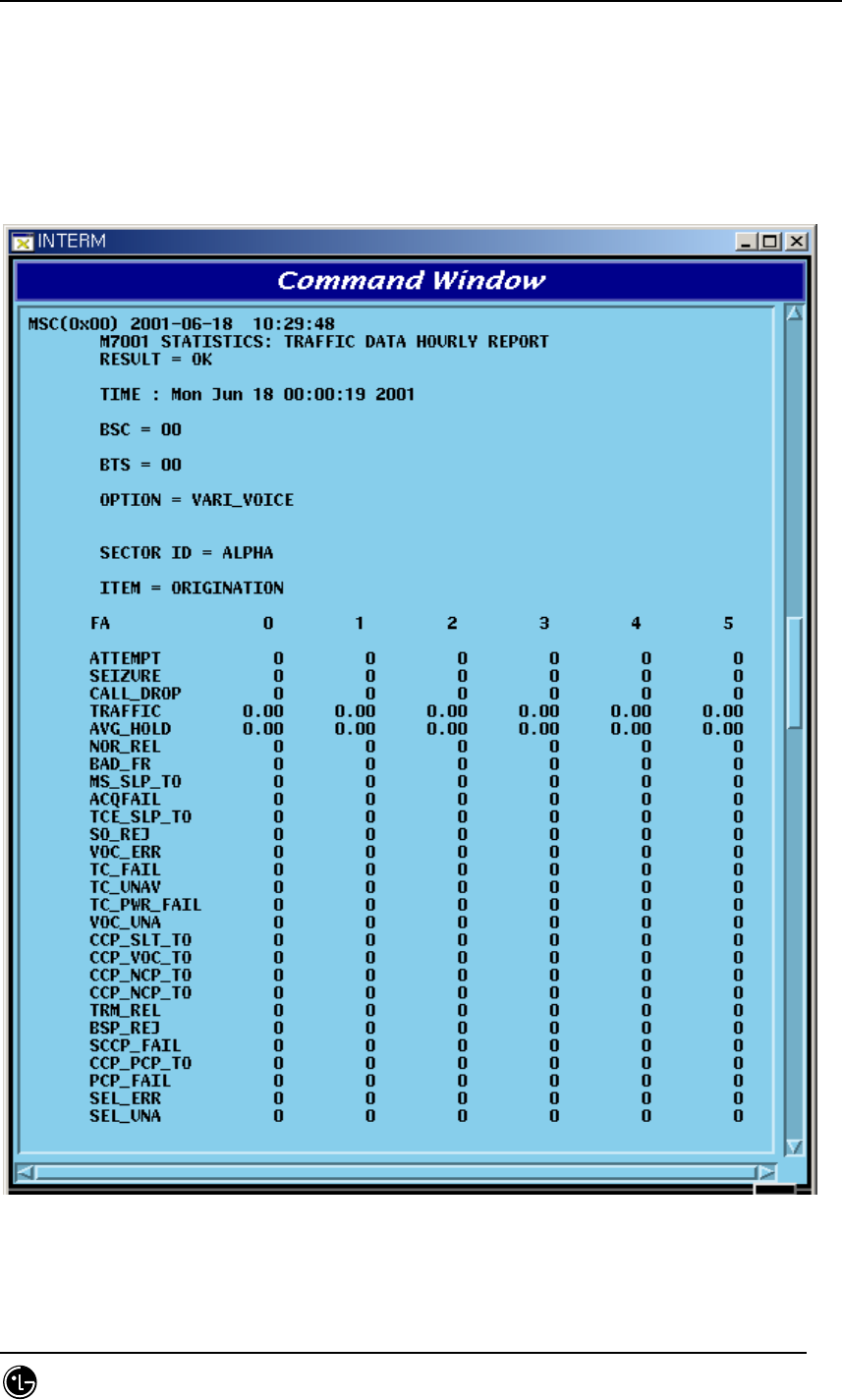
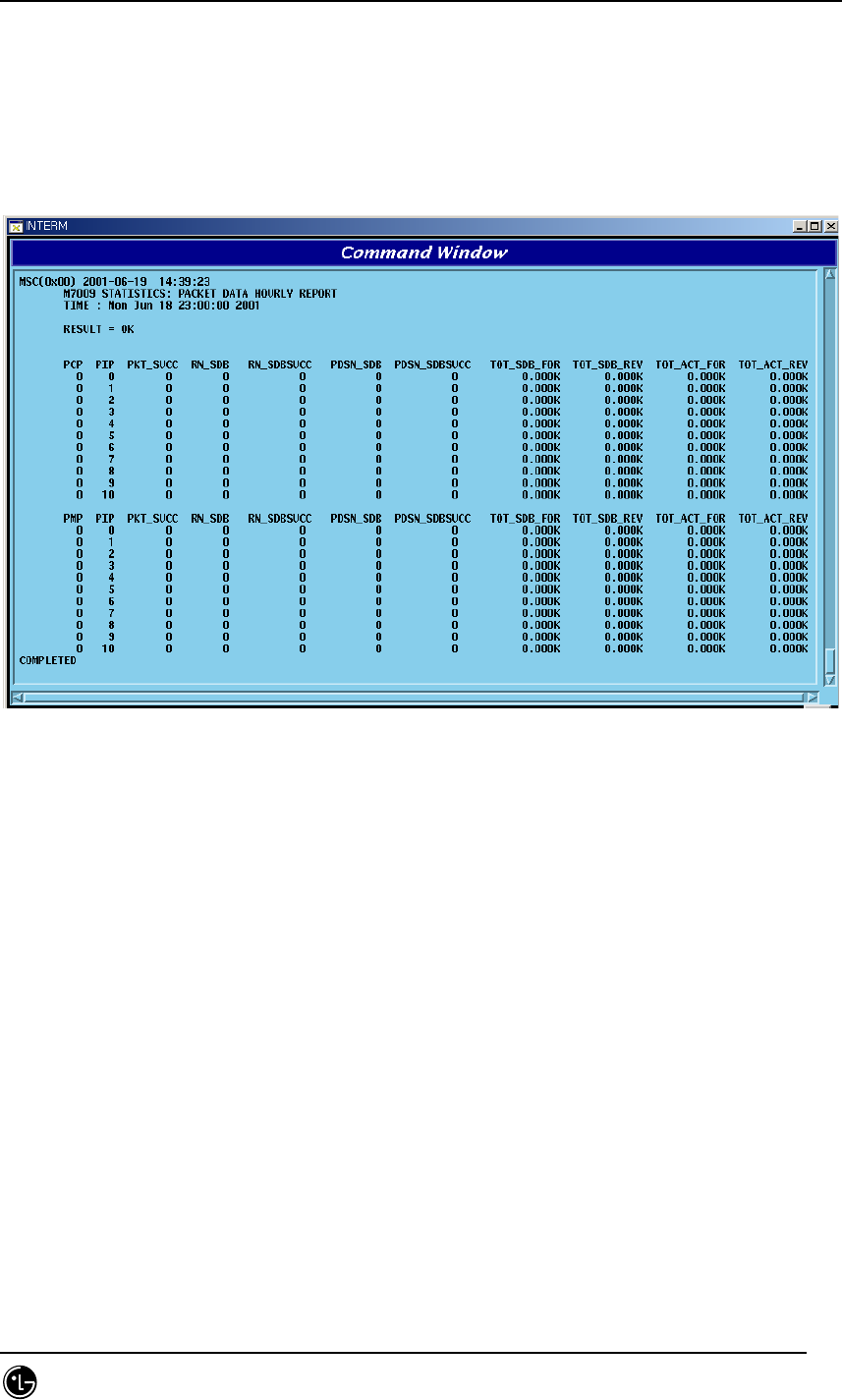
4.7.1.2. Hourly Traffic Statistic DISPLAY
Function that inquires about the traffic statistics collected on hourly basis by BSC,
BTS and service option by every hour.
STAREX-IS BSM Manual
Page:496(877)
Issue:1.
0
SMD-011-PMA210
Command : DIS-HLY-TRAF:HOUR=a, OPTION=b, BSC=c, BTS=d;
a: HOUR : Time
b: OPTION : Service option
c: BSC : BSC number
d : BTS : BTS number
Fig. 4.7-4 Hourly Traffic Statistics Display Result
(*)Reference made to Annex for description of each item in the above Figure
STAREX-IS BSM Manual
Page:497(877)
Issue:1.
0
SMD-011-PMA210
4.7.1.3. Daily Traffic Statistic DISPLAY
Function that inquires about the Hourly Traffic Statistics collected in a week by BSC
by hour, by BTS and by service option.
Command : DIS-DLY-TRAF:WEEK=a,HOUR=b, OPTION=c, BSC=d, BTS=e;
a. WEEK : Day of the Week (MON/TUE/WED/THU/FRI/SAT/SUN)
b: HOUR : Time (24hour system)
c: OPTION : Service Option
d: BSC : BSC number (0 ~ 11)
e : BTS : BTS number (0 ~ 47)
Display : Result is same as the content of 4.6.1.2.
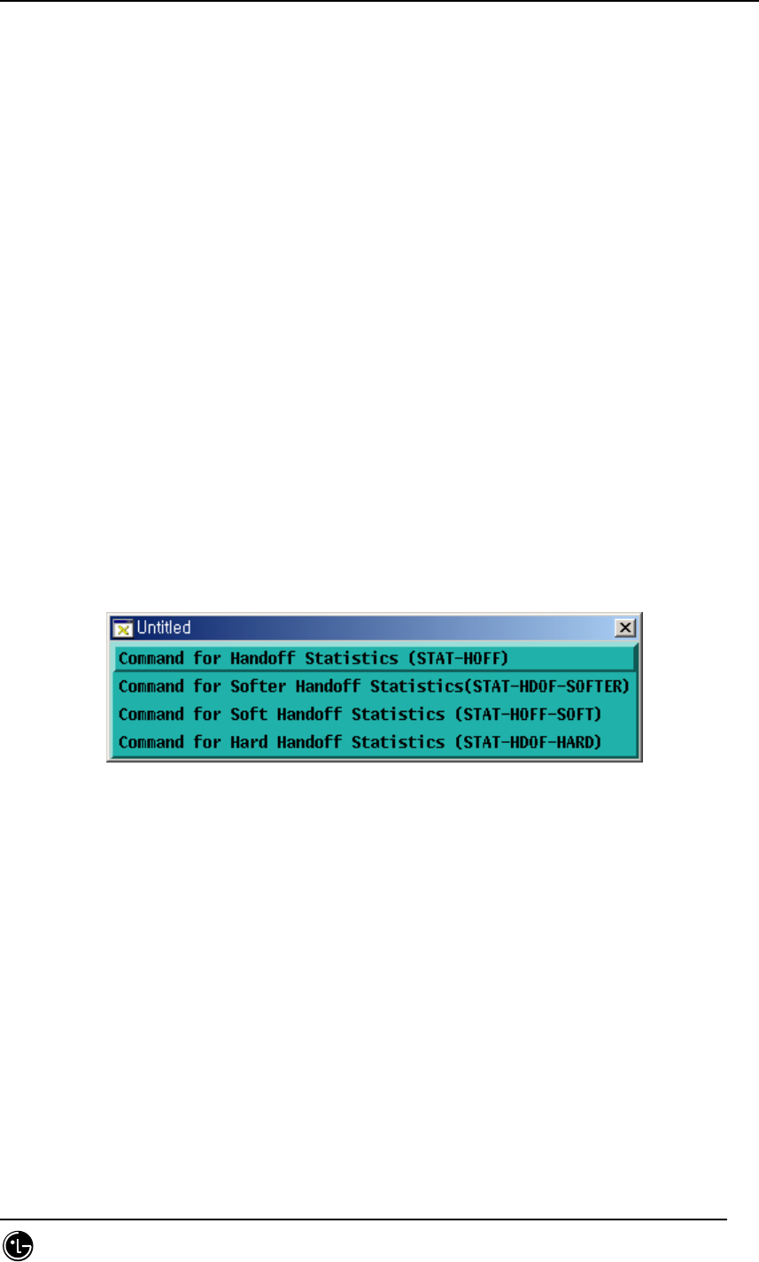
4.7.2. Handoff Related Statistics Function
Handoff Statistics function appears as follows:.
Fig. 4.7-5 Handoff related Statistics Function
4.7.2.1. Handoff Statistics
Function that CCP conducts measurement of Handoffs generated in each BSC in
reference to the kind of Handoff(softer, soft, hard) and its direction and then reports to
BSM. Handoffs are divided into the kinds as follows:
Softer Handoff
Softer Handoff generated between sectors in the same BTS
Soft Hand off
- Intra BTS soft Handoff : Soft Handoff generated between sectors in the same Base

STAREX-IS BSM Manual
Page:498(877)
Issue:1.
0
SMD-011-PMA210
Station
- Intra BSC Soft Handoff : Soft Handoff generated between the same BSCs
- Inter MSC Soft Handoff : Soft Handoff generated between other BSCs
Hard Hand off
- Intra Cell Hard Handoff : Hard Handoff generated by frequency change in the same
BTS
- Intra BSC FR Hard Handoff : Hard Handoff generated by frequency change between
BTSs of the same BSC
- Intra BSC FO Hard Handoff : Hard Handoff generated by Frame offset between
BTSs of the same BSC
- Inter BSC FR Hard Handoff : Hard Handoff by frequency change generated between
BTSs of other BSCs
- Inter BSC FO Hard Handoff : Hard Handoff by the change of Frame offset generated
between BTSs of other BSCs
- Hard Hand off between RCs : Handoff generated between RCs
Command : STAT-HOFFF:BSC=a, BTS=b[,MPRD=c,MTIM=d];
a : BSC : BSC number ( 0 ~ 11)
b : BTS : BTS number ( 0 ~ 47 )
c : Cycle(minute) : Default 30min
d : Repetition Frequency : Default 4 times
Display :
STAREX-IS BSM Manual
Page:499(877)
Issue:1.
0
SMD-011-PMA210
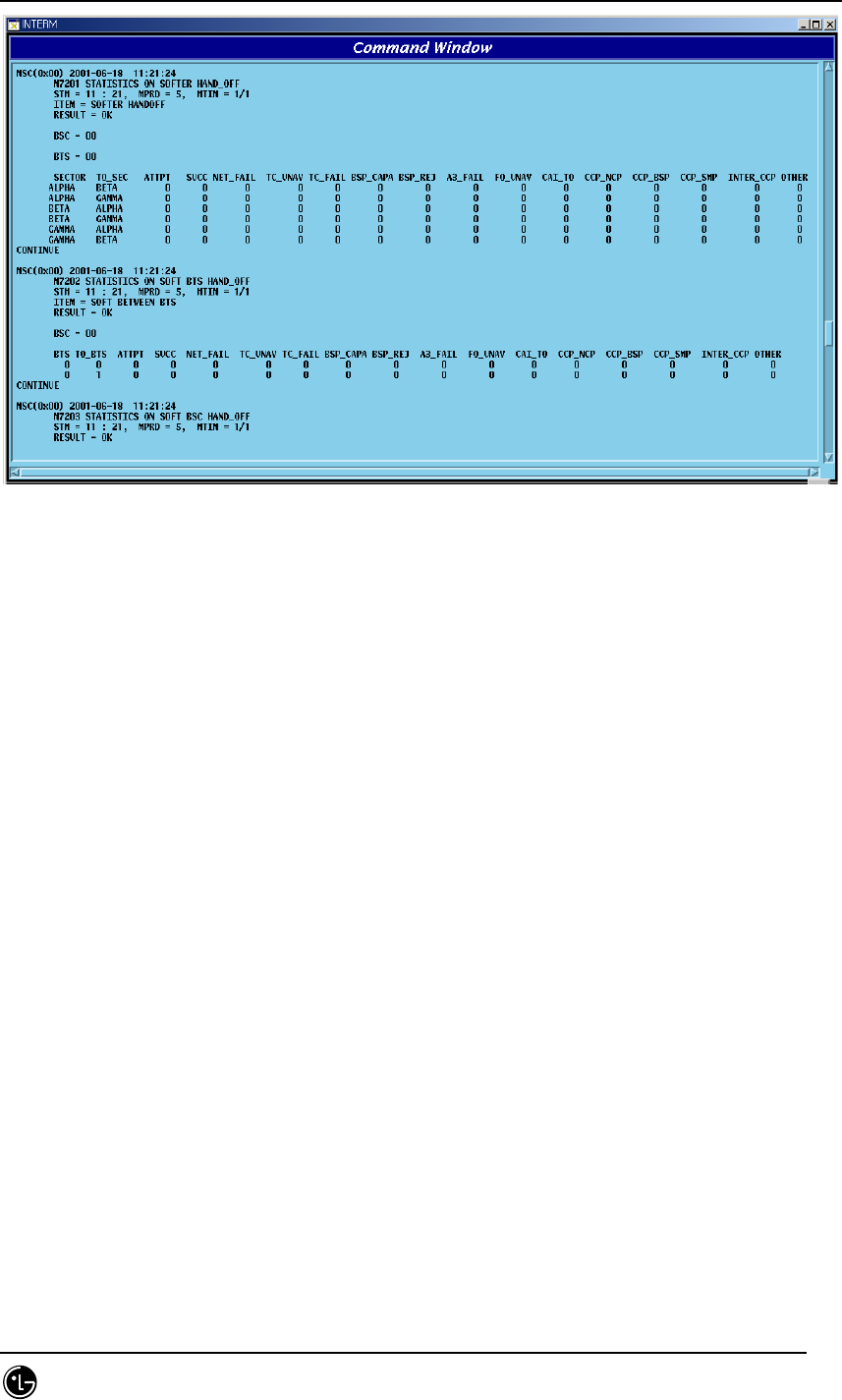
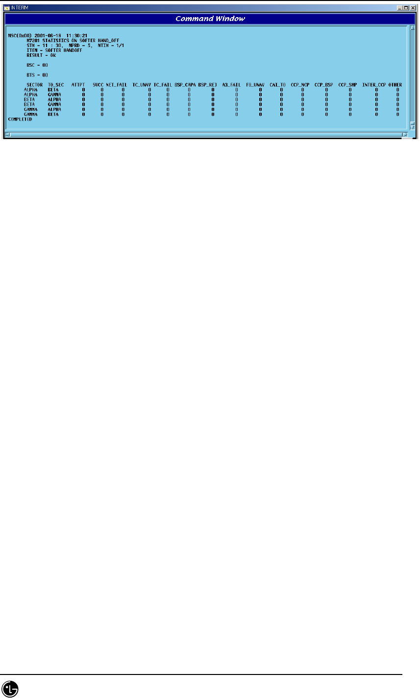
Fig. 4.7-6 Handoff Statistics
(*)This Command(STAT-HOFF) displays all kinds of Handoff. Refer to Appendix for
each item.
4.7.2.2. Softer Handoff Statistics
It collects by collected item (refer to Appendix) the soft Handoff generated between
sectors in the same BTS and displays.
Command : STAT-HOFF-SOFTER:BSC=a, BTS=b[,MPRD=d, MTIM=d];
a : BSC : BSC number ( 0 ~ 11)
b : BTS : BTS number ( 0 ~ 47 )
c : MPRD : Cycle(min) : Default 30min
d : MTIM : Repetition number : Default 4times
Display
STAREX-IS BSM Manual
Page:500(877)
Issue:1.
0
SMD-011-PMA210
Fig. 4.7-7 Softer Handoff Statistics Display
(*)Refer to Appendix for each item described above.
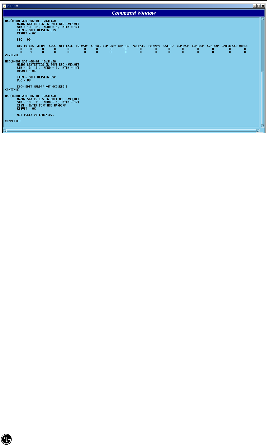
4.7.2.3. Soft Handoff Statistics
It measures for display the soft Handoff generated between sectors of the same BTS,
in the internal part of the same BSC, or in other BSC.
Command : STAT-HOFF-SOFT:BSC=a[,BTS=b, MPRD=c, MTIM=d];
a : BSC : BSC number ( 0 ~ 11 )
b : BTS : BTS number ( 0 ~ 47 )
c : Cycle(min) : Default 30min
d : Repetition Frequency : Default 4times
Display
STAREX-IS BSM Manual
Page:501(877)
Issue:1.
0
SMD-011-PMA210
Fig. 4.7-8 Soft Handoff Display Result
(*) Refer to Appendix for description of the items above.
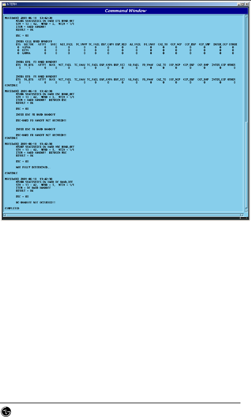
4.7.2.4. Hard Handoff Statistics
It is statistics to be measured in CCP for Hard Handoff between BSCs, such as Handoff
followed by frequency change between the same BTSs and Handoff generated in the
same BSC, and Hard Handoff generated between RCs.
Command : STAT-HOFF-HARD:BSC=a,BTS=b[,MPRD=c,MTIM=d];
a : BSC : BSC ( 0 ~ 11 )
b : BTS : BTS ( 0 ~ 47 )
c : MPRD : Cycle(min) : Default 30min
d : MTIM : Number of Frequency : Default 4times
STAREX-IS BSM Manual
Page:502(877)
Issue:1.
0
SMD-011-PMA210
Fig. 4.7-9 Hard Handoff Statistics Display
(*)Refer to Appendix for description of the each item described above.
STAREX-IS BSM Manual
Page:503(877)
Issue:1.
0
SMD-011-PMA210
4.7.3. Call Related Statistics Function
Statistics function related to call is as followed.
Fig. 4.7-10 Statistics Function Related to Call
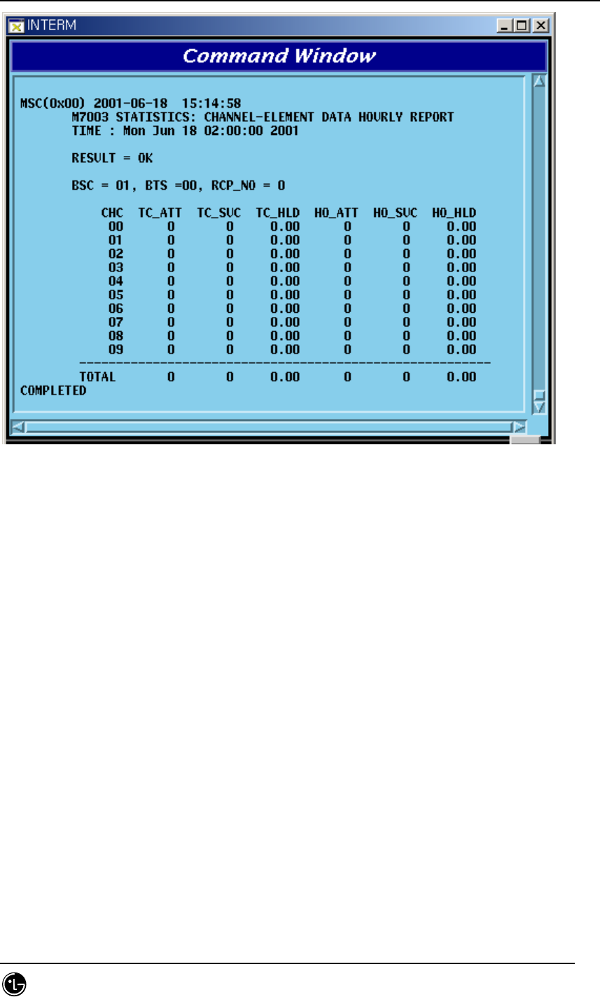
4.7.3.1. Channel Element Statistics Function
The system reports the used counts that the traffic channel is occupied by the traffic
element for the call to the BSM by BSP and channel card.
Command : STAT-CE:BSC=a[,BTS=b,MPRD=c,MTIM=d];
a : BSC : BSC number ( 0 ~ 11 )
b : BTS : BTS number ( 0 ~ 47 )
c : MPRD : Cycle(min) : Default 30min
d : MTIM : Repeat Count : Default 4times
Display.
STAREX-IS BSM Manual
Page:504(877)
Issue:1.
0
SMD-011-PMA210
Fig. 4.7-11 Channel Statistics Function
(*)Refer to the appendix for the description of each items in the figure above.
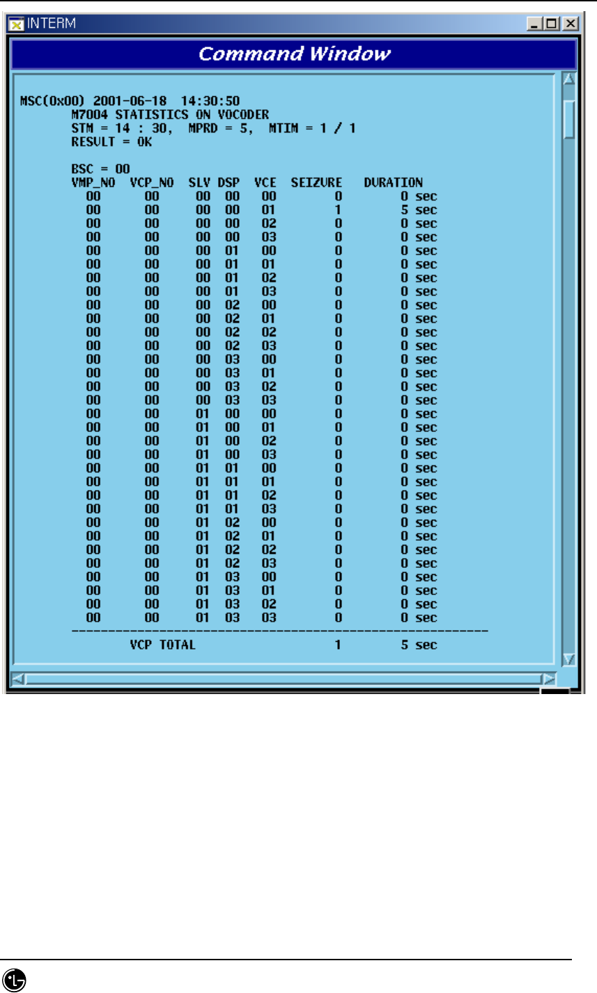
4.7.3.2. Vocoder Statistics Function
It is the function that measures and reports the occupancy count and time to vocoder
which decodes/encodes voice corresponded to channel element by 1:1. The data is
collected in VCP by VCE.
Command : STAT-VOC:BSC=a,VMP=b[,VCP=c,MPRd=d,MTIM=e];
a : BSC : BSC number ( 0 ~ 11)
b : BTS : BTS number ( 0 ~ 47)
c : VMP : Vocoder Master Processor number(0 ~ 7)
d : VCP : VCP number ( 0 ~ 15 )
e : MPRD : Cycle(min) : Default 30min
f : MTIM : Repeat Count : Default 4times
Display
STAREX-IS BSM Manual
Page:505(877)
Issue:1.
0
SMD-011-PMA210
Fig. 4.7-12 Vocoder Statistics Output
(*)Refer to the appendix for the description of each item in the figure above.
4.7.3.3. Network Statistics Function
VLIA measures and reports the use rate and error rate of T1 (or E1)’s trunk between
BSC and the switching system. ASIA and ASCA collect and report the port statistics
between BSC and CAN. LICA and ALPA are the function collecting link statistics to
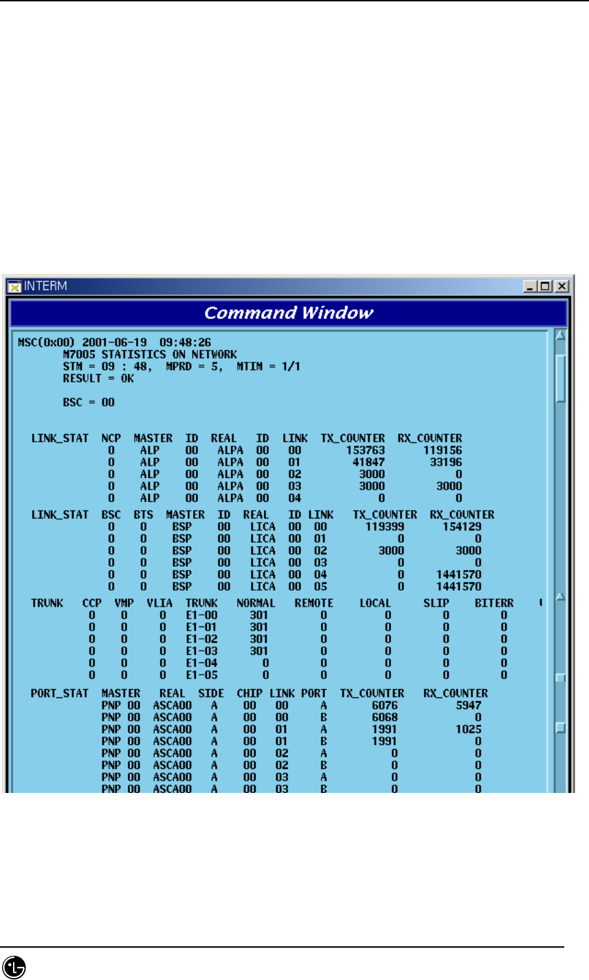
STAREX-IS BSM Manual
Page:506(877)
Issue:1.
0
SMD-011-PMA210
report between BSC and BTS.
Command : STAT-NET:CAN=a,BSC=b[,BTS=c,ITEM=d,MPRD=e,MTIM=f];
a : CAN : the participation matter of the CAN equipment processor
b : BSC : BSC number ( 0 ~ 11 )
c : BTS : BTS number ( 0 ~ 47)
d : ITEM : Trunk(BSC↔Switching system) / Link(BSC↔BTS)
/ Port(BSC↔CAN)
e : MPRD : Cycle(min) : Default 30min
d : MTIM : Repeat Count : Default 4times
Display Results
Fig. 4.7-13 Network Statistics Output Results
(*)Refer to the appendix for the description of each item in the figure above.
STAREX-IS BSM Manual
Page:507(877)
Issue:1.
0
SMD-011-PMA210
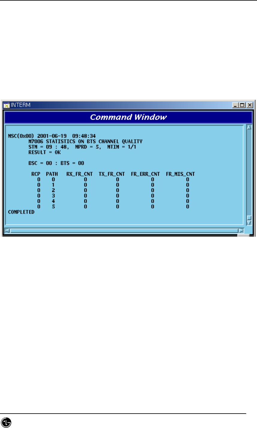
4.7.3.4. Radio Channel Quality Statistics Function
This function measures (Channel Element) and reports error rate and other things on
radio channel between mobile subscriber and BTS.
Command : STAT-CH:BSC=a[,BTS=b,MPRD=c,MTIM=d];
a : BSC : BSC number ( 0 ~ 11 )
b : BTS : BTS number ( 0 ~ 47 )
c : MPRD : Cycle(min) : Default 30min
d : Measuring Count : Default 4times
Display Results
Fig. 4.7-14 Radio Channel Statistics Output Results
(*)Refer to the appendix for the description of each item in the figure above.
4.7.3.5. Processor Statistics Function
This is the function that each processor measures CPU and IPC load of each main
processor at a given time to report to the BSM.
Command : STAT-PRC:CAN=a,BSC=b[,BTS=c,MPRD=d,MTIM=e];
a : CAN : CAN equipment processor inclusion matter
b : BSC : BSC number ( 0 ~ 11 )
c : BTS : BTS number ( 0 ~ 47 )
d : MPRD : Cycle(min) : Default 30min
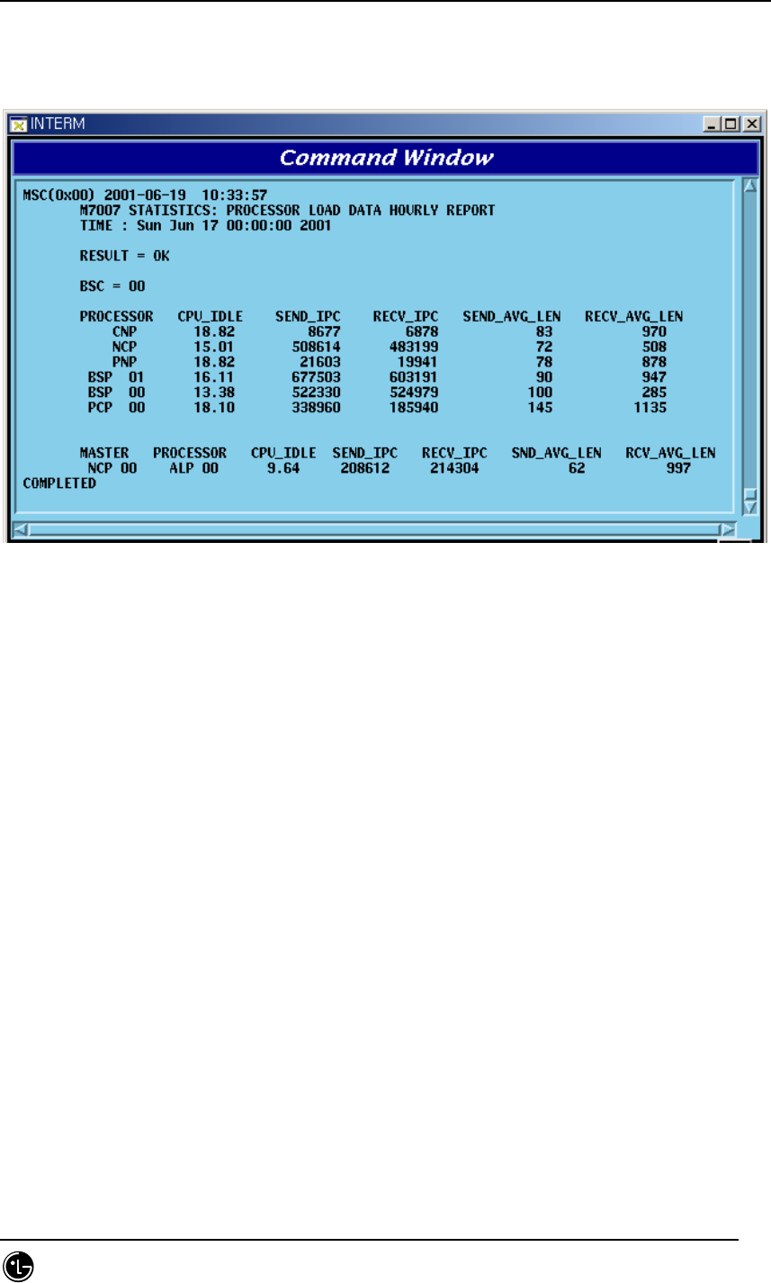
STAREX-IS BSM Manual
Page:508(877)
Issue:1.
0
SMD-011-PMA210
e : MTIM : Repeat Count : Default 4times
Display Results
Fig. 4.7-15 Processor Statistics Display Results
(*)Refer to the appendix for the description of each item in the figure above.
4.7.3.6. Selector Statistics Function
It is the statistics function that measures the occupying call, time, speed and bad frame
counts of the selector.
Commands : STAT-SLT:BSC=a,SMP=b[,SLP=c,MPRD=d,MTIM=e];
a : BSC : BSC number ( 0 ~ 11)
b : SMP : Selector Master Processor number ( 0 ~ 4)
c : SLP : Selector Processor number ( 0 ~ 19)
d : MPRD : Cycle(min) : Default 30min
e : MTIM : Count : Default 4times
Display Results
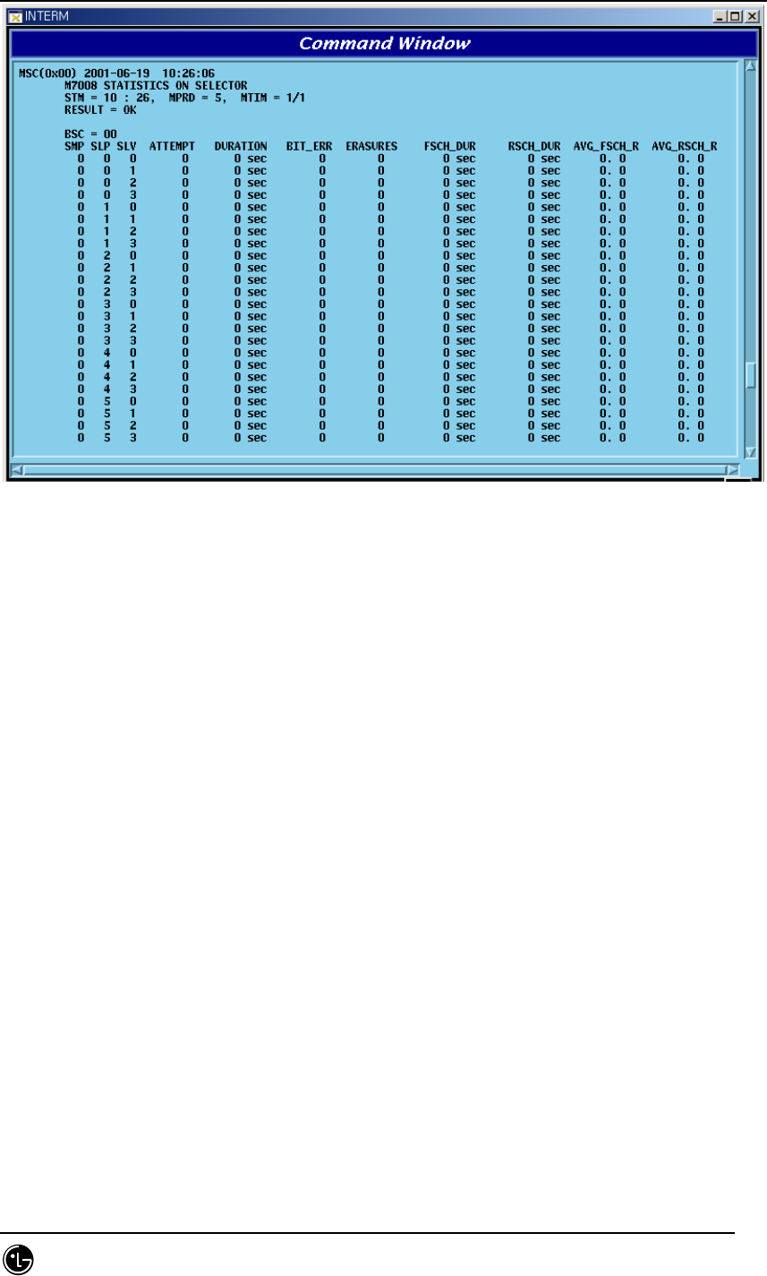
STAREX-IS BSM Manual
Page:509(877)
Issue:1.
0
SMD-011-PMA210
Fig. 4.7-16 Selector Statistics Display Results
(*)Refer to the appendix for the description of each item in the figure above.
4.7.3.7. Performance (Call Delay) Statistics Function
This is the function of BSP that measures and reports the setup delay (Time to Traffic,
Channel Assign) of originating/terminating signal to mobile subscribers.
Command : STAT-PERF:ITEM=a, BSC=b[,BTS=c,MPRD=d,MTIM=e];
a : ITEM : ALL-Measure originating and terminating,
ORG – Originating,
TRM- Terminating
b : BSC : BSC number ( 0 ~ 11 )
c : BTS : BTS number ( 0 ~ 47 )
d : MPRD : Cycle(min) : Default 30min
e : MTIM : Repeat Count : Default 4times
Display Results
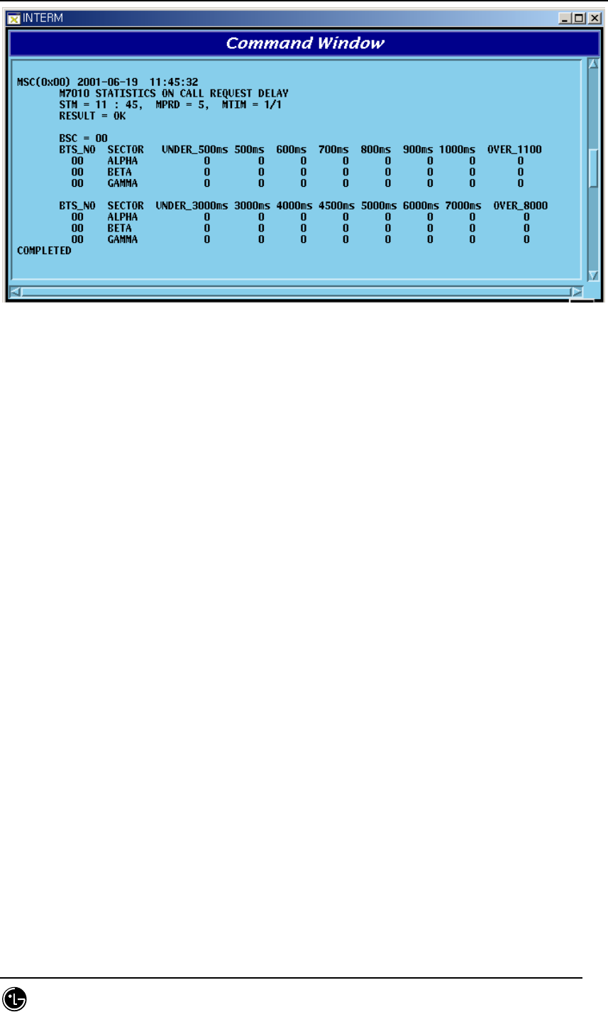
STAREX-IS BSM Manual
Page:510(877)
Issue:1.
0
SMD-011-PMA210
Fig. 4.7-17 Call Delay Performance Statistics Display Results
(*)Refer to the appendix for the description of each item in the figure above.
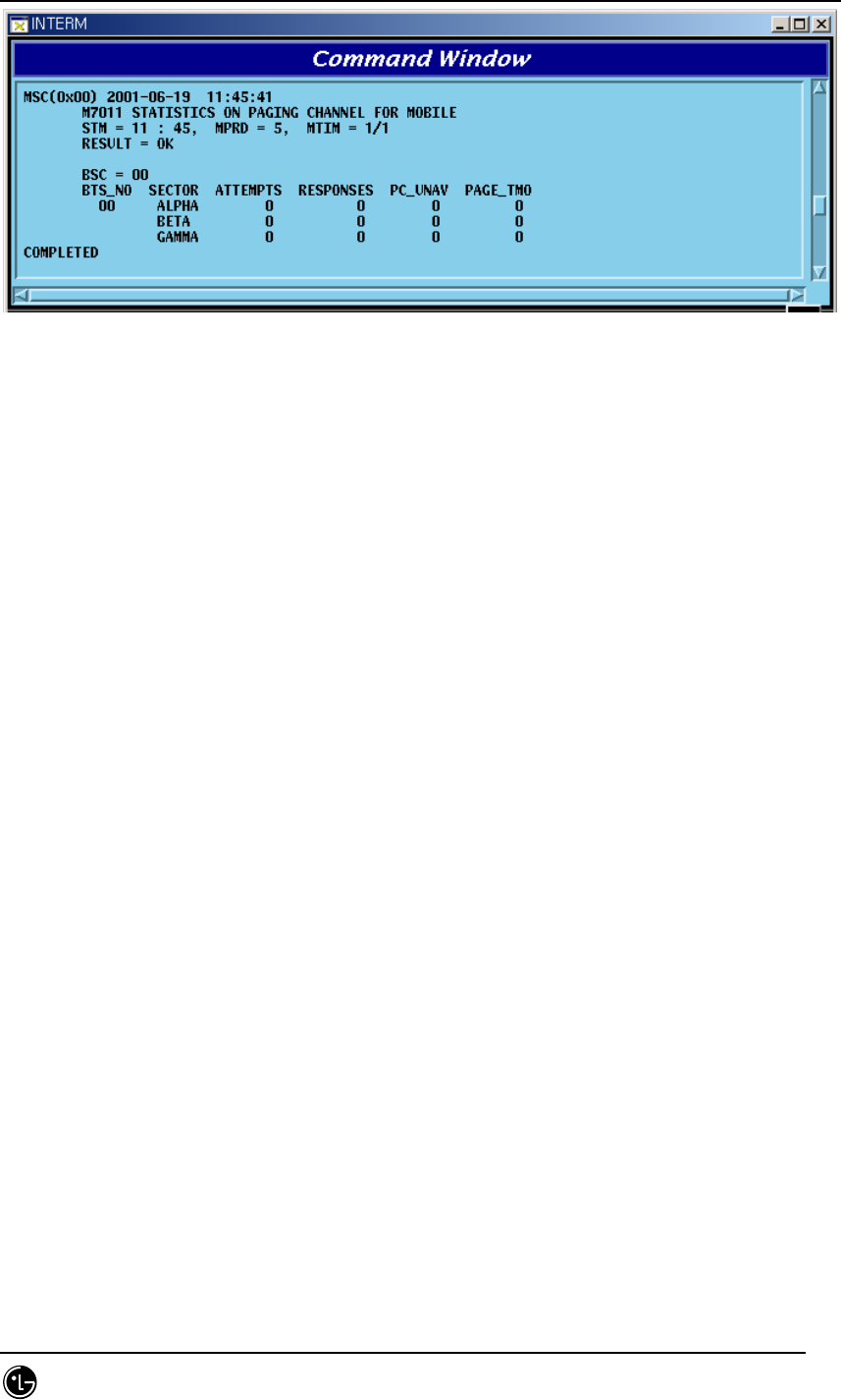
4.7.3.8. Paging Statistics Function
This is the function of BSP to measure and report the attempt, success and failure
counts of paging to the mobile subscriber.
Command : STAT-PAGE:BSC=a[,BTS=b, MPRD=c, MTIM=d];
a: BSC : BSC number( 0 ~ 11 )
b: BTS : BTS number( 0 ~ 47 )
c: MPRD : Cycle(min) : Default 30min
d: MTIM : Repeat Count : Default 4times
Display Results
STAREX-IS BSM Manual
Page:511(877)
Issue:1.
0
SMD-011-PMA210
Fig. 4.7-18 Paging Statistics Display Results
(*)Refer to the appendix for the description of each item in the figure above.
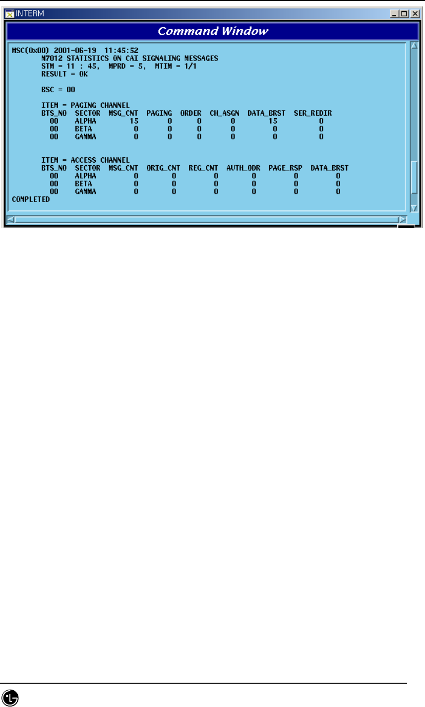
4.7.3.9. CAI Statistics Function
This is the function of BSP to measure and report the CAI signaling message at a given
time which is transmitted and received by access channel and paging channel.
Command : STAT-CAI:ITEM=a,BSC=b[,BTS=c,MPRD=d,MTIM=e];
a : ITEM : ALL – Access, Paging channel both to be measured
PC – Paging channel only to be measured
AC – Access channel only to be measured
b : BSC : BSC number ( 0 ~ 11 )
c : BTS : BTS number ( 0 ~ 47 )
d : MPRD : Cycle(min) : Default 30min
e : MTIM : Repeat Count : Default 4times
Display Count
STAREX-IS BSM Manual
Page:512(877)
Issue:1.
0
SMD-011-PMA210
Fig. 4.7-19 CAI Statistics Display Results
(*)Refer to the appendix for the description of each item in the figure above.
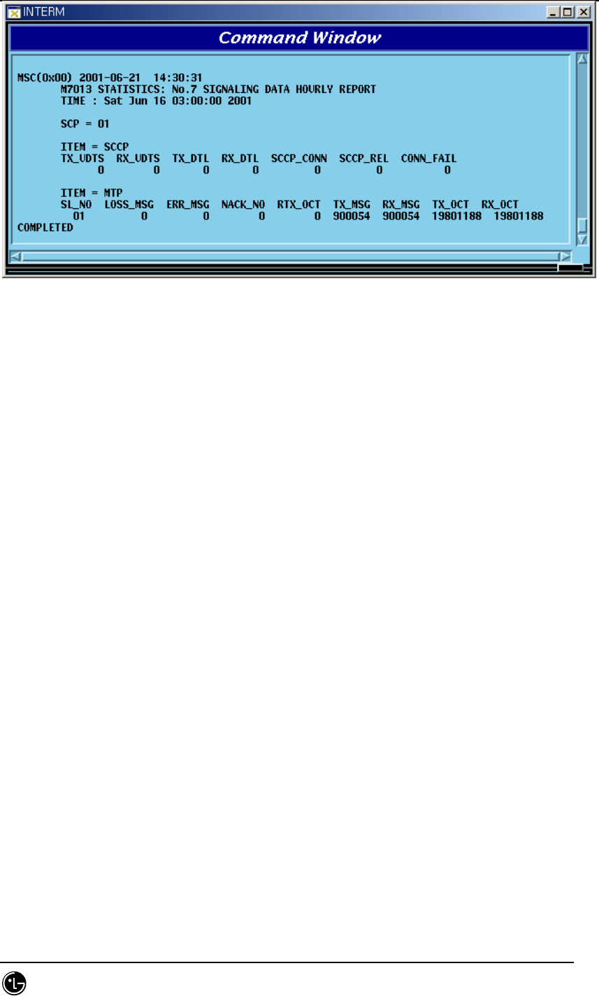
4.7.3.10. No.7 Signaling Statistics
No.7 signaling is the function of SCP to collect by sorting into MTP and SCCP, and
report it to the BSM.
Command : STAT-NO7:ITEM=a,SCP=b[,MPRD=c,MTIM=d];
a : ITEM : MTP, SCCP or ALL
b : SCP : SCP(BSC) Number(0~11)
c : MPRD : execution cycle(5~60min, default:30min)
d : MTIM : execution count(1~100, default:4)
Display Results
STAREX-IS BSM Manual
Page:513(877)
Issue:1.
0
SMD-011-PMA210
Fig. 4.7-20 No.7 Signaling Statistics Display Results
(*)Refer to the appendix for the description of each item in the figure above.
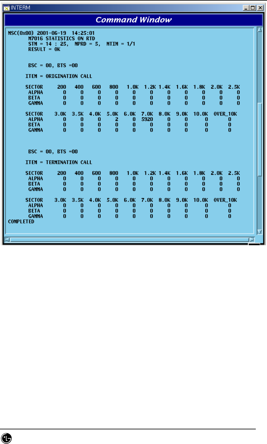
4.7.3.11. RTD Statistics
Round Trip Delay Statistics: BSP collects and reports the converted time from BTS
antenna to BTS antenna via MS into distance.
Command : STAT-RTD:BSC=a,BTS=b[,MPRD=c,MTIM=d];
a : BSC : BSC number ( 0 ~ 11 )
b : BTS : BTS number ( 0 ~ 47 )
c : MPRD : Cycle(min) : Default 30min
d : MTIM : Repeat Count : Default 4times
Display Results
STAREX-IS BSM Manual
Page:514(877)
Issue:1.
0
SMD-011-PMA210
Fig. 4.7-21 RTD Statistics Display Results
(*)Refer to the appendix for the description of each item in the figure above.
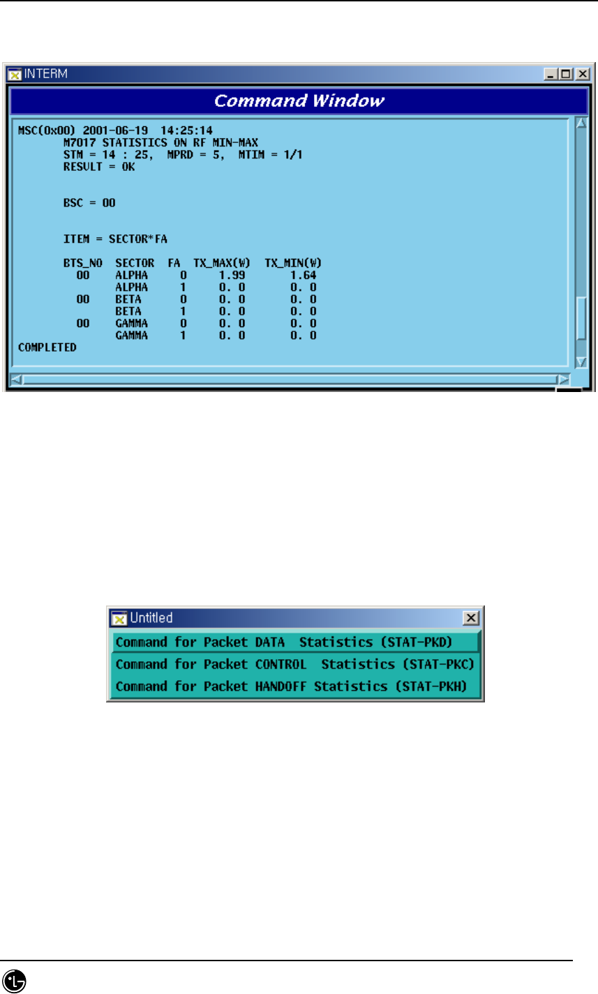
4.7.3.12. RF MIN/MAX Statistics Function
RFP reports to the BSP concerning TX power at a given time with the minimum and
maximum value.
Command : STAT-RF:BSC=a,BTS=b,MPRD=c,MTIM=d;
a : BSC : BSC number ( 0 ~ 11 )
b : BTS: BTS number ( 0 ~ 47 )
c : MPRD : Cycle(min) : Default 30min
d : MTIM : Repeat Count : Default 4min
STAREX-IS BSM Manual
Page:515(877)
Issue:1.
0
SMD-011-PMA210
Display Results
Fig. 4.7-22 RF Min/Max Statistics Function Display Results
(*)Refer to the appendix for the description of each item in the figure above.
4.7.4. Packet Related
Packet related statistics function is as followed.
Fig. 4.7-23 Packet Statistics Function
4.7.4.1. Packet Data Statistics Function
PIP collects average data transmission between BSC and PDSN and reports it to the
BSM through PCP.
Command : STAT-PKD:PCP=a,SHELF=b[,PIP=c, MPRD=d, MITM=e];
STAREX-IS BSM Manual
Page:516(877)
Issue:1.
0
SMD-011-PMA210
a : PCP : PCP number ( 0 ~ 2 )
b : SHELF : Shelf number ( SHELF 0, SHELEF 1, ALL)
c : PIP : PIP number ( 0 ~ 11 )
d : MPRD : cycle(min) : Default 30min
e : MTIME : Repeat Count : count 4times
Display Results
Fig. 4.7-24 Packet Data Statistics Display Results
(*)Refer to the appendix for the description of each item in the figure above.
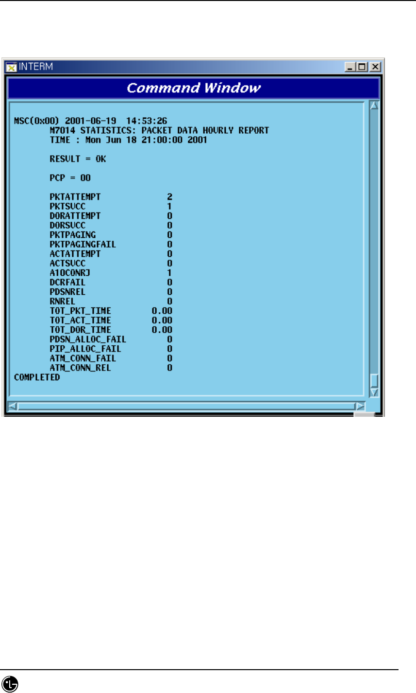
4.7.4.2. Packet Control Statistics Function
It is the function to collect and report to BSM regarding the following: the call attempt
count and call success count, the attempt count and success count of packet call
transition from dormant status to active status, and each average call holding time
between BSC and PDSN.
Command : STAT-PKC:PCP=a[,MPRD=b,MTIM=c];
a : PCP : PCP number ( 0 ~ 2 )
b : MPRD : cycle(min) : Default 30min
c : MTIM : Repeat Count : Default 4min
STAREX-IS BSM Manual
Page:517(877)
Issue:1.
0
SMD-011-PMA210
Display Results
Fig. 4.7-25 Packet Control Statistics Function Results Display
(*)Refer to the appendix for the description of each item in the figure above.
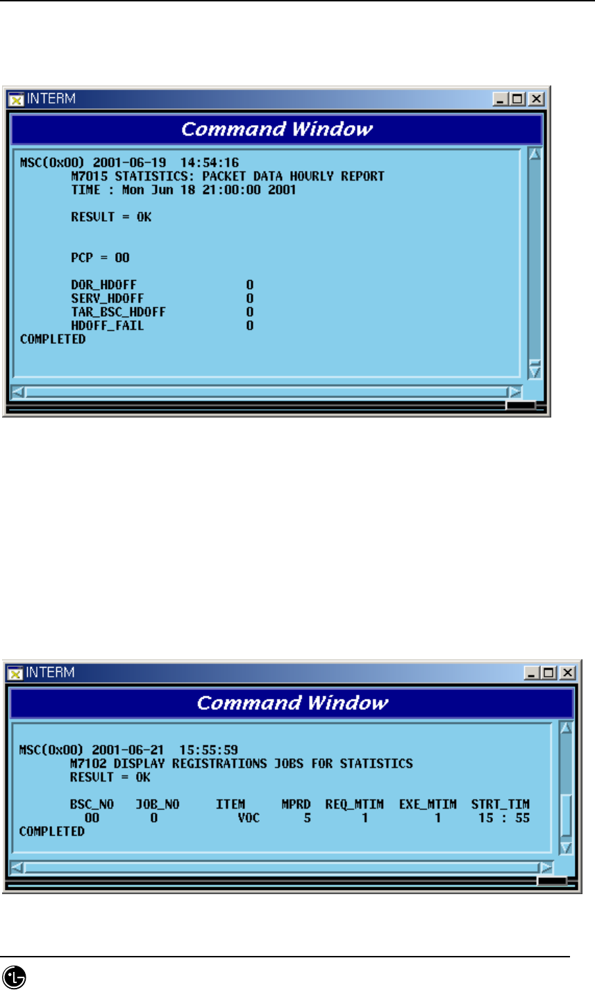
4.7.4.3. Packet Handoff Statistics Function
PCP collects and reports the following statistics data to BSM: attempt and failure
count of inter BSC hard handoff occurred in the packet traffic procedure by dormant or
active status.
Command : STAT-PKH:PCP=a[,MPRD=b,MTIM=c];
a : PCP : PCP number ( 0 ~ 2 )
b : MPRD : Cycle(min) : Default 30min
STAREX-IS BSM Manual
Page:518(877)
Issue:1.
0
SMD-011-PMA210
c : MTIM : Repeat Count : Default 4times
Display Results
Fig. 4.7-26 Packet Handoff Statistics Function Display Results
(*)Refer to the appendix for the description of each item in the figure above.
4.7.5. Other Statistics Related Commands
4.7.5.1. Displaying Statistics List under Execution
Displaying statistics list under execution at the request of present user.
Command : DIS-STAT-JOB;
Display Results
Fig. 4.7-27 Display Results of Statistics List under Execution

STAREX-IS BSM Manual
Page:519(877)
Issue:1.
0
SMD-011-PMA210
4.7.5.2. Statistics Cancel Command
This is the function to cancel On Demand statistics command under execution.
Command : CANC-STAT:[BSC=a,]JOB=b;
a : BSC : BSC number( 0 ~ 11 )
b : JOB : Statistics number ( 0 ~ 7)
4.7.5.3. Hourly / Daily Statistics Data Display Command
This is the function that displays the hourly statistics data collected and stored by
BSM through the BSM Interm window.
Hourly Statistics Display Command:
DIS-HLY-DATA:HOUR=a,ITEM=b,BSC=c,BTS=d;
a : HOUR : Time (00 ~ 23)
b : ITEM : Kinds of Statistics
c : BSC : BSC number ( 0 ~ 11 )
d : BTS : BTS number ( 0 ~ 47 )
Daily Statistics Display:
DIS-HLY-DATA:WEEK=a,HOUR=b,ITEM=c,BSC=d,BTS=e;
a : WEEK : Day of the Week ( MON/TUE/WED/THU/FRI/SAT/SUN)
b : HOUR : hour (00 ~ 23)
c : ITEM : Kinds of Statistics
d : BSC : BSC number ( 0 ~ 11 )
e : BTS : BTS number ( 0 ~ 47 )
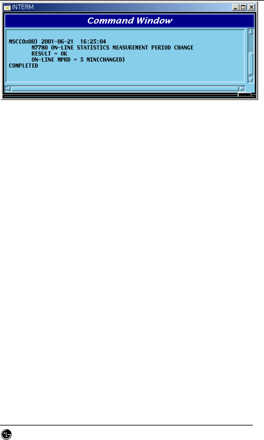
4.7.5.4. On Line Statistics Period Change
This is the function to change the period (basically 5minute) of online statistics(real-
time traffic statistics) collected by CCP.
Command : CHG-ONLINE-MPRD:MPRD=a;
a : MPRD : Period(min) to be changed
Execution Results
STAREX-IS BSM Manual
Page:520(877)
Issue:1.
0
SMD-011-PMA210
Fig. 4.7-28 Results of Changing On Line Statistics Period

STAREX-IS BSM Manual
Page:521(877)
Issue:1.
0
SMD-011-PMA210
4.8. Alarm/Fault Command
The fault function of BSM is configured into the following: displayed on the console
window to the generated alarm and fault, displayed only at user’s request to the
23items below.
Table 4-4.8-1 Alarm/Fault Related Command List
Comment Related Command
Displaying Inhibited Alarm List DIS-INH-ALM;
Displaying Audible Alarm
Status
DIS-AUD-STS;
Displaying Inhibited Fault List DIS-INH-FLT;
Displaying Present Alarm
Status
DIS-ALM-STS;
Displaying Suppressed Alarm DIS-SUP-ALM;
Displaying Information about
Alarm Message
DIS-ALM-INFO;
Displaying Alarm List DIS-ALM-LIST;
Displaying Suppressed Fault DIS-SUP-FLT;
Inhibiting Alarm Message
Display
INH-ALM-MSG;
Inhibiting Audible Alarm INH-AUD-ALM;
Inhibiting Fault Message
Display
INH-FLT-MSG;
Suppressing Alarm Message SUP-ALM-MSG;
Suppressing Fault Message SUP-FLT-MSG;
Allowing Inhibited Alarm
Message
ALW-ALM-MSG;
Allowing Inhibited Audible
Alarm
ALW-AUD-ALM;
Allowing Inhibited Fault
Message
ALW-FLT-MSG;
Releasing Suppressed Alarm
Message
REL-ALM-MSG;

STAREX-IS BSM Manual
Page:522(877)
Issue:1.
0
SMD-011-PMA210
Releasing Suppressed Fault
Message
REL-FLT-MSG;
Displaying Environment
Alarm
DIS-ENV-STS
Setting Environment Alarm
FLAG
SET-ENV-FLAG
Setting Environment Alarm
Time
SET-ENV-TIME
Setting Environment Alarm
Temperature
SET-ENV-TEMP
SET-ENV-HUMI
RST-ECV-STS
CLR-ENV-HIST
STAREX-IS BSM Manual
Page:523(877)
Issue:1.
0
SMD-011-PMA210
4.8.1. Alarm/Fault Display
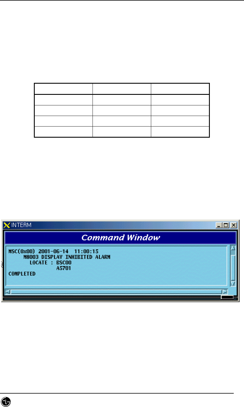
4.8.1.1. Display Command of Inhibited Alarm Message List
This is the command to display the list of the alarm message whose display is inhibited.
Check the Inhibit status when the alarm to be generated is not generated; if it is not
inhibited, check the Suppress status.
Table 4-4.8-2 The meaning of Input by BSC Number and BTS Number
BSC BTS Meaning
Input Input BTS
Input X BSC
X X CAN
X Input Input Error
*Note) The applying scope of the table above equally applied to the Alarm/Fault
related command.
• Command DIS-INH-ALM:[BSC=a],[BTS=b];
a : BSC Number(0 ~ 11)
b : BTS Number(0 ~ 47)
• Input DIS-INH-ALM:BSC=0;
• Display
Fig. 4.8-1 Display Result of the Display Inhibited Alarm Message List
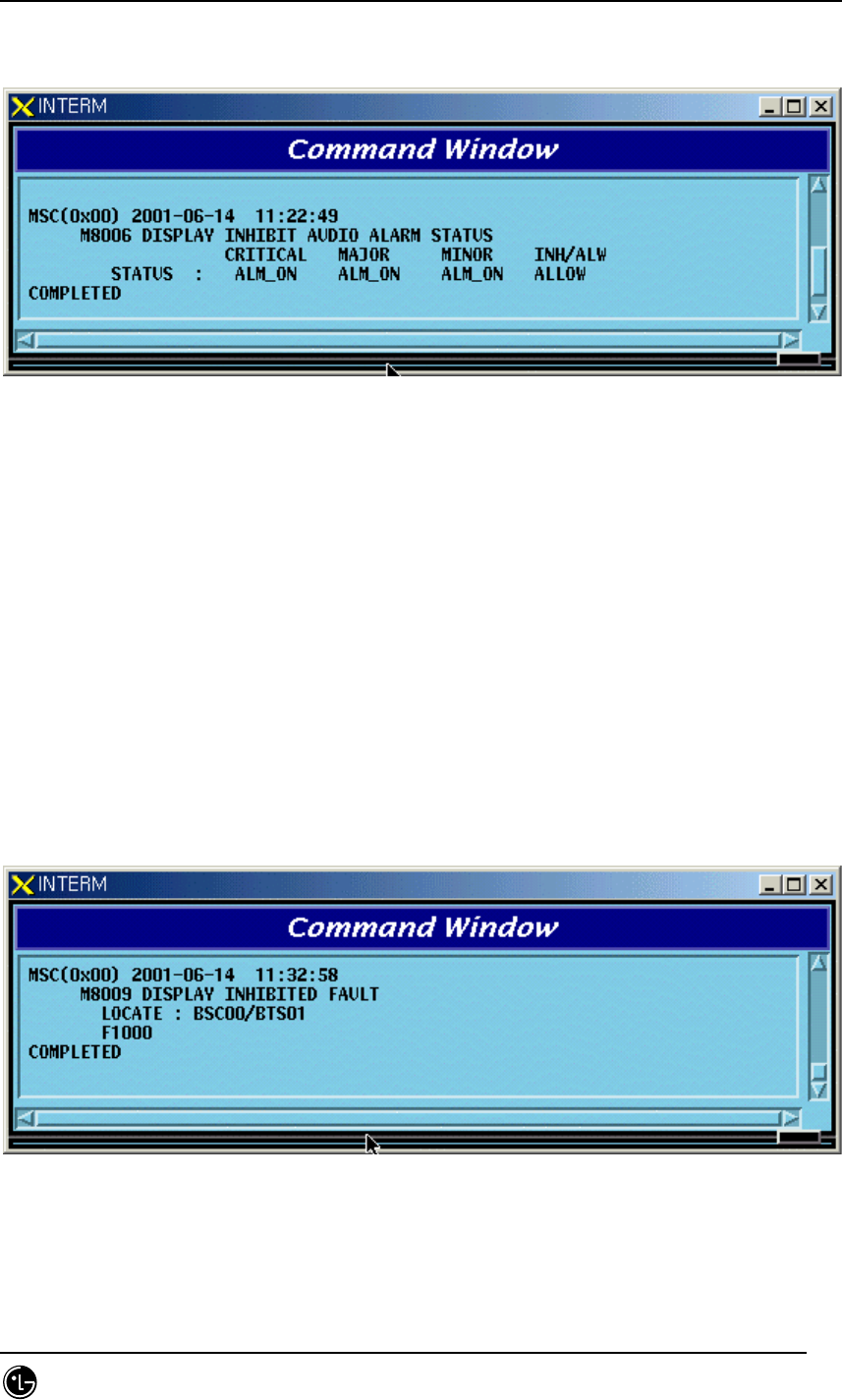
4.8.1.2. Display Command for the Audible Alarm Status
This command displays the alarm panel status, presently generated alarm status and
inhibition status of the audible alarm.
STAREX-IS BSM Manual
Page:524(877)
Issue:1.
0
SMD-011-PMA210
• Command DIS_AUD-STS;
• Display
Fig. 4.8-2 Display Result of the Display Command for Audible Alarm Status
4.8.1.3. Display Command for Inhibited Fault Message List
This is the command for the display inhibited fault messages to display their list. If
fault message to be generated were not generated this command would be needed to
check the Inhibit status.
• Command DIS-INH-FLT:[BSC=a],[BTS=b];
a : BSC Number(0 ~ 11)
b : BTS Number(0 ~ 47)
• Input DIS-INH-FLT:BSC=0, BTS=1;
• Display
Fig. 4.8-3 Display Result of the List for the Display Inhibited Fault Message
STAREX-IS BSM Manual
Page:525(877)
Issue:1.
0
SMD-011-PMA210
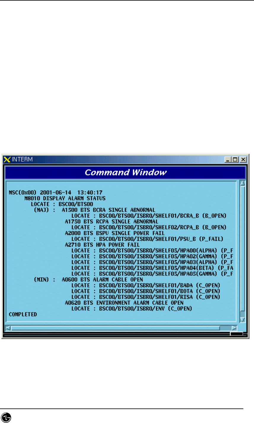
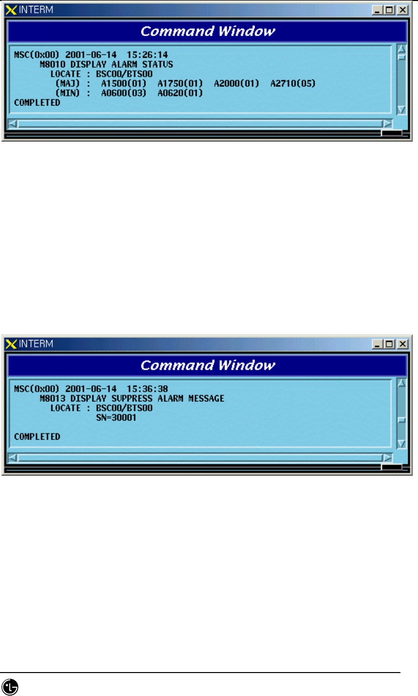
4.8.1.4. Display Command for the Present Alarm Status
This is the display command for the information about the presently generated alarm.
If the user would like to see the alarm code only, input nothing or OFF in the Detail
Option.
• Command DIS-ALM-STS[:BSC=a],[BTS=b],[DETAIL=c];
a : BSC Number(0 ~ 11)
b : BTS Number(0 ~ 47)
c : DETAIL Option(ON/OFF)
ON : Alarm Code + Alarm Info. + Alarm Generated Location
OFF: Alarm Code + Corresponding Alarm count(default)
(1) In the case of DETAIL = ON
• Input DIS-ALM-STS:BSC=0,BTS=0,DETAIL=ON;
• Display
Fig. 4.8-4 Display Result of Display Command for the Present Alarm Status
(2) In the case of DETAIL = OFF
• Input DIS-ALM-STS:BSC=0,BTS=0,DETAIL=OFF;
• Display
STAREX-IS BSM Manual
Page:526(877)
Issue:1.
0
SMD-011-PMA210
Fig. 4.8-5 Display Result of Display Command for Present Alarm Status
4.8.1.5. Display Command for Suppressed Alarm Message
This is the command for suppress alarm message to be displayed.
• Command DIS-SUP-ALM:[BSC=a],[BTS=b];
a : BSC Number(0 ~ 11)
b : BTSNumber(0 ~ 47)
• Input DIS-SUP-ALM:BSC=0,BTS=0;
• Display
Fig. 4.8-6 Display Result of Display Command for the Suppressed Alarm Message
4.8.1.6. Display Command for the Information about Alarm Message
This is the command to display the defined grade of the alarm message and alarm
message information.
• Command DIS-ALM-INFO:AN=a;
a : Alarm Code Number(100 ~ 9999)
• Input DIS-ALM-INFO:AN=1000; or DIS-ALM-INFO:1000;
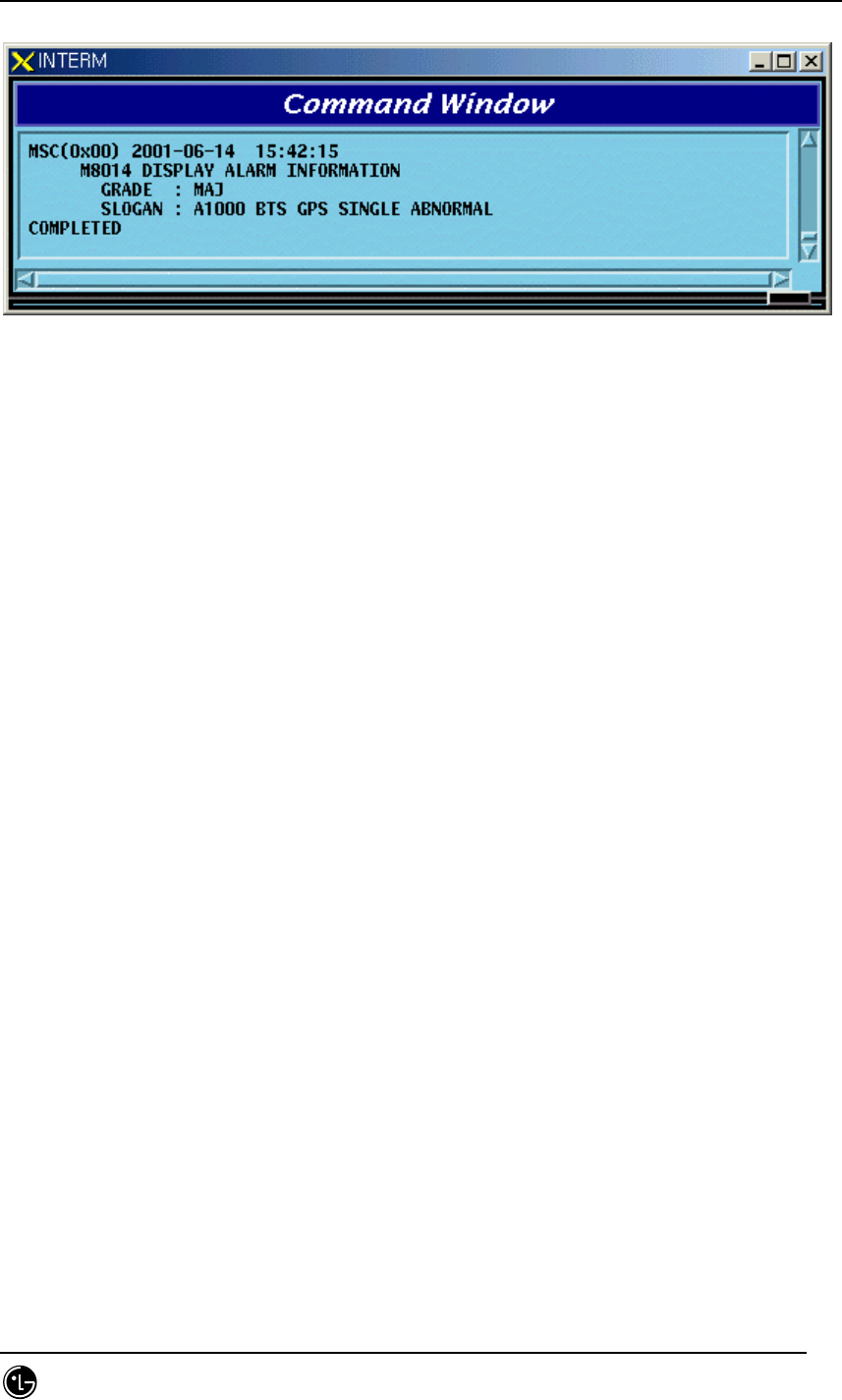
STAREX-IS BSM Manual
Page:527(877)
Issue:1.
0
SMD-011-PMA210
• Display
Fig. 4.8-7 Display Result of Display Command for Information about the Alarm Message
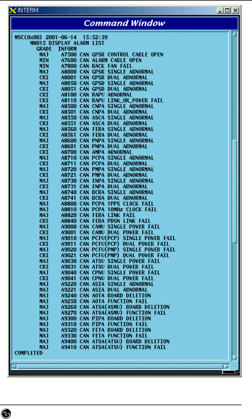
4.8.1.7. Display Command for Alarm List
This is the command to display the list for all kinds of alarm.
• Command DIS-ALM-LIST:[SUB-SYS=a];
a : Subsystem Name(CAN/BSC/BTS/ALL)
• Input DIS-ALM-INFO:CAN;
• Display
STAREX-IS BSM Manual
Page:528(877)
Issue:1.
0
SMD-011-PMA210
Fig. 4.8-8 Display Result of Display Command for the Information about Alarm List
STAREX-IS BSM Manual
Page:529(877)
Issue:1.
0
SMD-011-PMA210
4.8.1.8. Display Command for the List of the Suppressed Fault Message
This is the command to display the Fault Source Code List for the suppressed fault
message.
• Command DIS-SUP-FLT:[BSC=a],[BTS=b];
a : BSC Number(0 ~ 11)
b : BTS Number(0 ~ 47)
• Input DIS-SUP-FLT:BSC=0,BTS=0;
• Display
Fig. 4.8-9 Display Result of Display Command for the Suppress Fault Message List
4.8.2. Alarm/Fault Inhibition
4.8.2.1. Inhibition Command for Alarm Message
This is the function to inhibit the alarm message to be displayed on the console
window. If any Alarm Code is not designated it inhibits the entire alarm message
generated in the designated system.
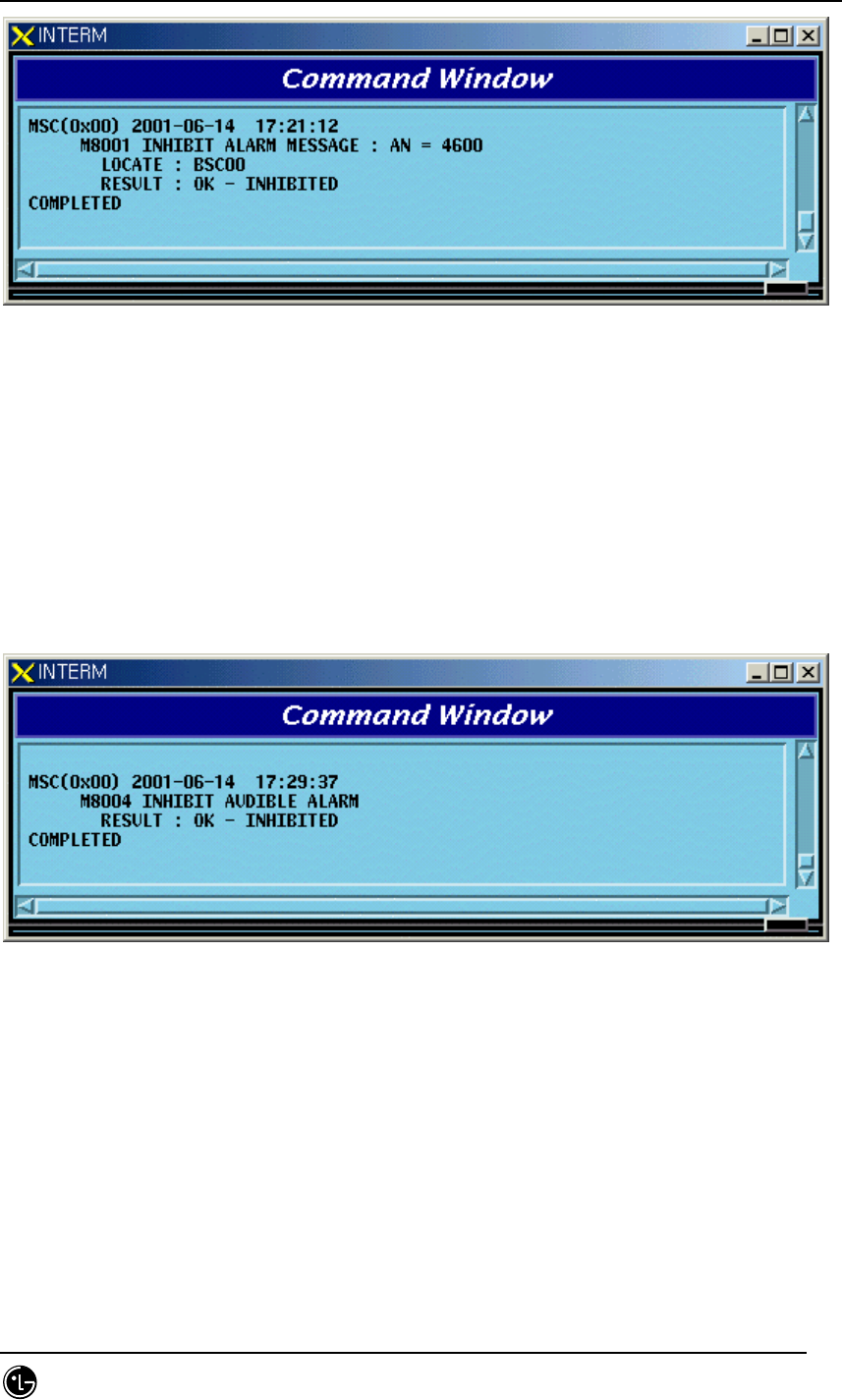
• Command INH-ALM-MSG:[BSC=a],[BTS=b],[AN=c];
a : BSC Number(0 ~ 11)
b : BTS_GRP Number(0 ~ 47)
c : Alarm Code Number(0 ~ 9999)
• Input INH-ALM-MSG:BSC=0,AN=4600;
• Display
STAREX-IS BSM Manual
Page:530(877)
Issue:1.
0
SMD-011-PMA210
Fig. 4.8-10 Display Result of Display Inhibition for Alarm Message
*Note) AN : Alarm Number
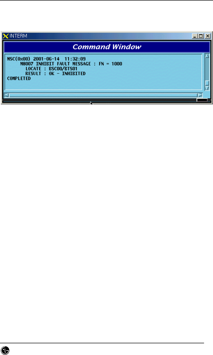
4.8.2.2. Inhibition Command for Audible Alarm
The audible alarm can be inhibited by the grade and it is applied to all kinds of alarm.
• Command INH-AUD-ALM
• Display
Fig. 4.8-11 Display Result of Inhibition Command for Audible Alarm
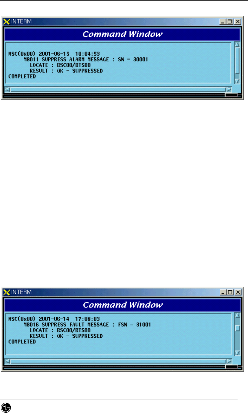
4.8.2.3. Inhibition Command for Fault Message
This is the function to inhibit the display of the fault message. If any fault code is not
designated, it inhibits all the fault codes.
• Command INH-FLT-MSG:[BSC=a],[BTS=b],[FN=c];
a : BSC Number(0 ~ 11)
b : BTS Number(0 ~ 47)
STAREX-IS BSM Manual
Page:531(877)
Issue:1.
0
SMD-011-PMA210
c : Fault Code Number
• Input INH-FLT-MSG:BSC=0,BTS=0,FN=1000;
• Display
Fig. 4.8-12 Display Result of Inhibition/Allowance for Fault Message Display
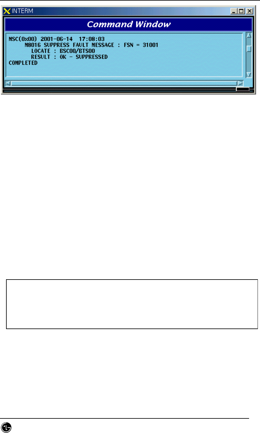
4.8.2.4. Alarm Message Suppress Command
This command is used for the following cases: when previously checked alarm(by
the user) is generating and burden BSM; when suppressing the report for the alarm
message from subsystem in order to monitor other important message.
This is the command blocking the message itself for the unnecessary alarm contrary
to the command (INH-ALM-MSG) which inhibits the alarm message to be displayed on
the BSM console window.
• Command SUP-ALM-MSG:[BSC=a],[BTS=b],[SRC_CODE=c];
a : BSC Number(0 ~ 11)
b : BTS Number(0 ~ 47)
c : Alarm Source Code Number(1 ~ 9999)
• Input SUP-ALM-MSG:BSC=0,BTS=0,SRC_CODE=30001;
• Display
STAREX-IS BSM Manual
Page:532(877)
Issue:1.
0
SMD-011-PMA210
Fig. 4.8-13 Display Result of the Suppress Alarm Message Command
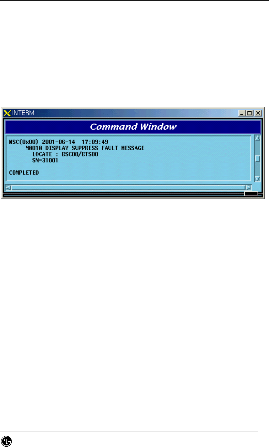
4.8.2.5. Fault Message Suppress Command
This command is used for the following cases: when previously checked fault
message(by the user) is generating and burden BSM; when suppressing the report for
the fault message from subsystem in order to monitor other important message.
This is the command blocking the message itself for the unnecessary fault message
contrary to the command (INH-FLT-MSG) which inhibits the fault message to be
displayed on the BSM console window.
• Command SUP-FLT-MSG:[BSC=a],[BTS=b],[SRC_CODE=c];
a : BSC Number(0 ~ 11)
b : BTS Number(0 ~ 47)
c : Fault Source Code Number(1 ~ 1000)
• Input SUP-FLT-MSG:BSC=0,BTS=0,SRC_CODE=31001;
• Display
Fig. 4.8-14 Display Result for the Fault Message Suppress Command
STAREX-IS BSM Manual
Page:533(877)
Issue:1.
0
SMD-011-PMA210
4.8.3. Alarm/Fault Control
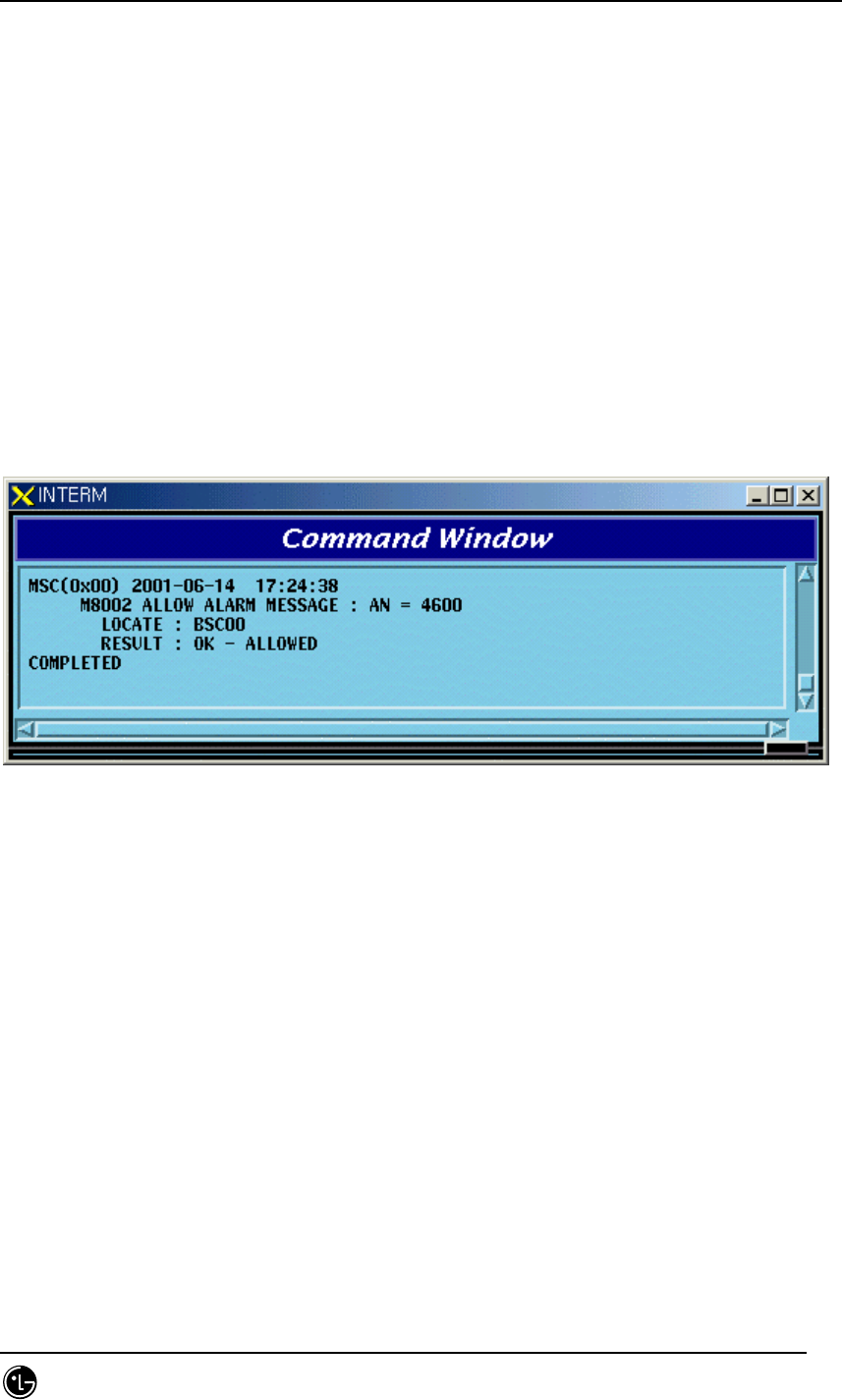
4.8.3.1. Allowance Command for Inhibited Alarm Message Display
This is the command to allow randomly inhibited alarm message for display by the user.
If any specific alarm code is not designated, all the inhibited alarm code for display in
the designated system is allowed.
• Command ALW-ALM-MSG:[BSC=a],[BTS=b],[AN=c];
a : BSC Number(0 ~ 11)
b : BTS Number(0 ~ 47)
c : Alarm Code Number(0 ~ 9999)
• Input ALW-ALM-MSG:BSC=0,AN=4600;
• Display
Fig. 4.8-15 Display Result of Allowance for Alarm Message Display Inhibition
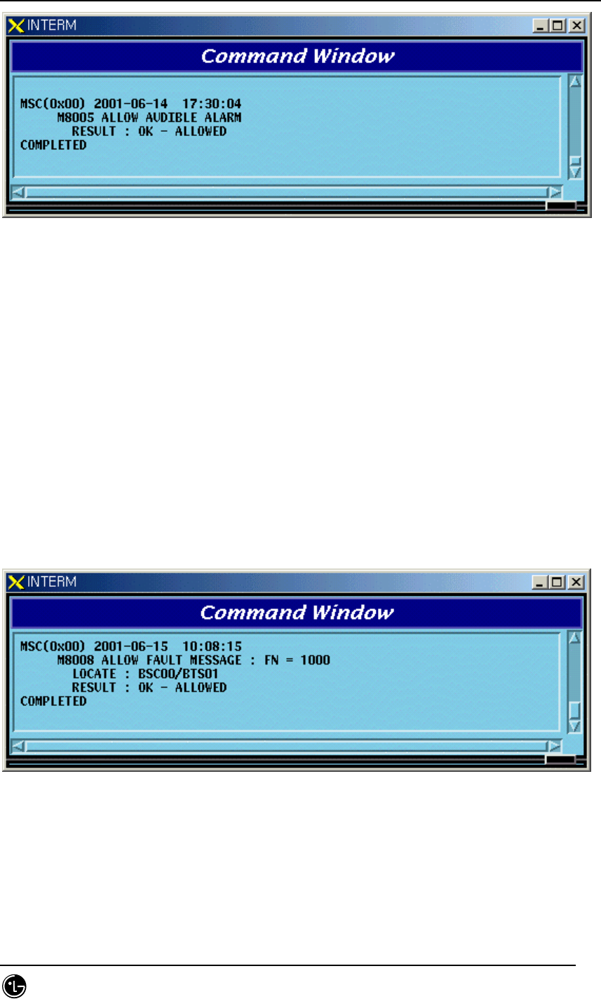
4.8.3.2. Allowance Command for Inhibited Audible Alarm
This is the command to allow inhibited audible alarm.
• Command ALW-AUD-ALM
• Display
STAREX-IS BSM Manual
Page:534(877)
Issue:1.
0
SMD-011-PMA210
Fig. 4.8-16 Display Result of Allowance Command for Inhibited Audible Alarm
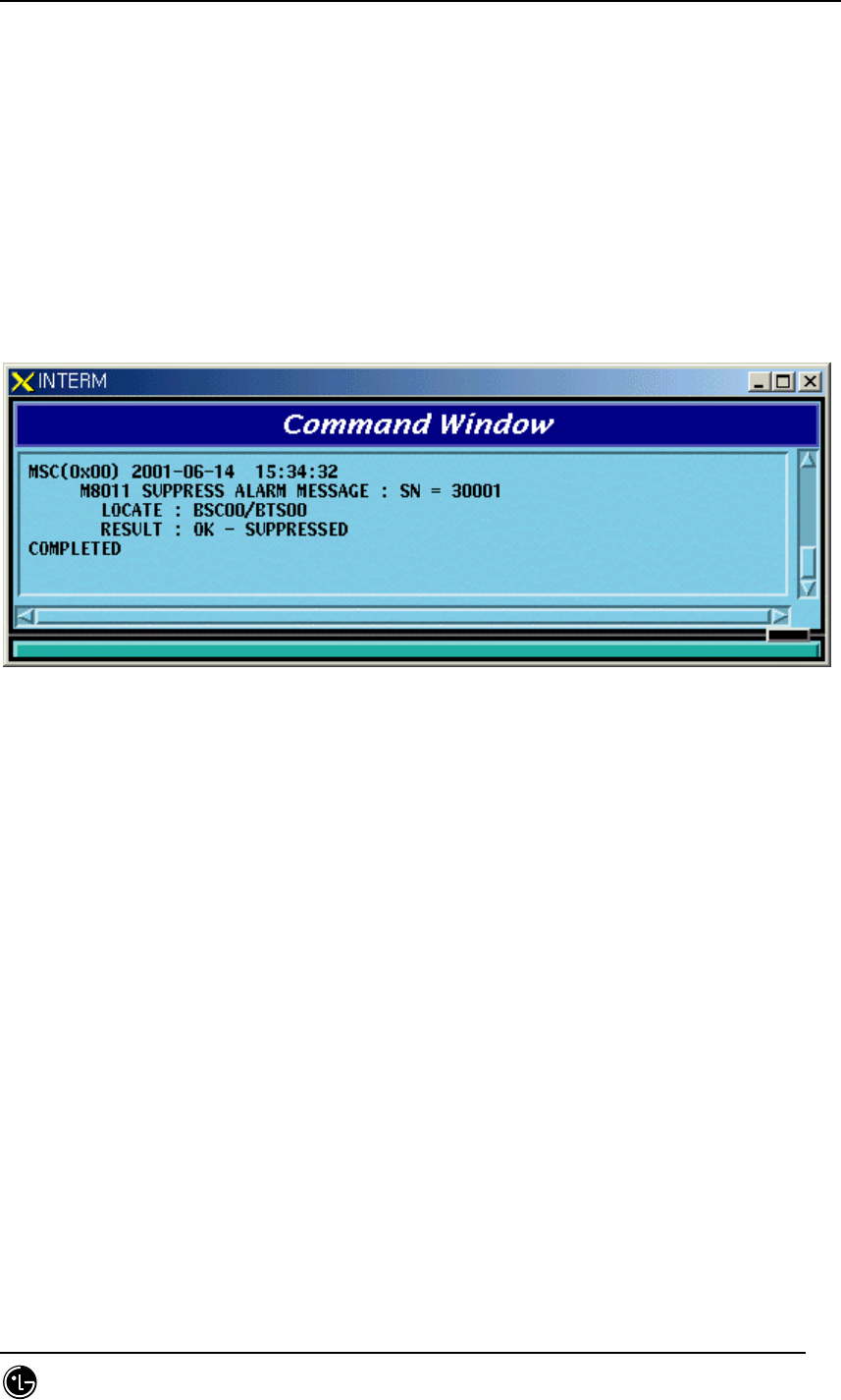
4.8.3.3. Allowance Command for Inhibited Fault Message Display
This is the command to allow randomly inhibited fault message by the user. If any
specific alarm code is not designated, all the inhibited fault code for display is allowed.
• Command ALW-FLT-MSG:[BSC=a],[BTS=b],[FN=c];
a : BSC Number(0 ~ 11)
b : BTS Number(0 ~ 47)
c : Fault Code Number(1000 ~ 9999)
• Input ALW-FLT-MSG:BSC=0,BTS=1,FN=1000;
• Display
Fig. 4.8-17 Display Result for Allowing Fault Message Display Inhibition
4.8.3.4. Release Command for Suppressed Alarm Message
This is the command to release randomly suppressed alarm message by the user. If
there were any follow-up measures after suppressing and the suppressing is not
STAREX-IS BSM Manual
Page:535(877)
Issue:1.
0
SMD-011-PMA210
needed any more, it is highly recommended to release the suppress by this command.
If the alarm is not generated in the required situation the suppress matter should be
checked.
• Command REL-ALM-MSG:[BSC=a],[BTS=b],[SRC_CODE=c];
a : BSC Number(0 ~ 11)
b : BTS Number(0 ~ 47)
c : Alarm Source Code Number(1 ~ 9999)
• Input REL-ALM-MSG:BSC=0,BTS=0,SRC_CODE=30001;
• Display
Fig. 4.8-18 Display Result of Release Command for Suppressed Alarm Message
4.8.3.5. Release Command for Suppressed Fault Message
This is the command to release randomly suppressed fault message by the user. If
there were any follow-up measures to the suppressed message and the suppressing is
not needed any more, it is recommended to release the suppress by this command.
• Command REL-FLT-MSG:[BSC=a],[BTS=b],[SRC_CODE=c];
a : BSC Number(0 ~ 11)
b : BTS Number(0 ~ 47)
c : Fault Source Code Number(1 ~ 1000)
• Input REL-FLT-MSG:BSC=0,BTS=0,SRC_CODE=31001;
• Display
STAREX-IS BSM Manual
Page:536(877)
Issue:1.
0
SMD-011-PMA210
Fig. 4.8-19 Display Result of Release Command for Suppressed Fault Message
4.8.4. Environment Alarm Control
4.8.4.1. Environment Alarm Flag set Command
This is the command to decide (ON/OFF) whether to receive the alarm, which is
sensed by the sensor of environment monitoring module, normally or not. ON means
receiving the alarm normally and OFF means non-receiving the alarm.
• Command SET-ENV-FLAG:[BSC=a],[BTS=b],[CMD=c],[FLAG=d];
a : BSC Number(0 ~ 11)
b : BTS Number(0 ~ 47)
c : Command
d : Flag(ON/OFF)
• Input SET-ENV-FLAG:
• Display
a : RECTIFIER_SHUT_DOWN_ALARM
FIRE
UPPER_FLOOD
LOWER_FLOOD
TEMPERATURE1
TEMPERATURE2
MSC(0x00) date time
M8030 SET ACU FLAG : a
LOCATE = b
RESEON = c

STAREX-IS BSM Manual
Page:537(877)
Issue:1.
0
SMD-011-PMA210
TEMPERATURE3
TEMPERATURE_CENTIGRADE_OPTION
HUMIDITY
b : Locate Information
c : #PROC_NOT_EQUIP
##PROC_ABNORMAL
##THIS COMMAND IS IN SERVICE
##NOK - BTS TYPE MISMATCH
##NOK - BAMA ABNORMAL
##NOK - ACU ABNORMAL
##NOK - RECTIFIER ABNORMAL
##NOK - BAMA NO RESPONSE
##NOK - ACU or REC NO RESPONSE
##NOK - ALREADY SET FLAG ON
##NOK - ALREADY SET FLAG OFF
##NOK - UNKNOWN REASON
##OK - SET FLAG COMPLETED
4.8.4.2. Environment Alarm Reset Command
This is the reset command for environment monitoring module and the rectifier.
• Command RST-ENV-STS:[BSC=a],[BTS=b],[CMD=c];
a : BSC Number(0 ~ 11)
b : BTS Number(0 ~ 47)
c : Command
• Input RST-ENV-STS:
• Display
a : ACU_COLD_BOOT
ACU_RESET
RECTIFIER_POWER_TURN
RECTIFIER_CONTOROLLER_RESET
MSC(0x00) date time
M8031 RESET ACU STATUS : a
LOCATE = b
RESEON = c

STAREX-IS BSM Manual
Page:538(877)
Issue:1.
0
SMD-011-PMA210
b : Locate Information
c : ##PROC_NOT_EQUIP
##PROC_ABNORMAL
##THIS COMMAND IS IN SERVICE
##NOK - BTS TYPE MISMATCH
##NOK - BAMA ABNORMAL
##NOK - ACU ABNORMAL
##NOK - RECTIFIER ABNORMAL
##NOK - BAMA NO RESPONSE
##NOK - ACU or REC NO RESPONSE
##NOK - UNKNOWN REASON
##OK - RESET COMPLETED
4.8.4.3. Environment Alarm History Clear Command
This is the command to clear all the history stored in the environment monitoring
module.
• Command CLR-ENV-HIST:[BSC=a],[BTS=b],[CMD=c];
a : BSC Number(0 ~ 11)
b : BTS Number(0 ~ 47)
c : Command
• Input CLR-ENV-HIST:
• Display
a : OP HISTORY
RUNNING HISTORY
b : Locate Information
c : ##PROC_NOT_EQUIP
##PROC_ABNORMAL
##THIS COMMAND IS IN SERVICE
##NOK - BTS TYPE MISMATCH
##NOK - BAMA ABNORMAL
MSC(0x00) date time
M8032 HISTORY CLEAR : a
LOCATE = b
RESEON = c

STAREX-IS BSM Manual
Page:539(877)
Issue:1.
0
SMD-011-PMA210
##NOK - ACU ABNORMAL
##NOK - RECTIFIER ABNORMAL
##NOK - BAMA NO RESPONSE
##NOK - ACU or REC NO RESPONSE
##NOK - UNKNOWN REASON
##OK - CLEAR HISTORY COMPLETED
4.8.4.4. Time Set Command
This is the command to set time (year/month/date/hour/minute/second) built in
environment monitoring module.
• Command SET-ENV-TIME:[BSC=a],[BTS=b],[YEAR=c],[MONTH=d],[DAY=e],
[HOUR=f],[MINUTE=g],[SECOND=h];
a : BSC Number(0 ~ 11)
b : BTS Number(0 ~ 47)
c : Year(1990 ~ 2049)
d : Month(1 ~ 12)
e : Day(1 ~ 31)
f : Hour(0 ~ 23)
g : Minute(0 ~ 59)
h : Second(0 ~ 59)
• Input SET-ENV-TIME:
• Display
a : Locate Information
b : #PROC_NOT_EQUIP
##PROC_ABNORMAL
##THIS COMMAND IS IN SERVICE
##NOK - BTS TYPE MISMATCH
##NOK - BAMA ABNORMAL
##NOK - ACU ABNORMAL
##NOK - RECTIFIER ABNORMAL
MSC(0x00) date time
M8033 SET ACU DATE AND TIME
LOCATE = a
RESEON = b

STAREX-IS BSM Manual
Page:540(877)
Issue:1.
0
SMD-011-PMA210
##NOK - BAMA NO RESPONSE
##NOK - ACU or REC NO RESPONSE
##NOK - UNKNOWN REASON
##OK - SET ACU TIME COMPLETED
4.8.4.5. Temperature Set Command
This is the command to set the temperature (high/low/middle)’s threshold value of
which the environment monitoring module takes control. If the temperature surpasses
the set threshold value, the alarm is generating.
• Command SET-ENV-TEMP:
[BSC=a],[BTS=b],[HI_TEMP=c],[LOW_TEMP=d],[MID_TEMP=e];
a : BSC Number(0 ~ 11)
b : BTS Number(0 ~ 47)
c : High Temperature(0 ~ 200)
d : Low Temperature(-20 ~ 200)
e : Middle Temperature(-20 ~ 200)
• Input SET-ENV-TEMP:
• Display
a : Locate Information
b : ##PROC_NOT_EQUIP
##PROC_ABNORMAL
##THIS COMMAND IS IN SERVICE
##NOK - BTS TYPE MISMATCH
##NOK - BAMA ABNORMAL
##NOK - ACU ABNORMAL
##NOK - RECTIFIER ABNORMAL
##NOK - BAMA NO RESPONSE
##NOK - ACU or REC NO RESPONSE
##NOK - UNKNOWN REASON
##OK - SET ACU TEMPERATURE COMPLETED
MSC(0x00) date time
M8034 SET ACU ALARM VALUE TEMPERATURE(HIGH/LOW/MIDDLE)
LOCATE = a
RESEON = b

STAREX-IS BSM Manual
Page:541(877)
Issue:1.
0
SMD-011-PMA210
4.8.4.6. Humidity Set Command
This is the command to set the threshold value of humidity of which the environment
monitoring module takes control. If humidity surpasses this threshold value, the alarm
is generating.
• Command SET-ENV-HUMI:[BSC=a],[BTS=b],[HI_HUMI=c];
a : BSC Number(0 ~ 11)
b : BTS Number(0 ~ 47)
c : High Humidity(0 ~ 100)
• Input SET-ENV-HUMI:
• Display
a : Locate Information
b : ##PROC_NOT_EQUIP
##PROC_ABNORMAL
##THIS COMMAND IS IN SERVICE
##NOK - BTS TYPE MISMATCH
##NOK - BAMA ABNORMAL
##NOK - ACU ABNORMAL
##NOK - RECTIFIER ABNORMAL
##NOK - BAMA NO RESPONSE
##NOK - ACU or REC NO RESPONSE
##NOK - UNKNOWN REASON
##OK - SET ACU HUMIDITY COMPLETED
4.8.4.7. Environment Alarm Display Command
This is the command to display the parameter value, flag status, history and other
things presently stored in the environment monitoring module.
MSC(0x00) date time
M8035 SET ACU HIGH HUMIDITY ALARM LIMITS VALUE
LOCATE = a
RESEON = b

STAREX-IS BSM Manual
Page:542(877)
Issue:1.
0
SMD-011-PMA210
• Command DIS-ENV-STS:[BSC=a],[BTS=b],[CMD=c],[RECORD_NO=d];
a : BSC Number(0 ~ 11)
b : BTS Number(0 ~ 47)
c : Command
d : Record Number(0 ~ 500)
• Input DIS-ENV-STS:
• Display
A : Command
B : Locate Information
C : ACU TIME
D : CURRENT TEMPERATURE AND HUMIDITY
E : ##HIGH TEMPERATURE
MSC(0x00) date time
M8036 DISPLAY ACU STATUS : a
LOCATE = b
TIME : c
CURRENT : d
e - f
g - h
i -
j -
k - m l - n
k - m l - n
RECORD_NO : END_TRANSMIT : o
ACTION = p ACTOR/STATE = q
CANCELLATION = r
REASON = s

STAREX-IS BSM Manual
Page:543(877)
Issue:1.
0
SMD-011-PMA210
##LOW TEMPERATURE
##HIGH HUMIDITY
f : ##ALARM OFF
##ALARM ON
g : ##RECTIFIER SHUT DOWN ALARM
##TEMPERATURE CENTIGRADE OPTION
##FIRE
##UPPER FLOOD
##LOWER FLOOD
##TEMPERATURE1
##TEMPERATURE2
##TEMPERATURE3
##HUMIDITY
h : ##OFF
##ON
I : ##HIGH TEMPERATURE
##LOW TEMPERATURE
##MIDDLE TEMPERATURE
##HIGH HUMIDITY
j : ##TEMPERATURE1
##TEMPERATURE2
##TEMPERATURE3
##HUMIDITY
##AC VOLTAGE
##DC VOLTAGE
##DC ELECTIRIC CURRENT
##RECTIFIER UNIT FAIL
##BATTERY ELECTRIC
##H/E EXTERNAL FAN RPM
##H/E INTERNAL FAN RPM
k :
m : ##FIRE
##UPPER FLOOD
##LOWER FLOOD
##TEMPERATURE1
##TEMPERATURE2
##TEMPERATURE3

STAREX-IS BSM Manual
Page:544(877)
Issue:1.
0
SMD-011-PMA210
##HUMIDITY
##RECTIFIER CABLE OPEN
##FAN CABLE OPEN
##FAN POWER FAIL
##FAN FAIL
##HEAT EXCHANGER POWER FAIL
##HEAT EXCHANGER FAIL
##AC EQUIPMENT HEATER FAIL
##AC BATTERY HEATER FAIL
##FRB DOOR OPEN
##BATTERY DOOR OPEN
##AC FAIL
##HIGH VOLTAGE
##LOW VOLTAGE
##BATTERY LOW VOLTAGE
##MDMC MODULE ERROR
##REC UNIT FAIL
##FUSE RELAY LOSS
##REC ACU COMMUNICATION FAULT
##DC DC FAIL
l :
n : ##NORMAL
##OCCUR
##FAIL
##HIGH
##LOW
##ACTIVE
o : ##NOT END
##END RECORD
p : ACTION INFORMATION
q : ACTOR INFORMATION
r : CANCEL INFORMATION
s : ##PROC_NOT_EQUIP
##PROC_ABNORMAL
##THIS COMMAND IS IN SERVICE
##NOK - BTS TYPE MISMATCH
##NOK - BAMA ABNORMAL

STAREX-IS BSM Manual
Page:545(877)
Issue:1.
0
SMD-011-PMA210
##NOK - ACU ABNORMAL
##NOK - RECTIFIER ABNORMAL
##NOK - BAMA NO RESPONSE
##NOK - ACU or REC NO RESPONSE
##NOK - UNKNOWN REASON
STAREX-IS BSM Manual
Page:546(877)
Issue:1.
0
SMD-011-PMA210
4.9. Operation through GUI
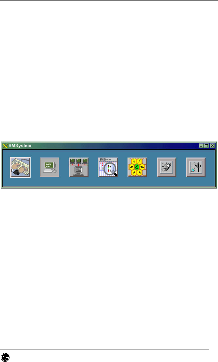
4.9.1. Manager Window.
4.9.1.1. Overview.
GUI manager window is the GUI main window managing GUI applications and
communicates with MMI block to exchange GUI information.
4.9.1.2. Operation.
Locate mouse indicator onto the button to display the name of corresponding
application; the pressed button means the corresponding application is on the run; the
application presently not on the run is presented as selectable button status.
4.9.1.3. Suggestions.
Fig. 4.9-1 Manager window
The MMI should be normally on the run because the manager is interworking with the
MMI block.
By accessing X-Window Pixmap file, the XPM file should exist in the XPM directory in
the run file directory, or else, ‘XPM open file Error!’ is displayed and all the block of
the GUI can not be run. Otherwise, if any program that use color palette such as
‘Netscape’ is running, it might not be run because it could not get the palette.
It is recommended using bitmap plane over 16bit to use GUI on the BSM.
4.9.2. Interm Window
4.9.2.1. Overview.
The interm is controlled by the manager; manages the user information and command
Input/Output.
STAREX-IS BSM Manual
Page:547(877)
Issue:1.
0
SMD-011-PMA210
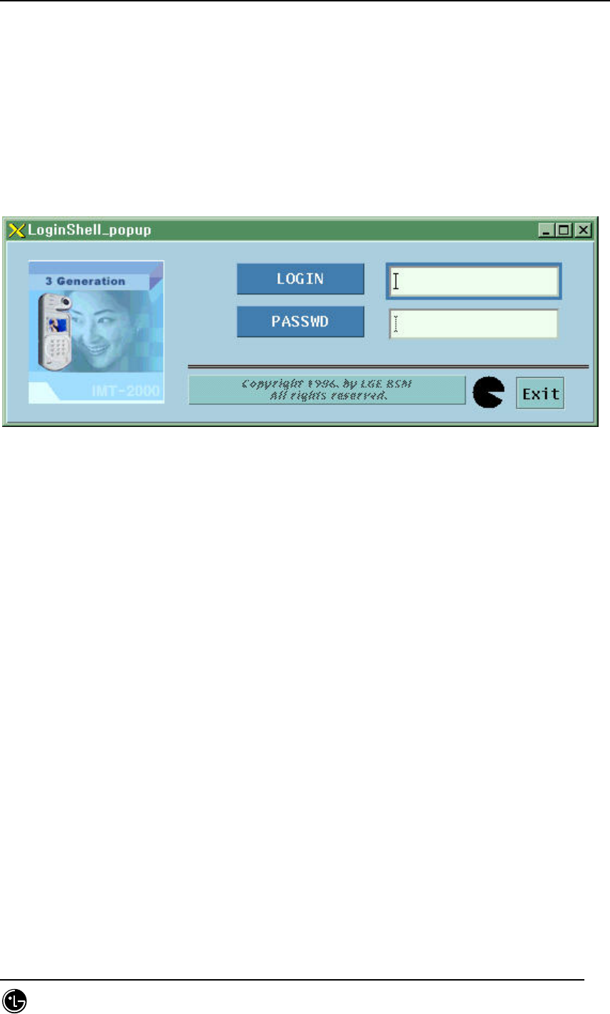
4.9.2.2. Login.
The login window is displayed as a initial screen and it gets input the user ID and
password. The user should finish the process in 1minute by entering the login ID and
password. If the password is not entered after entering the login ID the system
performs logout automatically to make the user unable to use the user command input
window.
Fig. 4.9-2 Login window.
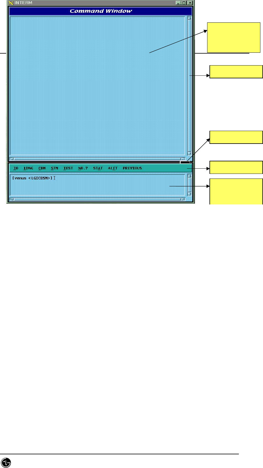
4.9.2.3. Window Configuration.
It is divided into command result display window, menu bar and command input
window; command processing time content is displayed on the window and
COMPLETED is displayed at the end of the display window.
The menu bar is consisted of commands into the following order: MMI related
command, Loading related command, configuration related command, status related
command, test related command, NO.7 related command, statistics related command,
alarm related command and PREVIOUS menu that execute the command previously
executed.
The prompt should be displayed on the screen in case the input window of lower part
is in standby status, and when the communication with CA of MMI is disconnected the
prompt is not displayed.
STAREX-IS BSM Manual
Page:548(877)
Issue:1.
0
SMD-011-PMA210
Fig. 4.9-3 Interm Configuration.
The line between the display window and the input window is a discriminator which
can adjust rate of input and display windows by dragging the button on the upper side
with mouse pointer. The display window by the command supports the popup menu to
adjust the display environment. It is divided into background color, text color, text font,
text size, and finish; press button 3 to pop up menu and then user can operate it. The
underlined letter in the pull down menu operation is the accelerator letter. Choosing
Meta + letter, the user can operate it immediately. If the user chooses the utmost part
with dotted line in the menu, the system offers Tear-Off function to operate menu
independently.
Command
Result Window
스크
롤
바
구분자
메뉴
바
명령어
입
력
창
Scroll Bar
Discriminator
Menu Bar
Command Input
Window
STAREX-IS BSM Manual
Page:549(877)
Issue:1.
0
SMD-011-PMA210
Fig. 4.9-4 CDM Tear-off
4.9.2.4. Operation Command and Usage.
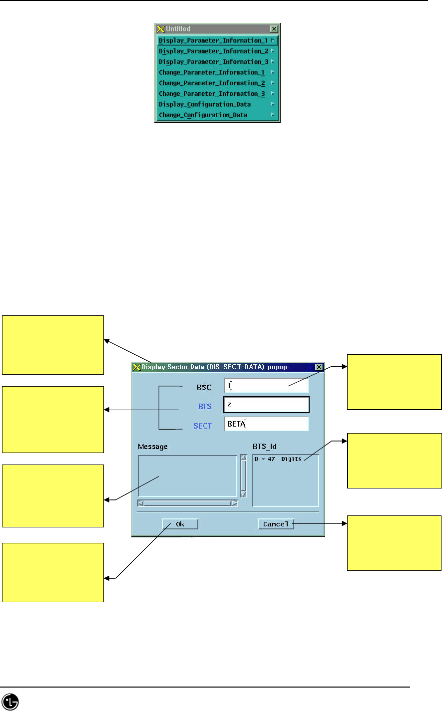
All commands are available in the pop-up menu with mouse as followed and also
available by inputting command manually on the INPUT WINDOW depending upon
command grammar like using shell command in UNIX.
4.9.2.4.1. Command Input Method using POP-UP MENU
Fig. 4.9-5 POP-UP window
Parameter
입력필드
사용자가
원하는
Parameter
의
값을
입력하는
창이다
Parameter
도움말
Parameter
의
유효값의
범위가
이창에
나타난다
Cancel Button
사용자가
이
작업을
취소
시키고자
할때
이
버튼을
누른다
Option Name
사용자가
입력할
옵션의
이
름으로
검정색은
반드시
입
력을
받아야하며
파랑색은
입력을
생략해도
된다
Message Display
Window-
The error message
appears here when invalid
parameter
value is input
Ok Button
사용자가
parameter
입력을
끝내고
작업을
수행하고자
할때
누른다
메뉴타이틀
사용자가
내린
명령어를
타이틀에
표시
해준다
Parameter Input Field
- Input parameter
value upon
user’s demand
Parameter Tip
-Valid parameter
value appears
Cancel Button
-Canceling the
operation by the user
Option
Name –
User’s input option name.
Black should be input Blue
one is can
be omitted
Ok Button-
When starting operation after
inputting parameter value
Menu Title - User
’s
command is on the title
STAREX-IS BSM Manual
Page:550(877)
Issue:1.
0
SMD-011-PMA210
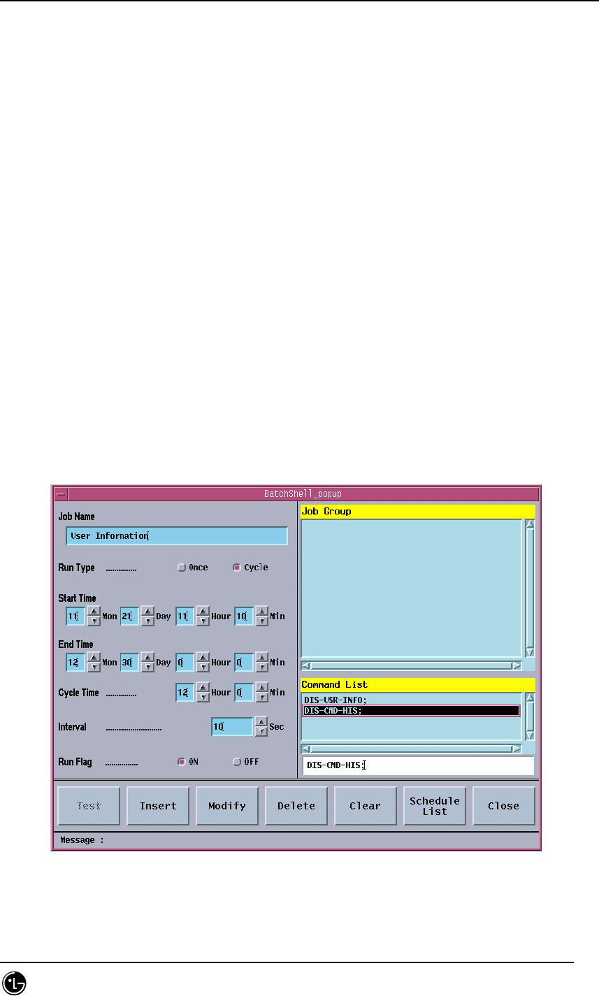
4.9.3. Batch Job
It is the function to make commands operate depending on the set value by reserving
the MMC at the user’s definition for the user’s convenience.
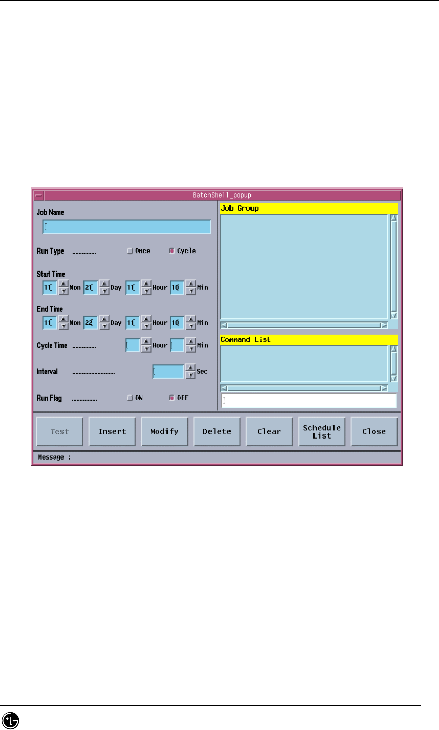
4.9.3.1. Batch Job Window Configuration
The window is divided into the following three parts by the characteristics of the
work: batch job set part, batch job list and command list, menu part.
Fig. 4.9-6 Batch Job Screen
4.9.3.2. Run Batch Job
The batch job menu is included in the IO sub-menu, and just one batch job can be
executed in one workstation. If the batch job is authorized, the menu is displayed in
the executable status; if the batch job is already under execution the system prevents
the overlapping of the work by making the menu ‘Disable’. That is, the menu can be
run on the interm run with bim; the menu always is ‘Disable’ upon remote access using
telnet or rlogin; the menu can be run upon client access using the pcsnet because it
uses local DB.

STAREX-IS BSM Manual
Page:551(877)
Issue:1.
0
SMD-011-PMA210
.
4.9.3.3. Batch Processing Set Area
Job Name
It is the name of the work to be set and added into the Job Group when storing. The
maximum length of the name is restricted into 40 letters.
Run Type
Set if the work to be operated with a cycle, or at the specific time. (ONCE, CYCLE)
Start Time
It is the starting time of the work and the present time of the system is filled in the
data field as a basic value.
End Time
It is the ending time of the work and the next date for the present time of the system
is filled in the data field as a basic value. If the ending time has passed the present
time it takes the Run Flag off.
Cycle Time
It designates the hour and minute to execute the next command when the Run Type is
set as Cycle.
Interval
It is the time between each command represented in seconds (1~6000) when several
commands are input in single work name. Interval over 5sec is recommended.
Run Flag
It represents whether the set batch processing is executed. (ON, OFF)
List Area
Job Group
It is the list of registered works and the key value, which controls DB.
Command List
It is the list of commands for single work. Maximum four commands can be input.
Command Input Text Field
It is the field on which the command is input.
4.9.3.4. Menu Field
Test
It is the menu to test if the command for the presently selected work or the work for
which the input is performed is input without error.
Insert

STAREX-IS BSM Manual
Page:552(877)
Issue:1.
0
SMD-011-PMA210
It is the menu to input new work.

STAREX-IS BSM Manual
Page:553(877)
Issue:1.
0
SMD-011-PMA210
Modify
It is the menu to modify the previously input work.
Delete
It is the menu to delete the input work or the command in the command list.
Clear
It is the menu to remove the values left in the data field.
Schedule List/Setup Screen
It shows the schedule list presently on the execution standby status.
Exit/Close
It is the menu to close the batch job window.
4.9.3.5. Message Display Area
Error message on operation and messages for alarm and status change are displayed.
STAREX-IS BSM Manual
Page:554(877)
Issue:1.
0
SMD-011-PMA210
4.9.3.6. Batch Job Operation
4.9.3.6.1. Open Window
Select IO menu of “INTERM”, which is command I/O window, and click Batch Job then
the window is opened.
4.9.3.6.2. Job Input
Job name is the key value that controls DB so it should be the one and only value.
When selecting insert menu it would not be stored unless the job name is input. The
data field restricts the number of letters when inputting the data; emits alarm sound
when it is exceeded. The figure input part is configured with the field in which the
figure can be input manually and the buttons that change the figures. The maximum
and minimum value is designated so if the figure exceeds this scope, it is set as a
minimum value; if a letter is input the system emits alarm sound. After one command is
input in the command input field, press ‘Enter’ key then it added into the command list.
If a wrong command is added, select the list and press ‘Delete’ menu then it will be
deleted.
Fig. 4.9-7 Batch Job Input

STAREX-IS BSM Manual
Page:555(877)
Issue:1.
0
SMD-011-PMA210
After the input is completed, check if it is set with correct values and choose ‘Insert’
menu.
STAREX-IS BSM Manual
Page:556(877)
Issue:1.
0
SMD-011-PMA210
4.9.3.6.3. Job Modifying
The job modification takes the same method with the input but the job name operates
the key of DB cannot be modified.
Fig. 4.9-8 Batch Job Modification
After modifying, input ‘Modify’ menu by all means, so as that the modification is
completed.
4.9.3.6.4. Job Deletion
Use ‘Delete’ menu with great care because it has two functions: deleting job group and
deleting command list. Choose ‘Delete’ menu after selecting job group list then the
chosen job will be deleted; press ‘Delete’ menu after selecting command group then
the command will be deleted. Choose ‘Modify’ once more when deleting command so
as to delete the command completely and store the content into the DB.
STAREX-IS BSM Manual
Page:557(877)
Issue:1.
0
SMD-011-PMA210
Fig. 4.9-9 Batch Job Deletion
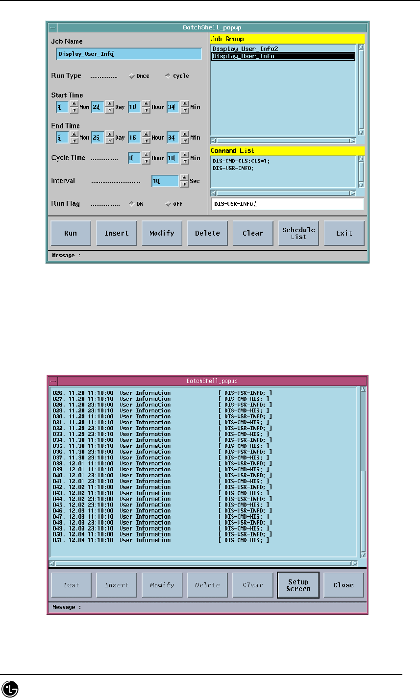
4.9.3.6.5. Job Status Display
This menu shows the set jobs with their schedule. This menu shows setup window and
schedule list by converting them with toggle method.
Fig. 4.9-10 Batch Job Status Display
STAREX-IS BSM Manual
Page:558(877)
Issue:1.
0
SMD-011-PMA210
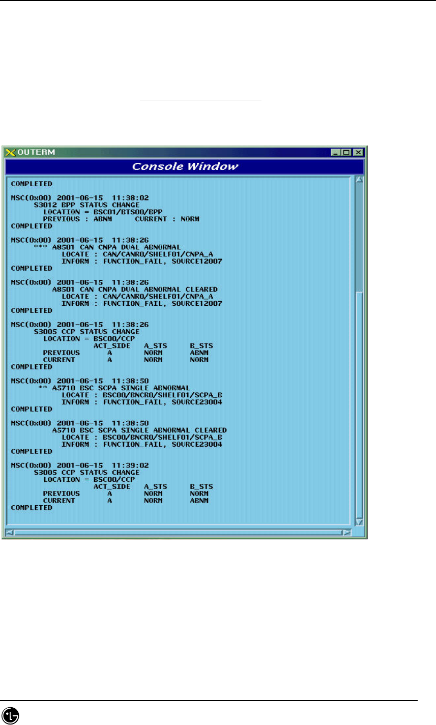
4.9.4. Console Window
4.9.4.1. Overview
It is the window displaying event list of processor and also displays status change
alarm and alarm information.
Fig. 4.9-11 Console Window
4.9.4.2. Operation
The console window displays system message, supports pop-up menu and its display
environment is adjustable. It is divided into background color, text color, text font, text
STAREX-IS BSM Manual
Page:559(877)
Issue:1.
0
SMD-011-PMA210
size and close; press mouse button 3 to operate this function then the operating menu
pops up. The number of message to be displayed is uncertain depending upon system
load but roughly 400 through 800 messages can be displayed per second.
4.9.5. Controller
4.9.5.1. Overview
As the GUI gets complicated and varied the control for GUI is needed. Therefore,
place a controller to control the entire GUI with close relation to their connection.
Furthermore, due to the supply of network environment the user can access to a
system more easily; the control is more complicated; monitor equipment to monitor
and control them is needed; so the equipment to control the network and message
display is developed.
The controller manages the host accessing to BMS Server; controls the display
message of BSC, BTS, and Message Type; is in charge of process management.
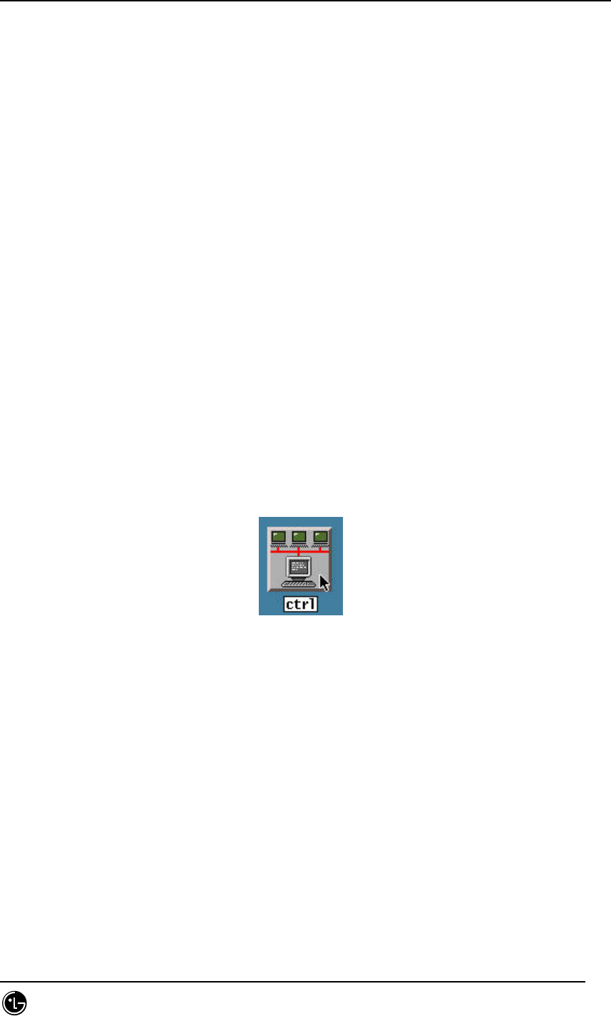
4.9.5.2. Operation
Press ctrl among the buttons in Manager to start operation.
Fig. 4.9-12 ctrl Start Icon
Then the following screen is displayed.
The controller is divided into two parts of network control and message control.
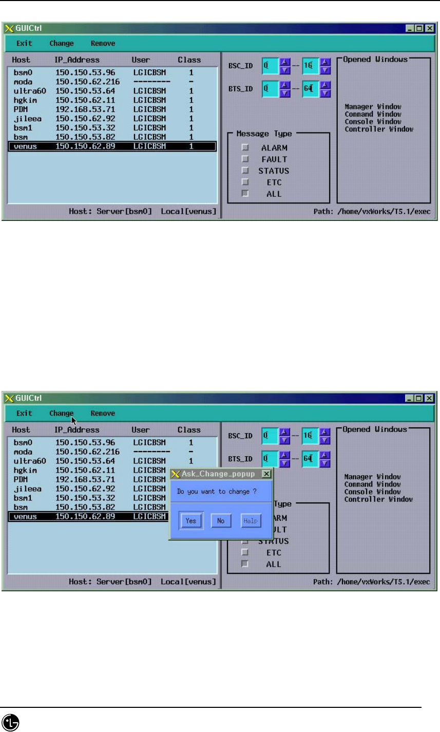
STAREX-IS BSM Manual
Page:560(877)
Issue:1.
0
SMD-011-PMA210
Fig. 4.9-13 Controller Window
4.9.5.3. Message Filtering
The message control function is only supplied to the host, and it can filter and display
the message of particular BTS or specific part. The message type is sorted into
ALARM, FAULT, STATUS, and ETC. If the message type is not defined display the ‘all
message display’.
Fig. 4.9-14 Message Filtering of Controller
4.9.5.4. Network Management
The network control is the function provided by the BMS server and supplies the
following functions: checking the host name of presently accessed client, address, user,
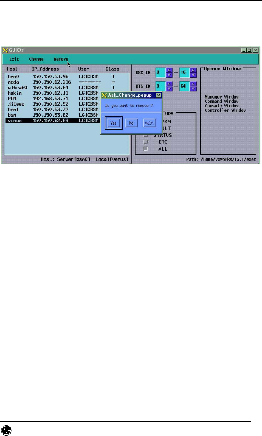
STAREX-IS BSM Manual
Page:561(877)
Issue:1.
0
SMD-011-PMA210
user’s grade, and message display information and compulsory expulsion of them. The
client can display the hosts presently in operation but cannot control the other users
except its host.
Fig. 4.9-15 Network Management of Controller
4.9.5.5. Suggestions
This program refers to the /etc/hosts file, so IP_Address, Domain_name, and
Alais_name should be correctly recorded fit for the network configuration information.
4.9.6. Status Window (stmGUI)
4.9.6.1. Overview
The user can use the MMC (DIS-*-STS, DIS-*-ALM, DIS-*-FLT) to investigate the
status of processor, board and alarm occurrence in each BSC/BTS. However, the user
should keep on inputting commands with keyboard or mouse to check it on real-time;
moreover, it is hard for the user to grasp the whole situation at one sight; therefore,
the system takes advantage of the GUI(Graphic User Interface) to help the user in
operation and for the more efficient system management.
4.9.6.2. Environment Setup
Solaris 2.7 and CDE library are used to develop the BMS as the OS and Graphic library.
Moreover the Window Manager is set to be performed under CDE (Common Desktop
Environment). Therefore, the user would be in a good operational environment if he
operates the system on the environmental ground above (refer to the set and

STAREX-IS BSM Manual
Page:562(877)
Issue:1.
0
SMD-011-PMA210
environment set).

STAREX-IS BSM Manual
Page:563(877)
Issue:1.
0
SMD-011-PMA210
4.9.6.2.1. Suggestions
LD_LIBRARY_PATH is one of the most important environment variables. The stmGUI
could be down during the operation unless the user let the stmGUI search
/usr/X11R5/lib first of all.
e.g.) setenv LD_LIBRARY_PATH /usr/dt/lib/:usr/openwin/lib/:/usr/lib
4.9.6.2.2. Data Files
If the stmGUI is unable to be run, the needed data files could be non-existed.
Therefore, check if the following files are in the DATA/GUI Directory.
RACK.DAT : file contains the shape of RACK .
SHELF.DAT : file contains the shape of SHELF.
PROCESS.DAT: definition file of the processors.
*.xpm : drawing files needed in screen processing.
bts_name.info : files contain BTS name.