LG Electronics USA 3G1XOUTBTS STAREX-IS 1900 Outdoor BTS User Manual STAREX IS User s Manual
LG Electronics USA STAREX-IS 1900 Outdoor BTS STAREX IS User s Manual
Contents
- 1. Users Manual Part 1
- 2. Users Manual Part 2
- 3. Users Manual Part 3
- 4. Users Manual Part 4
- 5. Users Manual Part 5
Users Manual Part 3
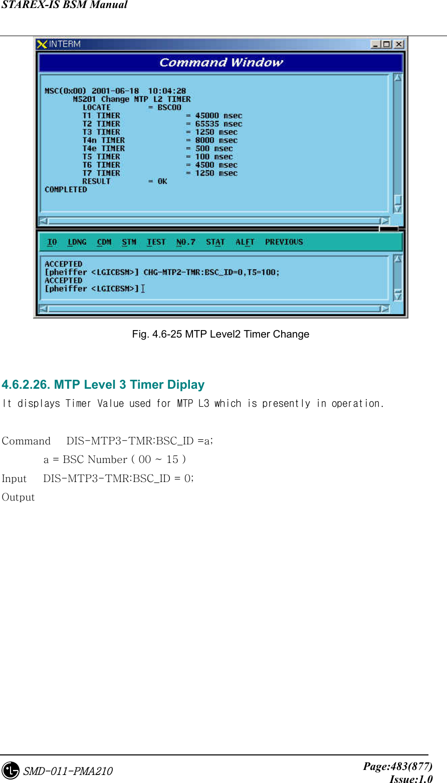
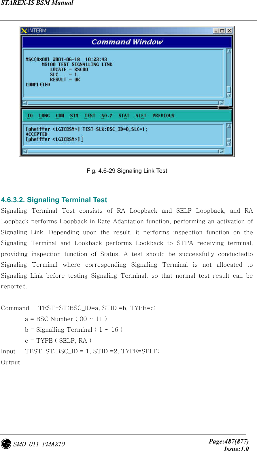
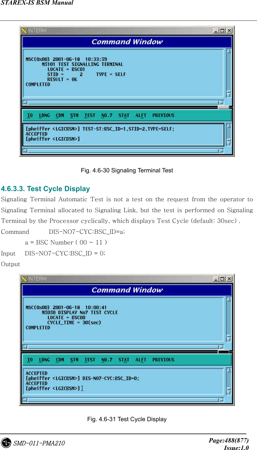
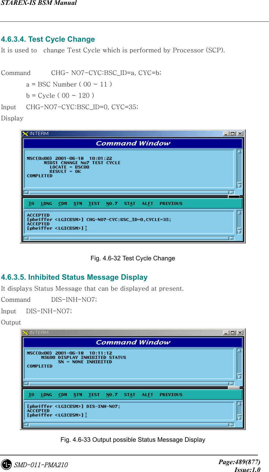
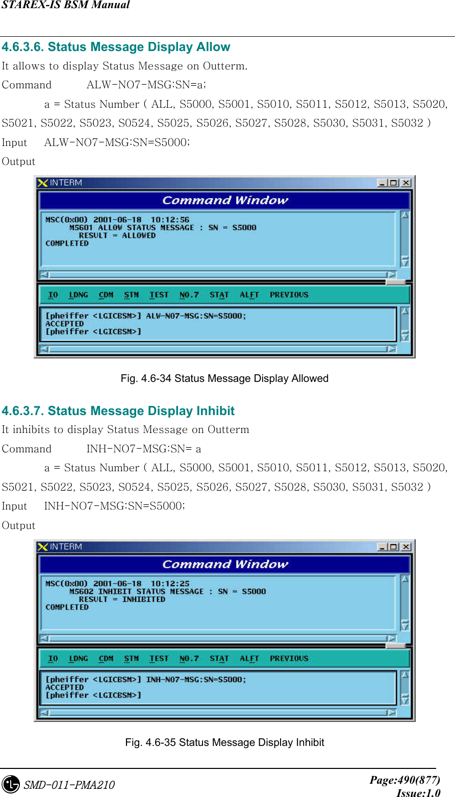
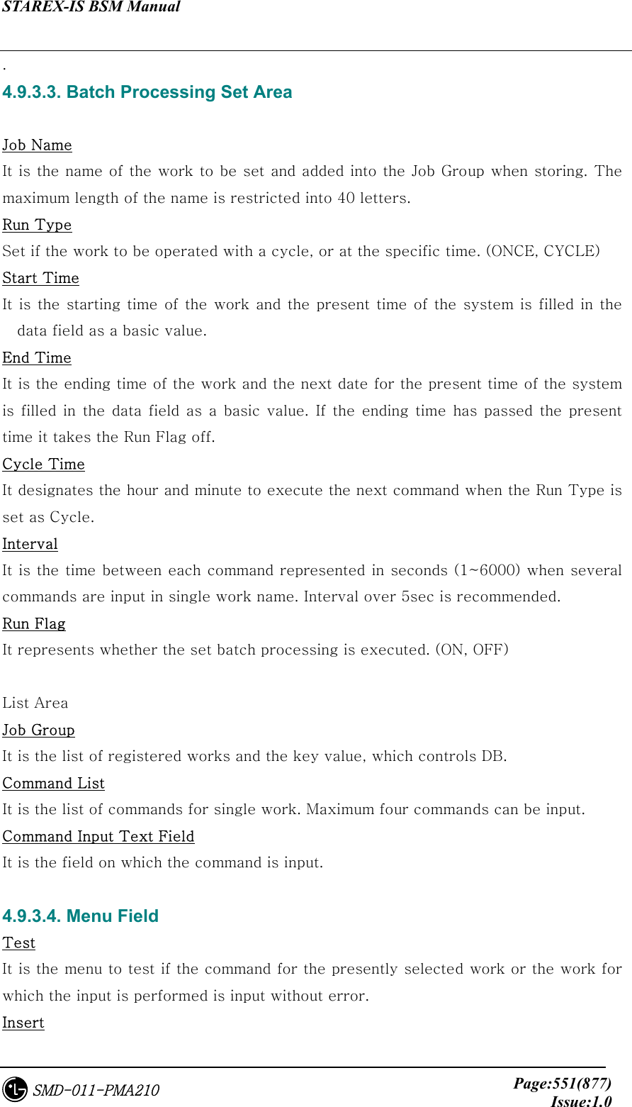
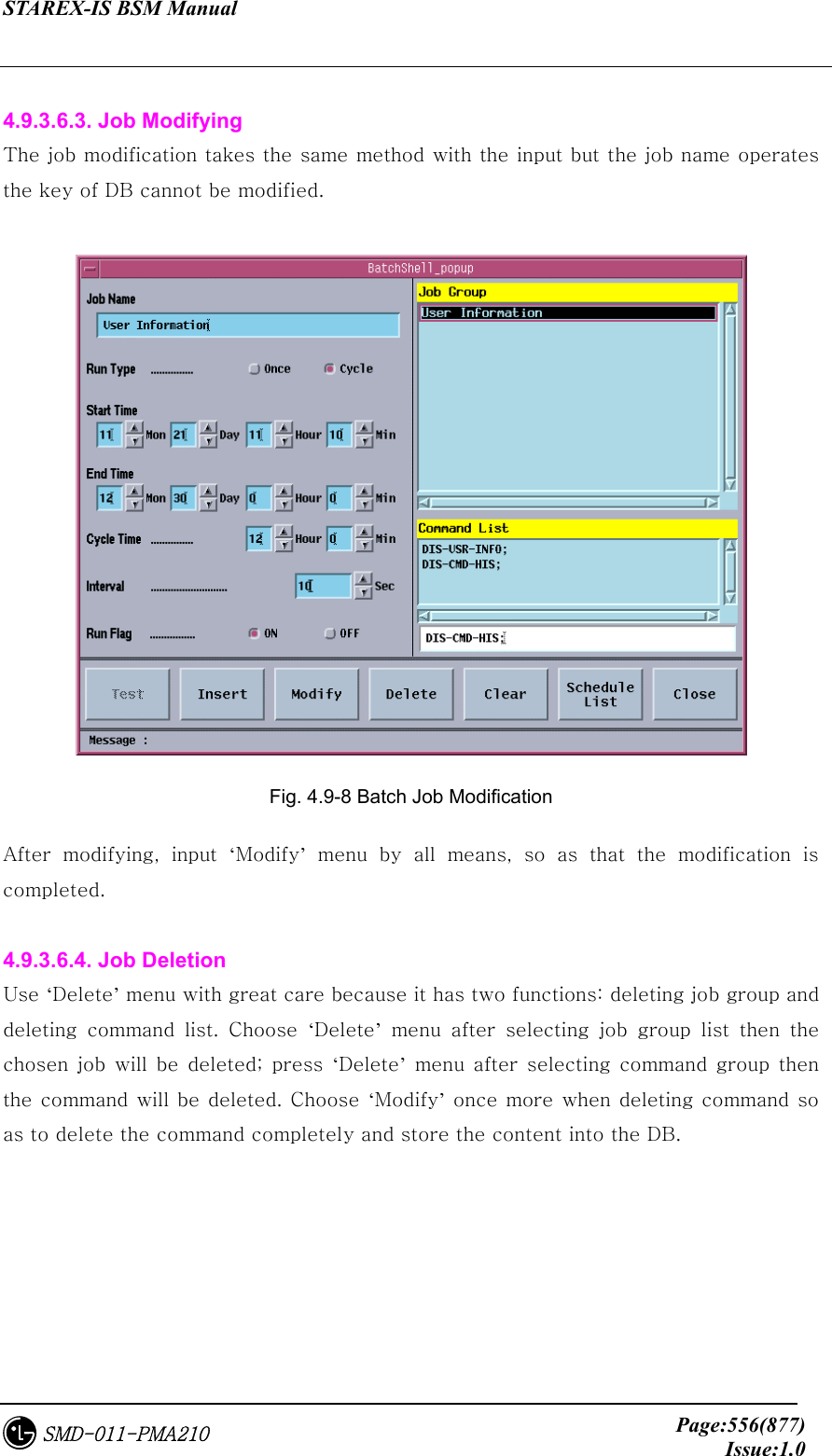
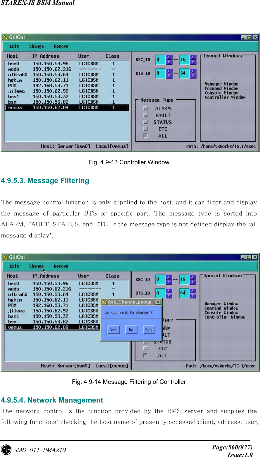
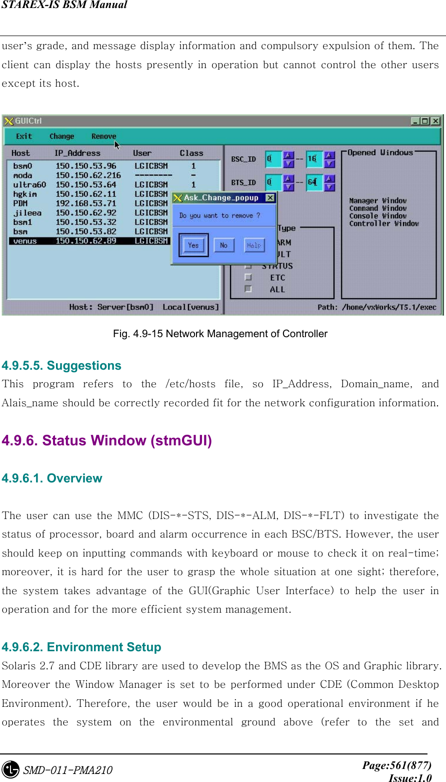
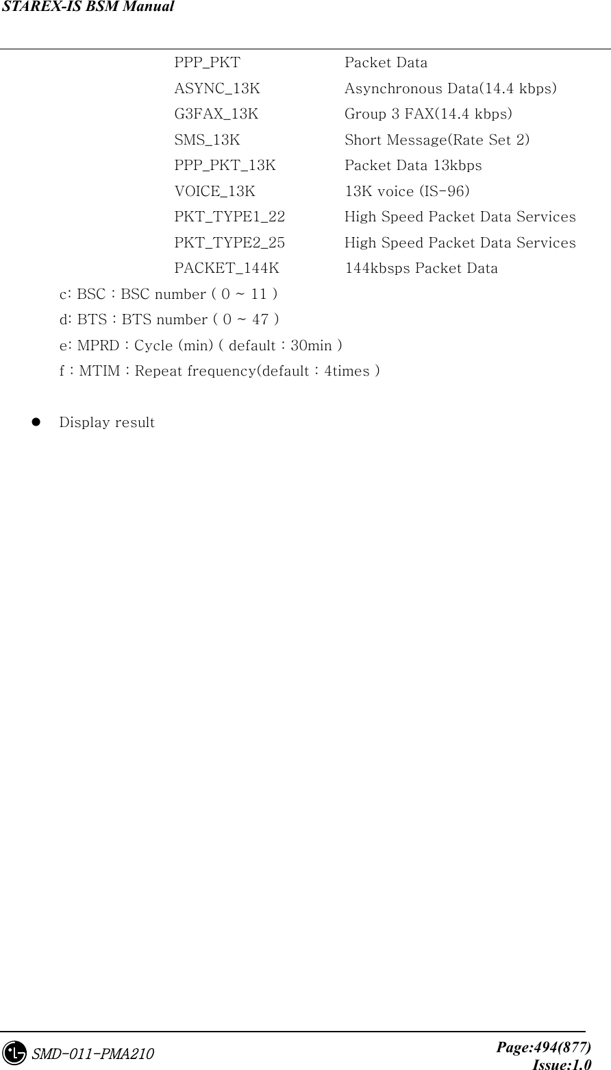
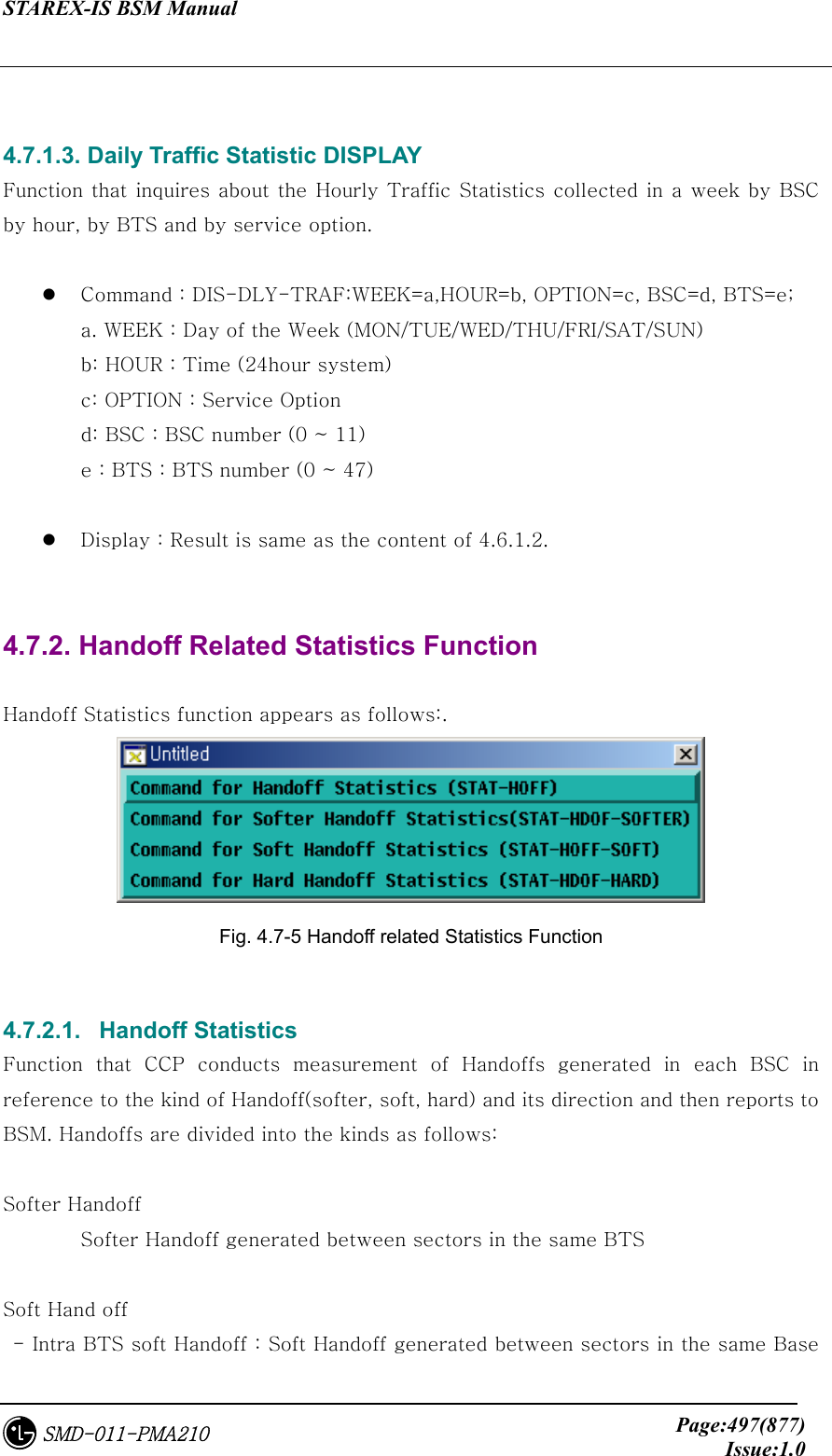
![STAREX-IS BSM Manual Page:491(877)Issue:1.0SMD-011-PMA210 4.7. Statistics Command Apart from switching system, statistics Function in BSM measures performance and load and reports them to NMS(Network Management System), a center for self-reporting and network management. The function of statistics is divided logistically into three. The first one is that On Demand statistics items that the user measures designated statistics item and BTS on the arbitrary time for the specific cycles. And additionally to be included is Hourly Statistic that collects, without complying with the user’s request, all the statistics always on time for reporting to NMS. Lastly, it is divided into On Line Statistics that collects and sends statistics every 5 minutes so that NMS can confirm on a real time basis. The following commands in series are mainly related to On Demand Statistics, and Hourly Statistics function was configured, in consideration of BMS performance to display on request only from user. On Demand Statistics function is used only when the user wants to check performance related data with specific BSC or BTS. For Hourly Statistics function, once statistics report is requestedto CCP, BSP, PCP, NCP and CNP that are major processors at every fixed time, all kinds of statistics collected are gathered at the corresponding processor and transferred. Section between BSM and BSS are connected to STM-1, but because the volumes of the collected statistics are so huge that they are executed for 15 minutes. That is, the report of statistics data to NMS is made at 15 minutes after the every hour. BSM becomes to keep hourly statistics data. Storages are made on an hourly basis for a week and are stored in binary in PKG/DATA/STAT/HOURLY. Reports to NMS are made by the reporting method of ASCII and the method providing Binary and Library at the user’s request. Table 4.7-1 Statistics Command List Division Content Statistics Commands Traffic STAT-TRAF:DIR=a,OPTION=b,BSC=c,BTS=d [,MPRD=e, MTIM=f]; Hourly Traffic DIS-HLY-TRAF:HOUR=a,OPTION=b,BSC=c,BTS=d; Traffic Related Daily Traffic DIS-DLY-TRAF:WEEK=a,HOUR=b,OPTION=c,BSC=d,BTS=e; Hand off (all) STAT-HOFF:BSC=a,BTS=b[,MPRD=c, MTIM=d]; Hand off Related Softer Handoff STAT-HOFF-SOFTER:BSC=a[,BTS=b,MPRD=c, MTIM=d];](https://usermanual.wiki/LG-Electronics-USA/3G1XOUTBTS.Users-Manual-Part-3/User-Guide-178515-Page-13.png)
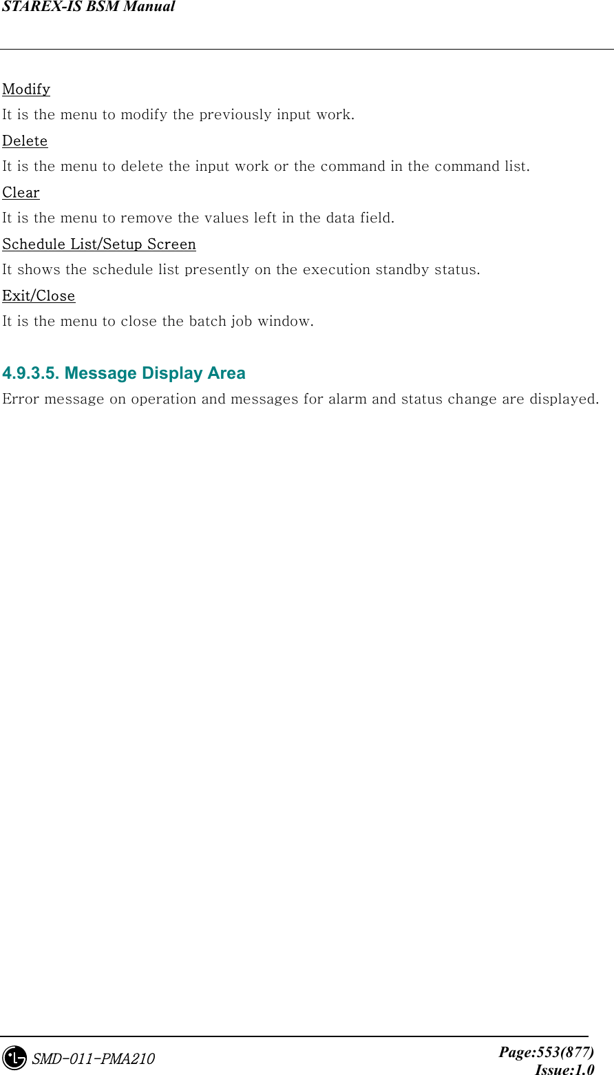
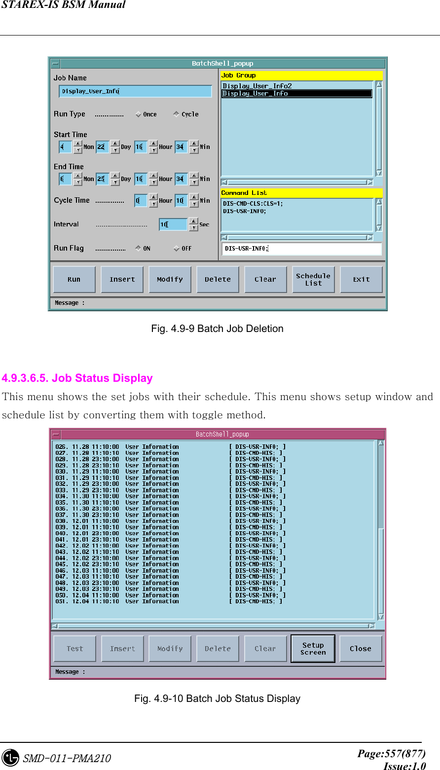
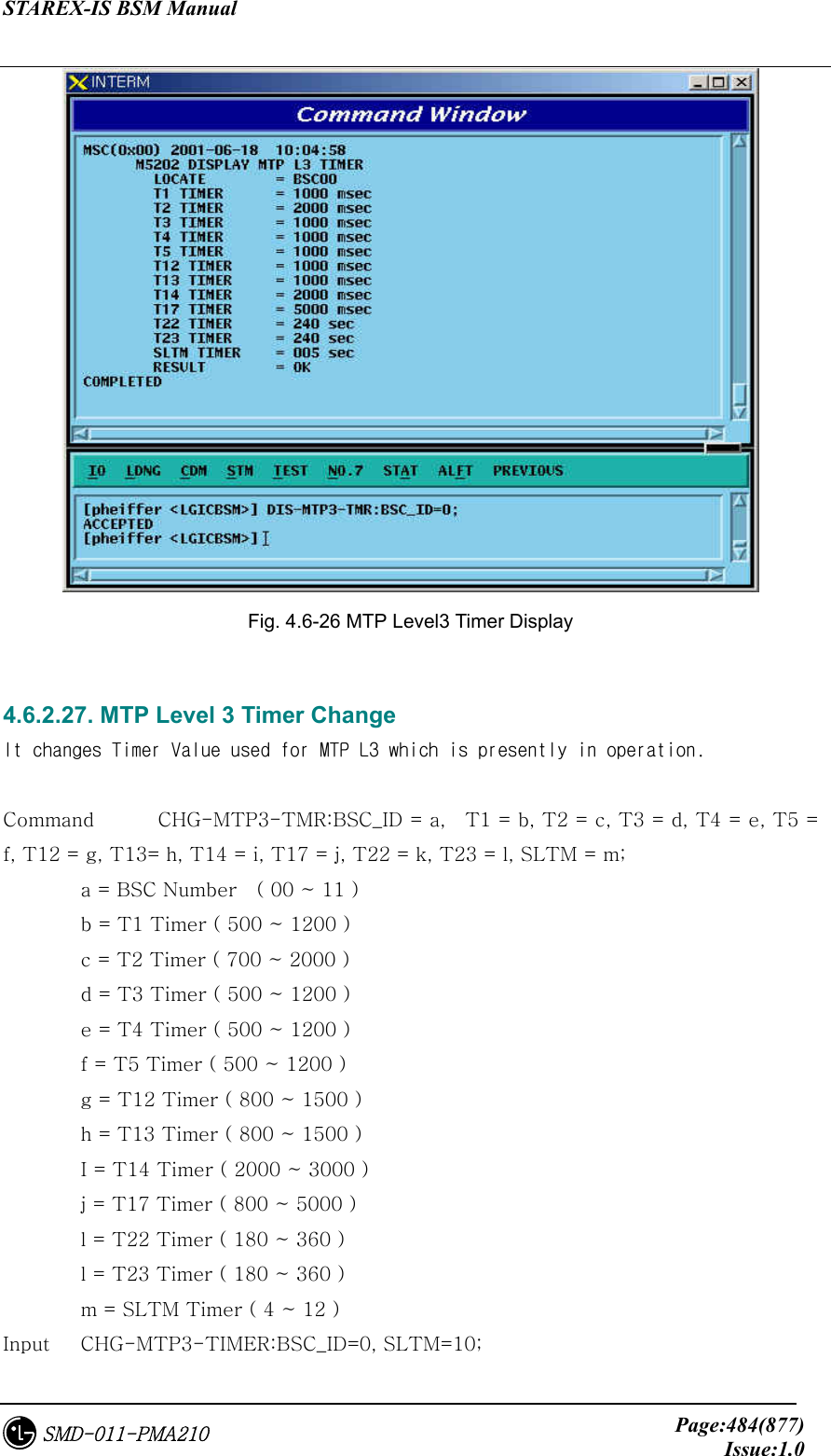
![STAREX-IS BSM Manual Page:492(877)Issue:1.0SMD-011-PMA210 Soft Handoff STAT-HOFF-SOFT:BSC=a[,BTS=b,MPRD=c, MTIM=d]; Hard Handoff STAT-HOFF-HARD:BSC=a[,BTS=b,MPRD=c, MTIM=d]; Channel Element STAT-CE:BSC=a[,BTS=b,MPRD=c, MTIM=d]; Vocoder STAT-VOC:BSC=a,VMP=b[,VCP=c,MPRD=d, MTIM=e]; Network STAT-NET:CAN=a,BSC=b[,BTS=c,ITEM=d,MPRD=d,MTIM=e]; Radio Channel STAT-CH:BSC=a[,BTS=b,MPRD=c,MTIM=e]; Processor STAT-PRC:CAN=a,BSC=b[,BTS=c,MPRD=d,MTIM=e]; Selector STAT-SLT:BSC=a,SMP=b[,SLP=c,MPRD=d,MTIM=e]; BTS Performance STAT-PERF:BSC=a[,BTS=b,MPRD=c,MTIM=d]; Paging STAT-PAGE:BSC=a[,BTS=b,MPRD=c,MTIM=d]; CAI Signaling STAT-CAI:ITEM=a,BSC=b[,BTS=c,MPRD=d, MTIM=e]; NO7 STAT-NO7:ITEM=a,SCP=b[,MPRD=c,MTIM=d]; Round Trip Delay STAT-RTD:BSC=a,BTS=b[,MPRD=c,MTIM=d]; Call Related RF Min/Max STAT-RF:BSC=a,BTS=b,ITEM=c[,MPRD=d,MTIM=e]; Packet Data STAT-PKD:PCP=a,SHELF=b[,PIP=c,MPRD=d,MTIM=e]; Packet Control STAT-PKC:PCP=a[,MPRD=b, MTIM=c]; Packet Related Packet Handoff STAT-PCP:PCP=a[,MPRD=b, MTIM=c]; Statistic List DIS-STAT-ITEM; Statistics Job DIS-STAT-JOB; Statistics Stop CAN-STAT:[BSC=a,]JOB=b; Hourly Statistic Display DIS-HLY-DATA:HOUR=a,ITEM=b,BSC=c[,BTS=d]; Daily Statistics Display DIS-DLY-DATA:WEEK=a,HOUR=b,ITEM=c,BSC=d[,BTS=e]; Others Online Cycle Change CHG=ONLINE-MPRD[:MPRD=a]; Display of Hourly/Daily Statistics for the same item of statistics is identical to On Demand Statistics. It is not related to Processor or Device that measures and reports statistics, but is related only to equip of PLD. This function of statistics is consisted of 5 Categories to include Traffic, Handoff, Call related, Packet related and others, and in the window of user’s command the following is displayed.](https://usermanual.wiki/LG-Electronics-USA/3G1XOUTBTS.Users-Manual-Part-3/User-Guide-178515-Page-14.png)
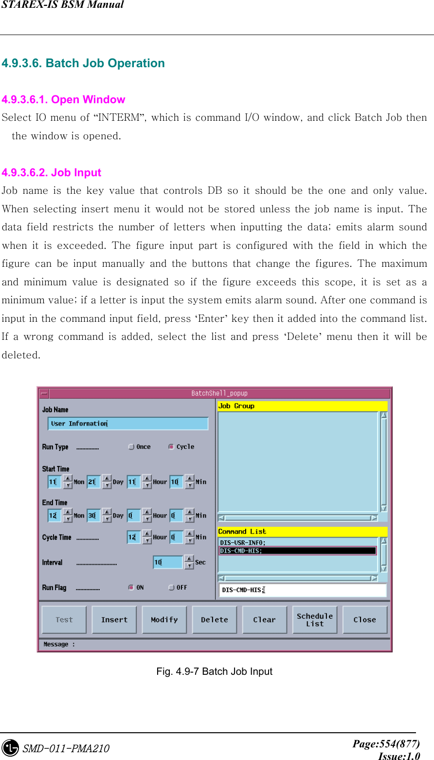
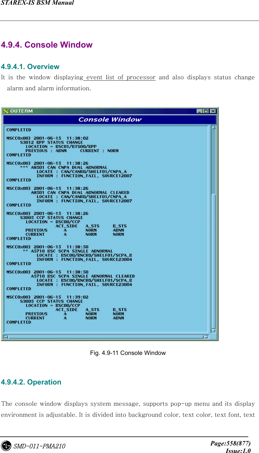
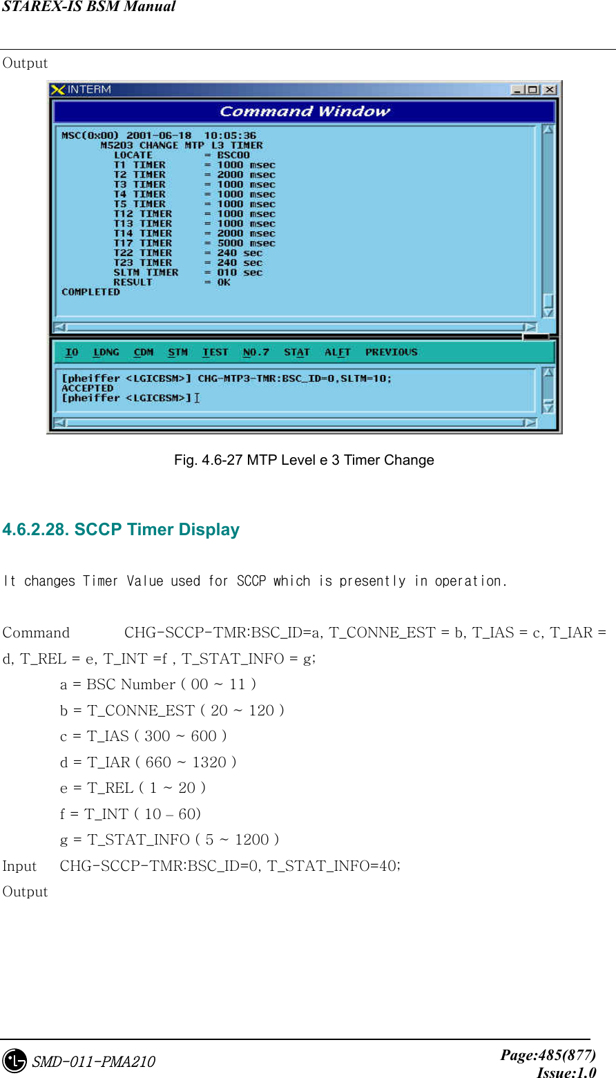
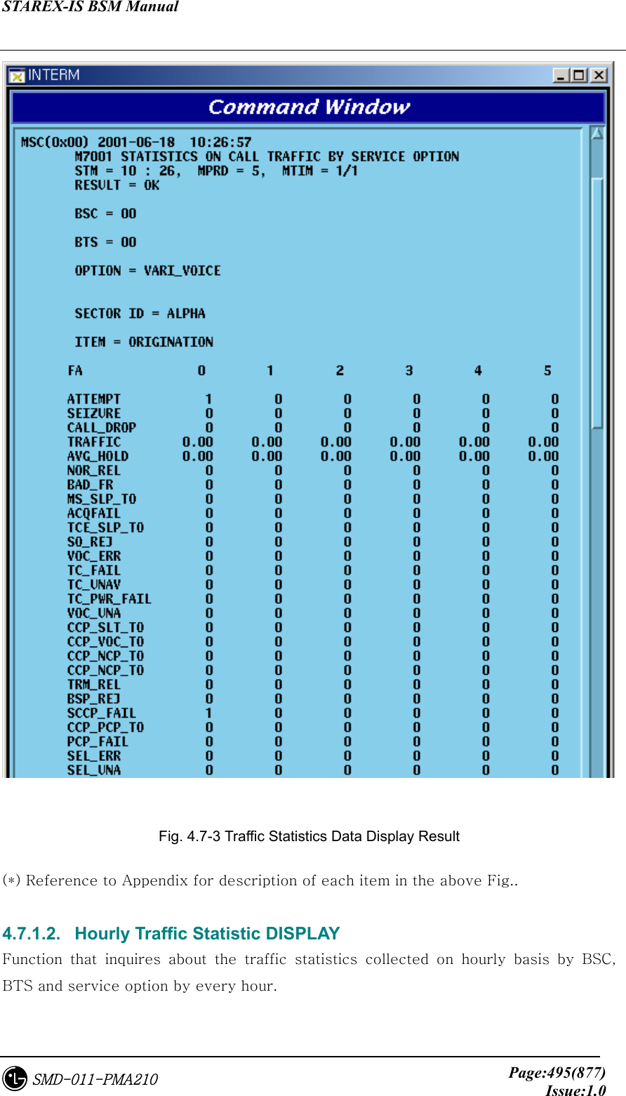
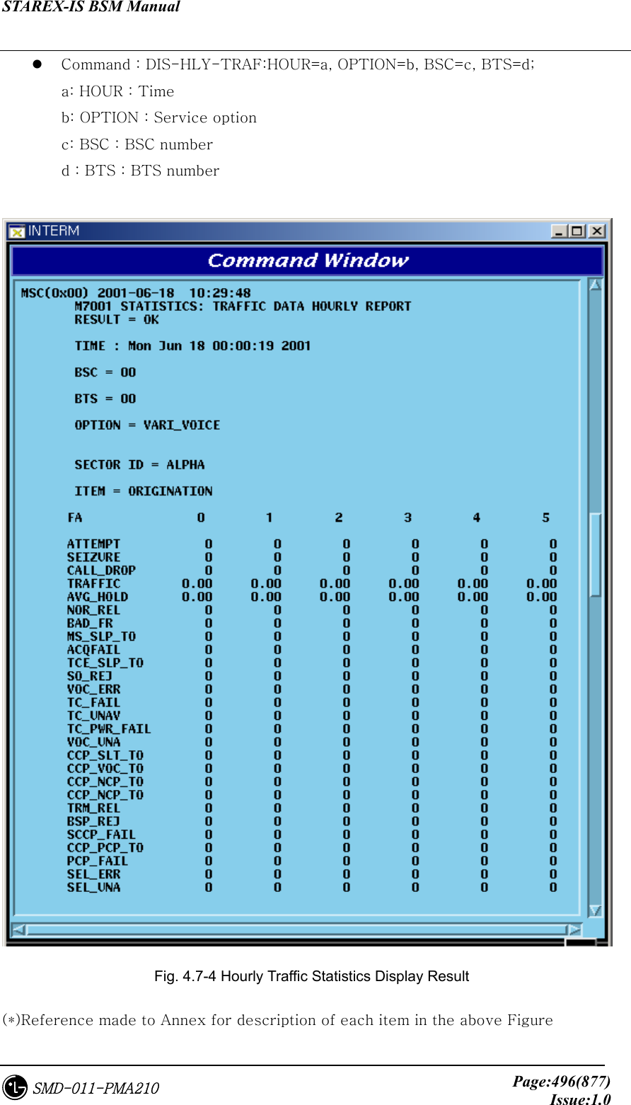
![STAREX-IS BSM Manual Page:493(877)Issue:1.0SMD-011-PMA210 Fig. 4.7-1 Configuration of Statistics Command 4.7.1. Traffic related Statistics Command Traffic Statistics is differentiated as follows: Fig. 4.7-2 Traffic Statistics Function 4.7.1.1. Traffic Statistics by Service Option This is a function which for originating call and terminating call, reports and displays the number of attempt by service option, number of success, number of failure and the collected content by reason of a failure by CCP to BSM, and for Statistics Data, collection is made by the separated each item of Service Option/Direction/ BSC/BTS/FA/SECTOR.. Command : STAT-TRAF:DIR=a,OPTION=b,BSC=c,BTS=d[,MPRD=e,MTIM=f]; a : DIR : ALL – Measuring all of originating calls and terminating calls ORG – Measuring originating only TRM – Measuring terminating call only b: OPTION : VOICE 8K voice VARI_VOICE 8K EVRC ASYNC Asynchronous Data(9.6 kbps) G3FAX Group 3 FAX(9.6 Kbps) SMS Short Message Service](https://usermanual.wiki/LG-Electronics-USA/3G1XOUTBTS.Users-Manual-Part-3/User-Guide-178515-Page-15.png)
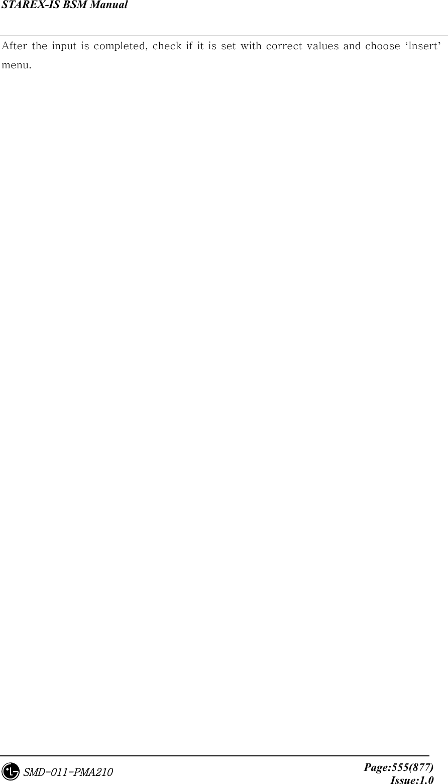
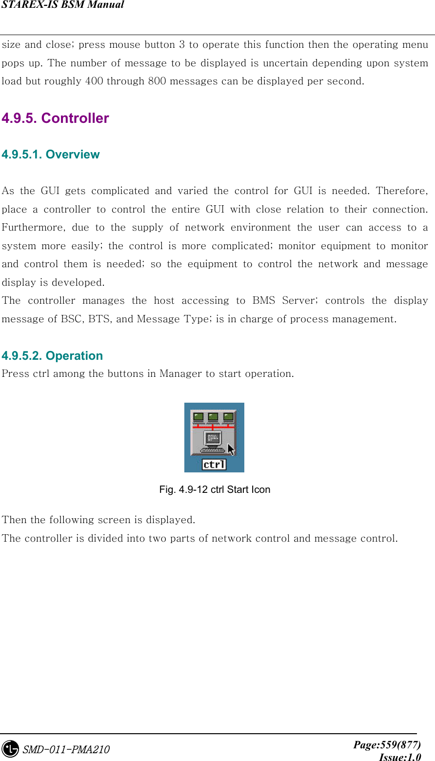
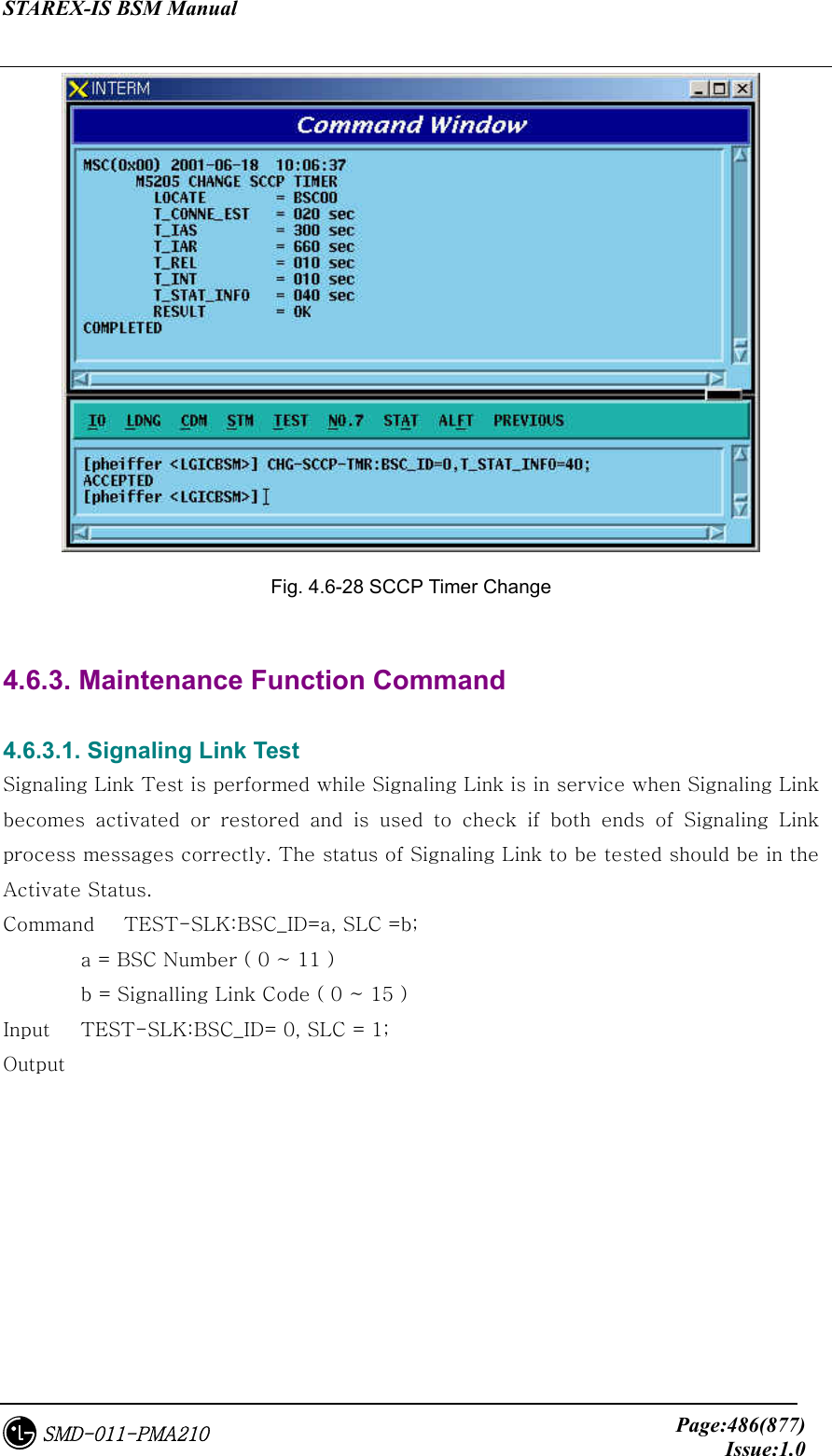
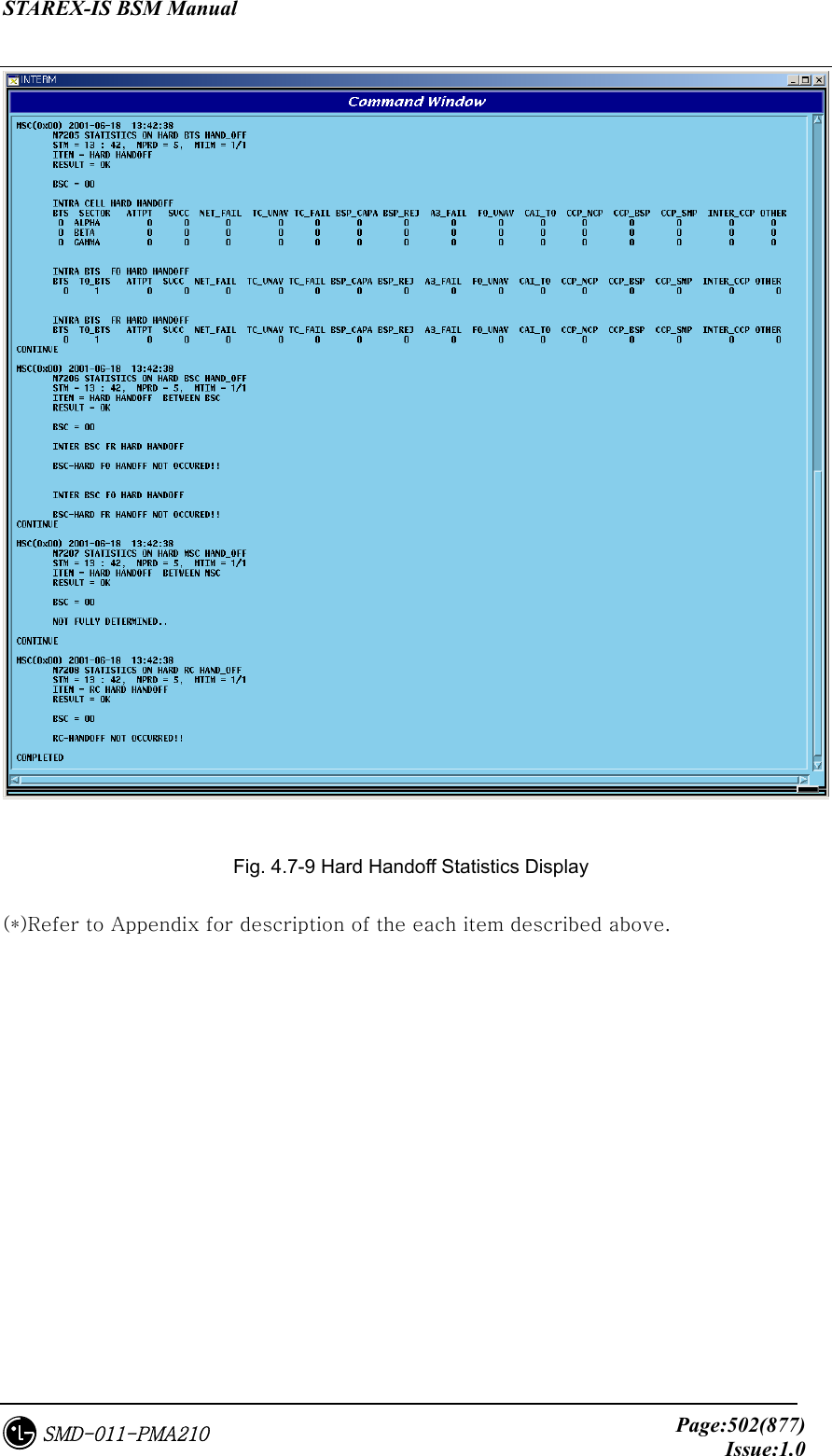
![STAREX-IS BSM Manual Page:498(877)Issue:1.0SMD-011-PMA210 Station - Intra BSC Soft Handoff : Soft Handoff generated between the same BSCs - Inter MSC Soft Handoff : Soft Handoff generated between other BSCs Hard Hand off - Intra Cell Hard Handoff : Hard Handoff generated by frequency change in the same BTS - Intra BSC FR Hard Handoff : Hard Handoff generated by frequency change between BTSs of the same BSC - Intra BSC FO Hard Handoff : Hard Handoff generated by Frame offset between BTSs of the same BSC - Inter BSC FR Hard Handoff : Hard Handoff by frequency change generated between BTSs of other BSCs - Inter BSC FO Hard Handoff : Hard Handoff by the change of Frame offset generated between BTSs of other BSCs - Hard Hand off between RCs : Handoff generated between RCs Command : STAT-HOFFF:BSC=a, BTS=b[,MPRD=c,MTIM=d]; a : BSC : BSC number ( 0 ~ 11) b : BTS : BTS number ( 0 ~ 47 ) c : Cycle(minute) : Default 30min d : Repetition Frequency : Default 4 times Display :](https://usermanual.wiki/LG-Electronics-USA/3G1XOUTBTS.Users-Manual-Part-3/User-Guide-178515-Page-20.png)
![STAREX-IS BSM Manual Page:499(877)Issue:1.0SMD-011-PMA210 Fig. 4.7-6 Handoff Statistics (*)This Command(STAT-HOFF) displays all kinds of Handoff. Refer to Appendix for each item. 4.7.2.2. Softer Handoff Statistics It collects by collected item (refer to Appendix) the soft Handoff generated between sectors in the same BTS and displays. Command : STAT-HOFF-SOFTER:BSC=a, BTS=b[,MPRD=d, MTIM=d]; a : BSC : BSC number ( 0 ~ 11) b : BTS : BTS number ( 0 ~ 47 ) c : MPRD : Cycle(min) : Default 30min d : MTIM : Repetition number : Default 4times Display](https://usermanual.wiki/LG-Electronics-USA/3G1XOUTBTS.Users-Manual-Part-3/User-Guide-178515-Page-21.png)
![STAREX-IS BSM Manual Page:500(877)Issue:1.0SMD-011-PMA210 Fig. 4.7-7 Softer Handoff Statistics Display (*)Refer to Appendix for each item described above. 4.7.2.3. Soft Handoff Statistics It measures for display the soft Handoff generated between sectors of the same BTS, in the internal part of the same BSC, or in other BSC. Command : STAT-HOFF-SOFT:BSC=a[,BTS=b, MPRD=c, MTIM=d]; a : BSC : BSC number ( 0 ~ 11 ) b : BTS : BTS number ( 0 ~ 47 ) c : Cycle(min) : Default 30min d : Repetition Frequency : Default 4times Display](https://usermanual.wiki/LG-Electronics-USA/3G1XOUTBTS.Users-Manual-Part-3/User-Guide-178515-Page-22.png)
![STAREX-IS BSM Manual Page:501(877)Issue:1.0SMD-011-PMA210 Fig. 4.7-8 Soft Handoff Display Result (*) Refer to Appendix for description of the items above. 4.7.2.4. Hard Handoff Statistics It is statistics to be measured in CCP for Hard Handoff between BSCs, such as Handoff followed by frequency change between the same BTSs and Handoff generated in the same BSC, and Hard Handoff generated between RCs. Command : STAT-HOFF-HARD:BSC=a,BTS=b[,MPRD=c,MTIM=d]; a : BSC : BSC ( 0 ~ 11 ) b : BTS : BTS ( 0 ~ 47 ) c : MPRD : Cycle(min) : Default 30min d : MTIM : Number of Frequency : Default 4times](https://usermanual.wiki/LG-Electronics-USA/3G1XOUTBTS.Users-Manual-Part-3/User-Guide-178515-Page-23.png)
![STAREX-IS BSM Manual Page:503(877)Issue:1.0SMD-011-PMA210 4.7.3. Call Related Statistics Function Statistics function related to call is as followed. Fig. 4.7-10 Statistics Function Related to Call 4.7.3.1. Channel Element Statistics Function The system reports the used counts that the traffic channel is occupied by the traffic element for the call to the BSM by BSP and channel card. Command : STAT-CE:BSC=a[,BTS=b,MPRD=c,MTIM=d]; a : BSC : BSC number ( 0 ~ 11 ) b : BTS : BTS number ( 0 ~ 47 ) c : MPRD : Cycle(min) : Default 30min d : MTIM : Repeat Count : Default 4times Display.](https://usermanual.wiki/LG-Electronics-USA/3G1XOUTBTS.Users-Manual-Part-3/User-Guide-178515-Page-25.png)
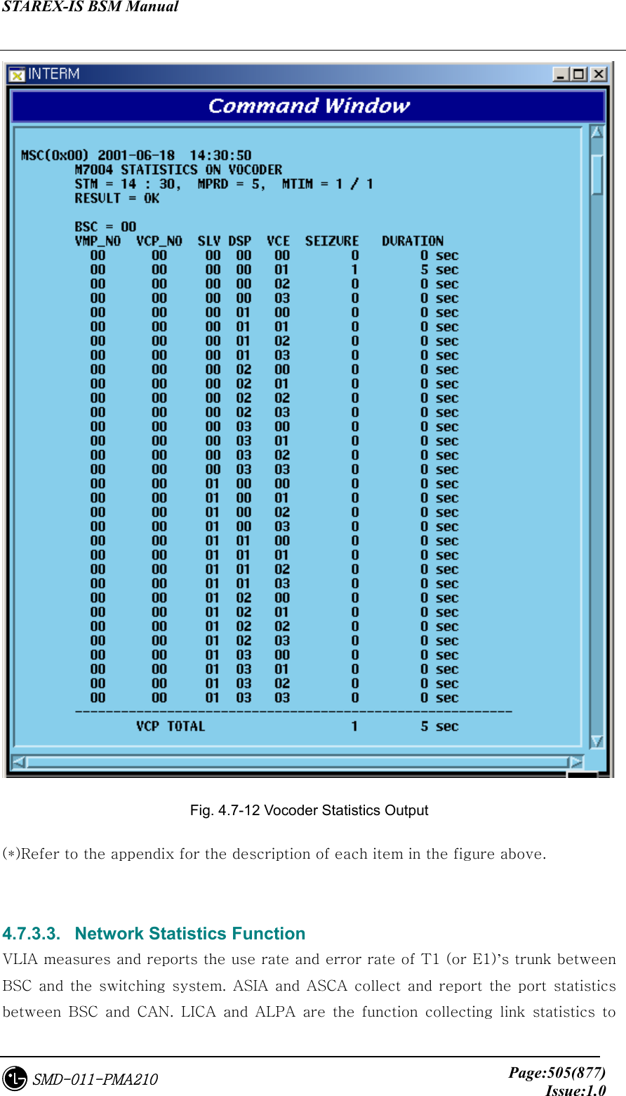
![STAREX-IS BSM Manual Page:504(877)Issue:1.0SMD-011-PMA210 Fig. 4.7-11 Channel Statistics Function (*)Refer to the appendix for the description of each items in the figure above. 4.7.3.2. Vocoder Statistics Function It is the function that measures and reports the occupancy count and time to vocoder which decodes/encodes voice corresponded to channel element by 1:1. The data is collected in VCP by VCE. Command : STAT-VOC:BSC=a,VMP=b[,VCP=c,MPRd=d,MTIM=e]; a : BSC : BSC number ( 0 ~ 11) b : BTS : BTS number ( 0 ~ 47) c : VMP : Vocoder Master Processor number(0 ~ 7) d : VCP : VCP number ( 0 ~ 15 ) e : MPRD : Cycle(min) : Default 30min f : MTIM : Repeat Count : Default 4times Display](https://usermanual.wiki/LG-Electronics-USA/3G1XOUTBTS.Users-Manual-Part-3/User-Guide-178515-Page-26.png)
![STAREX-IS BSM Manual Page:506(877)Issue:1.0SMD-011-PMA210 report between BSC and BTS. Command : STAT-NET:CAN=a,BSC=b[,BTS=c,ITEM=d,MPRD=e,MTIM=f]; a : CAN : the participation matter of the CAN equipment processor b : BSC : BSC number ( 0 ~ 11 ) c : BTS : BTS number ( 0 ~ 47) d : ITEM : Trunk(BSC↔Switching system) / Link(BSC↔BTS) / Port(BSC↔CAN) e : MPRD : Cycle(min) : Default 30min d : MTIM : Repeat Count : Default 4times Display Results Fig. 4.7-13 Network Statistics Output Results (*)Refer to the appendix for the description of each item in the figure above.](https://usermanual.wiki/LG-Electronics-USA/3G1XOUTBTS.Users-Manual-Part-3/User-Guide-178515-Page-28.png)
![STAREX-IS BSM Manual Page:507(877)Issue:1.0SMD-011-PMA210 4.7.3.4. Radio Channel Quality Statistics Function This function measures (Channel Element) and reports error rate and other things on radio channel between mobile subscriber and BTS. Command : STAT-CH:BSC=a[,BTS=b,MPRD=c,MTIM=d]; a : BSC : BSC number ( 0 ~ 11 ) b : BTS : BTS number ( 0 ~ 47 ) c : MPRD : Cycle(min) : Default 30min d : Measuring Count : Default 4times Display Results Fig. 4.7-14 Radio Channel Statistics Output Results (*)Refer to the appendix for the description of each item in the figure above. 4.7.3.5. Processor Statistics Function This is the function that each processor measures CPU and IPC load of each main processor at a given time to report to the BSM. Command : STAT-PRC:CAN=a,BSC=b[,BTS=c,MPRD=d,MTIM=e]; a : CAN : CAN equipment processor inclusion matter b : BSC : BSC number ( 0 ~ 11 ) c : BTS : BTS number ( 0 ~ 47 ) d : MPRD : Cycle(min) : Default 30min](https://usermanual.wiki/LG-Electronics-USA/3G1XOUTBTS.Users-Manual-Part-3/User-Guide-178515-Page-29.png)
![STAREX-IS BSM Manual Page:508(877)Issue:1.0SMD-011-PMA210 e : MTIM : Repeat Count : Default 4times Display Results Fig. 4.7-15 Processor Statistics Display Results (*)Refer to the appendix for the description of each item in the figure above. 4.7.3.6. Selector Statistics Function It is the statistics function that measures the occupying call, time, speed and bad frame counts of the selector. Commands : STAT-SLT:BSC=a,SMP=b[,SLP=c,MPRD=d,MTIM=e]; a : BSC : BSC number ( 0 ~ 11) b : SMP : Selector Master Processor number ( 0 ~ 4) c : SLP : Selector Processor number ( 0 ~ 19) d : MPRD : Cycle(min) : Default 30min e : MTIM : Count : Default 4times Display Results](https://usermanual.wiki/LG-Electronics-USA/3G1XOUTBTS.Users-Manual-Part-3/User-Guide-178515-Page-30.png)
![STAREX-IS BSM Manual Page:509(877)Issue:1.0SMD-011-PMA210 Fig. 4.7-16 Selector Statistics Display Results (*)Refer to the appendix for the description of each item in the figure above. 4.7.3.7. Performance (Call Delay) Statistics Function This is the function of BSP that measures and reports the setup delay (Time to Traffic, Channel Assign) of originating/terminating signal to mobile subscribers. Command : STAT-PERF:ITEM=a, BSC=b[,BTS=c,MPRD=d,MTIM=e]; a : ITEM : ALL-Measure originating and terminating, ORG – Originating, TRM- Terminating b : BSC : BSC number ( 0 ~ 11 ) c : BTS : BTS number ( 0 ~ 47 ) d : MPRD : Cycle(min) : Default 30min e : MTIM : Repeat Count : Default 4times Display Results](https://usermanual.wiki/LG-Electronics-USA/3G1XOUTBTS.Users-Manual-Part-3/User-Guide-178515-Page-31.png)
![STAREX-IS BSM Manual Page:510(877)Issue:1.0SMD-011-PMA210 Fig. 4.7-17 Call Delay Performance Statistics Display Results (*)Refer to the appendix for the description of each item in the figure above. 4.7.3.8. Paging Statistics Function This is the function of BSP to measure and report the attempt, success and failure counts of paging to the mobile subscriber. Command : STAT-PAGE:BSC=a[,BTS=b, MPRD=c, MTIM=d]; a: BSC : BSC number( 0 ~ 11 ) b: BTS : BTS number( 0 ~ 47 ) c: MPRD : Cycle(min) : Default 30min d: MTIM : Repeat Count : Default 4times Display Results](https://usermanual.wiki/LG-Electronics-USA/3G1XOUTBTS.Users-Manual-Part-3/User-Guide-178515-Page-32.png)
![STAREX-IS BSM Manual Page:511(877)Issue:1.0SMD-011-PMA210 Fig. 4.7-18 Paging Statistics Display Results (*)Refer to the appendix for the description of each item in the figure above. 4.7.3.9. CAI Statistics Function This is the function of BSP to measure and report the CAI signaling message at a given time which is transmitted and received by access channel and paging channel. Command : STAT-CAI:ITEM=a,BSC=b[,BTS=c,MPRD=d,MTIM=e]; a : ITEM : ALL – Access, Paging channel both to be measured PC – Paging channel only to be measured AC – Access channel only to be measured b : BSC : BSC number ( 0 ~ 11 ) c : BTS : BTS number ( 0 ~ 47 ) d : MPRD : Cycle(min) : Default 30min e : MTIM : Repeat Count : Default 4times Display Count](https://usermanual.wiki/LG-Electronics-USA/3G1XOUTBTS.Users-Manual-Part-3/User-Guide-178515-Page-33.png)
![STAREX-IS BSM Manual Page:512(877)Issue:1.0SMD-011-PMA210 Fig. 4.7-19 CAI Statistics Display Results (*)Refer to the appendix for the description of each item in the figure above. 4.7.3.10. No.7 Signaling Statistics No.7 signaling is the function of SCP to collect by sorting into MTP and SCCP, and report it to the BSM. Command : STAT-NO7:ITEM=a,SCP=b[,MPRD=c,MTIM=d]; a : ITEM : MTP, SCCP or ALL b : SCP : SCP(BSC) Number(0~11) c : MPRD : execution cycle(5~60min, default:30min) d : MTIM : execution count(1~100, default:4) Display Results](https://usermanual.wiki/LG-Electronics-USA/3G1XOUTBTS.Users-Manual-Part-3/User-Guide-178515-Page-34.png)
![STAREX-IS BSM Manual Page:513(877)Issue:1.0SMD-011-PMA210 Fig. 4.7-20 No.7 Signaling Statistics Display Results (*)Refer to the appendix for the description of each item in the figure above. 4.7.3.11. RTD Statistics Round Trip Delay Statistics: BSP collects and reports the converted time from BTS antenna to BTS antenna via MS into distance. Command : STAT-RTD:BSC=a,BTS=b[,MPRD=c,MTIM=d]; a : BSC : BSC number ( 0 ~ 11 ) b : BTS : BTS number ( 0 ~ 47 ) c : MPRD : Cycle(min) : Default 30min d : MTIM : Repeat Count : Default 4times Display Results](https://usermanual.wiki/LG-Electronics-USA/3G1XOUTBTS.Users-Manual-Part-3/User-Guide-178515-Page-35.png)
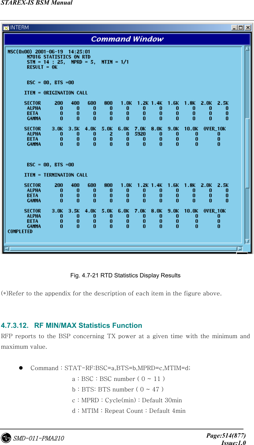
![STAREX-IS BSM Manual Page:515(877)Issue:1.0SMD-011-PMA210 Display Results Fig. 4.7-22 RF Min/Max Statistics Function Display Results (*)Refer to the appendix for the description of each item in the figure above. 4.7.4. Packet Related Packet related statistics function is as followed. Fig. 4.7-23 Packet Statistics Function 4.7.4.1. Packet Data Statistics Function PIP collects average data transmission between BSC and PDSN and reports it to the BSM through PCP. Command : STAT-PKD:PCP=a,SHELF=b[,PIP=c, MPRD=d, MITM=e];](https://usermanual.wiki/LG-Electronics-USA/3G1XOUTBTS.Users-Manual-Part-3/User-Guide-178515-Page-37.png)
![STAREX-IS BSM Manual Page:516(877)Issue:1.0SMD-011-PMA210 a : PCP : PCP number ( 0 ~ 2 ) b : SHELF : Shelf number ( SHELF 0, SHELEF 1, ALL) c : PIP : PIP number ( 0 ~ 11 ) d : MPRD : cycle(min) : Default 30min e : MTIME : Repeat Count : count 4times Display Results Fig. 4.7-24 Packet Data Statistics Display Results (*)Refer to the appendix for the description of each item in the figure above. 4.7.4.2. Packet Control Statistics Function It is the function to collect and report to BSM regarding the following: the call attempt count and call success count, the attempt count and success count of packet call transition from dormant status to active status, and each average call holding time between BSC and PDSN. Command : STAT-PKC:PCP=a[,MPRD=b,MTIM=c]; a : PCP : PCP number ( 0 ~ 2 ) b : MPRD : cycle(min) : Default 30min c : MTIM : Repeat Count : Default 4min](https://usermanual.wiki/LG-Electronics-USA/3G1XOUTBTS.Users-Manual-Part-3/User-Guide-178515-Page-38.png)
![STAREX-IS BSM Manual Page:517(877)Issue:1.0SMD-011-PMA210 Display Results Fig. 4.7-25 Packet Control Statistics Function Results Display (*)Refer to the appendix for the description of each item in the figure above. 4.7.4.3. Packet Handoff Statistics Function PCP collects and reports the following statistics data to BSM: attempt and failure count of inter BSC hard handoff occurred in the packet traffic procedure by dormant or active status. Command : STAT-PKH:PCP=a[,MPRD=b,MTIM=c]; a : PCP : PCP number ( 0 ~ 2 ) b : MPRD : Cycle(min) : Default 30min](https://usermanual.wiki/LG-Electronics-USA/3G1XOUTBTS.Users-Manual-Part-3/User-Guide-178515-Page-39.png)
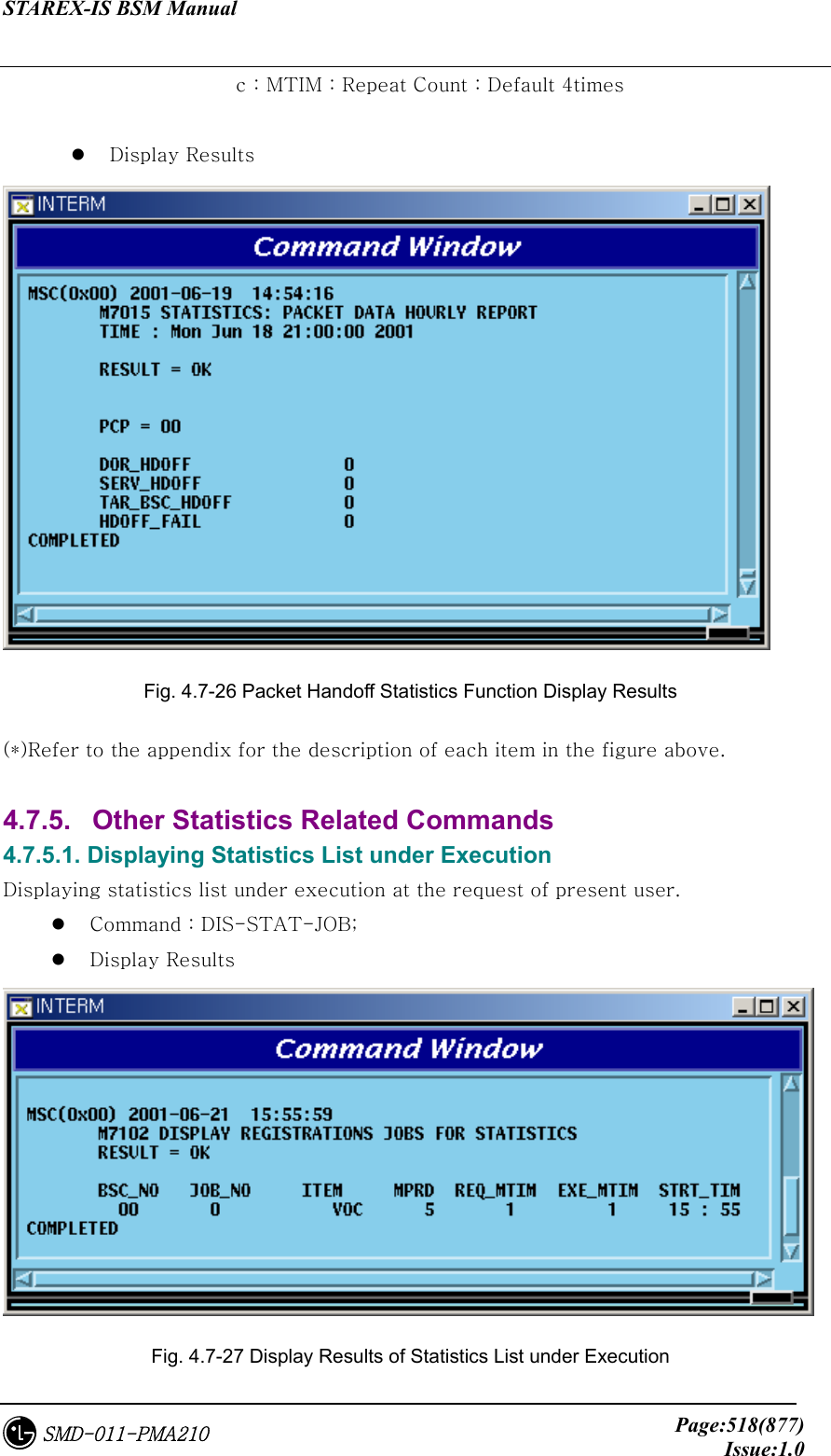
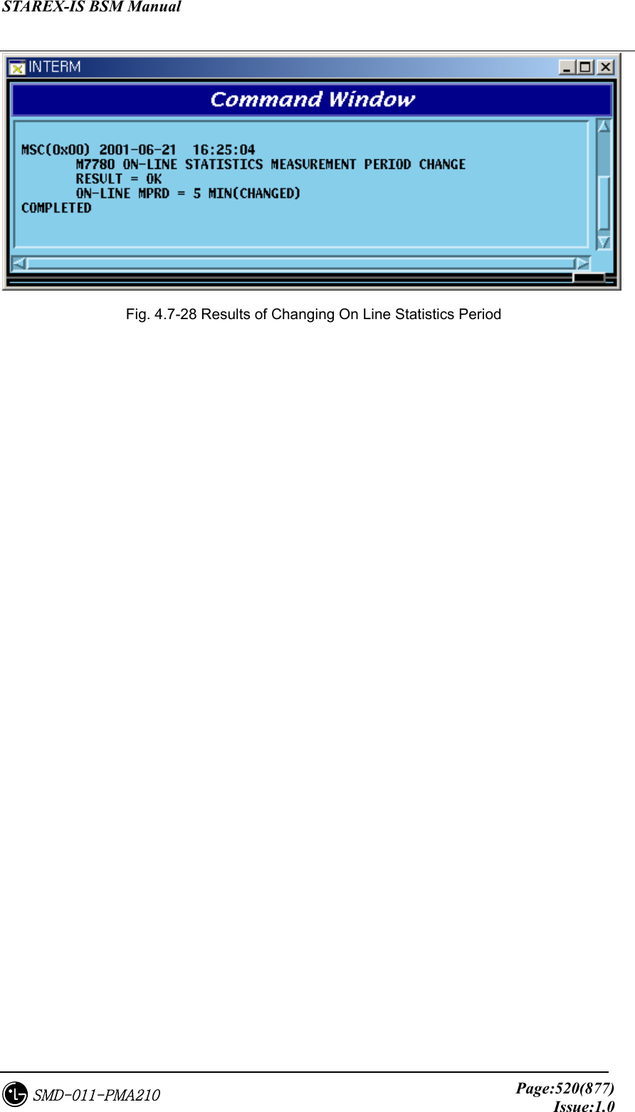
![STAREX-IS BSM Manual Page:519(877)Issue:1.0SMD-011-PMA210 4.7.5.2. Statistics Cancel Command This is the function to cancel On Demand statistics command under execution. Command : CANC-STAT:[BSC=a,]JOB=b; a : BSC : BSC number( 0 ~ 11 ) b : JOB : Statistics number ( 0 ~ 7) 4.7.5.3. Hourly / Daily Statistics Data Display Command This is the function that displays the hourly statistics data collected and stored by BSM through the BSM Interm window. Hourly Statistics Display Command: DIS-HLY-DATA:HOUR=a,ITEM=b,BSC=c,BTS=d; a : HOUR : Time (00 ~ 23) b : ITEM : Kinds of Statistics c : BSC : BSC number ( 0 ~ 11 ) d : BTS : BTS number ( 0 ~ 47 ) Daily Statistics Display: DIS-HLY-DATA:WEEK=a,HOUR=b,ITEM=c,BSC=d,BTS=e; a : WEEK : Day of the Week ( MON/TUE/WED/THU/FRI/SAT/SUN) b : HOUR : hour (00 ~ 23) c : ITEM : Kinds of Statistics d : BSC : BSC number ( 0 ~ 11 ) e : BTS : BTS number ( 0 ~ 47 ) 4.7.5.4. On Line Statistics Period Change This is the function to change the period (basically 5minute) of online statistics(real-time traffic statistics) collected by CCP. Command : CHG-ONLINE-MPRD:MPRD=a; a : MPRD : Period(min) to be changed Execution Results](https://usermanual.wiki/LG-Electronics-USA/3G1XOUTBTS.Users-Manual-Part-3/User-Guide-178515-Page-41.png)
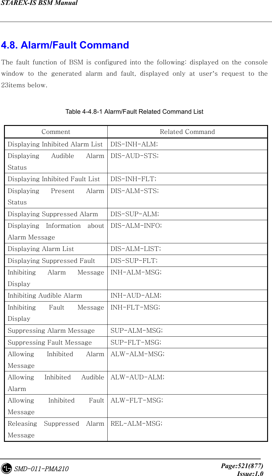
![STAREX-IS BSM Manual Page:523(877)Issue:1.0SMD-011-PMA210 4.8.1. Alarm/Fault Display 4.8.1.1. Display Command of Inhibited Alarm Message List This is the command to display the list of the alarm message whose display is inhibited. Check the Inhibit status when the alarm to be generated is not generated; if it is not inhibited, check the Suppress status. Table 4-4.8-2 The meaning of Input by BSC Number and BTS Number BSC BTS Meaning Input Input BTS Input X BSC X X CAN X Input Input Error *Note) The applying scope of the table above equally applied to the Alarm/Fault related command. • Command DIS-INH-ALM:[BSC=a],[BTS=b]; a : BSC Number(0 ~ 11) b : BTS Number(0 ~ 47) • Input DIS-INH-ALM:BSC=0; • Display Fig. 4.8-1 Display Result of the Display Inhibited Alarm Message List 4.8.1.2. Display Command for the Audible Alarm Status This command displays the alarm panel status, presently generated alarm status and inhibition status of the audible alarm.](https://usermanual.wiki/LG-Electronics-USA/3G1XOUTBTS.Users-Manual-Part-3/User-Guide-178515-Page-45.png)
![STAREX-IS BSM Manual Page:524(877)Issue:1.0SMD-011-PMA210 • Command DIS_AUD-STS; • Display Fig. 4.8-2 Display Result of the Display Command for Audible Alarm Status 4.8.1.3. Display Command for Inhibited Fault Message List This is the command for the display inhibited fault messages to display their list. If fault message to be generated were not generated this command would be needed to check the Inhibit status. • Command DIS-INH-FLT:[BSC=a],[BTS=b]; a : BSC Number(0 ~ 11) b : BTS Number(0 ~ 47) • Input DIS-INH-FLT:BSC=0, BTS=1; • Display Fig. 4.8-3 Display Result of the List for the Display Inhibited Fault Message](https://usermanual.wiki/LG-Electronics-USA/3G1XOUTBTS.Users-Manual-Part-3/User-Guide-178515-Page-46.png)
![STAREX-IS BSM Manual Page:525(877)Issue:1.0SMD-011-PMA210 4.8.1.4. Display Command for the Present Alarm Status This is the display command for the information about the presently generated alarm. If the user would like to see the alarm code only, input nothing or OFF in the Detail Option. • Command DIS-ALM-STS[:BSC=a],[BTS=b],[DETAIL=c]; a : BSC Number(0 ~ 11) b : BTS Number(0 ~ 47) c : DETAIL Option(ON/OFF) ON : Alarm Code + Alarm Info. + Alarm Generated Location OFF: Alarm Code + Corresponding Alarm count(default) (1) In the case of DETAIL = ON • Input DIS-ALM-STS:BSC=0,BTS=0,DETAIL=ON; • Display Fig. 4.8-4 Display Result of Display Command for the Present Alarm Status (2) In the case of DETAIL = OFF • Input DIS-ALM-STS:BSC=0,BTS=0,DETAIL=OFF; • Display](https://usermanual.wiki/LG-Electronics-USA/3G1XOUTBTS.Users-Manual-Part-3/User-Guide-178515-Page-47.png)
![STAREX-IS BSM Manual Page:526(877)Issue:1.0SMD-011-PMA210 Fig. 4.8-5 Display Result of Display Command for Present Alarm Status 4.8.1.5. Display Command for Suppressed Alarm Message This is the command for suppress alarm message to be displayed. • Command DIS-SUP-ALM:[BSC=a],[BTS=b]; a : BSC Number(0 ~ 11) b : BTSNumber(0 ~ 47) • Input DIS-SUP-ALM:BSC=0,BTS=0; • Display Fig. 4.8-6 Display Result of Display Command for the Suppressed Alarm Message 4.8.1.6. Display Command for the Information about Alarm Message This is the command to display the defined grade of the alarm message and alarm message information. • Command DIS-ALM-INFO:AN=a; a : Alarm Code Number(100 ~ 9999) • Input DIS-ALM-INFO:AN=1000; or DIS-ALM-INFO:1000;](https://usermanual.wiki/LG-Electronics-USA/3G1XOUTBTS.Users-Manual-Part-3/User-Guide-178515-Page-48.png)
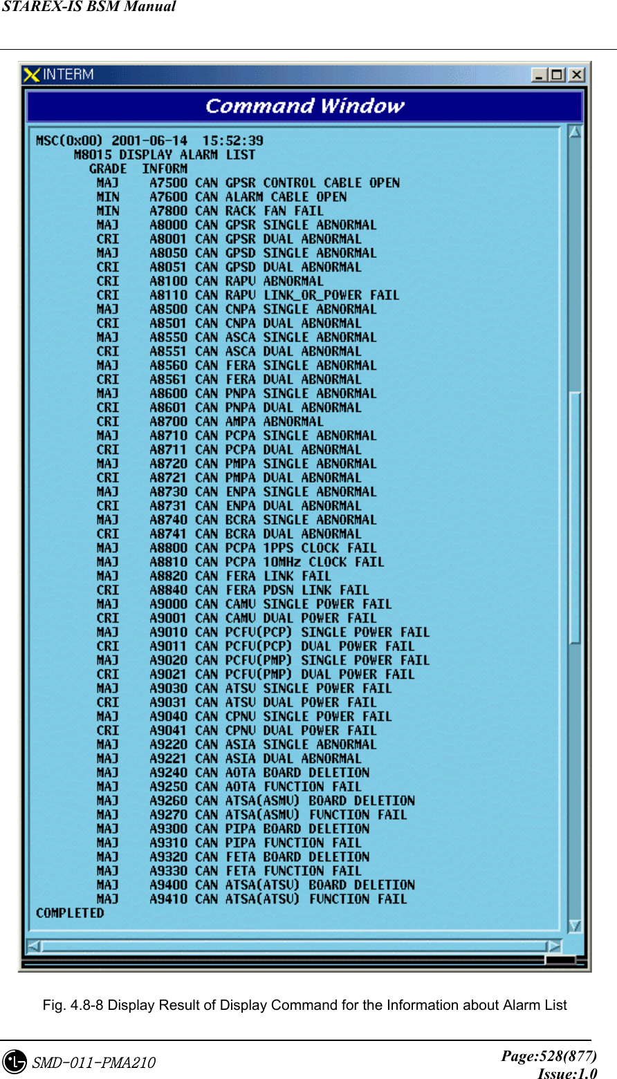
![STAREX-IS BSM Manual Page:527(877)Issue:1.0SMD-011-PMA210 • Display Fig. 4.8-7 Display Result of Display Command for Information about the Alarm Message 4.8.1.7. Display Command for Alarm List This is the command to display the list for all kinds of alarm. • Command DIS-ALM-LIST:[SUB-SYS=a]; a : Subsystem Name(CAN/BSC/BTS/ALL) • Input DIS-ALM-INFO:CAN; • Display](https://usermanual.wiki/LG-Electronics-USA/3G1XOUTBTS.Users-Manual-Part-3/User-Guide-178515-Page-49.png)
![STAREX-IS BSM Manual Page:529(877)Issue:1.0SMD-011-PMA210 4.8.1.8. Display Command for the List of the Suppressed Fault Message This is the command to display the Fault Source Code List for the suppressed fault message. • Command DIS-SUP-FLT:[BSC=a],[BTS=b]; a : BSC Number(0 ~ 11) b : BTS Number(0 ~ 47) • Input DIS-SUP-FLT:BSC=0,BTS=0; • Display Fig. 4.8-9 Display Result of Display Command for the Suppress Fault Message List 4.8.2. Alarm/Fault Inhibition 4.8.2.1. Inhibition Command for Alarm Message This is the function to inhibit the alarm message to be displayed on the console window. If any Alarm Code is not designated it inhibits the entire alarm message generated in the designated system. • Command INH-ALM-MSG:[BSC=a],[BTS=b],[AN=c]; a : BSC Number(0 ~ 11) b : BTS_GRP Number(0 ~ 47) c : Alarm Code Number(0 ~ 9999) • Input INH-ALM-MSG:BSC=0,AN=4600; • Display](https://usermanual.wiki/LG-Electronics-USA/3G1XOUTBTS.Users-Manual-Part-3/User-Guide-178515-Page-51.png)
![STAREX-IS BSM Manual Page:530(877)Issue:1.0SMD-011-PMA210 Fig. 4.8-10 Display Result of Display Inhibition for Alarm Message *Note) AN : Alarm Number 4.8.2.2. Inhibition Command for Audible Alarm The audible alarm can be inhibited by the grade and it is applied to all kinds of alarm. • Command INH-AUD-ALM • Display Fig. 4.8-11 Display Result of Inhibition Command for Audible Alarm 4.8.2.3. Inhibition Command for Fault Message This is the function to inhibit the display of the fault message. If any fault code is not designated, it inhibits all the fault codes. • Command INH-FLT-MSG:[BSC=a],[BTS=b],[FN=c]; a : BSC Number(0 ~ 11) b : BTS Number(0 ~ 47)](https://usermanual.wiki/LG-Electronics-USA/3G1XOUTBTS.Users-Manual-Part-3/User-Guide-178515-Page-52.png)
![STAREX-IS BSM Manual Page:531(877)Issue:1.0SMD-011-PMA210 c : Fault Code Number • Input INH-FLT-MSG:BSC=0,BTS=0,FN=1000; • Display Fig. 4.8-12 Display Result of Inhibition/Allowance for Fault Message Display 4.8.2.4. Alarm Message Suppress Command This command is used for the following cases: when previously checked alarm(by the user) is generating and burden BSM; when suppressing the report for the alarm message from subsystem in order to monitor other important message. This is the command blocking the message itself for the unnecessary alarm contrary to the command (INH-ALM-MSG) which inhibits the alarm message to be displayed on the BSM console window. • Command SUP-ALM-MSG:[BSC=a],[BTS=b],[SRC_CODE=c]; a : BSC Number(0 ~ 11) b : BTS Number(0 ~ 47) c : Alarm Source Code Number(1 ~ 9999) • Input SUP-ALM-MSG:BSC=0,BTS=0,SRC_CODE=30001; • Display](https://usermanual.wiki/LG-Electronics-USA/3G1XOUTBTS.Users-Manual-Part-3/User-Guide-178515-Page-53.png)
![STAREX-IS BSM Manual Page:532(877)Issue:1.0SMD-011-PMA210 Fig. 4.8-13 Display Result of the Suppress Alarm Message Command 4.8.2.5. Fault Message Suppress Command This command is used for the following cases: when previously checked fault message(by the user) is generating and burden BSM; when suppressing the report for the fault message from subsystem in order to monitor other important message. This is the command blocking the message itself for the unnecessary fault message contrary to the command (INH-FLT-MSG) which inhibits the fault message to be displayed on the BSM console window. • Command SUP-FLT-MSG:[BSC=a],[BTS=b],[SRC_CODE=c]; a : BSC Number(0 ~ 11) b : BTS Number(0 ~ 47) c : Fault Source Code Number(1 ~ 1000) • Input SUP-FLT-MSG:BSC=0,BTS=0,SRC_CODE=31001; • Display Fig. 4.8-14 Display Result for the Fault Message Suppress Command](https://usermanual.wiki/LG-Electronics-USA/3G1XOUTBTS.Users-Manual-Part-3/User-Guide-178515-Page-54.png)
![STAREX-IS BSM Manual Page:533(877)Issue:1.0SMD-011-PMA210 4.8.3. Alarm/Fault Control 4.8.3.1. Allowance Command for Inhibited Alarm Message Display This is the command to allow randomly inhibited alarm message for display by the user. If any specific alarm code is not designated, all the inhibited alarm code for display in the designated system is allowed. • Command ALW-ALM-MSG:[BSC=a],[BTS=b],[AN=c]; a : BSC Number(0 ~ 11) b : BTS Number(0 ~ 47) c : Alarm Code Number(0 ~ 9999) • Input ALW-ALM-MSG:BSC=0,AN=4600; • Display Fig. 4.8-15 Display Result of Allowance for Alarm Message Display Inhibition 4.8.3.2. Allowance Command for Inhibited Audible Alarm This is the command to allow inhibited audible alarm. • Command ALW-AUD-ALM • Display](https://usermanual.wiki/LG-Electronics-USA/3G1XOUTBTS.Users-Manual-Part-3/User-Guide-178515-Page-55.png)
![STAREX-IS BSM Manual Page:534(877)Issue:1.0SMD-011-PMA210 Fig. 4.8-16 Display Result of Allowance Command for Inhibited Audible Alarm 4.8.3.3. Allowance Command for Inhibited Fault Message Display This is the command to allow randomly inhibited fault message by the user. If any specific alarm code is not designated, all the inhibited fault code for display is allowed. • Command ALW-FLT-MSG:[BSC=a],[BTS=b],[FN=c]; a : BSC Number(0 ~ 11) b : BTS Number(0 ~ 47) c : Fault Code Number(1000 ~ 9999) • Input ALW-FLT-MSG:BSC=0,BTS=1,FN=1000; • Display Fig. 4.8-17 Display Result for Allowing Fault Message Display Inhibition 4.8.3.4. Release Command for Suppressed Alarm Message This is the command to release randomly suppressed alarm message by the user. If there were any follow-up measures after suppressing and the suppressing is not](https://usermanual.wiki/LG-Electronics-USA/3G1XOUTBTS.Users-Manual-Part-3/User-Guide-178515-Page-56.png)
![STAREX-IS BSM Manual Page:535(877)Issue:1.0SMD-011-PMA210 needed any more, it is highly recommended to release the suppress by this command. If the alarm is not generated in the required situation the suppress matter should be checked. • Command REL-ALM-MSG:[BSC=a],[BTS=b],[SRC_CODE=c]; a : BSC Number(0 ~ 11) b : BTS Number(0 ~ 47) c : Alarm Source Code Number(1 ~ 9999) • Input REL-ALM-MSG:BSC=0,BTS=0,SRC_CODE=30001; • Display Fig. 4.8-18 Display Result of Release Command for Suppressed Alarm Message 4.8.3.5. Release Command for Suppressed Fault Message This is the command to release randomly suppressed fault message by the user. If there were any follow-up measures to the suppressed message and the suppressing is not needed any more, it is recommended to release the suppress by this command. • Command REL-FLT-MSG:[BSC=a],[BTS=b],[SRC_CODE=c]; a : BSC Number(0 ~ 11) b : BTS Number(0 ~ 47) c : Fault Source Code Number(1 ~ 1000) • Input REL-FLT-MSG:BSC=0,BTS=0,SRC_CODE=31001; • Display](https://usermanual.wiki/LG-Electronics-USA/3G1XOUTBTS.Users-Manual-Part-3/User-Guide-178515-Page-57.png)
![STAREX-IS BSM Manual Page:536(877)Issue:1.0SMD-011-PMA210 Fig. 4.8-19 Display Result of Release Command for Suppressed Fault Message 4.8.4. Environment Alarm Control 4.8.4.1. Environment Alarm Flag set Command This is the command to decide (ON/OFF) whether to receive the alarm, which is sensed by the sensor of environment monitoring module, normally or not. ON means receiving the alarm normally and OFF means non-receiving the alarm. • Command SET-ENV-FLAG:[BSC=a],[BTS=b],[CMD=c],[FLAG=d]; a : BSC Number(0 ~ 11) b : BTS Number(0 ~ 47) c : Command d : Flag(ON/OFF) • Input SET-ENV-FLAG: • Display a : RECTIFIER_SHUT_DOWN_ALARM FIRE UPPER_FLOOD LOWER_FLOOD TEMPERATURE1 TEMPERATURE2 MSC(0x00) date time M8030 SET ACU FLAG : a LOCATE = b RESEON = c](https://usermanual.wiki/LG-Electronics-USA/3G1XOUTBTS.Users-Manual-Part-3/User-Guide-178515-Page-58.png)
![STAREX-IS BSM Manual Page:537(877)Issue:1.0SMD-011-PMA210 TEMPERATURE3 TEMPERATURE_CENTIGRADE_OPTION HUMIDITY b : Locate Information c : #PROC_NOT_EQUIP ##PROC_ABNORMAL ##THIS COMMAND IS IN SERVICE ##NOK - BTS TYPE MISMATCH ##NOK - BAMA ABNORMAL ##NOK - ACU ABNORMAL ##NOK - RECTIFIER ABNORMAL ##NOK - BAMA NO RESPONSE ##NOK - ACU or REC NO RESPONSE ##NOK - ALREADY SET FLAG ON ##NOK - ALREADY SET FLAG OFF ##NOK - UNKNOWN REASON ##OK - SET FLAG COMPLETED 4.8.4.2. Environment Alarm Reset Command This is the reset command for environment monitoring module and the rectifier. • Command RST-ENV-STS:[BSC=a],[BTS=b],[CMD=c]; a : BSC Number(0 ~ 11) b : BTS Number(0 ~ 47) c : Command • Input RST-ENV-STS: • Display a : ACU_COLD_BOOT ACU_RESET RECTIFIER_POWER_TURN RECTIFIER_CONTOROLLER_RESET MSC(0x00) date time M8031 RESET ACU STATUS : a LOCATE = b RESEON = c](https://usermanual.wiki/LG-Electronics-USA/3G1XOUTBTS.Users-Manual-Part-3/User-Guide-178515-Page-59.png)
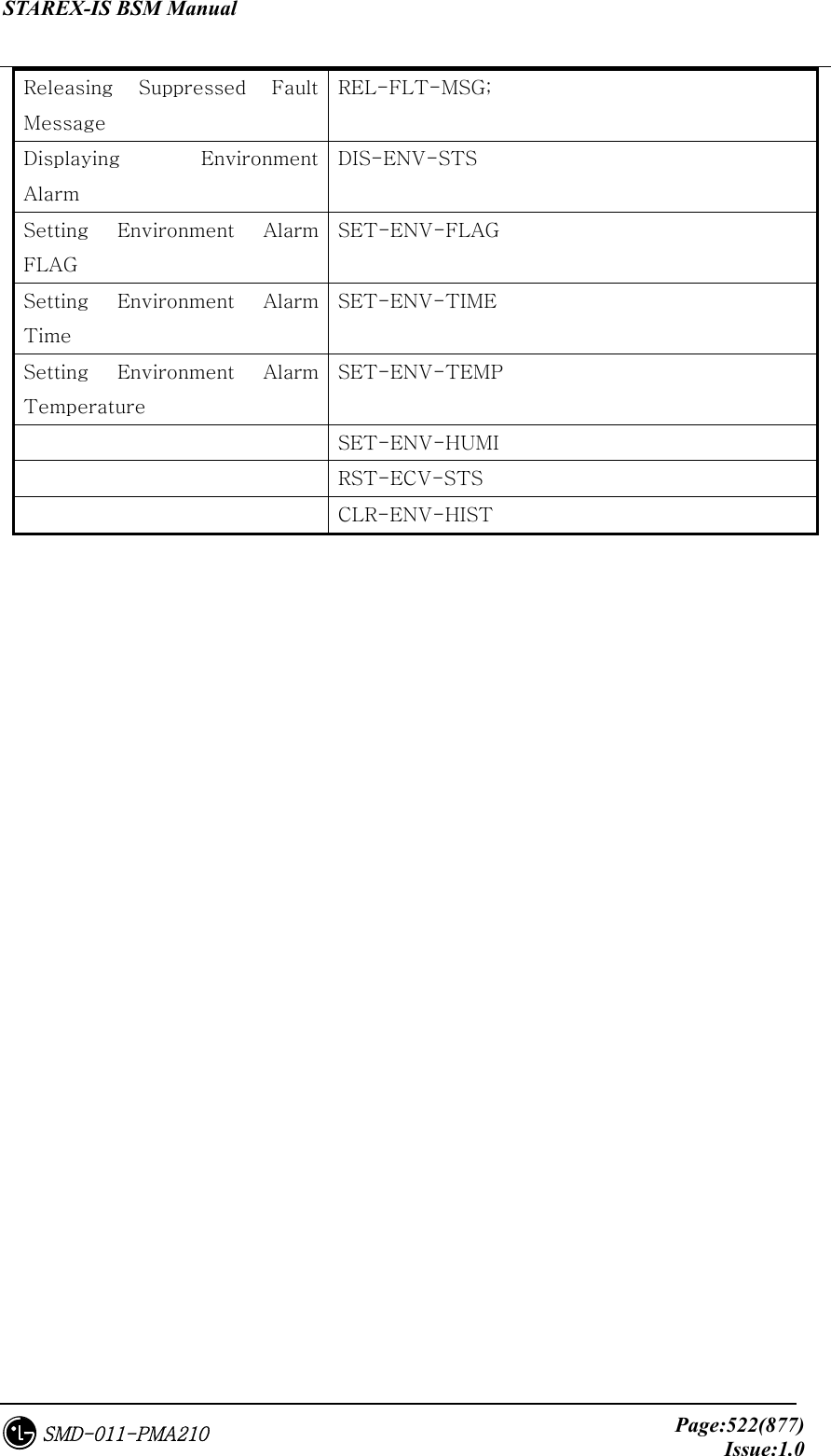
![STAREX-IS BSM Manual Page:538(877)Issue:1.0SMD-011-PMA210 b : Locate Information c : ##PROC_NOT_EQUIP ##PROC_ABNORMAL ##THIS COMMAND IS IN SERVICE ##NOK - BTS TYPE MISMATCH ##NOK - BAMA ABNORMAL ##NOK - ACU ABNORMAL ##NOK - RECTIFIER ABNORMAL ##NOK - BAMA NO RESPONSE ##NOK - ACU or REC NO RESPONSE ##NOK - UNKNOWN REASON ##OK - RESET COMPLETED 4.8.4.3. Environment Alarm History Clear Command This is the command to clear all the history stored in the environment monitoring module. • Command CLR-ENV-HIST:[BSC=a],[BTS=b],[CMD=c]; a : BSC Number(0 ~ 11) b : BTS Number(0 ~ 47) c : Command • Input CLR-ENV-HIST: • Display a : OP HISTORY RUNNING HISTORY b : Locate Information c : ##PROC_NOT_EQUIP ##PROC_ABNORMAL ##THIS COMMAND IS IN SERVICE ##NOK - BTS TYPE MISMATCH ##NOK - BAMA ABNORMAL MSC(0x00) date time M8032 HISTORY CLEAR : a LOCATE = b RESEON = c](https://usermanual.wiki/LG-Electronics-USA/3G1XOUTBTS.Users-Manual-Part-3/User-Guide-178515-Page-60.png)
![STAREX-IS BSM Manual Page:539(877)Issue:1.0SMD-011-PMA210 ##NOK - ACU ABNORMAL ##NOK - RECTIFIER ABNORMAL ##NOK - BAMA NO RESPONSE ##NOK - ACU or REC NO RESPONSE ##NOK - UNKNOWN REASON ##OK - CLEAR HISTORY COMPLETED 4.8.4.4. Time Set Command This is the command to set time (year/month/date/hour/minute/second) built in environment monitoring module. • Command SET-ENV-TIME:[BSC=a],[BTS=b],[YEAR=c],[MONTH=d],[DAY=e], [HOUR=f],[MINUTE=g],[SECOND=h]; a : BSC Number(0 ~ 11) b : BTS Number(0 ~ 47) c : Year(1990 ~ 2049) d : Month(1 ~ 12) e : Day(1 ~ 31) f : Hour(0 ~ 23) g : Minute(0 ~ 59) h : Second(0 ~ 59) • Input SET-ENV-TIME: • Display a : Locate Information b : #PROC_NOT_EQUIP ##PROC_ABNORMAL ##THIS COMMAND IS IN SERVICE ##NOK - BTS TYPE MISMATCH ##NOK - BAMA ABNORMAL ##NOK - ACU ABNORMAL ##NOK - RECTIFIER ABNORMAL MSC(0x00) date time M8033 SET ACU DATE AND TIME LOCATE = a RESEON = b](https://usermanual.wiki/LG-Electronics-USA/3G1XOUTBTS.Users-Manual-Part-3/User-Guide-178515-Page-61.png)
![STAREX-IS BSM Manual Page:540(877)Issue:1.0SMD-011-PMA210 ##NOK - BAMA NO RESPONSE ##NOK - ACU or REC NO RESPONSE ##NOK - UNKNOWN REASON ##OK - SET ACU TIME COMPLETED 4.8.4.5. Temperature Set Command This is the command to set the temperature (high/low/middle)’s threshold value of which the environment monitoring module takes control. If the temperature surpasses the set threshold value, the alarm is generating. • Command SET-ENV-TEMP: [BSC=a],[BTS=b],[HI_TEMP=c],[LOW_TEMP=d],[MID_TEMP=e]; a : BSC Number(0 ~ 11) b : BTS Number(0 ~ 47) c : High Temperature(0 ~ 200) d : Low Temperature(-20 ~ 200) e : Middle Temperature(-20 ~ 200) • Input SET-ENV-TEMP: • Display a : Locate Information b : ##PROC_NOT_EQUIP ##PROC_ABNORMAL ##THIS COMMAND IS IN SERVICE ##NOK - BTS TYPE MISMATCH ##NOK - BAMA ABNORMAL ##NOK - ACU ABNORMAL ##NOK - RECTIFIER ABNORMAL ##NOK - BAMA NO RESPONSE ##NOK - ACU or REC NO RESPONSE ##NOK - UNKNOWN REASON ##OK - SET ACU TEMPERATURE COMPLETED MSC(0x00) date time M8034 SET ACU ALARM VALUE TEMPERATURE(HIGH/LOW/MIDDLE) LOCATE = a RESEON = b](https://usermanual.wiki/LG-Electronics-USA/3G1XOUTBTS.Users-Manual-Part-3/User-Guide-178515-Page-62.png)
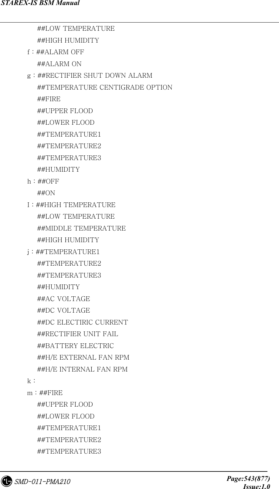
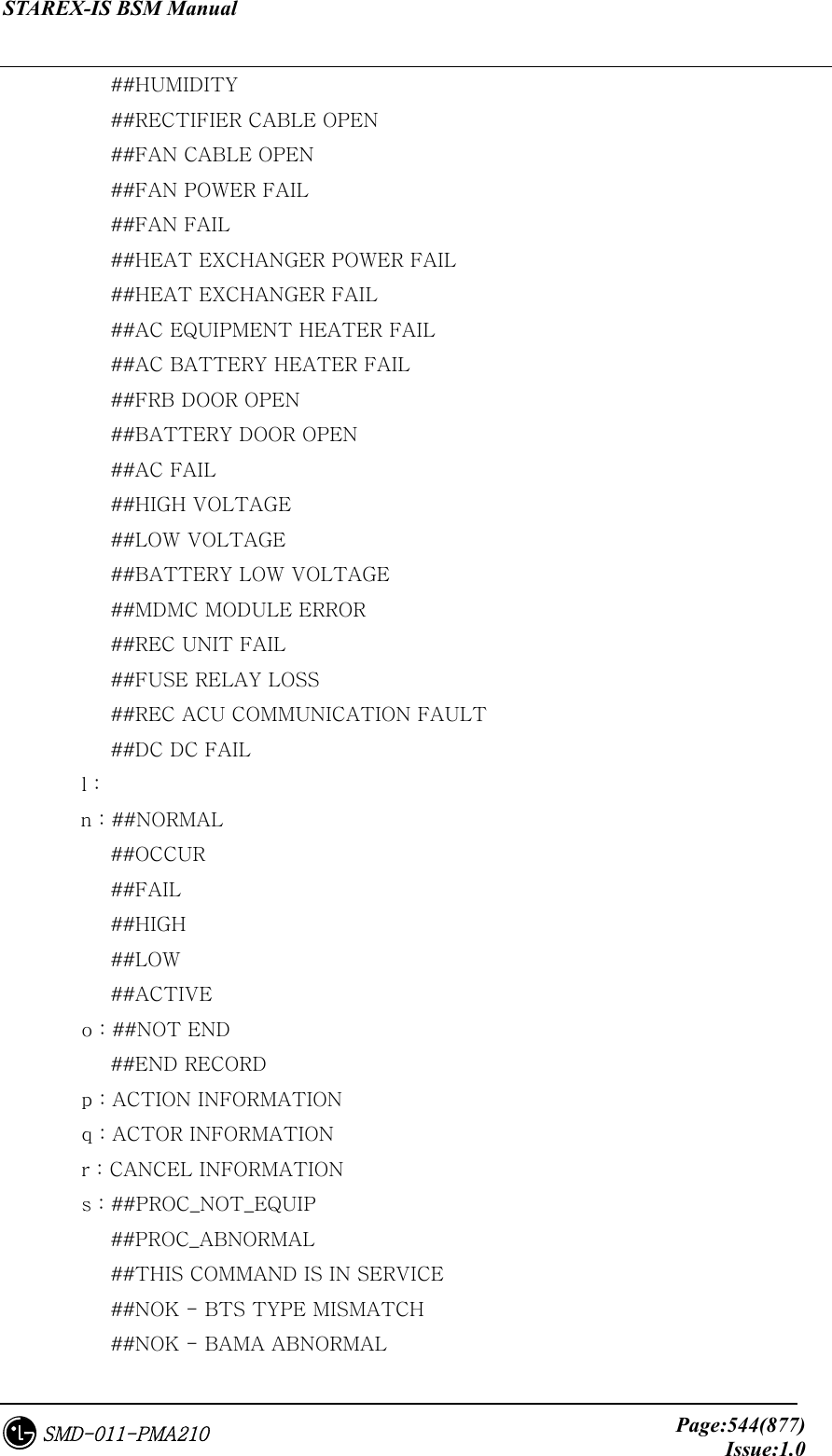
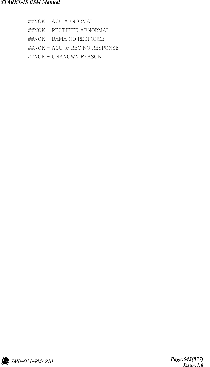
![STAREX-IS BSM Manual Page:541(877)Issue:1.0SMD-011-PMA210 4.8.4.6. Humidity Set Command This is the command to set the threshold value of humidity of which the environment monitoring module takes control. If humidity surpasses this threshold value, the alarm is generating. • Command SET-ENV-HUMI:[BSC=a],[BTS=b],[HI_HUMI=c]; a : BSC Number(0 ~ 11) b : BTS Number(0 ~ 47) c : High Humidity(0 ~ 100) • Input SET-ENV-HUMI: • Display a : Locate Information b : ##PROC_NOT_EQUIP ##PROC_ABNORMAL ##THIS COMMAND IS IN SERVICE ##NOK - BTS TYPE MISMATCH ##NOK - BAMA ABNORMAL ##NOK - ACU ABNORMAL ##NOK - RECTIFIER ABNORMAL ##NOK - BAMA NO RESPONSE ##NOK - ACU or REC NO RESPONSE ##NOK - UNKNOWN REASON ##OK - SET ACU HUMIDITY COMPLETED 4.8.4.7. Environment Alarm Display Command This is the command to display the parameter value, flag status, history and other things presently stored in the environment monitoring module. MSC(0x00) date time M8035 SET ACU HIGH HUMIDITY ALARM LIMITS VALUE LOCATE = a RESEON = b](https://usermanual.wiki/LG-Electronics-USA/3G1XOUTBTS.Users-Manual-Part-3/User-Guide-178515-Page-63.png)
![STAREX-IS BSM Manual Page:542(877)Issue:1.0SMD-011-PMA210 • Command DIS-ENV-STS:[BSC=a],[BTS=b],[CMD=c],[RECORD_NO=d]; a : BSC Number(0 ~ 11) b : BTS Number(0 ~ 47) c : Command d : Record Number(0 ~ 500) • Input DIS-ENV-STS: • Display A : Command B : Locate Information C : ACU TIME D : CURRENT TEMPERATURE AND HUMIDITY E : ##HIGH TEMPERATURE MSC(0x00) date time M8036 DISPLAY ACU STATUS : a LOCATE = b TIME : c CURRENT : d e - f g - h i - j - k - m l - n k - m l - n RECORD_NO : END_TRANSMIT : o ACTION = p ACTOR/STATE = q CANCELLATION = r REASON = s](https://usermanual.wiki/LG-Electronics-USA/3G1XOUTBTS.Users-Manual-Part-3/User-Guide-178515-Page-64.png)