LG Electronics USA 3G1XOUTBTS STAREX-IS 1900 Outdoor BTS User Manual STAREX IS User s Manual
LG Electronics USA STAREX-IS 1900 Outdoor BTS STAREX IS User s Manual
Contents
- 1. Users Manual Part 1
- 2. Users Manual Part 2
- 3. Users Manual Part 3
- 4. Users Manual Part 4
- 5. Users Manual Part 5
Users Manual Part 5


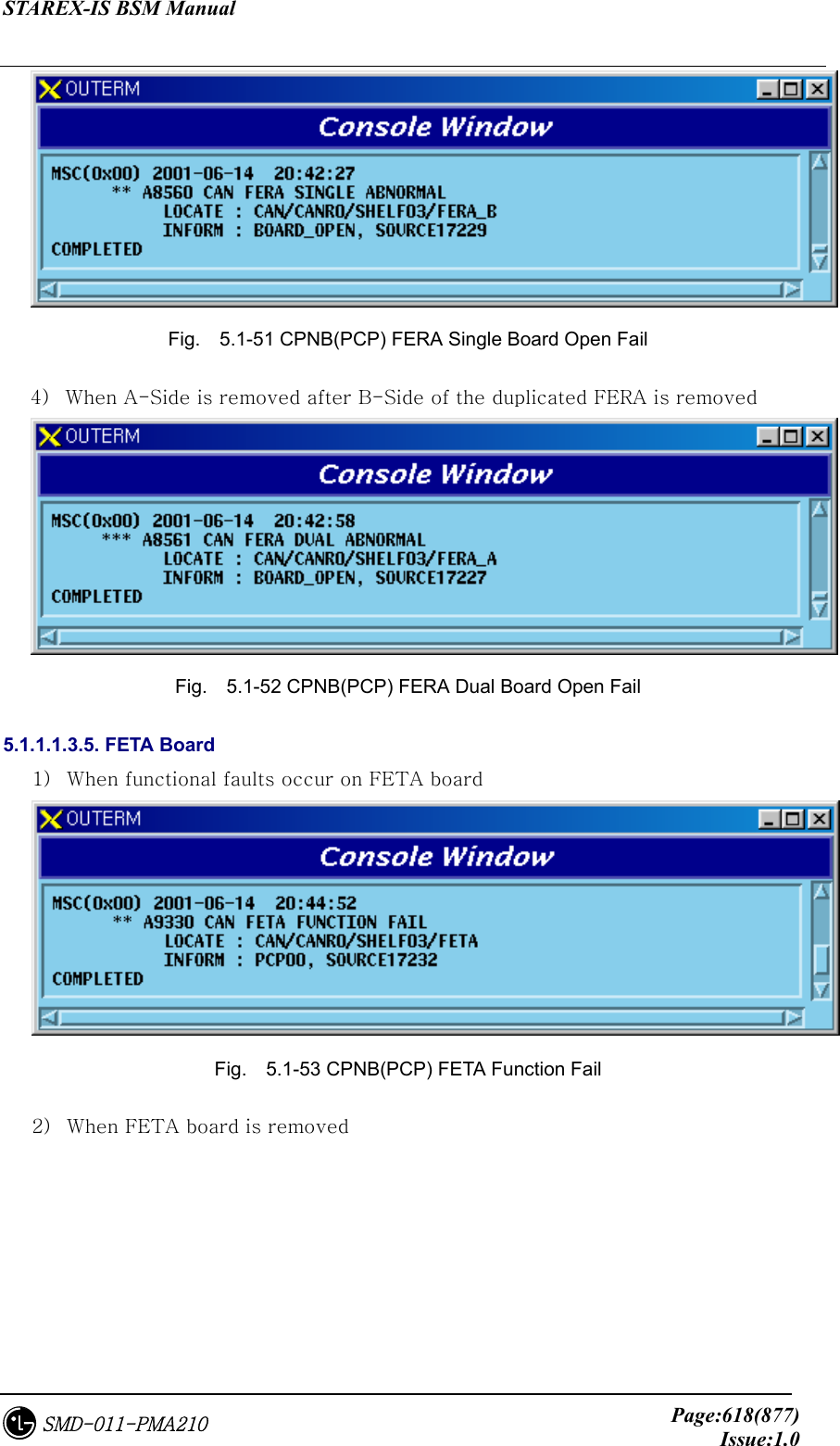


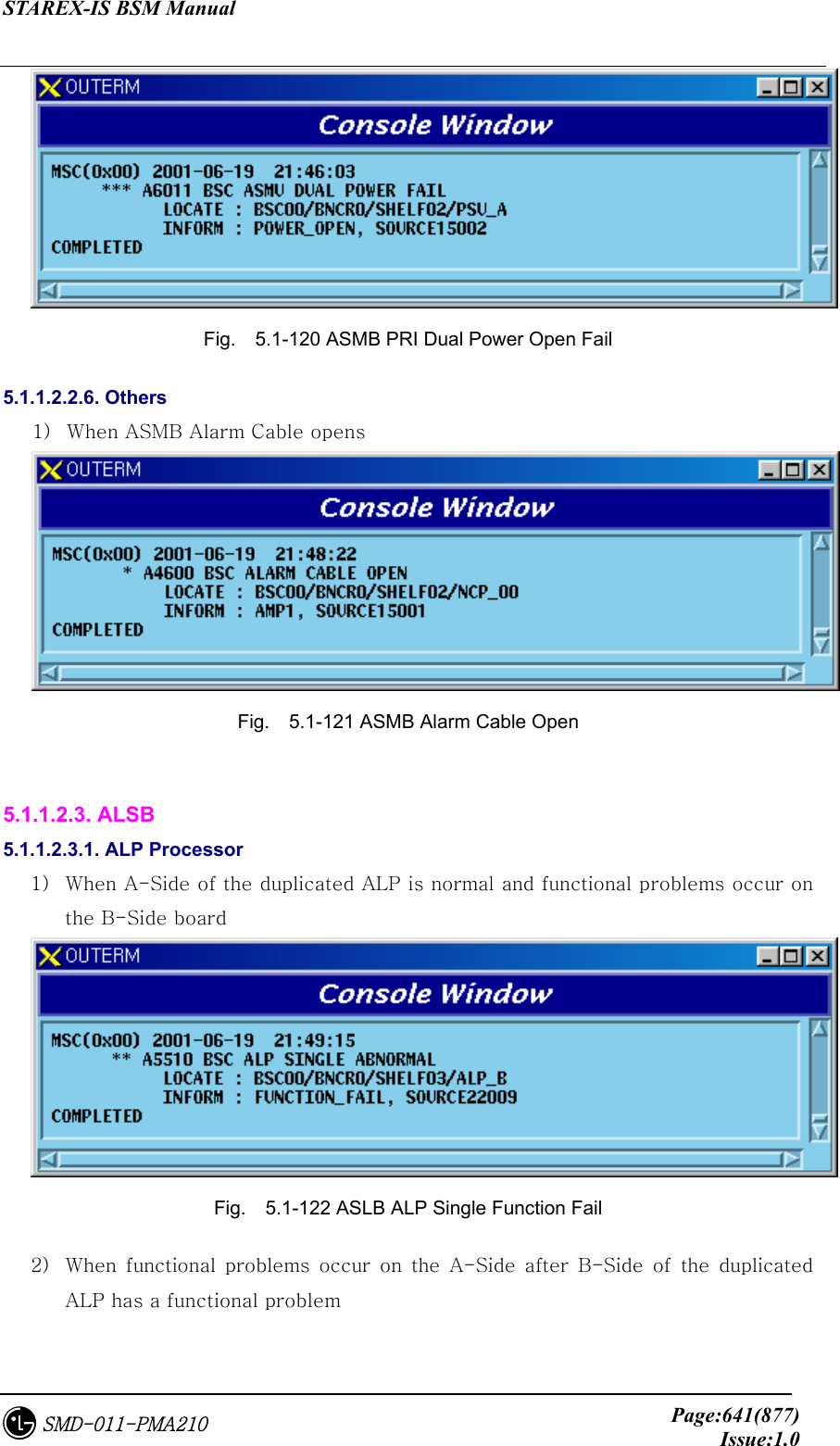


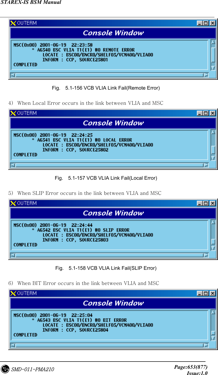


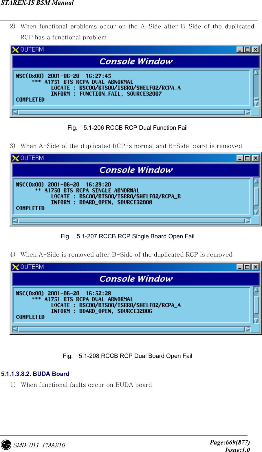


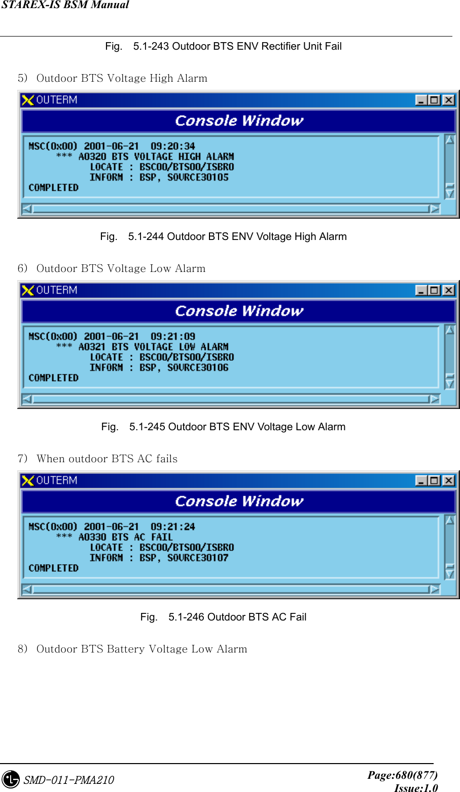


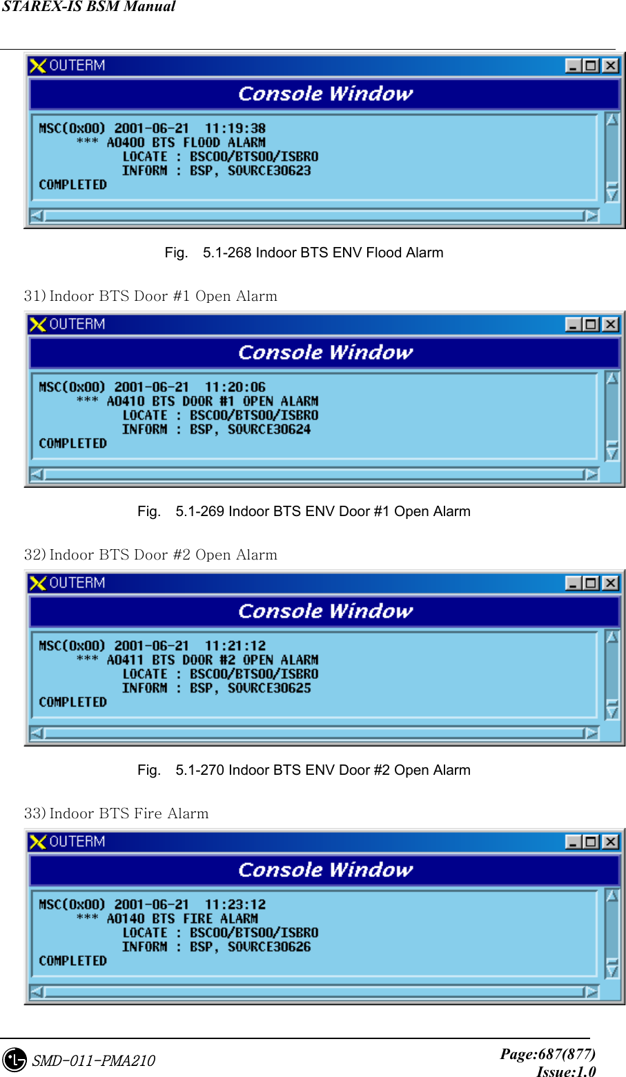

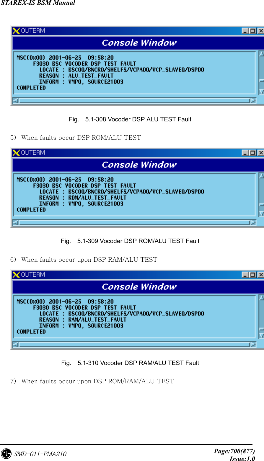
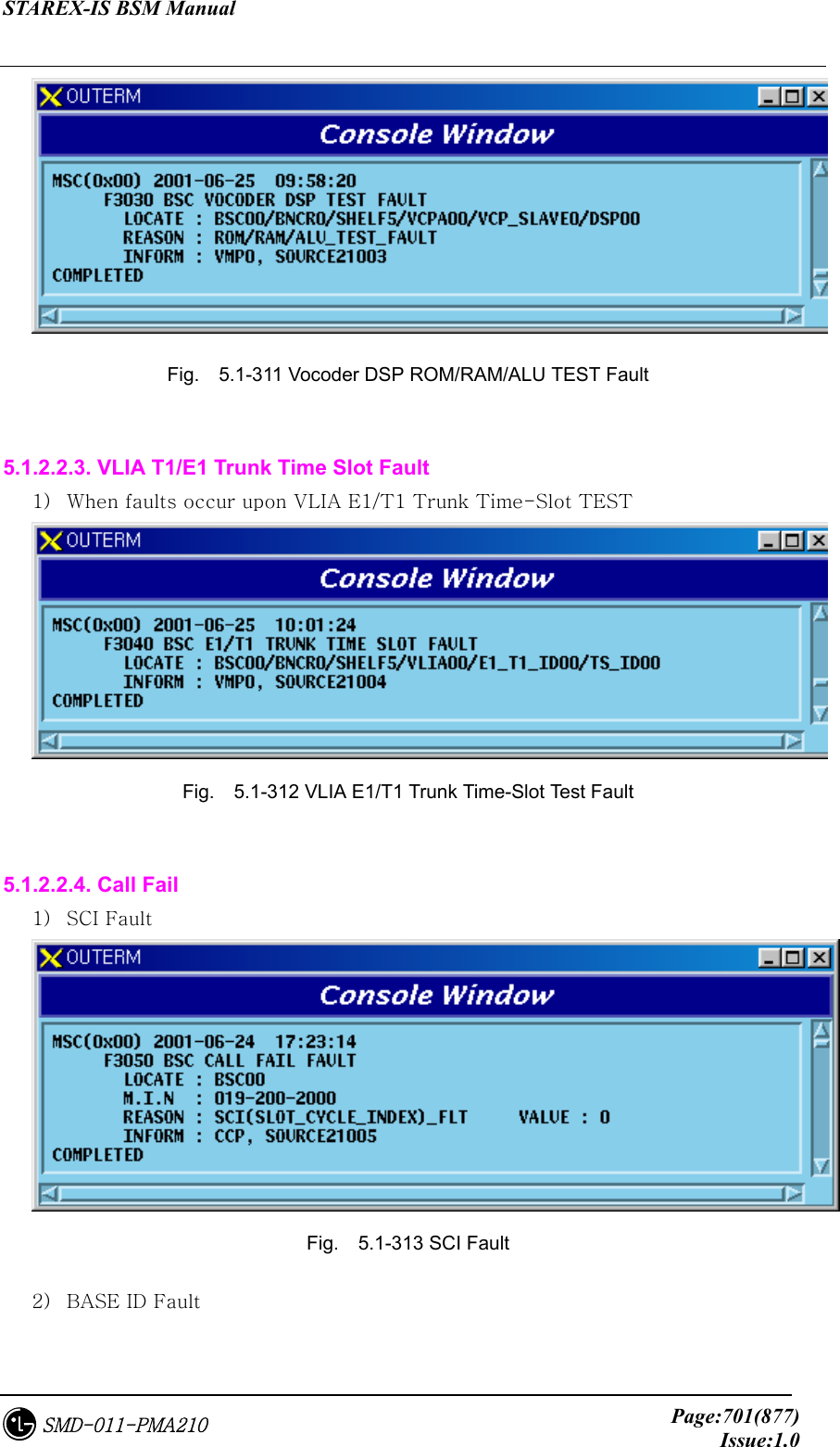

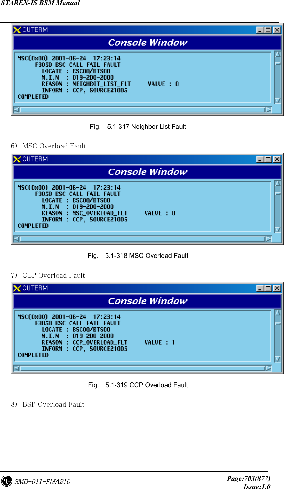
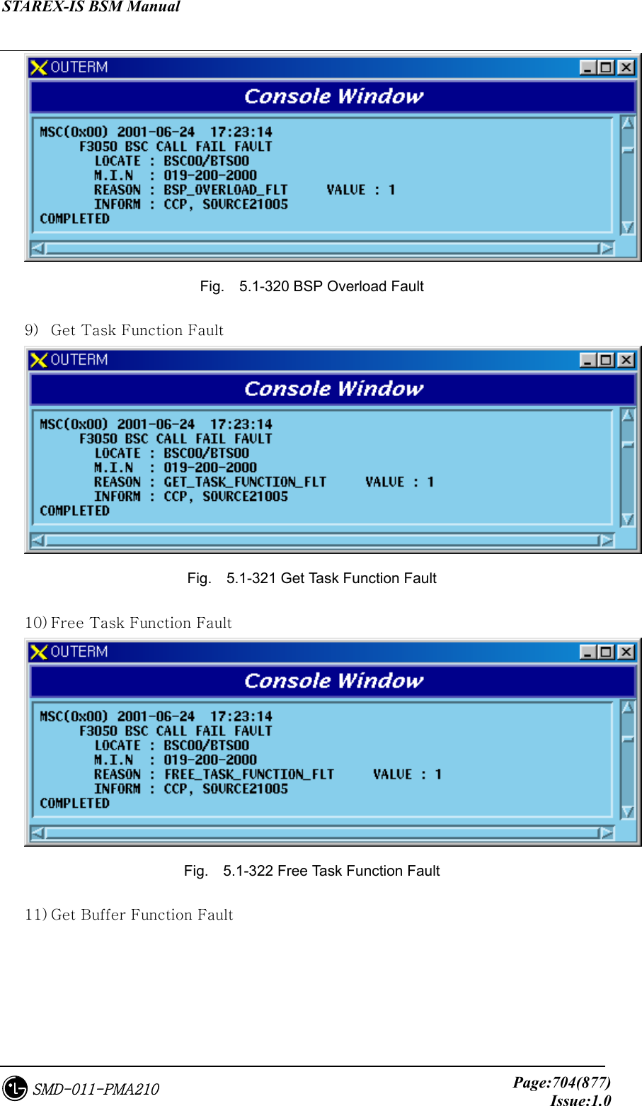

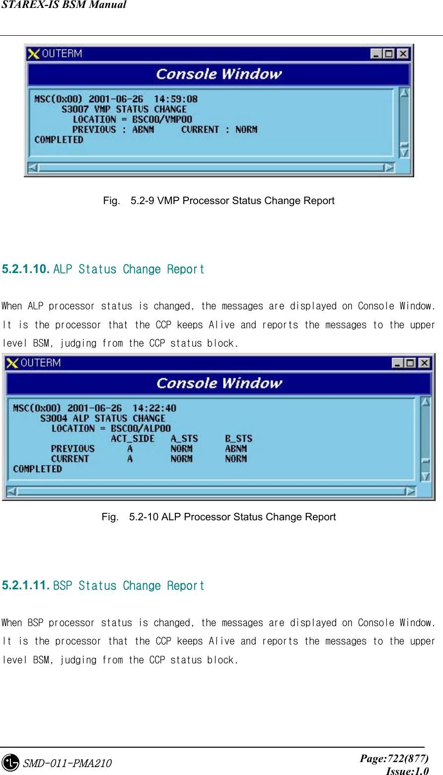
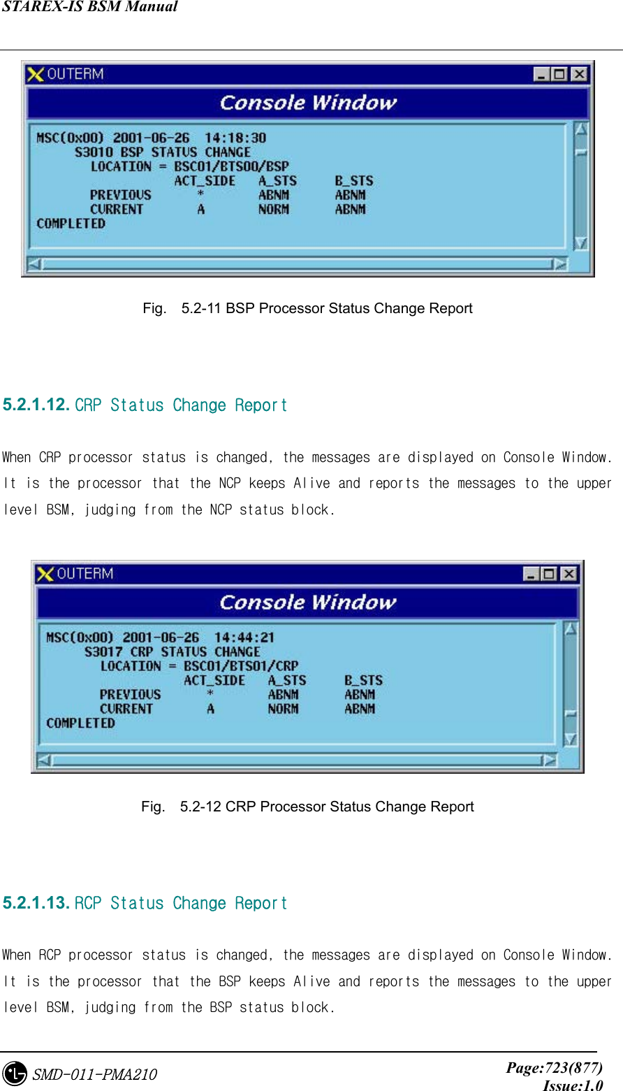
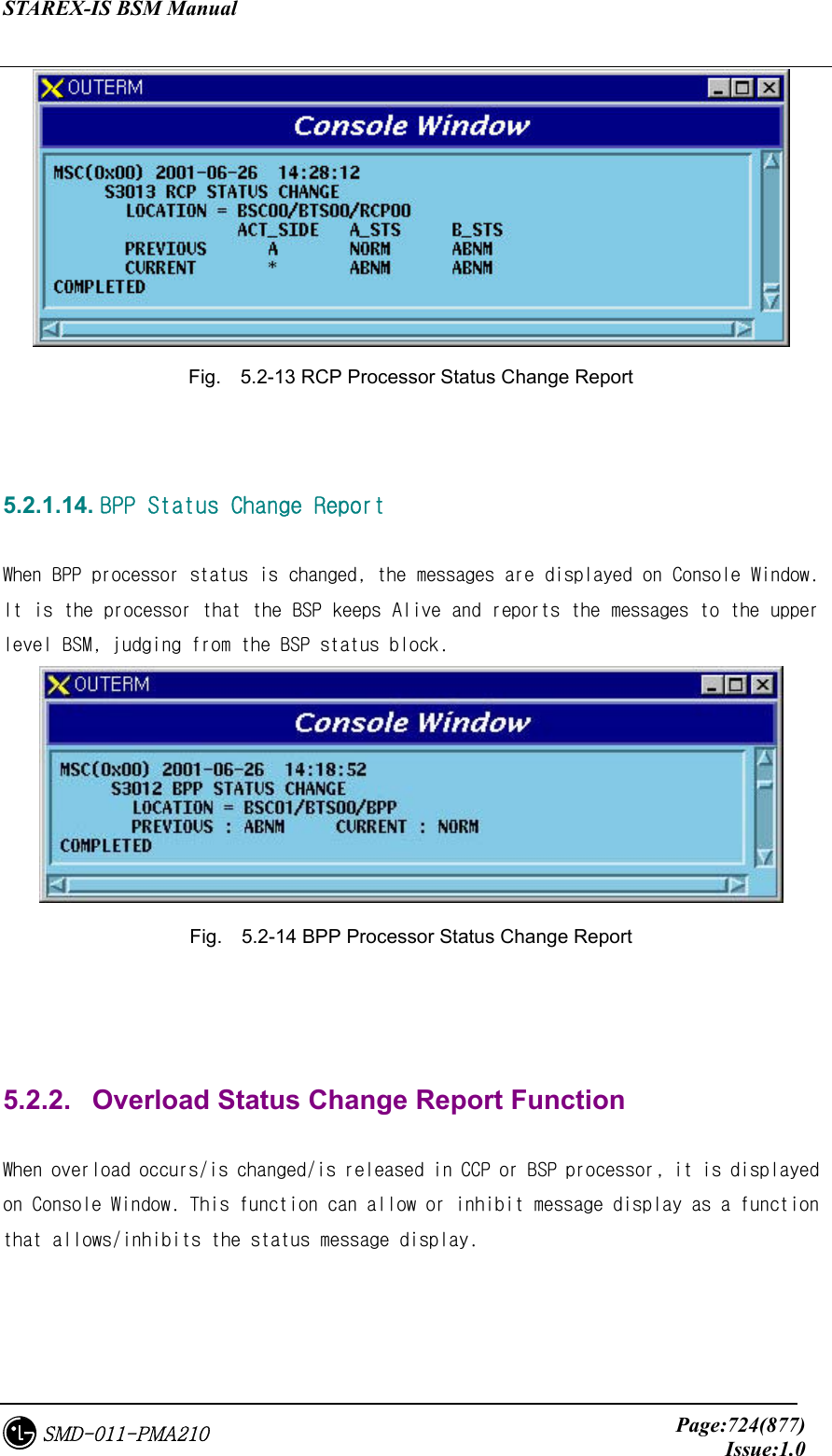
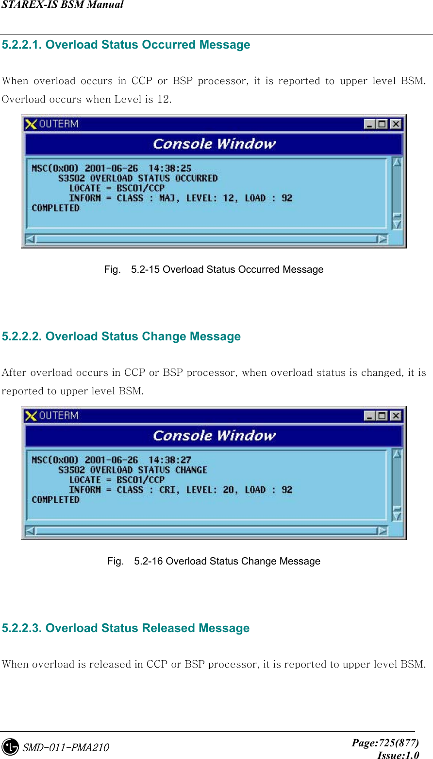
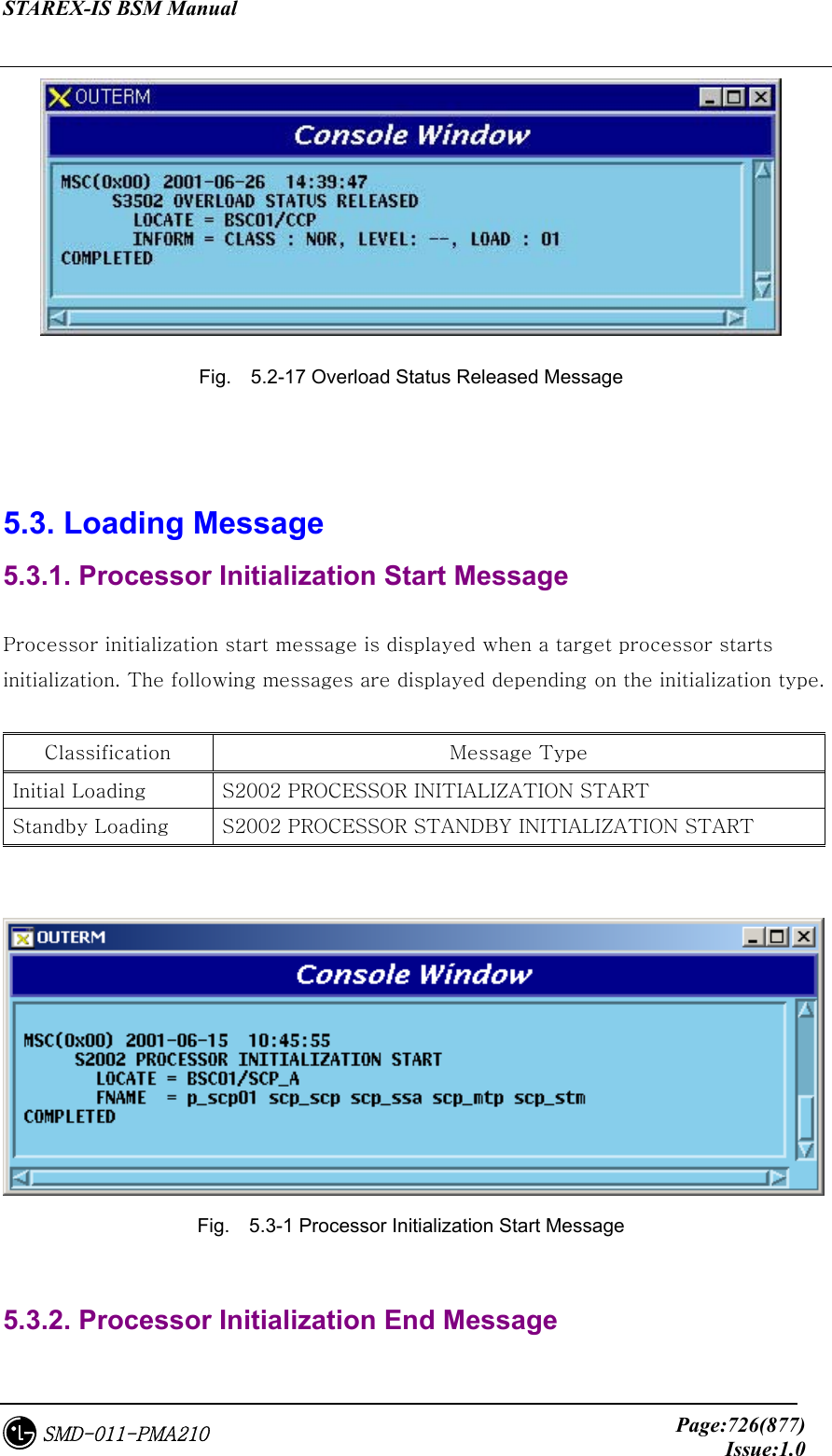
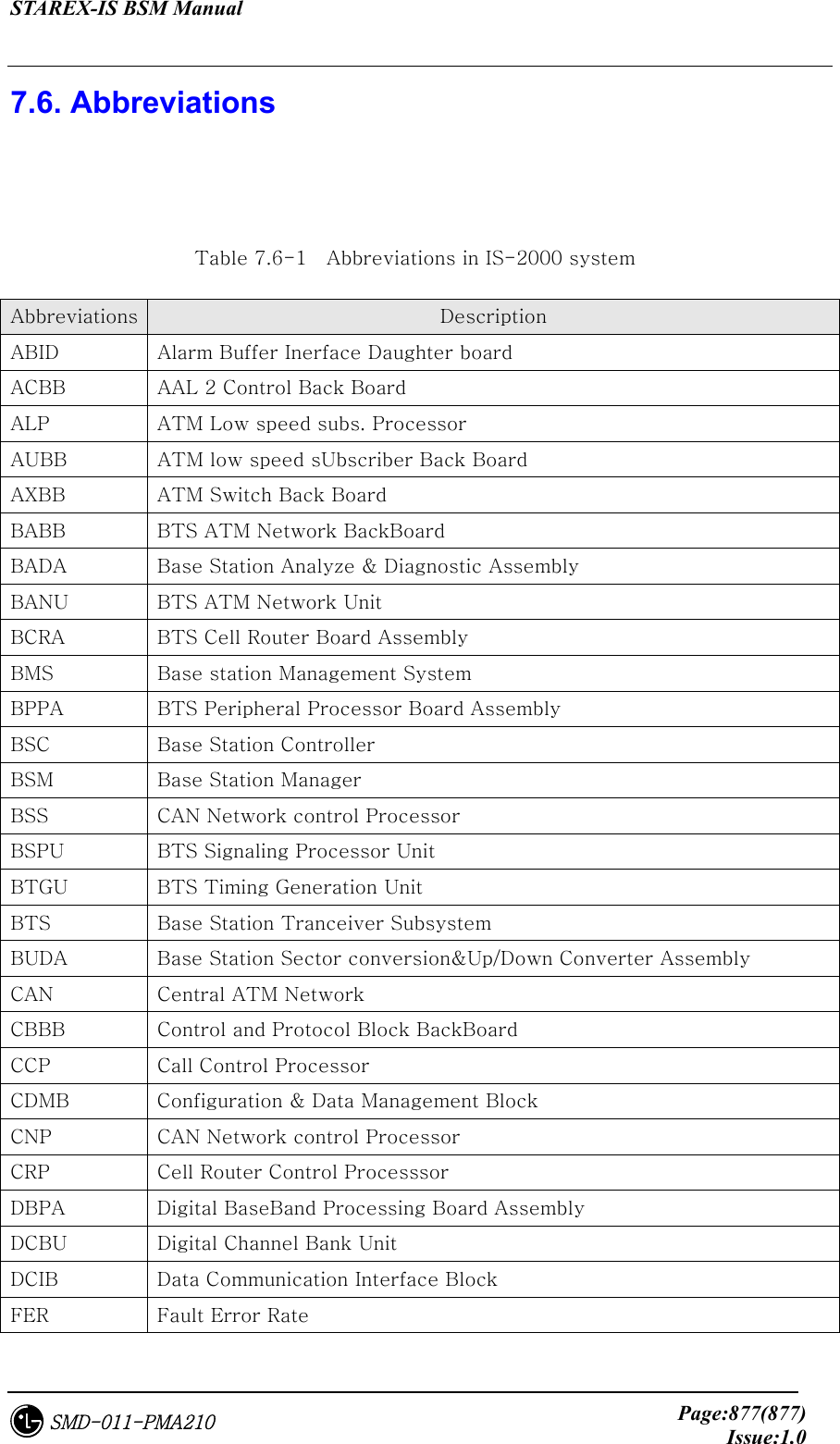
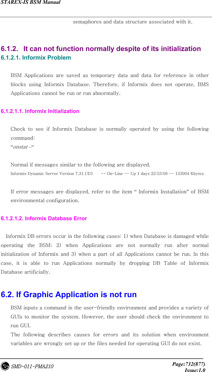
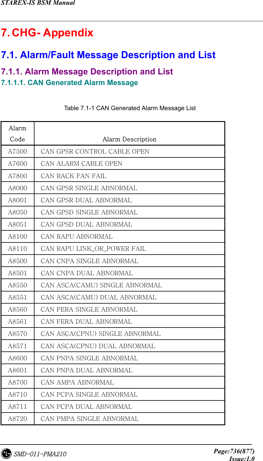
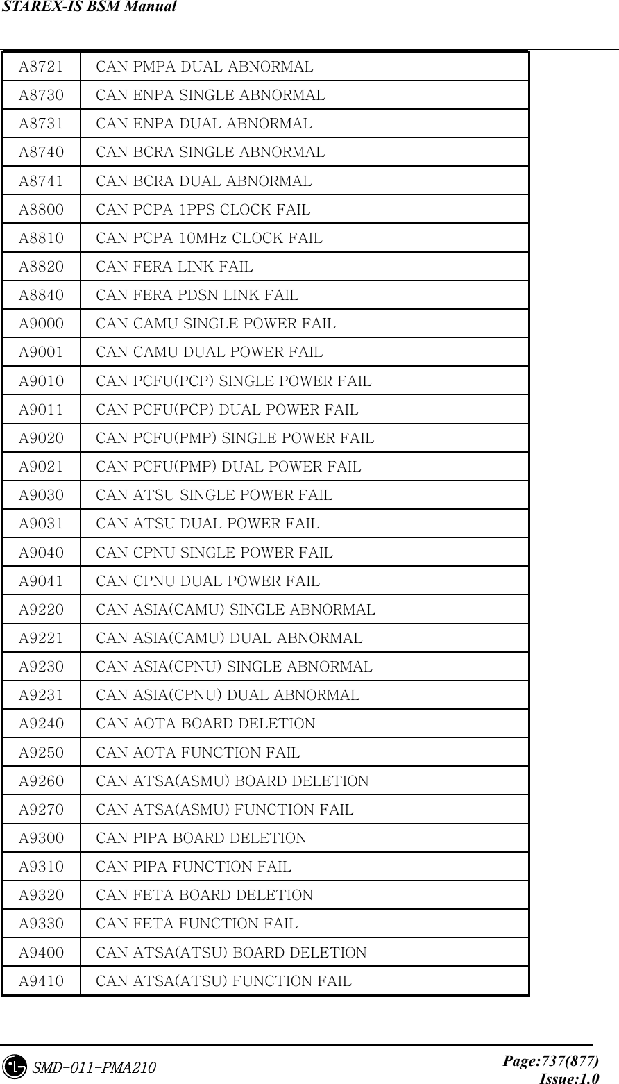
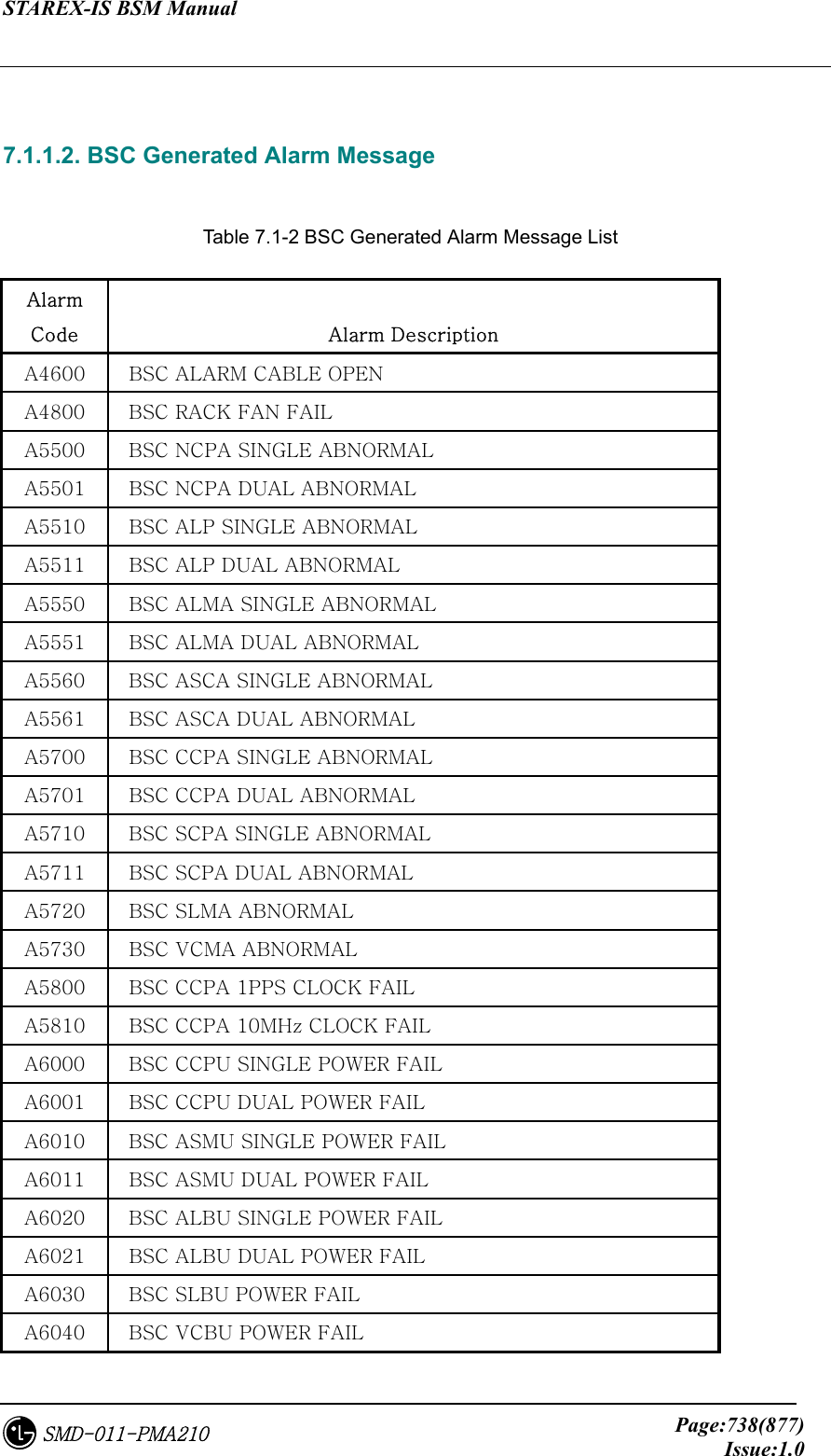
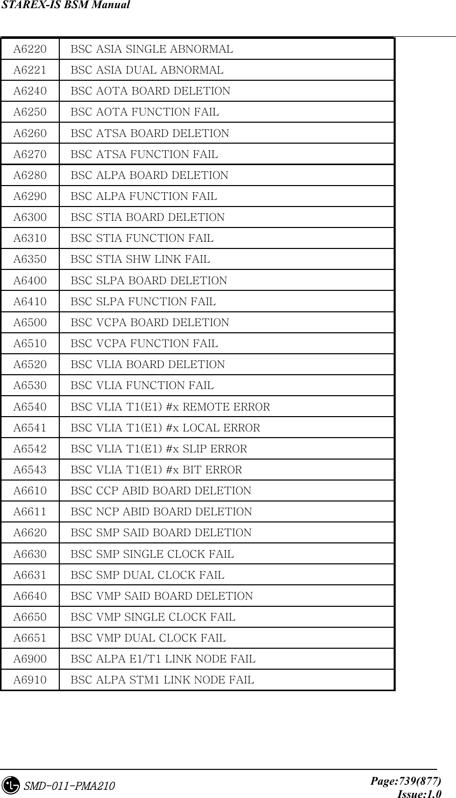
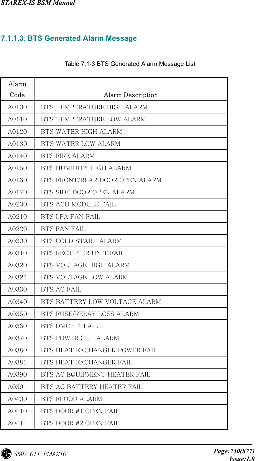
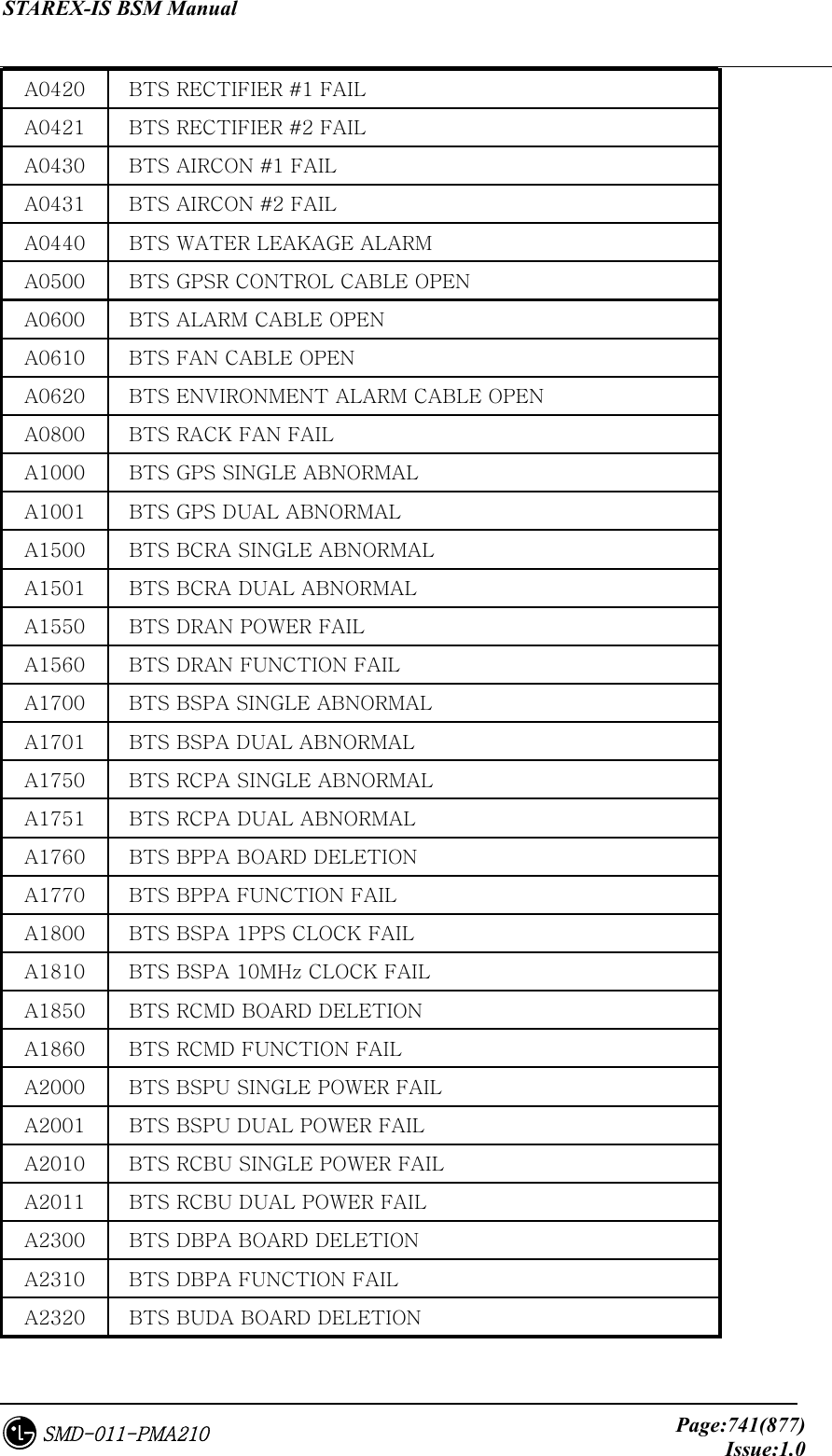
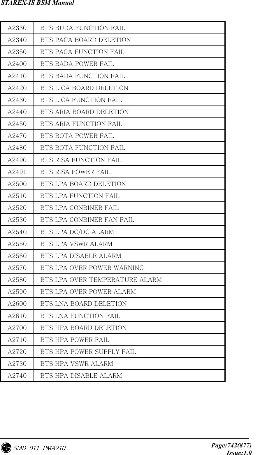
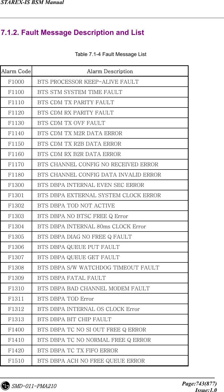
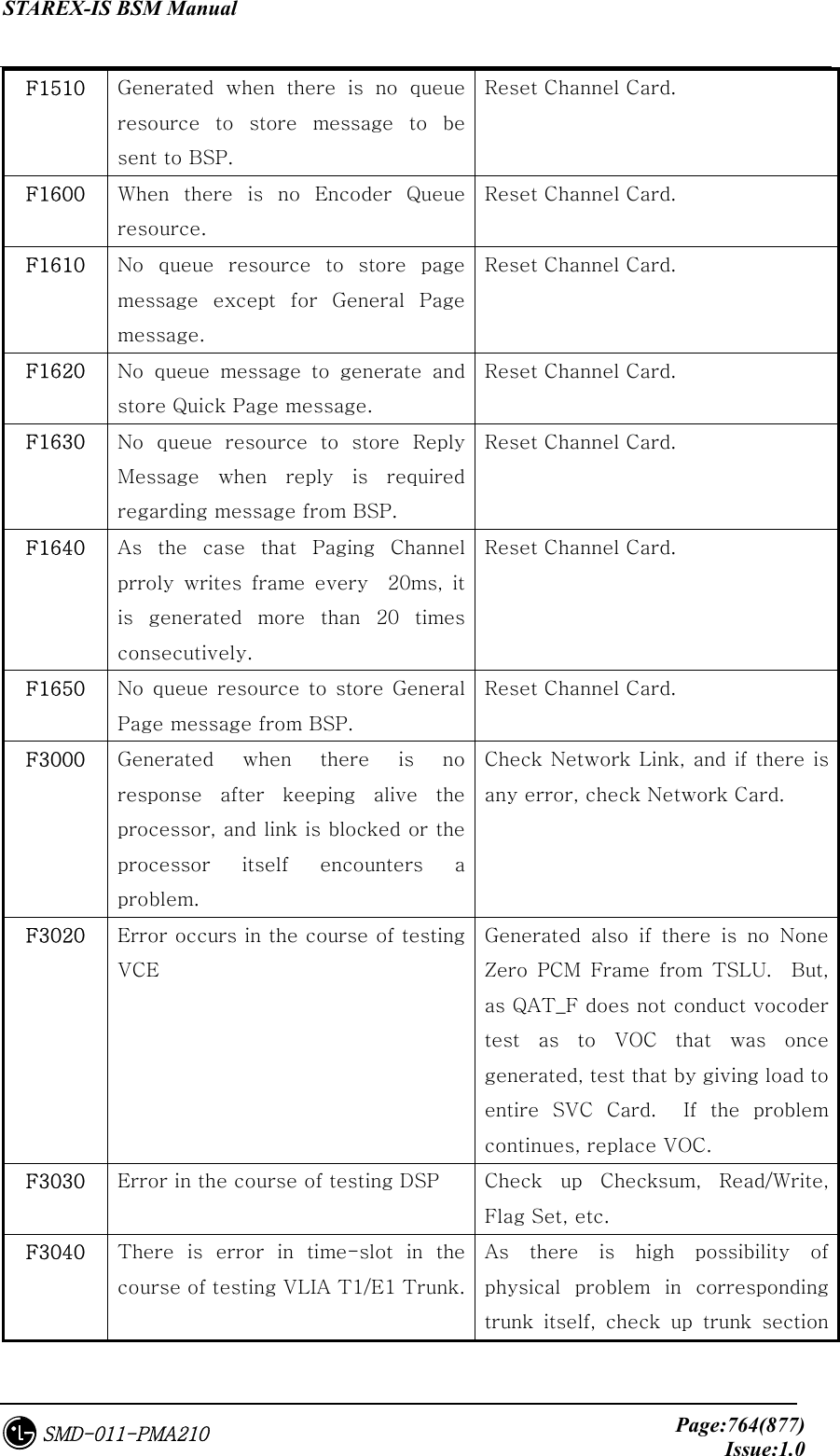
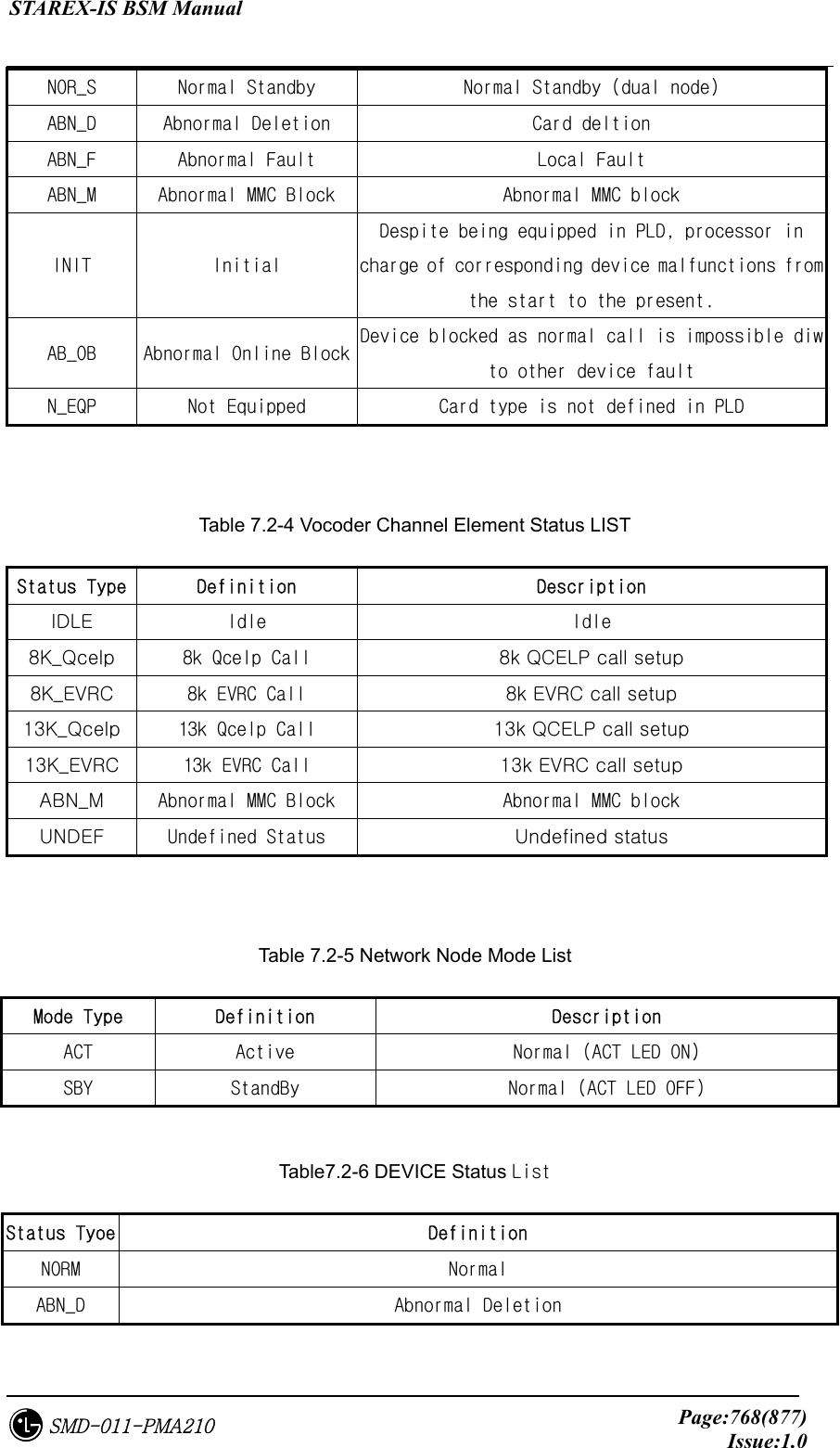
![STAREX-IS BSM Manual Page:730(877)Issue:1.0SMD-011-PMA210 6. Trouble Shoot This chapter describes problems caused by operating and solution to them. 6.1. If BSM is not operated 6.1.1. If BSM is not initialized 6.1.1.1. Shared Memory or Queue Problem 6.1.1.1.1. IPC Initialization Problem If the following messages are displayed start of MMI_server program [mmi] mmi is already in service. You can remove a file "IPCHEAD" and try again... sorry!!! The above cases can occur when BSM is already initialized and used or when the formerly executed BSM ends abnormally or by force. When these cases occur, it is possible to delete them compulsorily using rmipc command provided by BSM. However, when initializing IPC by force, perform the work after checking if it is currently in operation. (See “ Overlapped Use Problem of IPC” if UNIX ID which operated BSM previously is different from the ID currently logged in. 6.1.1.1.2. Overlapped Use Problem of IPC BSM initialization and operation can be performed by logging in as one UNIX ID. But after executing BSM by logging in as other UNIX IDs, none can reoperate BSM except the operated ID. Therefore, check Queue and Shared Memory currently in use by using UNIX command called “/usr/bin/ipcs –a” to see if other IDs operated BSM. In this case, remove the generated IPC Header and the assigned IPC by performing “rmipc” command with ID or UNIX Root authorization that operates BSM](https://usermanual.wiki/LG-Electronics-USA/3G1XOUTBTS.Users-Manual-Part-5/User-Guide-178517-Page-130.png)
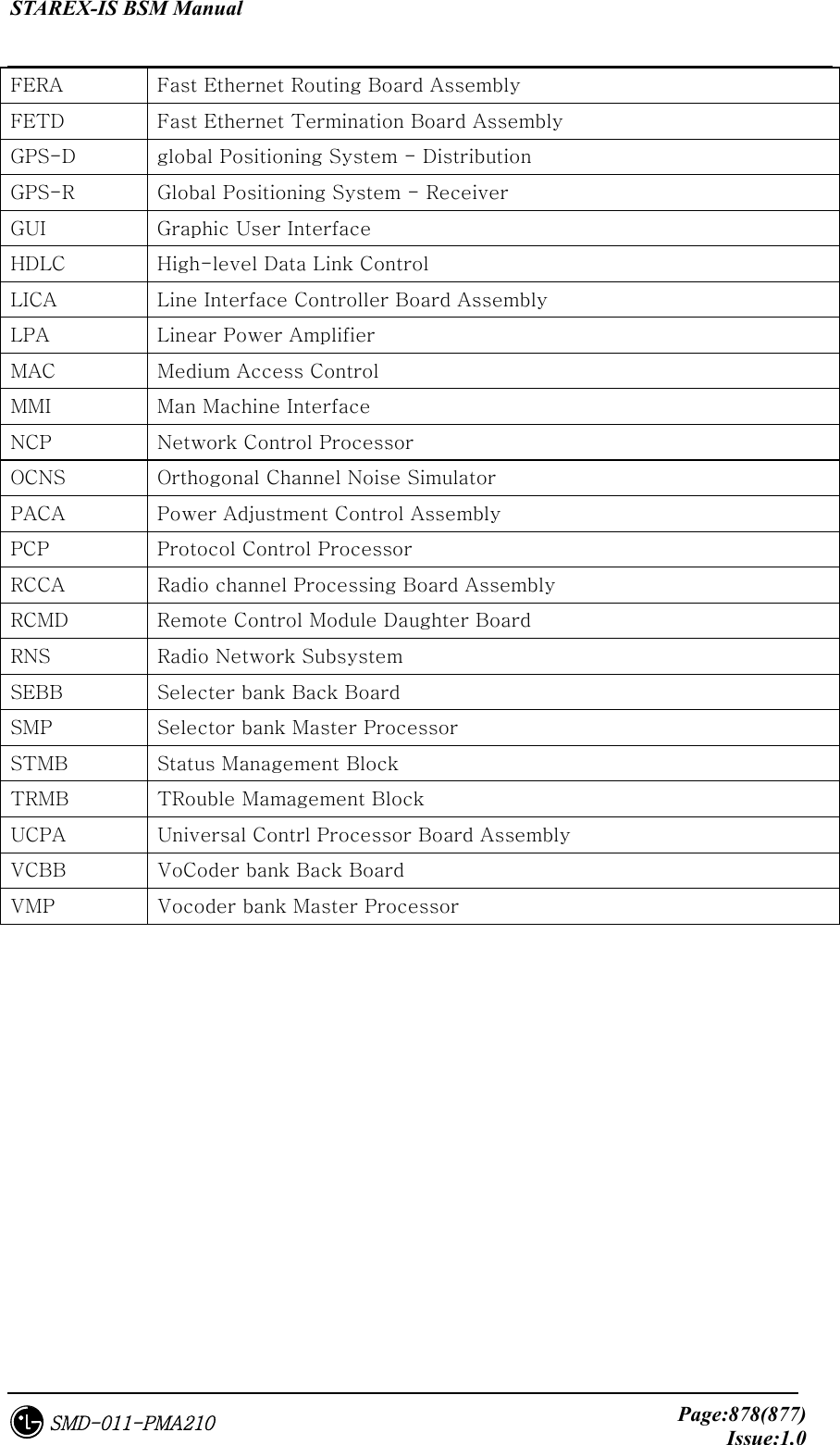
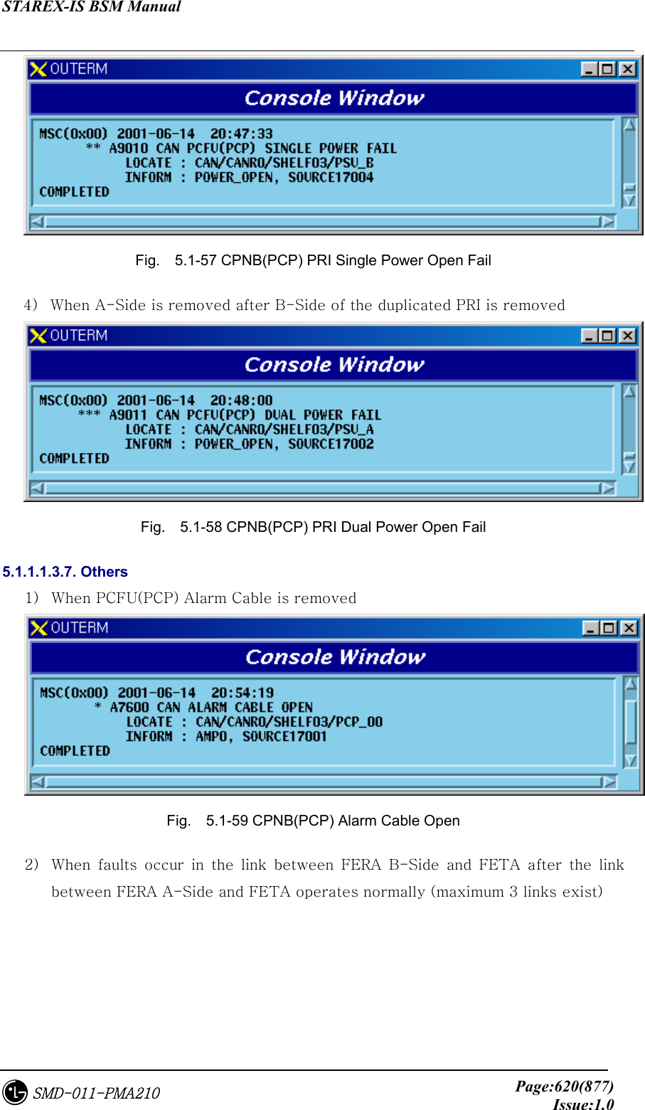
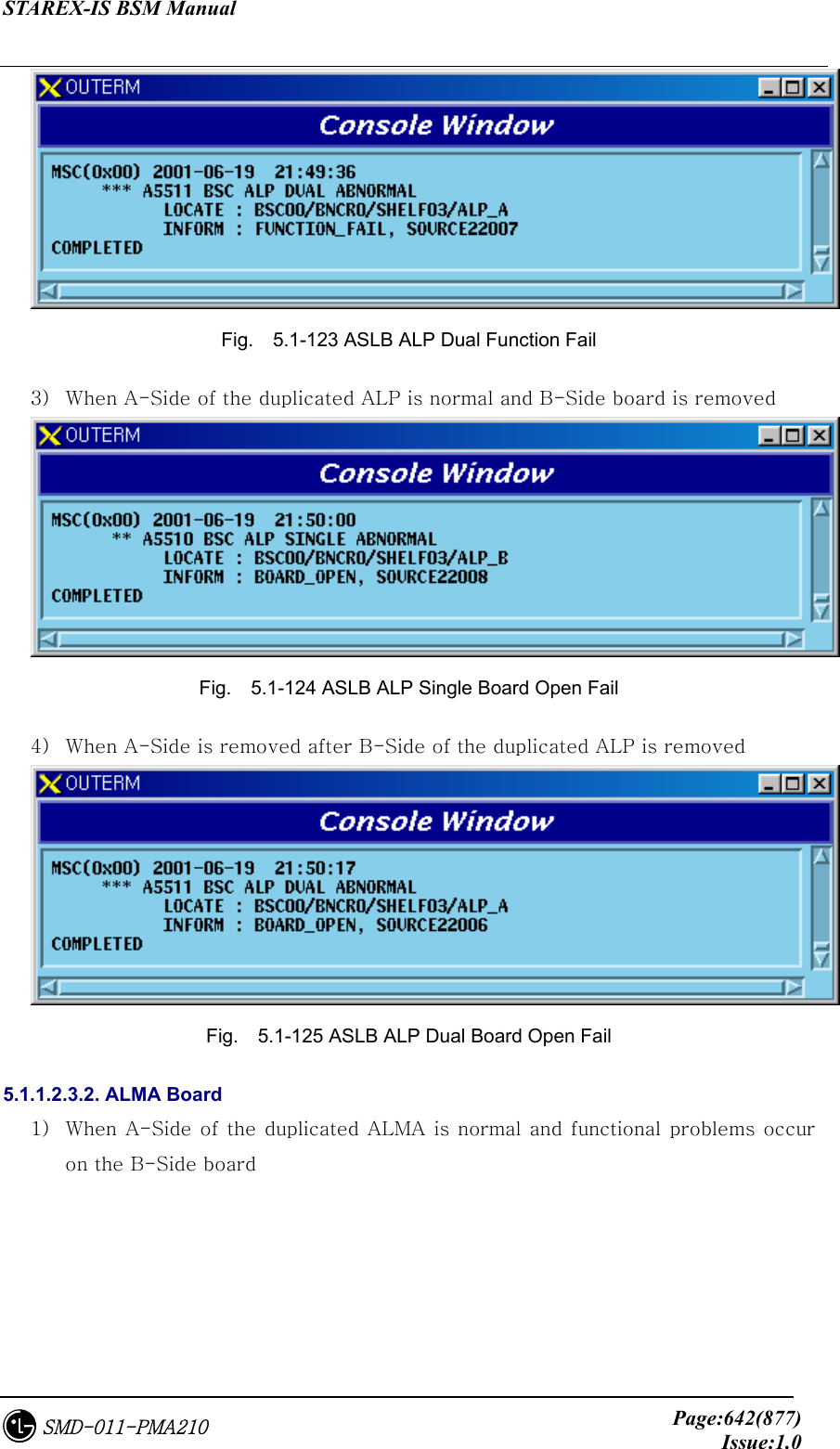
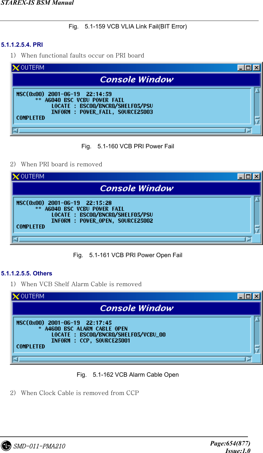
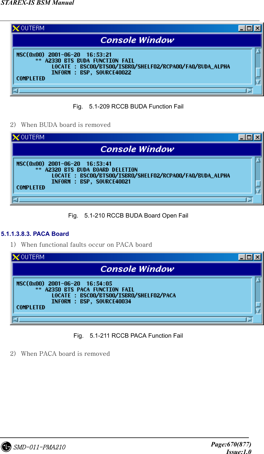
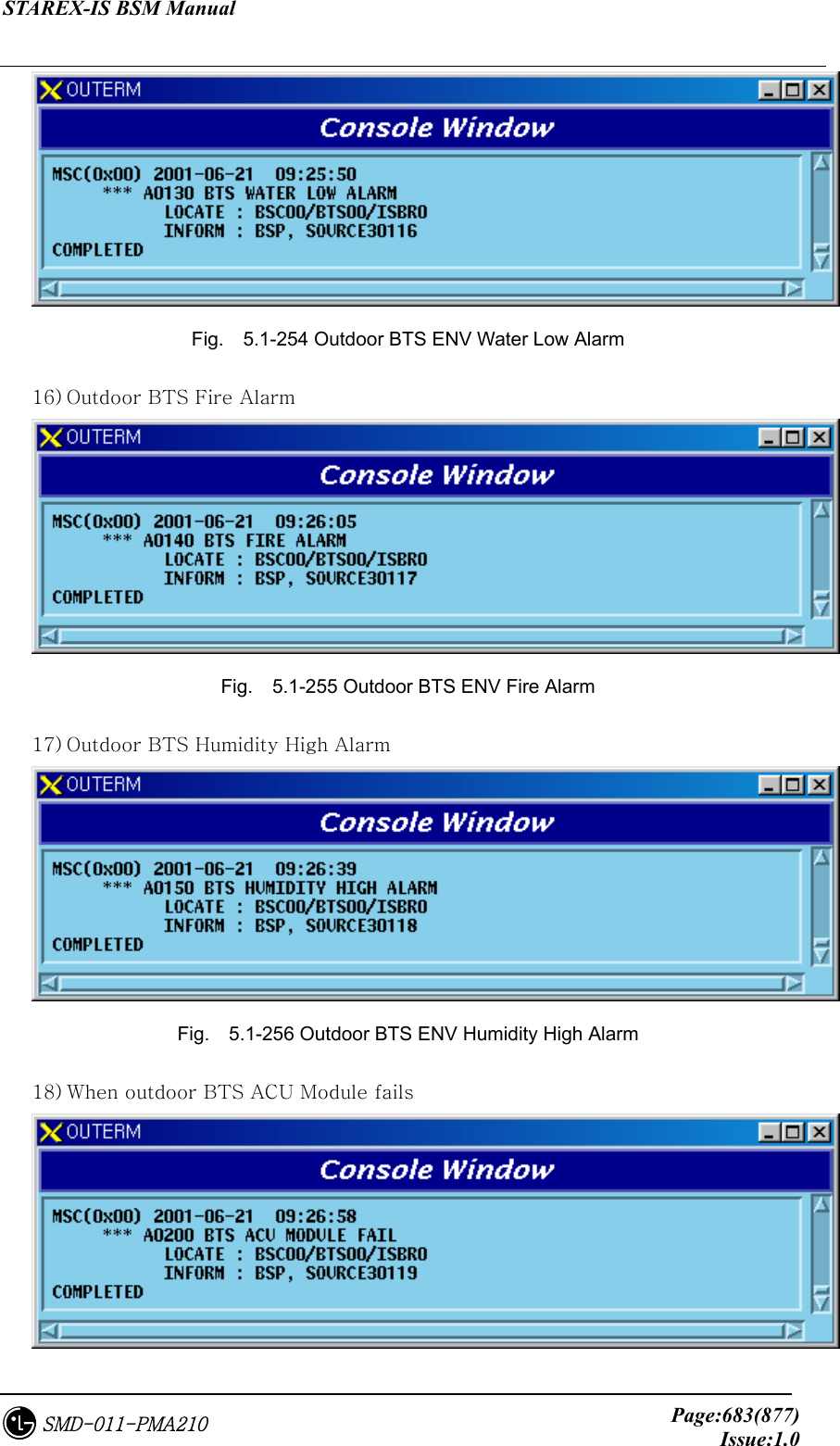
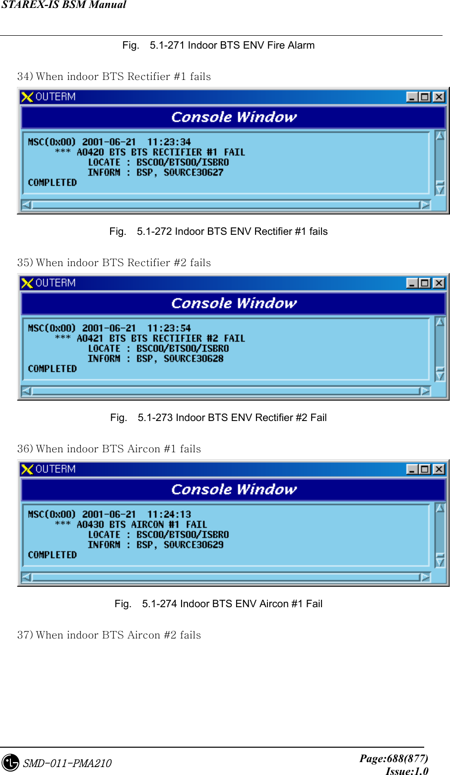
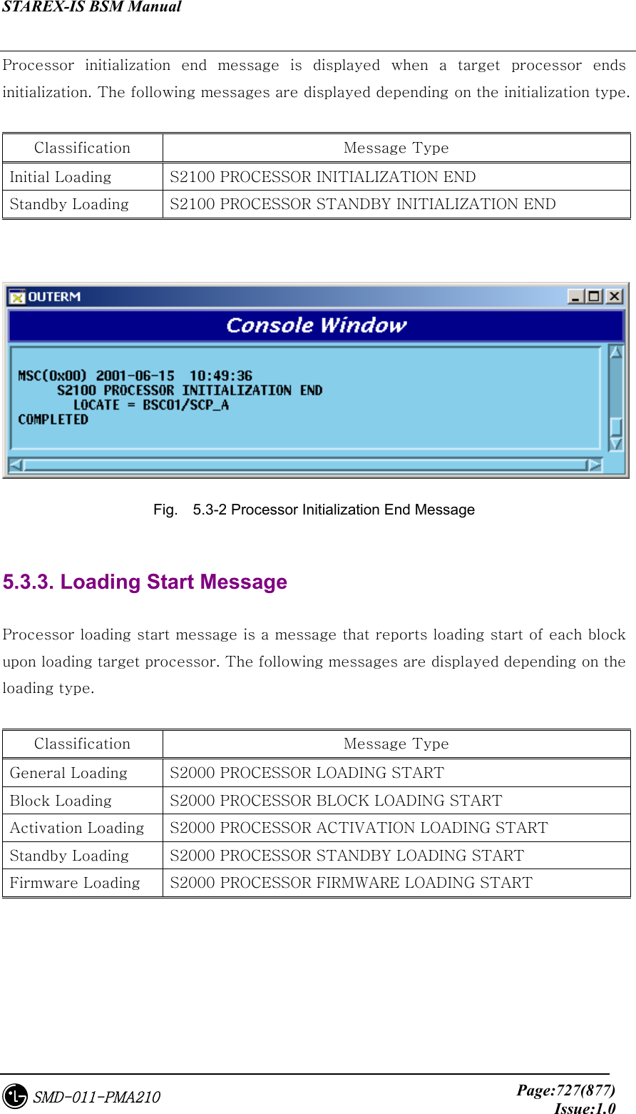
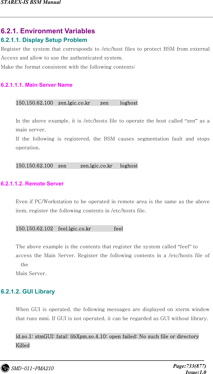
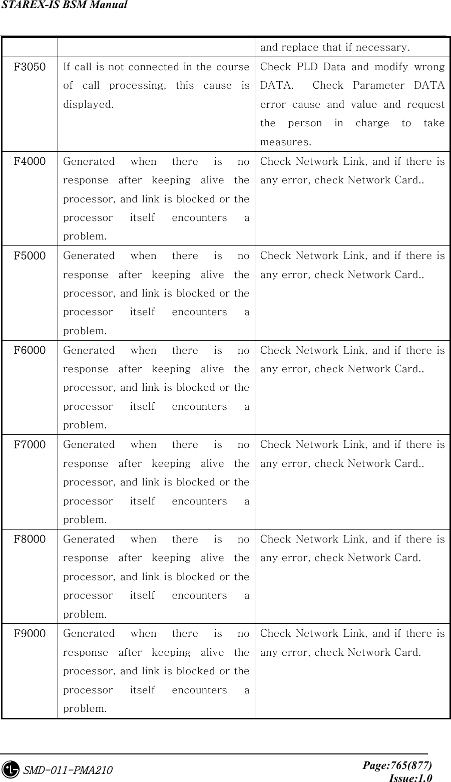
![STAREX-IS BSM Manual Page:731(877)Issue:1.0SMD-011-PMA210 6.1.1.1.3. If IPC is not deleted If IPC is not deleted by “rmipc” command to operate BSM, delete it by force through the following command. ipcrm [ -m shmid ] [ -q msqid ] [ -s semid ] [ -M shmkey ] [ -Q msgkey ] [ -S semkey ] Description of each factor -m shmid Remove the shared memory identWhenier shmid from the system. The shared memory segment and data struc- ture associated with it are destroyed after the last detach. -q msqid Remove the message queue identWhenier msqid from the system and destroy the message queue and data structure associated with it. -s semid Remove the semaphore identWhenier semid from the system and destroy the set of semaphores and data structure associated with it. -M shmkey Removes the shared memory identWhenier, created with key shmkey, from the system. The shared memory segment and data structure associated with it are destroyed after the last detach. -Q msgkey Remove the message queue identWhenier, created with key msgkey, from the system and destroy the mes- sage queue and data structure associated with it. -S semkey Remove the semaphore identWhenier, created with key semkey, from the system and destroy the set of](https://usermanual.wiki/LG-Electronics-USA/3G1XOUTBTS.Users-Manual-Part-5/User-Guide-178517-Page-131.png)
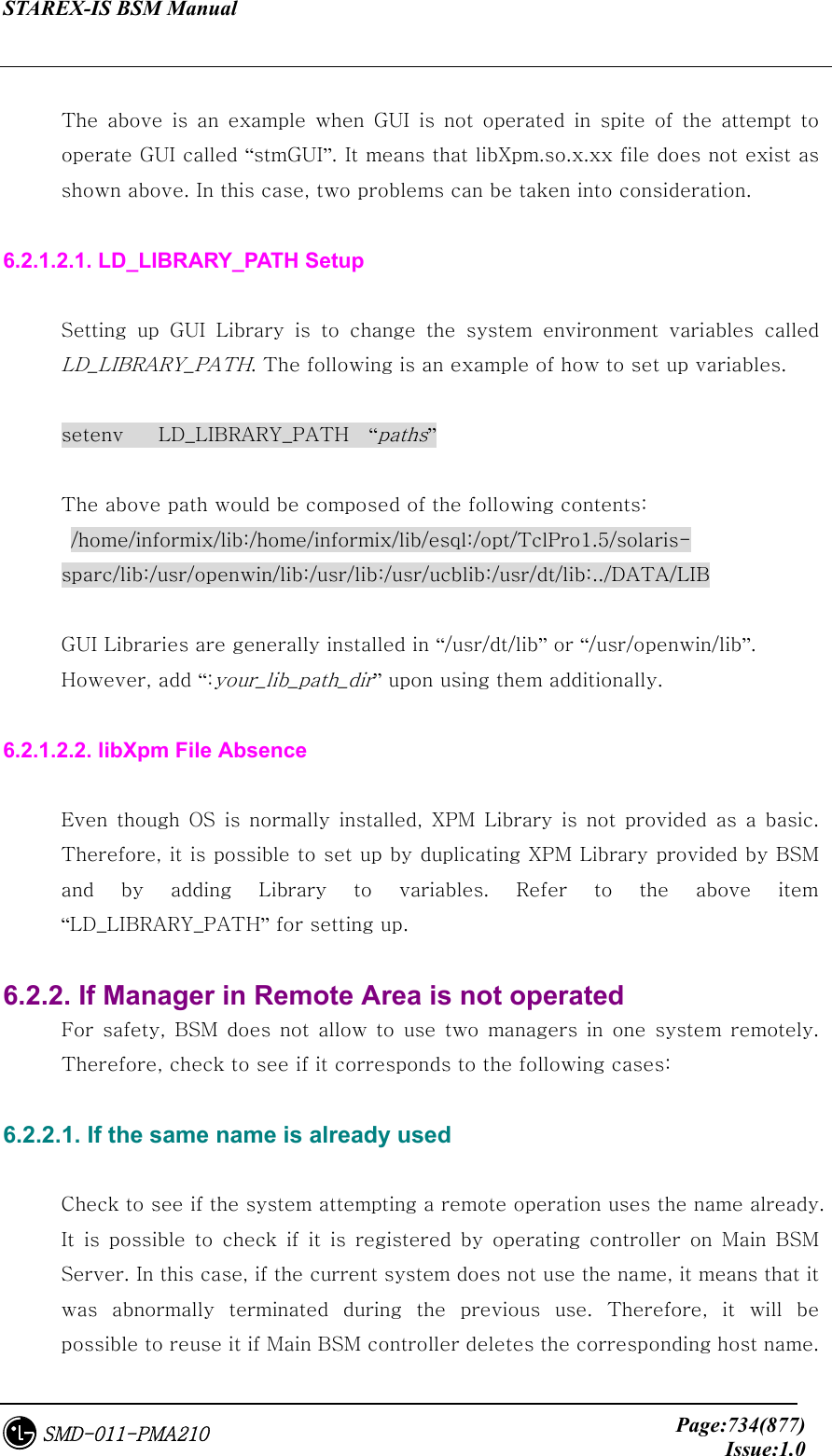
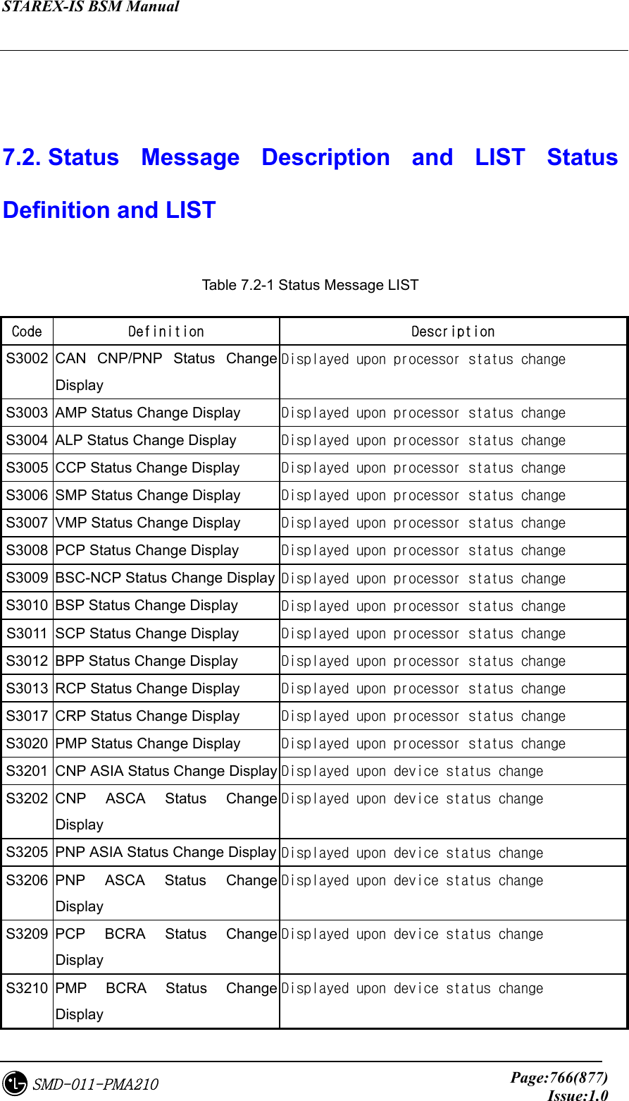
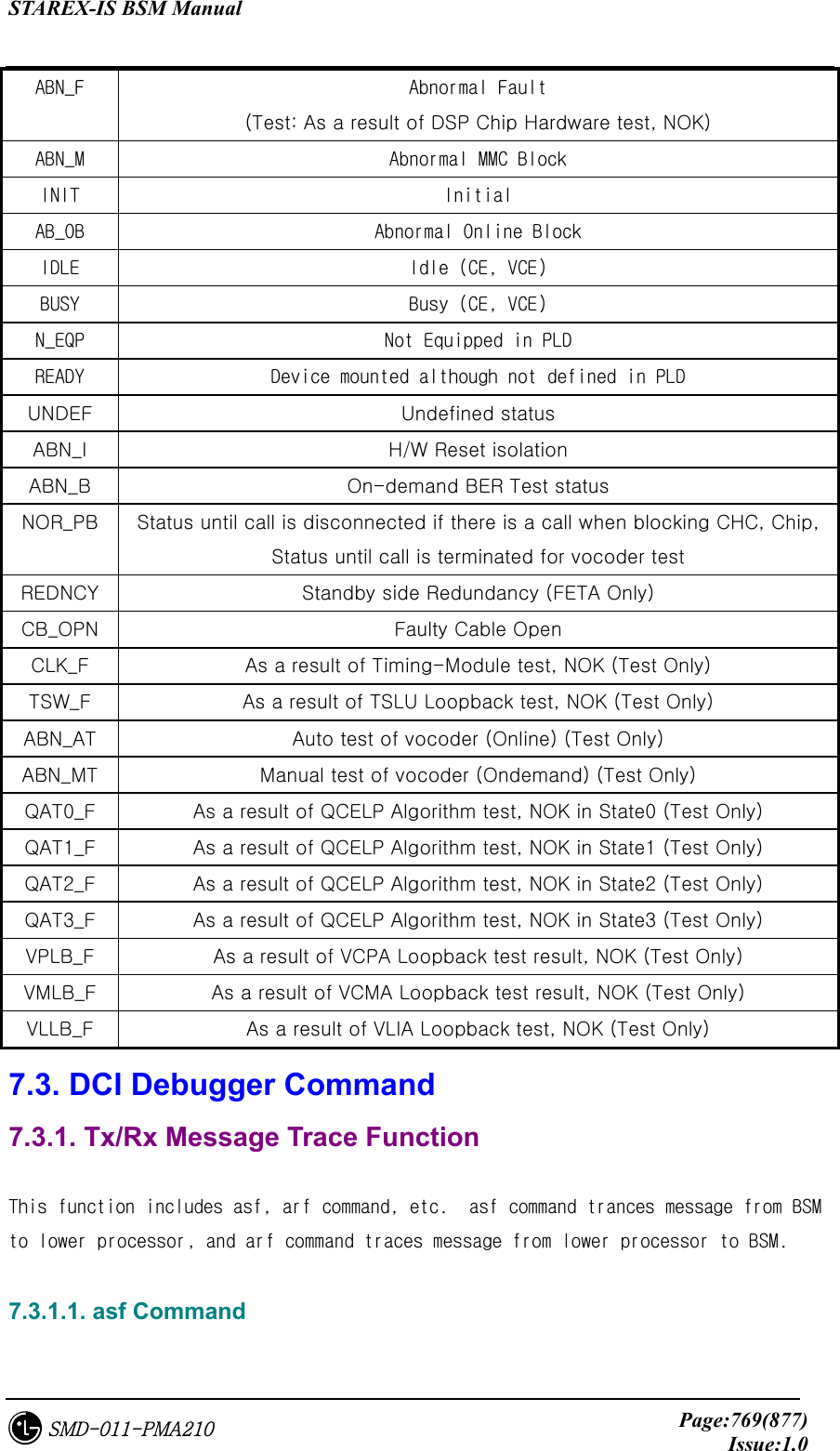
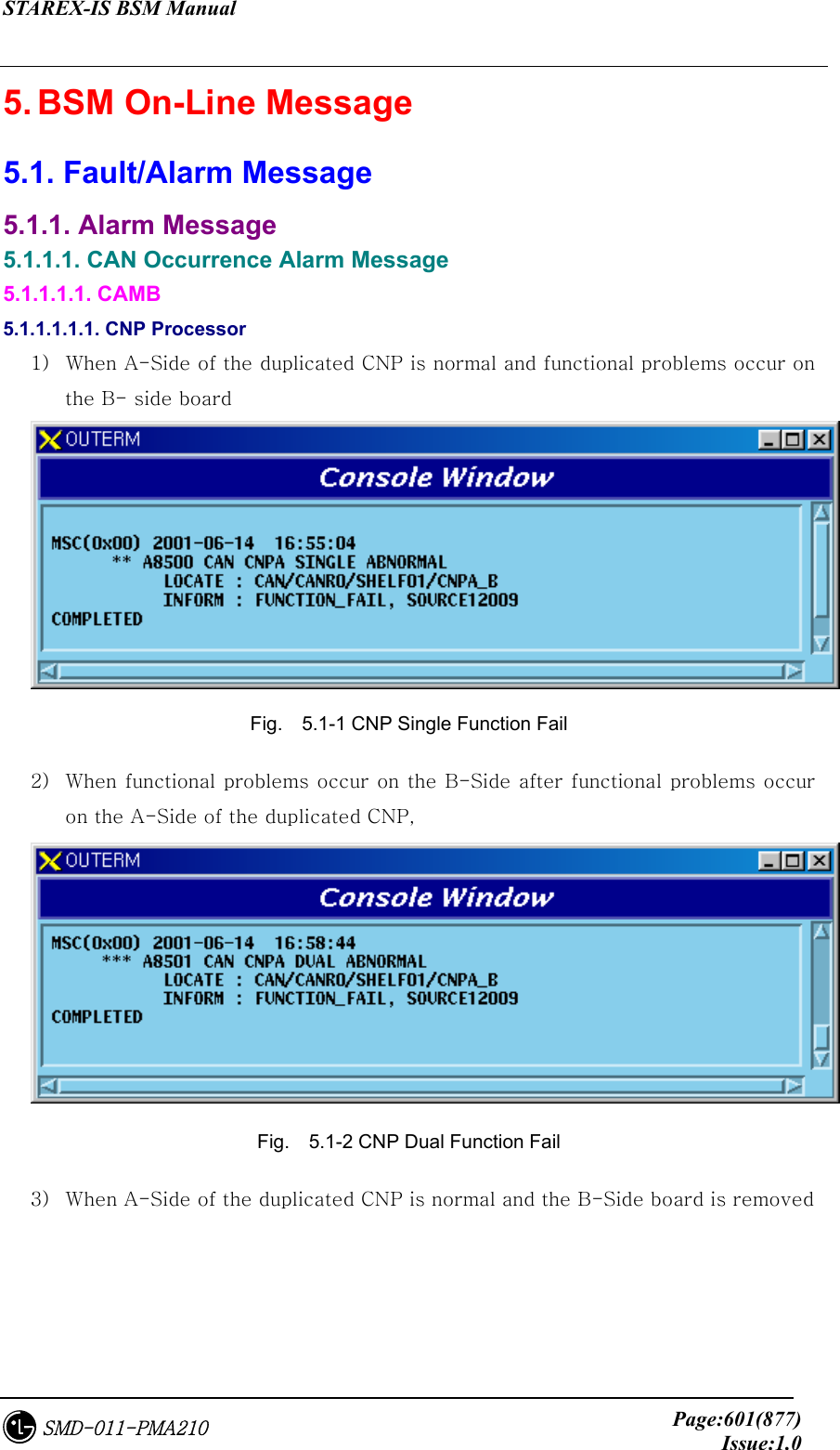
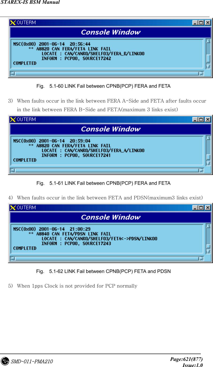
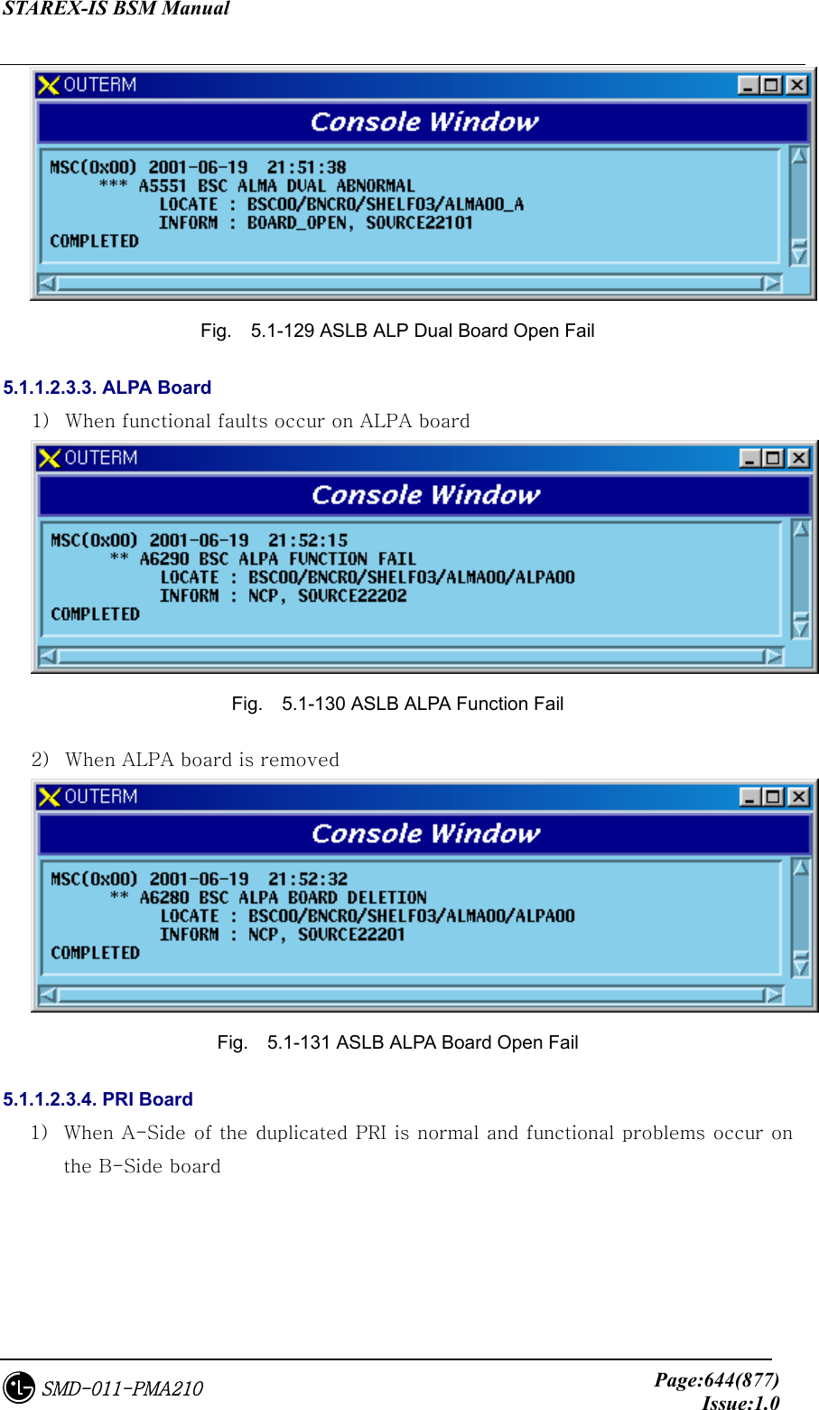
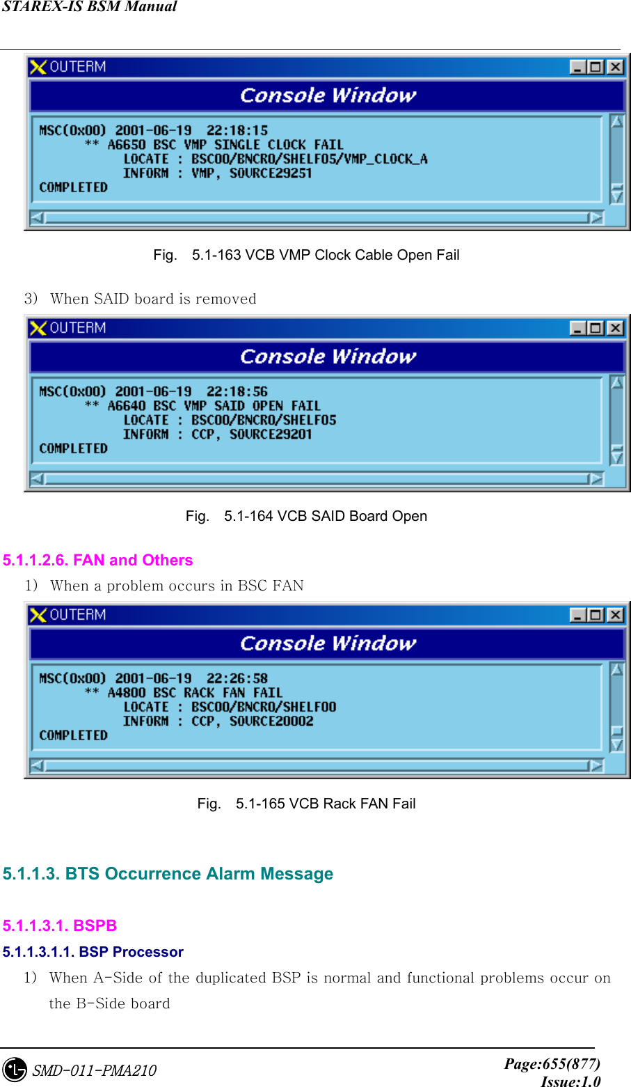
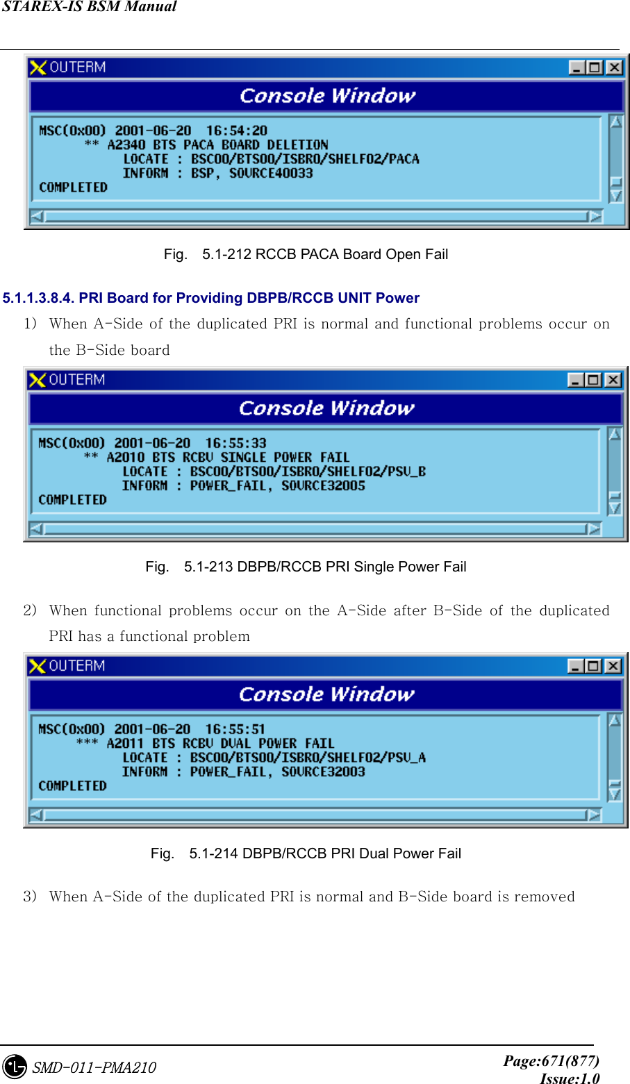
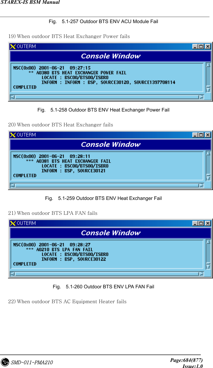
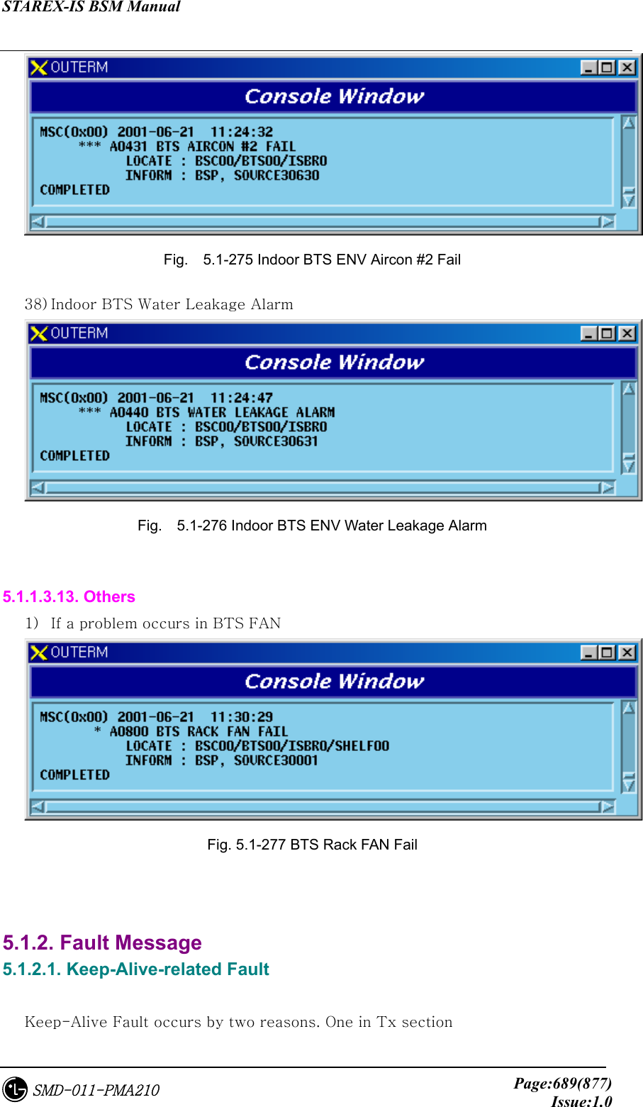
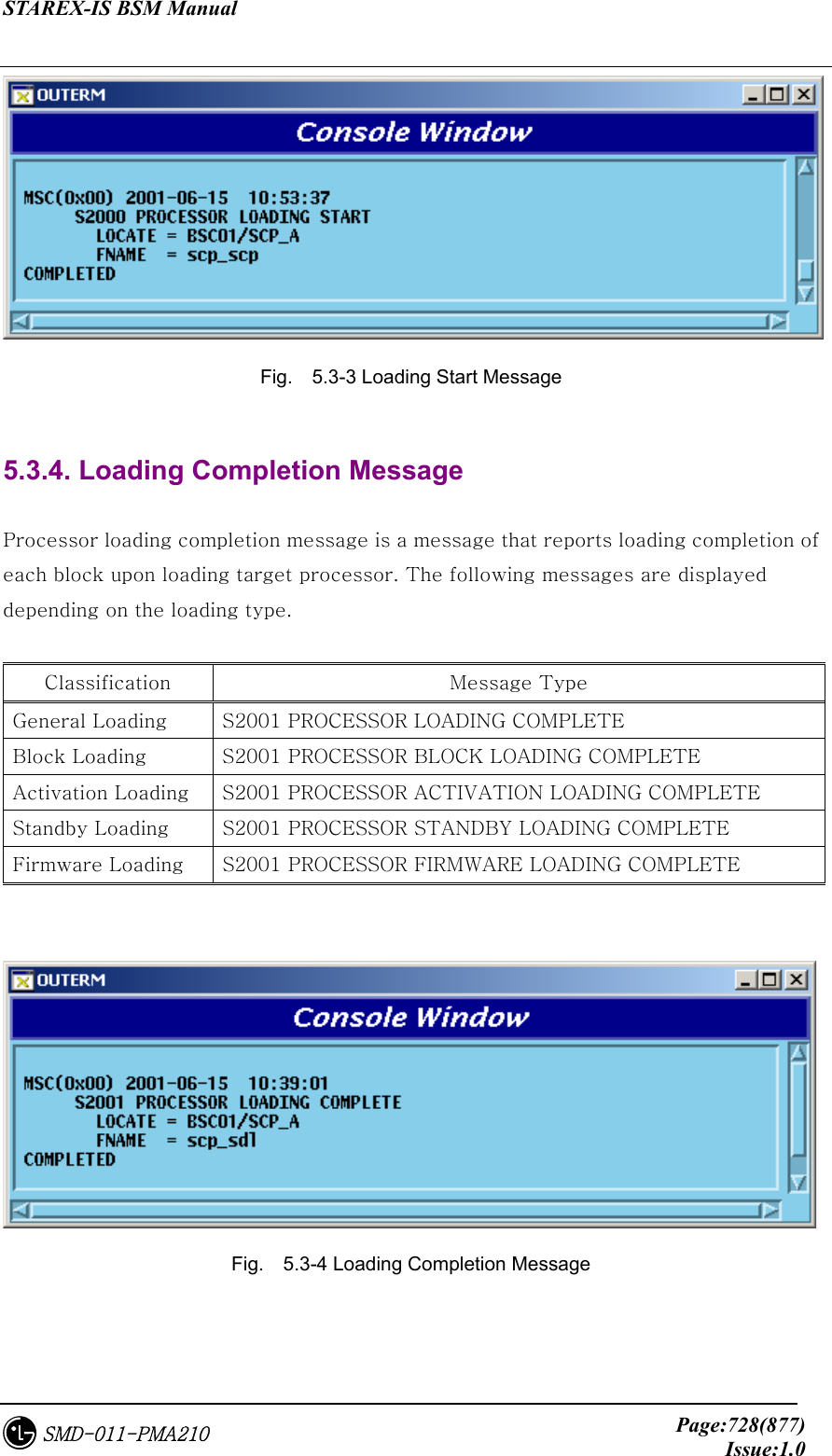
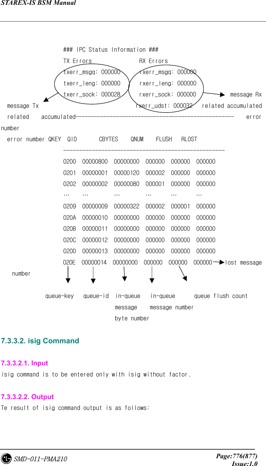
![STAREX-IS BSM Manual Page:770(877)Issue:1.0SMD-011-PMA210 7.3.1.1.1. Input asf [all/off] : If a factor is not set in asf command, or as a factor, all is set, it can trace all messages from BSM. It can stop Tx message trace set to asf off command. asf sigid [dstaddr] : It can be used to trace only Tx message to specific IP or specific signal ID value without tracing all messages. To trace specific signal ID to all targets, it is used in the form of asf sigid, and to trace specific signal ID to specific target, it can be used in the form of asf sigid dstaddr. Here, dstaddr can set a factor in the form of hexadecimal 32bit-word value or dotted-decimal. asf ffff dstaddr : It can be used to trace all signals to specific IP. Likewise, IP address is set in the form of 32bit-word or dotted-decimal. 7.3.1.1.2. Output Message traced by asf command has the following output format. The output contents are message Tx time and message header information.](https://usermanual.wiki/LG-Electronics-USA/3G1XOUTBTS.Users-Manual-Part-5/User-Guide-178517-Page-170.png)
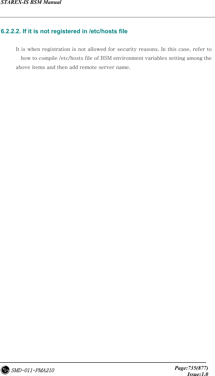
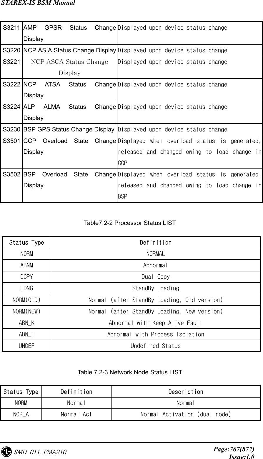
![STAREX-IS BSM Manual Page:771(877)Issue:1.0SMD-011-PMA210 Message Tx time => ASF(qid:5101) at Fri Feb 2 10:40:25 2001 Msg_flag [0xF634] Msg_len [0028] Message length Src_IP [0x1DC00001] Dest_IP [0x11400101] Dest(target) Src_TID [000682] Dest_TID [000000] IP & Task ID Remain_conn [FALSE ] Sig_id [0x0A66] signal ID Remain_time [00 sec] Src(BSM) IP and Task ID 7.3.1.2. arf Command 7.3.1.2.1. Input arf [all/off] : This can trace all messages received to BSM if a factor is not set in arf command, or all is set as factor. IT can stop tracing Rx message set as arf off command. arf sigid [srcaddr] : Without tracing all messages, this can be used only to trace specific signal ID value or Rx message from specific IP. To trace specific signal ID from all targets, it is ued in the form of arf sigid, and to trace specific signal ID from specific target, it can be used in the form of arf sigid srcaddr. Here, srcaddr can set a factor in the form of hexademical 32bit-word value or dotted-decimal. asf ffff srcaddr : This is to trace all signals from specific IP. Likewise, IP address is set in the form of 32bit-word or dotted-decimal. 7.3.1.2.2. Output Message traced by arf command has the following output format. The output contents are message Tx time and message header information.](https://usermanual.wiki/LG-Electronics-USA/3G1XOUTBTS.Users-Manual-Part-5/User-Guide-178517-Page-171.png)
 at Fri Feb 2 10:40:25 2001 Msg_flag [0xF634] Msg_len [0225] Message length Src_IP [0x11400201] Dest_IP [0x1DC00001] Dest(BSM) Src_TID [000074] Dest_TID [000000] IP & Task ID Remain_conn [FALSE ] Sig_id [0x0A65] Signal ID Remain_time [00 sec] Src(Target) IP & Task ID](https://usermanual.wiki/LG-Electronics-USA/3G1XOUTBTS.Users-Manual-Part-5/User-Guide-178517-Page-172.png)
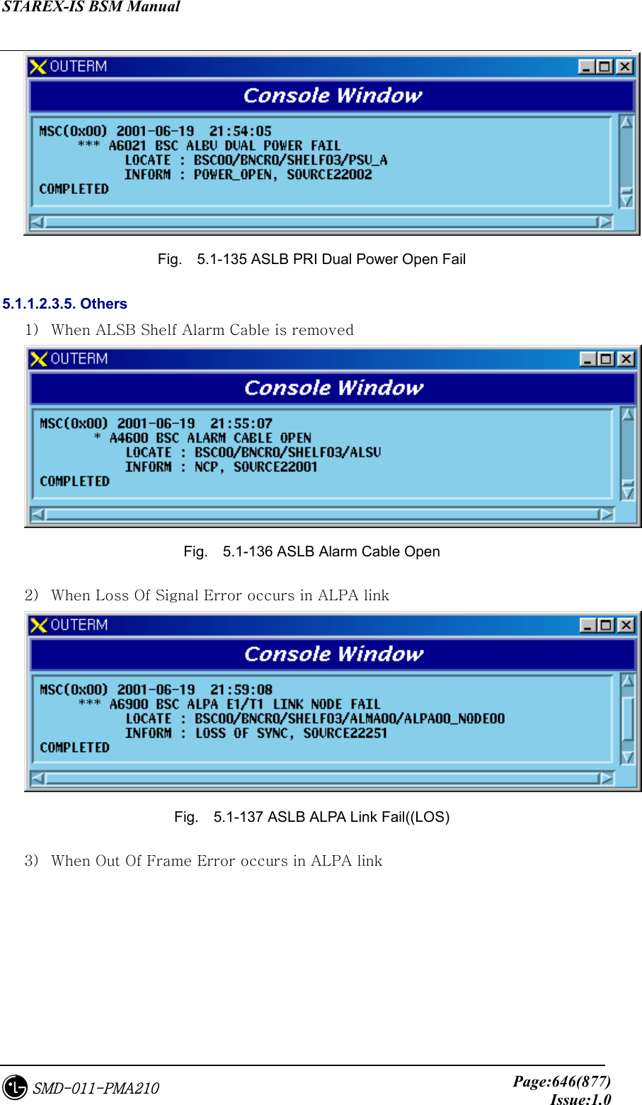
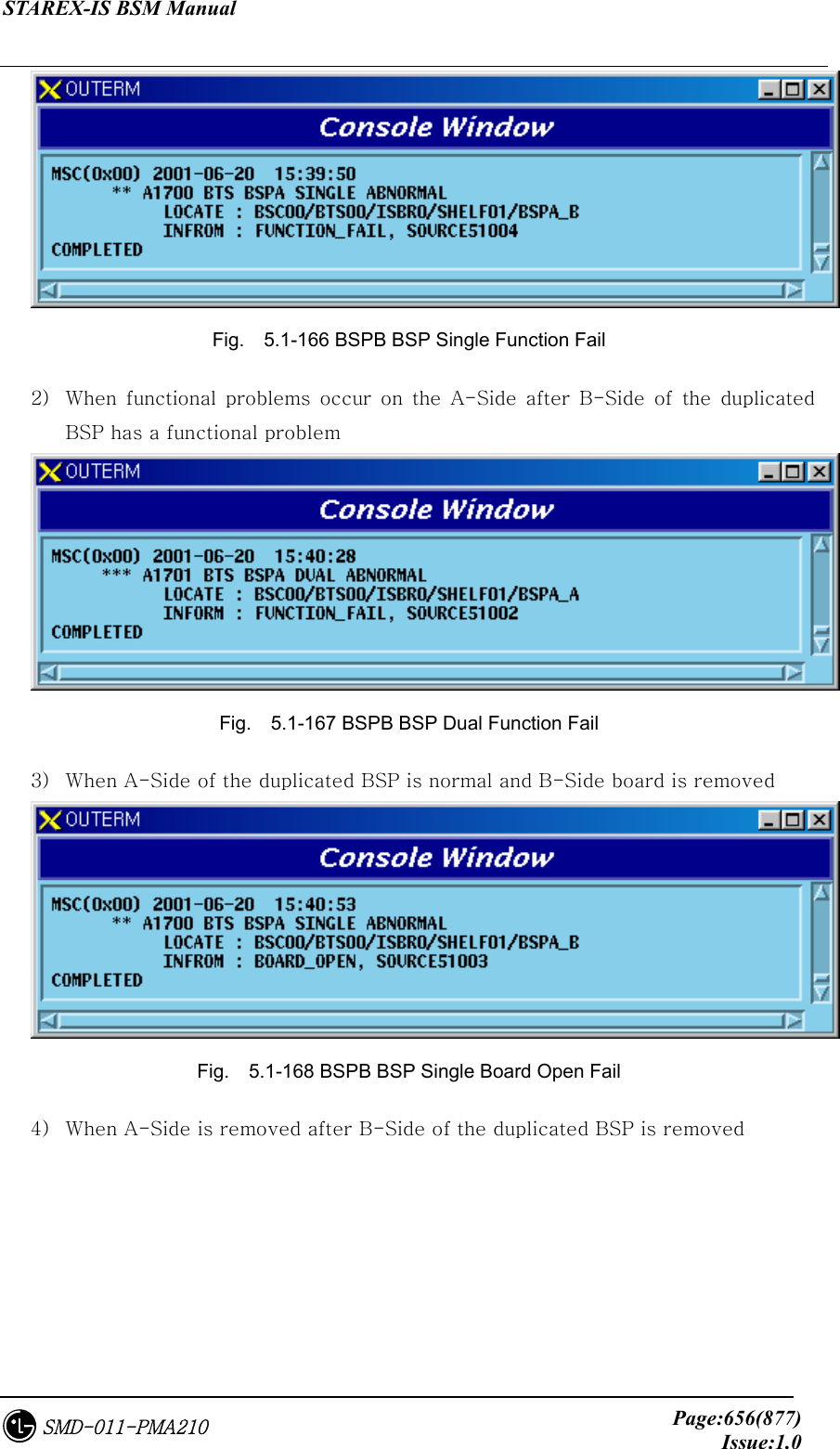
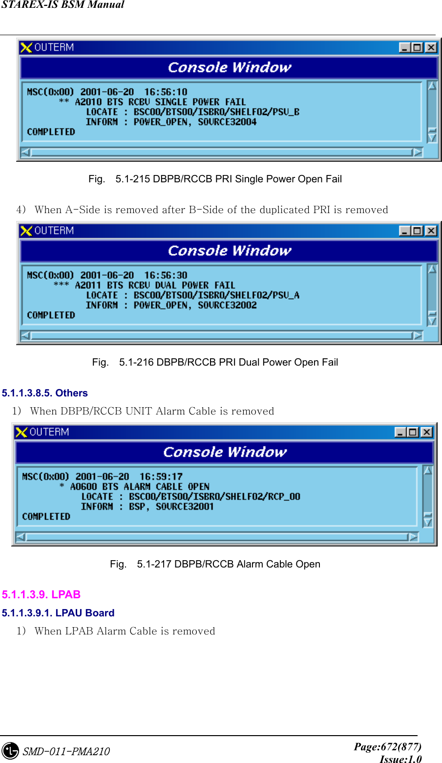
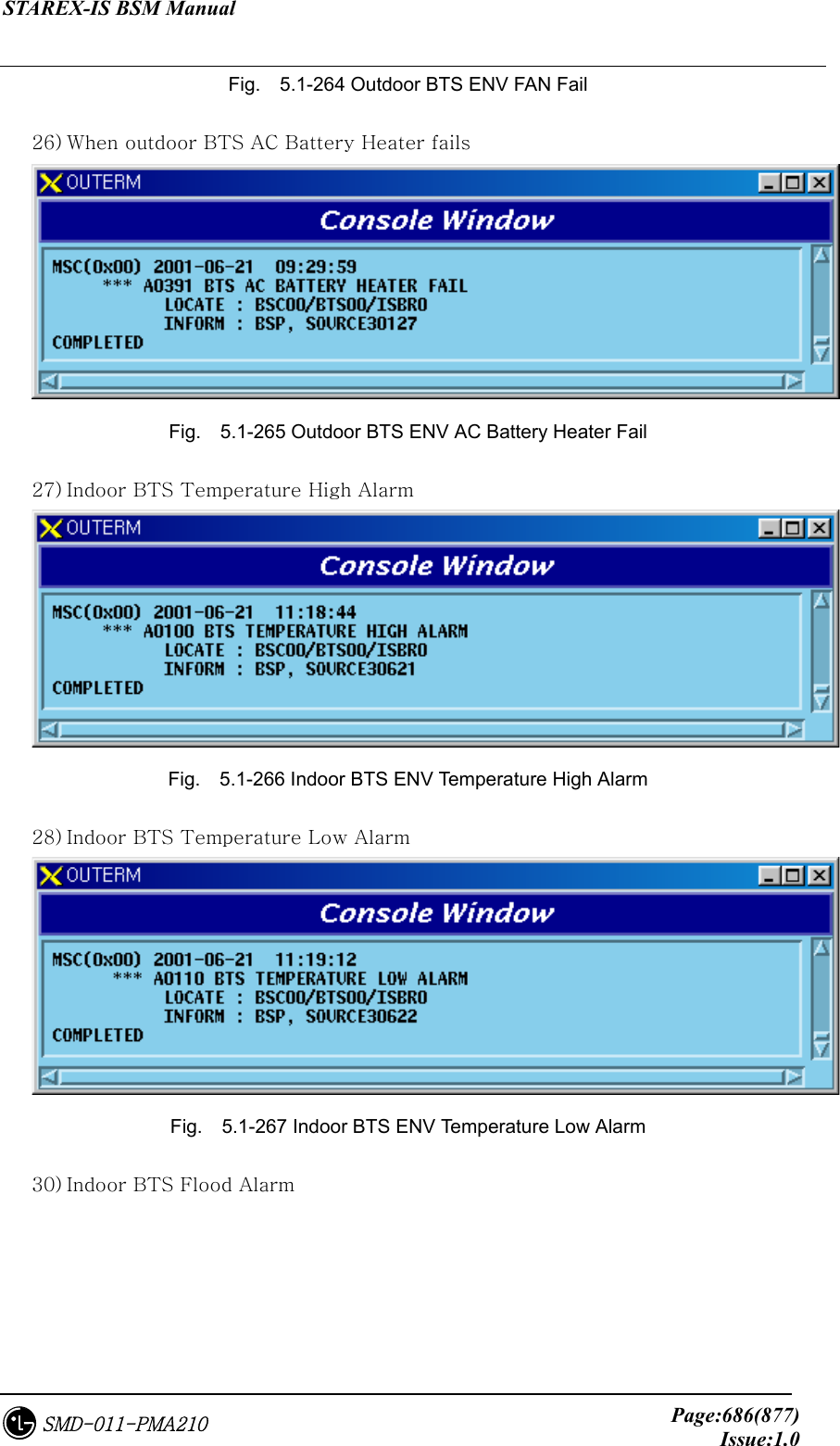
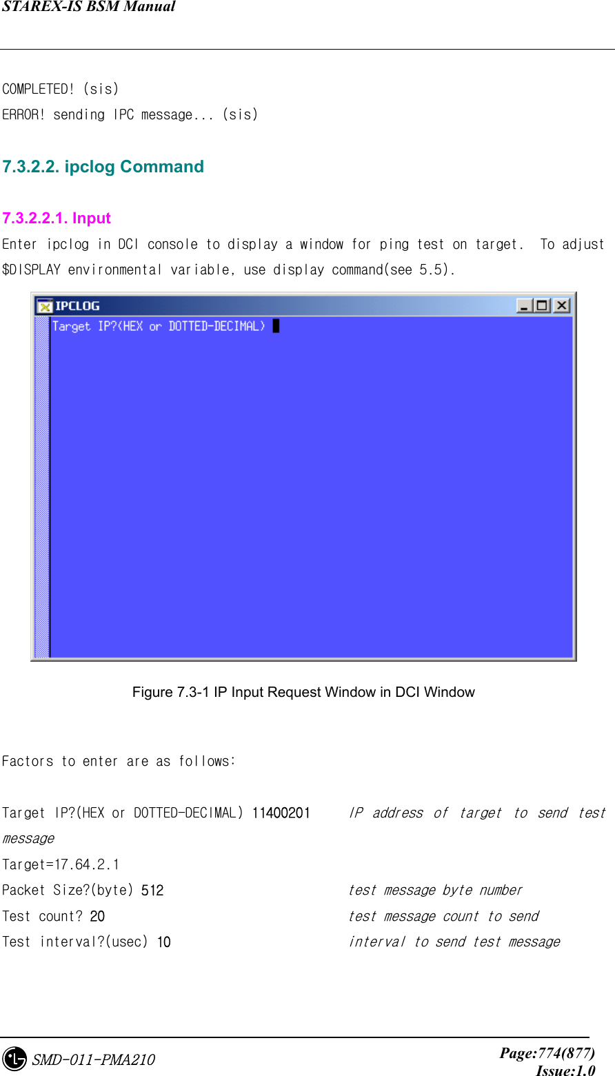
![STAREX-IS BSM Manual Page:773(877)Issue:1.0SMD-011-PMA210 7.3.2. Function to test Function This function includes sis and ipclog console command. sis command is to send IPC signal message for test to message queue, and ipclog command is to send test message to monitor the status of slave processor. 7.3.2.1. sis Command 7.3.2.1.1. Input If simply inputting sis, the following question is displayed: Message queue key? (HEX) 20B key value of message queue to store message Message type? (DECIMAL) 1920 message type: Sets task ID(or process ID) of processor to receive message. Source IP address? (HEX or DOTTED-DECIMAL) 11400201 message header Src IP value Source Task ID? (DECIMAL) 82 message header Src TID value Destination IP address? (HEX or DOTTED-DECIMAL) 1DC00001 message header Dest IP value Destination Task ID? (DECIMAL) 1920 message header Dest TID value Signal ID? (HEX) A30 message header signal ID value Body Length? (DECIMAL) 8 test message body length Body Message? (8 HEX's) 01 23 45 67 89 AB CD EF test message body To avoid the above procedure, you can set the following factor: sis [Qkey Mtype SrcIP SrcTID DstIP DstTID SigID BodyLen Msg] To create test message the same as the above example, you can enter the following: sis 20B 1920 11400201 82 1DC00001 1920 A30 8 "01 23 45 67 89 AB CD EF” 7.3.2.1.2. Output Display of this command is to display the status of messsssage sending to message queue.](https://usermanual.wiki/LG-Electronics-USA/3G1XOUTBTS.Users-Manual-Part-5/User-Guide-178517-Page-173.png)
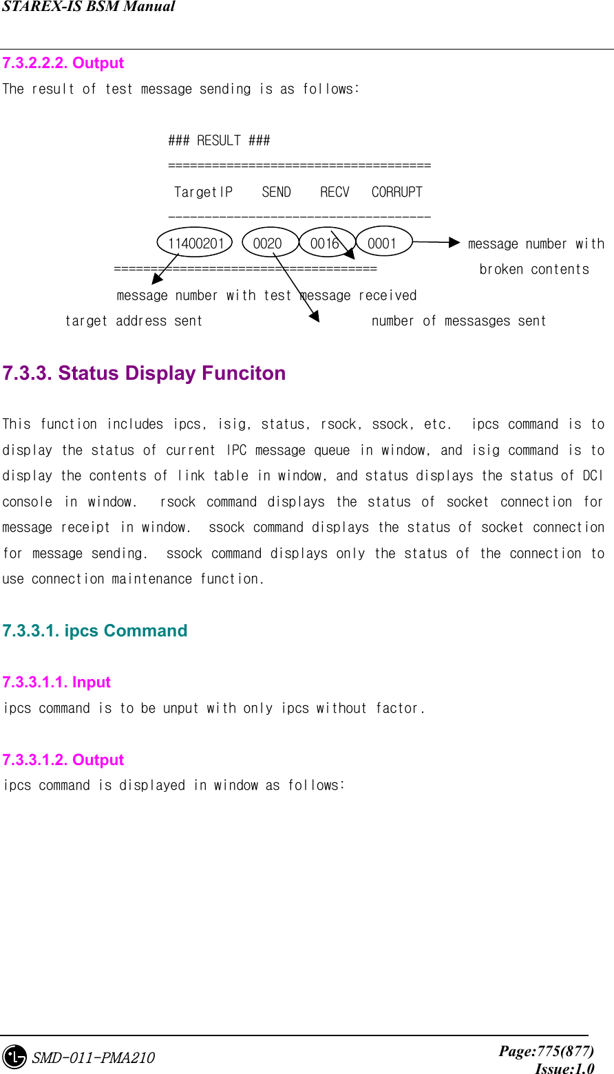
![STAREX-IS BSM Manual Page:777(877)Issue:1.0SMD-011-PMA210 queue key ### Initial Signal ID Information ### [#2561] SID(0x0A01) / QKey(0x020D) / PID(00779) signal ID [#2562] SID(0x0A02) / QKey(0x020D) / PID(00779) application to receive corresponding signal [#2563] SID(0x0A03) / QKey(0x020D) / PID(00779) [#2573] SID(0x0A0D) / QKey(0x020D) / PID(00779) process id [#2656] SID(0x0A60) / QKey(0x0205) / PID(00787) … … … … [#2690] SID(0x0A82) / QKey(0x0207) / PID(00792) [#2691] SID(0x0A83) / QKey(0x0208) / PID(00798) [#2705] SID(0x0A91) / QKey(0x0209) / PID(00829) [#2707] SID(0x0A93) / QKey(0x0209) / PID(00829) 7.3.3.3. status command 7.3.3.3.1. Input Only status is input without factor. 7.3.3.3.2. Output Output type of status command is as follows: Debug flag log flag eprt flag For developer only status(see 5.2) status(see 5.3) ### DCI Console Status ### PRINTF flag [OFF] LOG flag [ON ] EPRT flag [ON ] ASF flag [ON ] ASF SIGID [ALL ] ASF DST.IP [ALL ] asf flag ARF flag [ON ] ARF SIGID [0A00] ARF SRC.IP [11400101] state(see 2.1) arf flag state(see 2.2) 7.3.3.4. rsock command](https://usermanual.wiki/LG-Electronics-USA/3G1XOUTBTS.Users-Manual-Part-5/User-Guide-178517-Page-177.png)
![STAREX-IS BSM Manual Page:778(877)Issue:1.0SMD-011-PMA210 7.3.3.4.1. input Withput factor, rsock should be input. 7.3.3.4.2. Output The output of rsock command is reported in the following format. ### RECEIVE SOCKET TABLE ### [0] FD[4] IP[11400201] READY[0] CREAT[02-26 12:06:11] [1] FD[6] IP[12400501] READY[1] CREAT[02-26 11:03:23] [2] FD[7] IP[11400101] READY[0] CREAT[02-26 11:22:13] … socket target receipt message connection creation time descriptor IP address waiting status 7.3.3.5. ssock command 7.3.3.5.1. Input Only ssock should be input withput factor. 7.3.3.5.2. Output The output of ssock command is reported in the following format: ### SEND SOCKET TABLE ### [0] FD[3] IP[11400201] CREAT[02-26 12:06:11] FINISH[02-26 12:06:28] [1] FD[4] IP[11400101] CREAT[02-26 12:06:15] FINISH[02-26 12:06:32] … socket target connection creation time connection end descriptor IP address time expected](https://usermanual.wiki/LG-Electronics-USA/3G1XOUTBTS.Users-Manual-Part-5/User-Guide-178517-Page-178.png)
![STAREX-IS BSM Manual Page:779(877)Issue:1.0SMD-011-PMA210 7.3.4. Other Supplementary Function ls command can display available command list in window. log command is used to switch on and off the function to store event generated from DCI console and DCI in log file, and eprt command is used to switch on and off the function to display error generated from DCI in window. History related command is used for convenience in the case of repeatedly executing the previous command in DCI console. display command can be used to change $DISPLAY environmental variable necessary for ipclog window display. 7.3.4.1. ls command ls command is used to display the list of commands acailable in current DCI console in window. 7.3.4.2. log command log command can adjust save of DCI related log file. The usage of log command can be done in the format of log [on/off], and the status of current log flag can be checked by status command. The location for log file save is $EXECPATH/DCI_LOGS/dci.logdd, and (dd being current date), log file is stored for one month from the record date. 7.3.4.3. eprt command eprt command can adjust the status of whether to display various error messages generated from DCI in window, and default is on state. The usage of eprt command can be done in the format of eprt [on/off], and the status of current eprt flag can be checked by status command. 7.3.4.4. history, !!, !n command By history command, you can check the list of commands that have been used for 10 times, and by !!, !n command, you can repeat the previous command. History related commands can be used as follows:](https://usermanual.wiki/LG-Electronics-USA/3G1XOUTBTS.Users-Manual-Part-5/User-Guide-178517-Page-179.png)
![STAREX-IS BSM Manual Page:780(877)Issue:1.0SMD-011-PMA210 DCI_CON>> history ### Command History ### 9 : 8 : ls 7 : asf a01 6 : arf a03 11400101 5 : arf off 4 : rsock 3 : ipclog 2 : isig 1 : status 0 : ls DCI_CON>> !2 isig ### Initial Signal ID Information ### [#2690] SID(0x0A82) / QKey(0x0207) / PID(00792) [#2691] SID(0x0A83) / QKey(0x0208) / PID(00798) … 7.3.4.5. display command By display command, you can change the address to display ipclog window. When using DCI console for remote host other than workstation that activates BSM, upon use of ipclog, you should use display command in advance to change the value of $DISPLAY environmental variable. Set IP address of the host for display in the form of display 150.150.62.71.](https://usermanual.wiki/LG-Electronics-USA/3G1XOUTBTS.Users-Manual-Part-5/User-Guide-178517-Page-180.png)
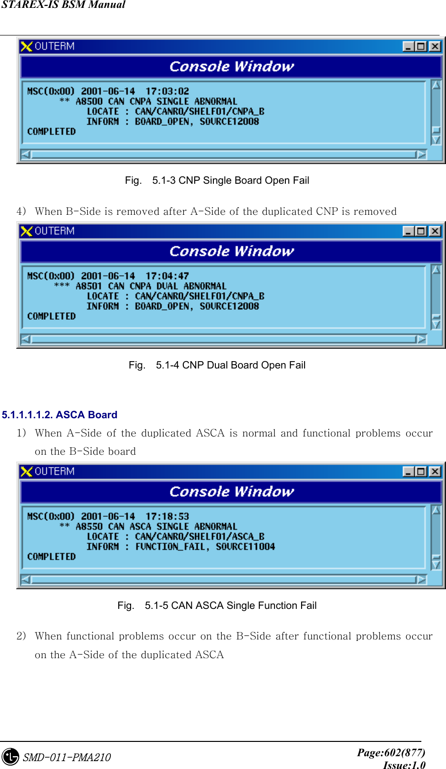
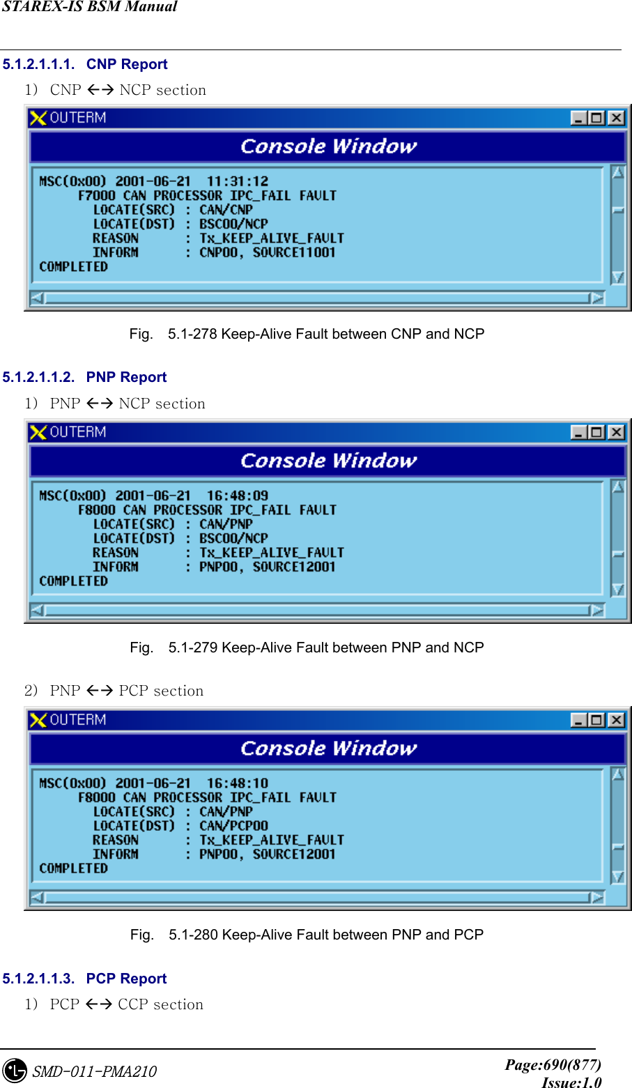
![STAREX-IS BSM Manual Page:793(877)Issue:1.0SMD-011-PMA210 7.5. PLD Data Structure 7.5.1. BSM layer 7.5.1.1. St_Bsm_Cfg.dg Table 7.5-1 St_Bsm_Cfg Data Type N a m e default Remarks byte ccp_id 0 ~ 12 byte bts_eqp[MAX_BTS] Current BTS equip ( 0: Not_equip 1 : Equip ) byte smp_eqp[MAX_SMP] Current SMP equip ( 0: Not_equip 1 : Equip ) byte vmp_eqp[MAX_VMP] byte msc_id 0 ~ 255 MSC Identification byte pcf_equ[MAX_PCF] 0 ~ 255 CAN PCF equip (0:Not_equip 1 : Equip) MAX_PCF : 3 ccp_id=0 is only valid. byte reserved_byte[35] 0 7.5.2. CNP ONLY 7.5.2.1. St_re_can_node.dg Table 7.5-2 t_re_can_node Type N a m e default Remarks byte card_id key full equip (MAX_ATM_CARD:5) byte link_id key full equip (MAX_ATM_LINK:32) byte equip Depending on the below Node Config, Equip Node status 1:Equip, 0:Not Equip byte link_type 1 ATM Link Type STM-1,STM-4,Cell Bus (LINK_TYPE_NONE(0),LINK_TYPE_STM1(1),LINK_TYPE_STM](https://usermanual.wiki/LG-Electronics-USA/3G1XOUTBTS.Users-Manual-Part-5/User-Guide-178517-Page-193.png)
![STAREX-IS BSM Manual Page:794(877)Issue:1.0SMD-011-PMA210 12(2), LINK_TYPE_STM14(3), LINK_TYPE_E1(4), LINK_TYPE_T1(5)) byte link_status 1 ATM Link Acktivity Init/Active/Block (LINK_STS_NONE(0), LINK_STS_ACTIVE(1), LINK_STS_ONL_BLOCK(2), LINK_STS_MMC_BLOCK(3)) byte connect_type Node Connection ID: End-User’s own ID (see Appendix Connection ID) byte fabric_no Switch Fabric No. (0: ASCA APC0,1: ASIA0 APC0,2: ASIA0 APC1, 3: ASIA1 APC0, 4: ASIA1 APC1, 5: ASIA2 APC0, 6: ASIA2 APC1, 7: ASIA3 APC0, 8: ASIA3 APC1) byte reserved[7] 7.5.2.2. St_re_can_addr.dg Table 7.5-3 St_re_can_addr Type N a m e Default Remarks byte shelf_id key full equip (MAX_CAN_SHELF: 4) byte slot_id key full equip (MAX_CAN_SLOT: 22) byte equip ‘0’ byte bd_type PBA’s own number (not yet set) byte no_sub Sub Processor Number in case of Sub processor had IP byte reserved word32 addr[MAX_SUB] MAX_SUB: 8 7.5.2.3. St_re_can_pvc.dg Table 7.5-4 St_re_can_pvc Type N a m e Default Remarks byte dummy key word16 no_entry # of Valid Entries, number of defined PVC information (~4096) word16 reserved](https://usermanual.wiki/LG-Electronics-USA/3G1XOUTBTS.Users-Manual-Part-5/User-Guide-178517-Page-194.png)
![STAREX-IS BSM Manual Page:795(877)Issue:1.0SMD-011-PMA210 byte equipage[4096] byte node_a[4096] Peer1 connection ID byte sub_a[4096] Peer1 Logical Info byte node_b[4096] Peer2 Connection ID byte sub_b[4096] Peer2 Logical info byte no_vc[4096] Number of VC to be used between Allocated VC Number Peers byte link_type[4096] Link Usage AAL1/2/5, Test (LINK_AAL2(0), LINK_AAL5(1), LINK_TEST(2)) word16 link_bw[4096] 0x100 VC Link Bandwidth (Cell Bandwidth(~0x40) to be assigned to Link) word32 vpci_a[4096] Peer1 VPI/VCI(Ingress VPCI) word32 vpci_b[4096] Peer2 VPI/VCI(Egress VPCI) 7.5.2.4. St_re_can_svc.dg Table 7.5-5 St_re_can_svc Type N a m e default Remarks byte dummy key word16 no_entry # of Valid Entries, defined PVC information number (~4096) byte no_hdr Header Address Length Upper ATM Address length byte reserved byte addr_hdr[20] Higher ATM address byte equipage[512] byte a_mask1[512][10] First address mask to be connected byte addr1[512][10] First address to be connected byte a_mask2[512][10] Second address mask to be connected byte addr2[512][10] Second address to be connected byte no_vc[512] Number of VC to be used between peers word32 atm_id1[512] vc id of the first node (VPI:VCI) word32 atm_id2[512] vc id of the second node (VPI:VCI) byte link_type[512] Link Usage(AAL1/2/5,Test)](https://usermanual.wiki/LG-Electronics-USA/3G1XOUTBTS.Users-Manual-Part-5/User-Guide-178517-Page-195.png)
![STAREX-IS BSM Manual Page:796(877)Issue:1.0SMD-011-PMA210 ( LINK_AAL2(0), LINK_AAL5(1), LINK_TEST(2)) word16 link_bw[512] VC Link BandWidth (Cell Bandwidth(~0x40) to be assigned to Link) 7.5.2.5. St_re_can_net_cfg.dg Table 7.5-6 St_re_can_net_cfg Type N a m e default Remarks byte can_net_shelf_id key full equip (MAX_CAN_NET_SHELF: 2) byte can_net_slot_id key full equip (MAX_CAN_SLOT: 22) byte equip ‘0’ byte bd_type Network Board Type byte no_sub # of Sub Device byte no_link # of Physical Link byte hw_ctrl HW Reset : 0(Init), 1, 2, 3 added byte link_type[MAX_LINK] 1 Physical Link Type : STM1, E1,...(MAX_LINK: 64) LINK_TYPE_NONE(0),LINK_TYPE_STM1(1),LINK_TYPE_STM12(2), LINK_TYPE_STM14(3), LINK_TYPE_E1(4), LINK_TYPE_T1(5) byte sub_type[MAX_SUB] Sub Device Type (MAX_SUB : 16) SBTYPE_NONE(0), SBTYPE_APC(1), SBTYPE_APPD(2) byte sub_id[MAX_SUB] Sub Device ID (MAX_SUB : 16) 7.5.2.6. St_re_can_net_data.dg Table 7.5-7 St_re_can_net_data Type N a m e default Remarks byte dummy key byte cn_id msc_no Core Network ID](https://usermanual.wiki/LG-Electronics-USA/3G1XOUTBTS.Users-Manual-Part-5/User-Guide-178517-Page-196.png)
![STAREX-IS BSM Manual Page:797(877)Issue:1.0SMD-011-PMA210 byte no_addr_hdr ATM Address Header Len byte reserved[2] byte rnc_equip[MAX_RNC] rnc_eqp RNC Equipage byte atm_addr_hdr[20] ATM Address Header byte rnc_conn_type[MAX_RNC] RNC Connectino ID byte atsa_conn_type[12] ATSA Connection ID word32 rnc_addr[MAX_RNC] RNC NCP Network Address word32 camu_addr[16] CAMU Device Network Addr. (0 : ASCA_A, 1 : ASCA_B, 2 : ASIA0_A, 3 : ASIA0_B, 4 : ASIA1_A, 5 : ASIA1_B 6 : ASIA2_A, 7 : ASIA2_B, 8 : ASIA3_A, 9 : ASIA3_B, 10 : AOTA0, 11 : AOTA1, 12 : AOTA2, 13 : AOTA3, 14 : ATSA0, 15 : ATSA1) byte reserved[8] 7.5.2.7. St_re_can_iur_con.dg Table 7.5-8 St_re_can_iur_con Type N a m e default Remarks byte rnc_id key full equip word32 start_aal2_vc_id[MAX_RNC] See *1 AAL2 Start VC Id word16 no_aal2_vc 32 Number of AAL2 VCs word16 reserved 7.5.2.8. St_re_can_rnc5_con.dg Table 7.5-9 St_re_can_rnc5_con Data Type N a m e default Remarks byte dummy key word32 start_aal5_vc_id[2] [10/32] = 0xA0020 [12/32] = 0xC0020 AAL5 Start VC Id word16 no_aal5_vc 8192 Number of AAL5 VCs word16 reserved](https://usermanual.wiki/LG-Electronics-USA/3G1XOUTBTS.Users-Manual-Part-5/User-Guide-178517-Page-197.png)
![STAREX-IS BSM Manual Page:798(877)Issue:1.0SMD-011-PMA210 7.5.3. PNP ONLY 7.5.3.1. St_re_cand_node.dg Table 7.5-10 St_re_cand_node Data Type N a m e default Remarks byte card_id key full equip (MAX_ATM_CARD:5) byte link_id key full equip (MAX_ATM_LINK:32) byte equip LINK_NOT_EQUIP(0), LINK_EQUIP(1) byte link_type 1 ATM Link Type STM-1,STM-4,Cell Bus (LINK_TYPE_NONE(0),LINK_TYPE_STM1(1), LINK_TYPE_STM12(2), LINK_TYPE_STM14(3), LINK_TYPE_E1(4), LINK_TYPE_T1(5)) byte link_status 1 ATM Link Acktivity Init/Active/Block (LINK_STS_NONE(0), LINK_STS_ACTIVE(1), LINK_STS_ONL_BLOCK(2), LINK_STS_MMC_BLOCK(3)) byte connect_type End-User’s own ID connected to Link (see Appendix Connection ID) byte fabric_no Switch Fabric No.( Index(0~8) of all APCs) (0:ASCA APC0, 1:ASIA0 APC0, 2:ASIA0 APC1, 3:ASIA1 APC0, 4:ASIA1 APC1, 5:ASIA2 APC0, 6: ASIA2 APC1, 7:ASIA3 APC0, 8 : ASIA3 APC1) byte reserved[7] 7.5.3.2. St_re_pcf_node.dg Table 7.5-11 St_re_pcf_node Type N a m e Default Remarks byte pcf_id key full equip (MAX_PCF_BLK:6)](https://usermanual.wiki/LG-Electronics-USA/3G1XOUTBTS.Users-Manual-Part-5/User-Guide-178517-Page-198.png)
![STAREX-IS BSM Manual Page:799(877)Issue:1.0SMD-011-PMA210 byte link_id key full equip (MAX_SUB_LINK:32) byte equip Number of pcf Equip as below LINK_NOT_EQUIP(0), LINK_EQUIP(1) byte link_type 1 ATM Link Type STM-1,STM-4,Cell Bus LINK_TYPE_NONE(0), LINK_TYPE_STM1(1), LINK_TYPE_STM12(2), LINK_TYPE_STM14(3), LINK_TYPE_E1(4), LINK_TYPE_T1(5) byte link_status 1 ATM Link Acktivity Init/Active/Block LINK_STS_NONE(0), LINK_STS_ACTIVE(1), LINK_STS_ONL_BLOCK(2), LINK_STS_MMC_BLOCK(3) byte connect_type Default 1 below. Node Connection ID: End-User’s own ID connected to Link byte fabric_no 0 Switch Fabric No. Index(0~8) of all APCs 0 : BCRA APC0 byte reserved[7] 7.5.3.3. St_re_cand_addr.dg Table 7.5-12 St_re_cand_addr Type N a m e Default Remarks byte shelf_id key full equip (MAX_CAN_SHELF: 4) byte slot_id key full equip (MAX_CAN_SLOT: 22) byte equip ‘0’ byte bd_type Processor/Device Board Type PBA’s own number (not yet set) byte no_sub Sub Processor Number In case of Sub processor had IP Nu,ber of processors mounted byte reserved word32 addr[MAX_SUB] MAX_SUB: 8](https://usermanual.wiki/LG-Electronics-USA/3G1XOUTBTS.Users-Manual-Part-5/User-Guide-178517-Page-199.png)
![STAREX-IS BSM Manual Page:800(877)Issue:1.0SMD-011-PMA210 7.5.3.4. St_re_cand_pvc.dg Table 7.5-13 St_re_cand_pvc Type N a m e default Remarks byte dummy key word16 no_entry # of Valid Entries, number of defined PVC information (~4096) word16 reserved byte equipage[4096] cand_pvc.inf byte node_a[4096] Peer1 connection ID byte sub_a[4096] Peer1 Logical Info byte node_b[4096] Peer2 Connection ID byte sub_b[4096] Peer2 Logical info byte no_vc[4096] Number of VX to be used between Allocated VC Number Peers byte link_type[4096] Link Usage AAL1/2/5, Test (LINK_AAL2(0), LINK_AAL5(1), LINK_TEST(2)) word16 link_bw[4096] 0x100 VC Link Bandwidth (Cell Bandwidth(~0x40) to be assigned to Link) word32 vpci_a[4096] Peer1 VPI/VCI(Ingress VPCI) word32 vpci_b[4096] Peer2 VPI/VCI(Egress VPCI) 7.5.3.5. St_re_pcf_pvc.dg Table 7.5-14 St_re_pcf_pvc Type N a m e Default Remarks byte dummy key word16 no_entry # of Valid Entries, number of defined PVC information (~4096) word16 reserved byte equipage[512] pcf_pvc.inf byte node_a[512] Peer1 connection ID byte sub_a[512] Peer1 Logical Info](https://usermanual.wiki/LG-Electronics-USA/3G1XOUTBTS.Users-Manual-Part-5/User-Guide-178517-Page-200.png)
![STAREX-IS BSM Manual Page:801(877)Issue:1.0SMD-011-PMA210 byte node_b[512] Peer2 Connection ID byte sub_b[512] Peer2 Logical info byte no_vc[512] Number of VCs to be used between Allocated VC Number Peers byte link_type[512] Link Usage AAL1/2/5, Test LINK_AAL2(0), LINK_AAL5(1), LINK_TEST(2) word16 link_bw[512] 0x100 Cell Bandwidth(~0x40) to be assigned to VC Link Bandwidth-Link word32 vpci_a[512] Peer1 VPI/VCI(Ingress VPCI) word32 vpci_b[512] Peer2 VPI/VCI(Egress VPCI) 7.5.3.6. St_re_cand_svc.dg Table 7.5-15 St_re_cand_svc Type N a m e default Remarks byte dummy key word16 no_entry # of Valid Entries, number of defined PVC info (~4096) byte no_hdr Header Address Length Upper ATM Address length byte reserved byte addr_hdr[20] Higher ATM address byte equipage[512] byte a_mask1[512][10] First address mask to be connected byte addr1[512][10] First address to be connected byte a_mask2[512][10] Second address mask to be connected byte addr2[512][10] Second address to be connected byte no_vc[512] Number of VCs to be used between peers word32 atm_id1[512] vc id of first node (VPI:VCI) word32 atm_id2[512] vc id of second node (VPI:VCI) byte link_type[512] Link Usage(AAL1/2/5,Test) ( LINK_AAL2(0), LINK_AAL5(1), LINK_TEST(2)) word16 link_bw[512] VC Link BandWidth (Cell Bandwidth(~0x40) to be assigned to](https://usermanual.wiki/LG-Electronics-USA/3G1XOUTBTS.Users-Manual-Part-5/User-Guide-178517-Page-201.png)
![STAREX-IS BSM Manual Page:802(877)Issue:1.0SMD-011-PMA210 Link) 7.5.3.7. St_re_cand_net_cfg.dg Table 7.5-16 St_re_cand_net_cfg Type N a m e default Remarks byte can_net_shelf_id key full equip (MAX_CAN_NET_SHELF: 2) byte can_net_slot_id key full equip (MAX_CAN_SLOT: 22) byte equip ‘0’ byte bd_type Network Board Type byte no_sub # of Sub Device byte no_link # of Physical Link byte hw_ctrl HW Reset : 0(Init), 1, 2, 3 added byte link_type[MAX_LINK] 1 Physical Link Type : STM1, E1,...(MAX_LINK: 64) LINK_TYPE_NONE(0),LINK_TYPE_STM1(1),LINK_TYPE_STM12(2), LINK_TYPE_STM14(3), LINK_TYPE_E1(4), LINK_TYPE_T1(5) byte sub_type[MAX_SUB] Sub Device Type (MAX_SUB : 16) SBTYPE_NONE(0), SBTYPE_APC(1), SBTYPE_APPD(2) byte sub_id[MAX_SUB] Sub Device ID (MAX_SUB : 16) 7.5.3.8. St_re_cand_net_data.dg Table 7.5-17 St_re_cand_net_data Type N a m e default Remarks byte dummy key byte msc_id msc_no:0 MSC ID byte reserved byte pcf_equip[6] Number of pcf equip PCF Equipage byte rnc_equip[MAX_RNC] Number of RNC equipage Header](https://usermanual.wiki/LG-Electronics-USA/3G1XOUTBTS.Users-Manual-Part-5/User-Guide-178517-Page-202.png)
![STAREX-IS BSM Manual Page:803(877)Issue:1.0SMD-011-PMA210 rnc equip byte pcf_conn_type[6][2] PCF Connectino ID byte rnc_conn_type[MAX_RNC] RNC Connection ID word32 pcp_addr[6] word32 ncp_addr[MAX_RNC] RNC NCP Network Address word32 camdu_addr[16] CAMD Device Network Addr. (0 : ASCA_A, 1 : ASCA_B, 2 : ASIA0_A, 3 : ASIA0_B, 4 : ASIA1_A, 5 : ASIA1_B 6 : ASIA2_A, 7 : ASIA2_B, 8 : ASIA3_A, 9 : ASIA3_B, 10 : AOTA0, 11 : AOTA1, 12 : AOTA2, 13 : AOTA3, 14 : ATSA0, 15 : ATSA1) 7.5.3.9. St_re_cand_data5_con.dg Table 7.5-18 St_re_cand_data5_con Type N a m e Default Remarks byte dummy key word32 start_aal5_vc_id[MAX_RNC] [10/32] = 0xA0020 AAL5 Start VC Id. word16 no_aal5_vc 8192 # of AAL5 VCs word16 reserved 7.5.3.10. St_re_cand_pif5_con.dg Table 7.5-19 St_re_cand_pif5_con Type N a m e default Remakrs byte Dummy key word32 start_aal5_vc_id[11][2] AAL5 Start VC Id. (22 VPs) word16 no_aal5_vc 512 # of AAL5 VCs word16 Reserved](https://usermanual.wiki/LG-Electronics-USA/3G1XOUTBTS.Users-Manual-Part-5/User-Guide-178517-Page-203.png)
![STAREX-IS BSM Manual Page:804(877)Issue:1.0SMD-011-PMA210 7.5.4. PCP ONLY 7.5.4.1. St_pdsn_addr_data_type Table 7.5-20 St_pdsn_addr_data_type Type Name default Remarks byte dummy byte no_of_pdsn 1 Number of equipped PDSN. Of MAX_PDSN_NO, the number of correct PDSN should be checked. word32 pdsn_ip[MAX_PDSN_NO] PDSN IP MAX_PDSN_NO = 2 (temporal) IP used by PDSN for Public Networkinterface. Home Agent IP. As several PDSNs can be interfaced, extendibility is considered. If this value is “0”, regard each RPP IP as PDSN IP. byte no_of_pdsn_node[MAX_PDSN_NO] RPP number mounted in PDSN STP configurqation includes 16 RPPs in PDSN. It must include the number of correct RPP in PDSN. word32 pdsn_node_ip[MAX_PDSN_NO][MAX_NODE_NO] RPP IPs MAX_NODE_NO = 20 PDSN RPP IP. Insert IP of mounted RPP in order, and insert the rest with 0. byte ssk_value[MAX_PDSN_NO][MAX_NODE_NO][16] 0 ssk value of PDSN_NODE that interfaces with PCF. Should be set per PDSN_NODE. byte ssk_len[MAX_PDSN_NO][MAX_NODE_NO]; 0 ssk_val length ssk_value[] length As value required for data call, upon ssk_vale change, the length should be calculated. byte reserved[32] 0 7.5.4.2. St_PCF_timer_type Table 7.5-21 St_PCF_timer_type](https://usermanual.wiki/LG-Electronics-USA/3G1XOUTBTS.Users-Manual-Part-5/User-Guide-178517-Page-204.png)
![STAREX-IS BSM Manual Page:805(877)Issue:1.0SMD-011-PMA210 Type Name default Remarks byte dummy word16 Trp_lifetime 1800 PCF timer. Range : 0 ~ 65,535 unit : 60sec 0x0000 = Release 0xFFFF = Infinite word16 Tbsreq9 5000 PCF timer. Range : 0 ~ 5000 Unit : 1msec word16 Tdiscon9 5000 PCF timer. Range : 0 ~ 5000 unit : 1msec word16 Twaitho9 10000 PCF timer. Range : 0 ~ 10000 Unit : 1msec word16 Tregreq 5000 PCF timer. Range : 0 ~ 5000 Unit : 1msec word16 regreq_retry_cnt 2 Registration Request message retransfer count that PCF sends to PDSN. Range : 0 ~ 20 Unit : frequency. If no response from PDSN, a maximum of this value should be resent. byte reserved[32] 7.5.4.3. St_PCF_info_data_type Table 7.5-22 St_PCF_info_data_type TYPE Name default Remarks byte dummy byte identification_type 0 Upon A11 Signaling, identification field type is determined. 0 : Time Stamp](https://usermanual.wiki/LG-Electronics-USA/3G1XOUTBTS.Users-Manual-Part-5/User-Guide-178517-Page-205.png)
![STAREX-IS BSM Manual Page:806(877)Issue:1.0SMD-011-PMA210 1 : Nonce word32 pcp_ip[MAX_PCF_SHELF][MAX_PCP_NO] PCP IP, PMP IP MAX_PCF_SHELF = 2 MAX_PCP_NO = 2 PCP/PMP IP executing F/E interface. [0][0] : PCP (Active) [0][1] : PCP (Standby) [1][0] : PMP (Active) [1][1] : PMP (Standby) word32 pip_ip[MAX_PCF_SHELF][MAX_PIP_NO] PIP IPs MAX_PCF_SHELF = 2 MAX_PIP_NO = 11 PIP IP executing F/E interface. word32 net_mask[MAX_PCF_SHELF][MAX_PIP_NO] 0 To be judged. PLD add. word32 default_gw[MAX_PCF_SHELF][MAX_PIP_NO] 0 Default Gateway. To be determined. PLD added. byte aaa_server_type 0 AAA server type word16 sid System ID. word16 nid Network ID. Int32 ltm_off 18 Offset of local time from System time. Thatis, local time offset from UTC. Current local time = SYS_TIME - LP_SEC + ltm_off ltm_off = 18 ( 30 minutes per unit, that is, 9 hour difference) * LP_SEC : Number of Leap seconds that occurred since the start of System Time. boolean day_lt 0 Daylight saving time flag (Summer time) 1 : day lighting saving time 0 : standard time byte gre_seq_flag 0 1 : Used SEQ 0 : Not Used SEQ word16 seq_cntl_timer 0 Upon PCF Sequence Control, timer that waitsspecific seq_num ( buffering time ) unit ( msec )](https://usermanual.wiki/LG-Electronics-USA/3G1XOUTBTS.Users-Manual-Part-5/User-Guide-178517-Page-206.png)
![STAREX-IS BSM Manual Page:807(877)Issue:1.0SMD-011-PMA210 byte pkt_zone_id 0 byte UDR_MSID_TYPE 0 MSID Type in UDR that PDSN sends to AAA Server 1 : IMSI 0 : MIN byte reserved[32] 0 7.5.4.4. St_pifu_HW_Reset_data_type Table 7.5-23 St_pifu_HW_Reset_data_type Type Name default Remarks byte shelf_id 0~1 key byte pcp_isolation[11] 0 0: not isolation 1:isolation byte bcra_isolation[2] 0 0: not isolation 1:isolation byte fera_isolation[2] 0,1 0: not isolation.................................................byte feta_isolation 0 0: not isolation 1:isolation byte reserved[32] 0 7.5.5. CCP ONLY 7.5.5.1. St_fwdpwr_data_type.dg Table 7.5-24 St_fwdpwr_data_type Type N a m e default Remarks byte bts_id full full equip byte fer_id 0 ~ 1 Always Full equip word16 slow_down_time 1600 (msec) Gain down time. Applied during slow down mode. (0 ~ 20000) word16 fast_down_time 1600 (msec) Gain down time. Applied during fast down mode. (0 ~ 20000) byte steps_till_fast 0 Number of slow down before switching to fast down mode. (0 ~ 100) byte slow_down_delta 1 Gain down delta. Applied during slow down](https://usermanual.wiki/LG-Electronics-USA/3G1XOUTBTS.Users-Manual-Part-5/User-Guide-178517-Page-207.png)
![STAREX-IS BSM Manual Page:808(877)Issue:1.0SMD-011-PMA210 mode. (0 ~ 100) byte fast_down_delta 1 Gain down delta. Applied during gast down mode. (0 ~ 100) byte nominal_gain 50 Nominal tx gain of primary/secondary traffic. (0 ~ 127) byte max_tx_gain 80 Max.tx gain of primary/secondary traffic byte min_tx_gain 40 Min.tx gain of primary/secondary traffic. byte fer_threshold 6 % Frame Error Rate threshold determines the gain increase amount.(0 ~ 20) byte big_up_delta 10 Gain increase delta. Applied when the forward frame error rate contained in a PMRM exceeds ‘fer_threshold’.(0 ~ 100) byte small_up_delta 5 Gain increase delta. Applied when the forward frame error rate contained in a PMRM is less than ‘fer_threshold’(0 ~ 100) byte signal_delta_gain 96 Gain scaling factor of signaling traffic. ( 0 ~ 200 ) byte pcsc_delta_gain1 64 Gain scaling factor of PCSC bit.(1-cell) byte pcsc_delta_gain2 96 Gain scaling factor of PCSC bit.(2-cell) byte pcsc_delta_gain3 112 Gain scaling factor of PCSC bit.(3-cell) byte reserved_byte[33] 0 7.5.5.2. St_13_fwdpwr_data_type.dg Table 7.5-25 St_13_fwdpwr_data_type Type N a m e default Remarks byte bts_id full Full equip byte fer_id 0 ~ 1 Always Full equip word16 init_down_time 1000 Initial gain down time.(0 ~ 20000) word16 max_down_time 4000 Maximum gain down time.(0 ~ 20000) word16 min_down_time 200 Minimum gain down time.(0 ~ 20000) word16 time_down_delta 200 Gain down time down delta. Applied in good run state.(0 ~ 20000) word16 time_up_delta 400 Gain down time up delta. Applied in erasure run state.(0 ~ 20000)](https://usermanual.wiki/LG-Electronics-USA/3G1XOUTBTS.Users-Manual-Part-5/User-Guide-178517-Page-208.png)
![STAREX-IS BSM Manual Page:809(877)Issue:1.0SMD-011-PMA210 word16 state_chg_thresh 250 Number of consecutive good frames brings about good run state.(0 ~ 10000) word16 erase_meas_frames 250 Cumulative erasure measuring period.(0 ~ 65535) byte cont_erase_eftv 2 Number of consecutive erasures brings about tx gain increase. If 0, burst erasures have no effect.(0 ~ 127) byte cumul_erase_eftv 4 Number of cumulative erasures brings about tx gain increase. If 0, non-burst erasures have no effect.(0 ~ 127) byte nominal_gain 50 Nominal tx gain of primary/secondary traffic.(0 ~ 127) byte max_tx_gain 100 Max.tx gain of primary/secondary traffic. (0 ~ 127) byte min_tx_gain 40 Min.tx gain of primary/secondary traffic. (0 ~ 127) byte gain_down_delta 1 Gain decrease delta (0 ~ 127) byte big_up_delta 10 Gain increase delta. Applied when a gain-up condition is encountered during ERASURE-STATE. (0 ~ 100) byte small_up_delta 5 Gain increase delta. Applied when a gain-up condition is encountered during GOOD-STATE. (0 ~ 100) byte signal_delta_gain 96 Gain scaling factor of signaling traffic. (0 ~ 200) byte pcsc_delta_gain1 64 Gain scaling factor of PCSC bit.(1-cell) (0 ~ 200) byte pcsc_delta_gain2 96 Gain scaling factor of PCSC bit.(2-cell) (0 ~ 200) byte pcsc_delta_gain3 112 Gain scaling factor of PCSC bit.(3-cell) (0 ~ 200) byte reserved_byte[32] 0 7.5.5.3. St_revpwr_data_type.dg Table 7.5-26 St_revpwr_data_type](https://usermanual.wiki/LG-Electronics-USA/3G1XOUTBTS.Users-Manual-Part-5/User-Guide-178517-Page-209.png)
![STAREX-IS BSM Manual Page:810(877)Issue:1.0SMD-011-PMA210 Type N a m e default Remarks byte bts_id full byte fer_id 0 ~ 1 Always Full equip word16 pnom (pwrctl_nominal) 19416 initial Eb/No(dB) word16 pmax (pwrctl_max ) 23408 Maximum Eb/No(dB) word16 pmin (pwrctl_min)) 8288 Minimum Eb/No(dB) word16 pupf (pwrctl_up_full) 3072 Up for erase in full mode(dB) short pfrr (pwrctl_full_run_reset) -2 Fulls until full mode(count value) word16 pupe (pwrctl_up_erasure) 248 Up for erase in erase run(dB) word16 pupel(pwrctl_up_erasure_little) 50 Up for erase(dB) word16 pd (pwrctl_down) 48 Down for full(dB) word16 pvd (pwrctl_var_down) 4 Down for variable(dB) word16 pfw (pwrctl_full_wait) 2 Pause between up fulls(count value) short perl (pwrctl_erasure_run_lim) 5 Erase until erase run(count value) byte reserved_byte[32] 0 7.5.5.4. St_13_revpwr_data_type Table 7.5-27 St_13_revpwr_data_type Remarks Type N a m e default (As of 2000-3-6, on;y 1% used) fer_id : 0 byte bts_id full byte fer_id 0 ~ 1 Always Full equip word16 pnom (pwrctl_nominal) 19416 Initial pwrctl threshold value. (up to 109048 at word32) word16 pmax (pwrctl_max) 34304 Maximum pwrctl threshold value. (up to 109048 at word32) word16 pmin (pwrctl_min) 8288 Minimum pwrctl threshold value. (up to 109048 at word32) word16 rpc_big_up_delta 4608 Pwrctl threshold up delta. Applied when a pwrctl-threshold-up condition is encountered during ERASURE-STATE.](https://usermanual.wiki/LG-Electronics-USA/3G1XOUTBTS.Users-Manual-Part-5/User-Guide-178517-Page-210.png)
![STAREX-IS BSM Manual Page:811(877)Issue:1.0SMD-011-PMA210 word16 rpc_small_up_delta 2304 Pwrctl threshold up delta. Applied when a pwrctl-threshold-up condition is encountered during GOOD-STATE. byte rpc_non_erase_wait 2 Non-erasure rate waiting frame count after increasing pwrctl threshold. During the period, erasure rate frame has no effect. byte rpc_max_down_delta 48 Maximum pwrctl threshold down delta. byte rpc_min_down-delta 2 Minimum pwrctl threshold down delta. byte rpc_down_delta_inc_step 1 Increment step size of pwrctl threshold down delta up. byte rpc_cont_erase_eftv 2 Number of consecutive erasures brings about pwrctl-threshold-up. If 0, burst erasures have no effect. byte rpc_cumul_erase_eftv 3 Number of cumulative erasures during rpc_erase_meas_frames brings about pwrctl-threshold-up. If 0, non-burst erasures have no effect. word16 rpc_erase_meas_frames 450 Cumulative erasure measuring period. word16 rpc_state_chg_thresh 250 Number of consecutive good frames brings about GOOD-STATE. byte reserved_byte[34] 0 7.5.5.5. St_SlpSts_data_type Table 7.5-28 St_SlpSts_data_type Type N a m e Default Remarks BYTE SMP_ID full 0 ~ 4 SMP IDENTIFICATION BYTE SLP_ID full 0 ~ 17 SLP IDENTIFICATION BYTE SLP_STS 0 0: UNBLOCK 8: BLOCK BYTE SLAVE_STS[4] 0 0: UNBLOCK 8: BLOCK byte Rserved_byte[33] 0 7.5.5.6. St_VcpSts_data_type Table 7.5-29 St_VcpSts_data_type](https://usermanual.wiki/LG-Electronics-USA/3G1XOUTBTS.Users-Manual-Part-5/User-Guide-178517-Page-211.png)
![STAREX-IS BSM Manual Page:812(877)Issue:1.0SMD-011-PMA210 Type N a m e default Remarks BYTE VMP_ID full 0 ~ 7 VMP IDENTIFICATION BYTE VCP_ID full 0 ~ 15 VCP IDENTIFICATION BYTE SHELF_TYPE 0 0: PHASE1 1: PHASE2 BYTE VCP_STS 0 0: UNBLOCK 8: BLOCK BYTE VCP_SLAVE_STS[2] 0 0: UNBLOCK 8: BLOCK BYTE VCE_STS[8] 0 0: UNBLOCK 8: BLOCK byte reserved_byte[34] 0 7.5.5.7. St_Trunk_data_type Table 7.5-30 St_Trunk_data_type Type N a m e default Remarks BYTE VMP_ID full 0 ~ 7 VMP IDENTIFICATION BYTE VLIA_ID full 0 ~ 1 VLIA IDENTIFICATION BYTE VLIA_STS 0 0: UNBLOCK 8: BLOCK BYTE LINK_STS[16] 0 0: UNBLOCK 8: BLOCK byte ts_sts[16][32] 0 0: UNBLOCK 8: BLOCK byte ts_type[16][32] 0: Vocoder 1: NO7(ts being 16) byte reserved_byte[33] 0 7.5.5.8. St_T1_Trunk_data_type Table 7.5-31 St_T1_Trunk_data_type Type N a m e default Remarks byte btia_id 0 ~ 15 BTIA board identification (board to connect T1 link) byte T1_id 0 ~ 4 T1 link identification ( one BTIA holds 5 T1 links.) byte ts_id 0 ~ 23 Time slot identification ( 1 T1 link holds 24 Time slots.) byte type 0 ~ 1 0: used for vocoder assignment 1: current time slot is connected to STF(Signaling Terminal Function) for No.7](https://usermanual.wiki/LG-Electronics-USA/3G1XOUTBTS.Users-Manual-Part-5/User-Guide-178517-Page-212.png)
![STAREX-IS BSM Manual Page:813(877)Issue:1.0SMD-011-PMA210 byte sbp_no 0 ~ 14 sbp number of vocoder channel that is matched to each time slot byte svc_no 0 ~ 15 svc number of vocoder channel matched to each time slot byte vce_no 0 ~ 7 vocoder channel number matched to each time slot word cic Number matched to all time slots, that is, each time slot’s own number. byte dummy byte reserved_byte[34] 0 7.5.5.9. St_Bsc_data_type Table 7.5-32 St_Bsc_data_type Type N a m e default Remarks byte dummy_key byte bsc_id 0 ~ 11 bsc identification byte trunk_type 0 : E1 (LGT) 1 : T1 (NW) word16 inactive_timer 30 MS inactive status judgement level word16 dormant_timer 10 MS dormant status judgement level byte bad_frame_time byte pkt_zone Current default: 0 byte pcp_id Current default: 0 connected PCP ID byte band_class 0(DCN) 1(1900Mgz) 4(1800Mhz) band class of candidate frequency 800Mhz: 0 1800Mhz : 4 = domestic 1900Mhz: 1 = overseas byte reserved_byte[31] 0 7.5.5.10. St_target_fer_service_type Table 7.5-33 St_target_fer_service_type](https://usermanual.wiki/LG-Electronics-USA/3G1XOUTBTS.Users-Manual-Part-5/User-Guide-178517-Page-213.png)
![STAREX-IS BSM Manual Page:815(877)Issue:1.0SMD-011-PMA210 byte wll_offhook 1 byte rs1_markov 1 rate set 1 Markov Call byte rs2_markov 1 rate set 2 Markov Call byte fch_fer 1 RC3 data service (0~31) byte sch_fer 1 RC3 data service (0~31) byte dcch_fer 1 RC3 data service (0~31) byte Sch_loopback 0 byte Sch_loopback2 0 byte Reserved_byte[31] 0 7.5.5.11. St_MAHHO_data_type Table 7.5-34 St_MAHHO_data_type Type N a m e default Remarks byte bts_id full byte sector_id full byte border_flag 0: Off, 1: On byte band_class 0(DCN) 1(1900Mgz) 4(1800Mhz) band class of candidate frequency 800Mhz: 0 1800Mhz : 4 = domestic 1900Mhz: 1 = overseas byte Num_cdma_freq Number of candidate frequency word16 cdma_freq[MAX_CDMA_CH] Candidate frequency (cdmach_num) byte sf_total_ec_thresh 11111(bin) As threshold of total Ec value regarding Serving Frequency, this determines whether to search candidate frequency. byte sf_total_ec_io_thresh 26 As threshold of total Ec/Io value regarding Serving Frequency, this determines whether to search candidate frequency.](https://usermanual.wiki/LG-Electronics-USA/3G1XOUTBTS.Users-Manual-Part-5/User-Guide-178517-Page-215.png)
![STAREX-IS BSM Manual Page:816(877)Issue:1.0SMD-011-PMA210 If total Ec/Io value is lower than total threshold regarding serving frequency, it does not search the pilot of Candidate Frequency. byte diff_rx_pwr_thresh 0 As power difference threshold between received serving frequency and candidate frequency, this determines whether to search candidate frequency. byte min_total_pilot_ec_io 0 Ec/Io threshold of active set of candidate frequency byte cf_t_add 26 Threshod to add pilot to acticve set of candidate frequency. If of pilots that belondg to neighbor set of Candidate Frequency, there is a pilot that has better Ec/Io than cf_t_add, it is reported to BS through Candidate Frequency Search Report. byte tf_wait_time 30 After transition to target frequency, waiting time to receive good frame( 80ms unit) 30 2.4 second byte cf_srch_win_n 9 Basic Search Window for candidate frequency neighbor set ( it uses teg same value as that of search window to existing system parameter message) byte cf_srch_win_r 10 Basic search window for candidate frequency Remaining Set byte reserved_byte[35] 0 7.5.5.12. St_location_para_type Table 7.5-35 St_location_para_type](https://usermanual.wiki/LG-Electronics-USA/3G1XOUTBTS.Users-Manual-Part-5/User-Guide-178517-Page-216.png)
![STAREX-IS BSM Manual Page:817(877)Issue:1.0SMD-011-PMA210 Type N a m e default Remarks byte bts_id full byte sector_id full byte action_time_frame After set Action time, frame unit duration until first PUF probe. Before PUF pulse transfer, duration sent with nominal power byte puf_setup_size power control group unit. byte puf_pulse_size Duration that MS sends PUF pulse. Power control group unit. word16 puf_interval Interval between PUF Probes. frame unit byte puf_init_pwr Initial PUF Probe power. in units of dB byte puf_pwr_step PUF pulse power increase. in units of dB byte total_puf_probes Total PUF prove number byte max_pwr_puf Max. PUF Probe number that can be transmitted with max. Tx power byte reserved_byte[33] 0 7.5.5.13. St_pwr_cntl_para_type Table 7.5-36 St_pwr_cntl_para_type Type N a m e default Remarks byte bts_id full byte fer_id 0 ~ 30 byte pwr_cntl_step step size of forward link closed loop power control byte fpc_mode 0 operation mode of forward link closed loop power control It should be the same as fpc_punc_mode of St_Chip_pwr_cntl_para_data. byte fpc_fch_init_setpt initial Value of Forward Fundamental Channel Outer Loop Eb/Nt setpoint (hereinafter](https://usermanual.wiki/LG-Electronics-USA/3G1XOUTBTS.Users-Manual-Part-5/User-Guide-178517-Page-217.png)
![STAREX-IS BSM Manual Page:818(877)Issue:1.0SMD-011-PMA210 FFCOLS). 0.125dB unit byte fpc_fch_min_setpt Minimum value of FFCOLS. 0.125dB unit byte fpc_fch_max_setpt FFCOLS’s Maximum value. 0.125dB unit byte fpc_dcch_init_setpt Forward Dedicated Control Channel Outer Loop Eb/Nt setpoint (hereinafter FDCCOLS) initial value. 0.125dB byte fpc_dcch_min_setpt FDCCOLS’s Minimum value. 0.125dB byte fpc_dcch_max_setpt FDCCOLS’s Maximum value. 0.125dB byte fpc_sch_init_setpt Forward Supplemental Channel Outer Loop Eb/Nt setpoint(FSCOLS) initial value. 0.125dB byte fpc_sch_min_setpt FSCOLS’s Minimum value. 0.125dB byte fpc_sch_max_setpt FSCOLS’s Maximum value. 0.125dB byte fpc_setpt_thresh Forward link Power control Setpoint Threshold Value. 0.125dB byte fpc_setpt_thresh_sch Forward Supplemental Channel Power control Setpoint Threshold Value. 0.125dB byte fch_chan_adj_gain Channel Gain adjustment value for Reverse Fundamental Channel. Complement of 2 in 0.125dB unit. byte dcch_chan_adj_gain Channel Gain adjustment value for Reverse Dedicated Control Channel. Complement of 2 in 0.125dB unit. byte sch0_chan_adj_gain Channel Gain adjustment value for Reverse Supplemental Channel 0. Complement of 2 in 0.125dB unit. byte sch1_chan_adj_gain Channel Gain adjustment value for Reverse Supplemental Channel 1. Complement of 2 in 0.125dB unit. byte rl_att_adj_gain_1500[2] index 0: not using Reverse Pilot index 1: using Reverse Pilot 20ms frame, 1500bps Reverse Link](https://usermanual.wiki/LG-Electronics-USA/3G1XOUTBTS.Users-Manual-Part-5/User-Guide-178517-Page-218.png)
![STAREX-IS BSM Manual Page:819(877)Issue:1.0SMD-011-PMA210 Attribute Adjustment gain value. byte rl_att_adj_gain_2700[2] 20ms frame, 2700bps Reverse Link Attribute Adjustment gain value. byte rl_att_adj_gain_4800[2] 20ms frame, 4800bps Reverse Link Attribute Adjustment gain value. byte rl_att_adj_gain_9600[2] 20ms frame, 9600bps Reverse Link Attribute Adjustment gain value. byte rl_att_adj_gain_1800[2] 20ms frame, 1800bps Reverse Link Attribute Adjustment gain value. byte rl_att_adj_gain_3600[2] 20ms frame, 3600bps Reverse Link Attribute Adjustment gain value. byte rl_att_adj_gain_7200[2] 20ms frame, 7200bps Reverse Link Attribute Adjustment gain value. byte rl_att_adj_gain_14400[2] 20ms frame, 14400bps Reverse Link Attribute Adjustment gain value. byte norm_att_gain_9600_5ms[2] 5ms frame, 9600bps Reverse Link Attribute Adjustment gain value. byte rl_att_adj_gain_19200[2][2] 2nd index 0: 2dn index 1: Turbo Encoding 20ms frame, 19200bps Reverse Link Attribute Adjustment gain byte rl_att_adj_gain_38400[2][2] 20ms frame, 38400bps Reverse Link Attribute Adjustment gain byte rl_att_adj_gain_76800[2][2] 20ms frame, 76800bps Reverse Link Attribute Adjustment gain byte rl_att_adj_gain_153600[2][2] 20ms frame, 153600bps Reverse Link Attribute Adjustment gain byte rl_att_adj_gain_307200[2][2] 20ms frame, 307200bps Reverse Link Attribute Adjustment gain byte rl_att_adj_gain_614400[2][2] 20ms frame, 614400bps Reverse Link Attribute Adjustment gain byte rl_att_adj_gain_28800[2][2] 20ms frame, 28800bps Reverse Link Attribute Adjustment gain byte rl_att_adj_gain_576600[2][2] 20ms frame, 576600bps Reverse Link Attribute Adjustment gain byte rl_att_adj_gain_115200[2][2] 20ms frame, 115200bps Reverse Link](https://usermanual.wiki/LG-Electronics-USA/3G1XOUTBTS.Users-Manual-Part-5/User-Guide-178517-Page-219.png)
![STAREX-IS BSM Manual Page:820(877)Issue:1.0SMD-011-PMA210 Attribute Adjustment gain byte rl_att_adj_gain_230400[2][2] 20ms frame, 230400bps Reverse Link Attribute Adjustment gain byte rl_att_adj_gain_460800[2][2] 20ms frame, 460800bps Reverse Link Attribute Adjustment gain byte rl_att_adj_gain_1036800[2][2] 20ms frame, 1036800bps Reverse Link Attribute Adjustment gain byte fpc_subchan_gain byte rl_gain_adj byte rlgain_traffic_pilot byte rlgain_sch_pilot byte reserved_byte[33] 0 7.5.5.14. St_sch_param_data Table 7.5-37 St_sch_param_data Type N a m e default Remarks byte bts_id full byte sector_id full byte sch_t_add 22 Regarding MDR handoff, t_add that is only appied as to Supplemental Code Channel byte sch_t_drop 26 Regarding MDR handoff, t_drop that is only applied as to Supplemental Code Channel byte t_mulchan threshold offset of Nghbr Pilot strength. 0.5dB step from 0.5dB to 4.0dB byte begin_preamble Preamble Frame number sent at the beginning of Reverse Supplemental (Code) Channel transfer byte resume_preamble Preamble Frame number sent upon retransfer of Reverse Supplemental (Code) Channel byte ps_min_delta Parameter necessary when operating in such mode as MS sending Pilot Strength Measurement Mini Message(PSMMM) whenever](https://usermanual.wiki/LG-Electronics-USA/3G1XOUTBTS.Users-Manual-Part-5/User-Guide-178517-Page-220.png)
![STAREX-IS BSM Manual Page:821(877)Issue:1.0SMD-011-PMA210 Active Set order changes. As threshold necessary so that MS judges PSMMM transfer, this is necessary upon such mode as MS sending PSMMM whenever the order of active set changes. byte order_interval Interval to report the difference between two pilot strengths through PSMMM. in units of 20ms byte num_pilots Parameter necessary for MS to send PSMMM. Pilot number reported through PSMMM byte periodic_interval Interval that MS sends PSMMM. in units of 20ms byte ps_floor_high Based on threshold, high water mark value set as to lower bound. byte ps_floor_low Based on threshold, low water mark valueset as to lower bound byte ps_ceiling_high Based on threshold, high water mark value set as to upper bound byte ps_ceiling_low Based on threshold, low water mark value set as to upper bound. byte threshold_interval Based on threshold, PSMMM transfer interval. in units of 20ms byte t_slotted Parameter included in In Traffic System Parameters Message byte reserved_byte[35] 7.5.5.15. St_IOS_para_data Table 7.5-38 St_IOS_para_data Type N a m e default Remarks byte dummy key byte T1 55 (0~255) Facilities Management(sec) byte T2 60 (0~255) Facilities Management(sec) byte T4 60 (0~255) Facilities Management(sec)](https://usermanual.wiki/LG-Electronics-USA/3G1XOUTBTS.Users-Manual-Part-5/User-Guide-178517-Page-221.png)
![STAREX-IS BSM Manual Page:823(877)Issue:1.0SMD-011-PMA210 byte T790 10 (0~60) Handoff (sec) byte T3113 5 (0~99) Call Processing (sec) byte T3210 30 (0~99) Mobility Management (sec) byte T3220 10 (0~99) Mobility Management (sec) byte T3230 5 (0~99) Call Processing (sec) byte T3240 5 (0~99) Mobility Management (sec) byte T3260 30 (0~99) Mobility Management (sec) byte T3270 5 (0~99) Mobility Management (sec) byte T3271 15 (0~99) Mobility Management (sec) byte T3272 5 (0~99) Mobility Management (sec) byte T3280 15 (0~99) Call Processing (sec) byte TA8_Setup 4 (0~99) A8,A9 Interfaces (sec) word16 Tacm 500 (0~1000) A3,A7 Interfaces (msec) word16 Talc9 500 (0~1000) A8,A9 Interfaces (msec) word16 Tald9 500 (0~1000) A8,A9 Interfaces (msec) word16 Tbstact 600 (0~1000) A3,A7 Interfaces (msec) word16 Tbstcom 100 (0~1000) A3,A7 Interfaces (msec) word16 Tchanstat 500 (0~1000) A3,A7 Interfaces (msec) word16 Tconn3 500 (1~1000) A3,A7 Interfaces (msec) word16 Tdiscon3 500 (1~1000) A3,A7 Interfaces (msec) byte Tdrptgt 5 (1~10) A3,A7 Interfaces (sec) byte Ttgtrmv 5 (1~10) A3,A7 Interfaces (sec) word16 Thoreq 1000 (0~50) A3,A7 Interfaces (msec) byte Tpaca1 5 (0~99) Call Processing (sec) byte Tpaca2 5 (0~99) Call Processing (sec) word16 Tpcm 1000 (0~20) A3,A7 Interfaces (msec) byte Tphysical 1 (0~10) A3,A7 Interface (sec) word16 Trel9 1000 (0~50) A8,A9 Interface (msec) byte reserved_byte[35] 7.5.5.16. St_Vcbu_HW_Reset_data_type Table 7.5-39 St_Vcbu_HW_Reset_data_type Type N a m e default Remarks Byte VMP_ID 0 ~ 7 VMP IDENTIFICATION](https://usermanual.wiki/LG-Electronics-USA/3G1XOUTBTS.Users-Manual-Part-5/User-Guide-178517-Page-223.png)
![STAREX-IS BSM Manual Page:824(877)Issue:1.0SMD-011-PMA210 Byte EquipPage According to Equip status 0: Not Equip 1: Equip Byte VMP_Isolation 0 0: not_isolation 1: isolation Byte VCP_Isolation[16] 0 0: not_isolation 1: isolation Byte VLIA_Isolation[2] 0 0: not_isolation 1: isolation Byte reserved_byte[34] 0 7.5.5.17. St_Slbu_HW_Reset_data_type Table 7.5-40 St_Slbu_HW_Reset_data_type Type N a m e Default Remarks Byte SMP_ID 0 ~ 4 SMP IDENTIFICATION Byte EquipPage According to Equip status 0: Not Equip 1: Equip Byte SMP_Isolation 0 0: not_isolation 1: isolation Byte SLP_Isolation[20] 0 0: not_isolation 1: isolation Byte rserved_byte[33] 0 7.5.6. NCP ONLY 7.5.6.1. St_re_atm_node.dg Table 7.5-41 St_re_atm_node Type N a m e default Remarks byte card_id key full equip (MAX_ATM_CARD:5) byte link_id key full equip (MAX_ATM_LINK:32) byte equip As many as Node Config below Equip 1: Equip, 0:Not-Equip byte link_type 1 STM-1, STM-4, Cell Bus (LINK_TYPE_NONE(0),LINK_TYPE_STM1(1),LINK_TYPE_STM12(2), LINK_TYPE_STM14(3), LINK_TYPE_E1(4), LINK_TYPE_T1(5)) byte link_status 1 Link status LINK_STS_NONE(0), LINK_STS_ACTIVE(1),](https://usermanual.wiki/LG-Electronics-USA/3G1XOUTBTS.Users-Manual-Part-5/User-Guide-178517-Page-224.png)
![STAREX-IS BSM Manual Page:825(877)Issue:1.0SMD-011-PMA210 LINK_STS_ONL_BLOCK(2), LINK_STS_MMC_BLOCK(3) byte connect_type End-User’s own ID connected to Link(see Appendix Connection ID) byte fabric_no Fabric is a serial number of APC. Index(0~8) of total APCs 0 : ASCA APC0, 1 : ASIA0 APC0, 2 : ASIA0 APC1, 3 : ASIA1 APC0, 4 : ASIA1 APC1, 5 : ASIA2 APC0, 6 : ASIA2 APC1, 7 : ASIA3 APC0, 8 : ASIA3 APC1 byte reserved[7] 7.5.6.2. St_re_slb_node.dg Table 7.5-42 St_re_slb_node Type N a m e default Remarks byte smp_id key full equip MAX_SLB:5 byte link_id key full equip (MAX_SUB_LINK:32) byte equip smp number As many as Node Config below, Equip 1: Equip, 0:Not-Equip byte link_type 1 STM-1, STM-4, Cell Bus (LINK_TYPE_NONE(0),LINK_TYPE_STM1(1),LINK_TYPE_STM12(2), LINK_TYPE_STM14(3), LINK_TYPE_E1(4), LINK_TYPE_T1(5)) byte link_status 1 Link status LINK_STS_NONE(0), LINK_STS_ACTIVE(1), LINK_STS_ONL_BLOCK(2), LINK_STS_MMC_BLOCK(3) byte connect_type End-User’s own ID connected to Link (see Appendix Connection ID) byte fabric_no 0 Index(0~8) of total APCs 0 : SLMA APC0 byte reserved[7] 7.5.6.3. St_re_vcb_node.dg Table 7.5-43 St_re_vcb_node](https://usermanual.wiki/LG-Electronics-USA/3G1XOUTBTS.Users-Manual-Part-5/User-Guide-178517-Page-225.png)
![STAREX-IS BSM Manual Page:826(877)Issue:1.0SMD-011-PMA210 Type N a m e Default Remarks byte vmp_id Key full equip MAX_VCB:8 byte link_id key full equip (MAX_SUB_LINK:32) byte equip Vmp number As many as Node Config below, Equip 1: Equip, 0:Not-Equip byte link_type 1 STM-1, STM-4, Cell Bus (LINK_TYPE_NONE(0),LINK_TYPE_STM1(1),LINK_TYPE_STM12(2), LINK_TYPE_STM14(3), LINK_TYPE_E1(4), LINK_TYPE_T1(5)) byte link_status 1 Link status LINK_STS_NONE(0), LINK_STS_ACTIVE(1), LINK_STS_ONL_BLOCK(2), LINK_STS_MMC_BLOCK(3) byte connect_type End-User’s own ID connected to Link (see Appendix Connection ID) byte fabric_no 0 Index(0~8) of total APCs 0 : VCMA APC0 byte reserved[7] 7.5.6.4. St_re_alb_node.dg Table 7.5-44 St_re_alb_node Type N a m e default Remarks byte alma_id key full equip (MAX_ALMA:2) byte link_id key full equip (MAX_ALS_LINK:16) byte equip As many as Node Config below, Equip 1: Equip, 0:Not-Equip byte link_type 1 STM-1, STM-4, Cell Bus (LINK_TYPE_NONE(0),LINK_TYPE_STM1(1),LINK_TYPE_STM12(2), LINK_TYPE_STM14(3), LINK_TYPE_E1(4), LINK_TYPE_T1(5)) byte link_status 1 Link status LINK_STS_NONE(0), LINK_STS_ACTIVE(1), LINK_STS_ONL_BLOCK(2), LINK_STS_MMC_BLOCK(3)](https://usermanual.wiki/LG-Electronics-USA/3G1XOUTBTS.Users-Manual-Part-5/User-Guide-178517-Page-226.png)
![STAREX-IS BSM Manual Page:827(877)Issue:1.0SMD-011-PMA210 byte connect_type End-User’s own ID connected to Link (see Appendix Connection ID) byte fabric_no 0 Index(0~8) of total APCs 0 : ALMA APC0 byte reserved[7] 7.5.6.5. St_re_bs_atm_node.dg Table 7.5-45 St_re_bs_atm_node Type N a m e default Remarks byte Bs_id key full equip MAX_BS:48 byte link_id key full equip (MAX_SUB_LINK:32) byte equip bs number As many as Node Config below, Equip 1: Equip, 0:Not-Equip byte link_type 1 STM-1, STM-4, Cell Bus (LINK_TYPE_NONE(0),LINK_TYPE_STM1(1),LINK_TYPE_STM12(2), LINK_TYPE_STM14(3), LINK_TYPE_E1(4), LINK_TYPE_T1(5)) byte link_status 1 Init/Active/Block LINK_STS_NONE(0), LINK_STS_ACTIVE(1), LINK_STS_ONL_BLOCK(2), LINK_STS_MMC_BLOCK(3)) byte connect_type End-User’s own ID connected to Link (see Appendix Connection ID) byte Fabric_no 0 index(0~8) of total APCs 0 : BCRA APC0 byte reserved[7] 7.5.6.6. St_re_rnc_bs_trunk.dg Table 7.5-46 St_re_rnc_bs_trunk Data Type N a m e default Remarks byte alma_id key full equip MAX_ALMA: 2](https://usermanual.wiki/LG-Electronics-USA/3G1XOUTBTS.Users-Manual-Part-5/User-Guide-178517-Page-227.png)
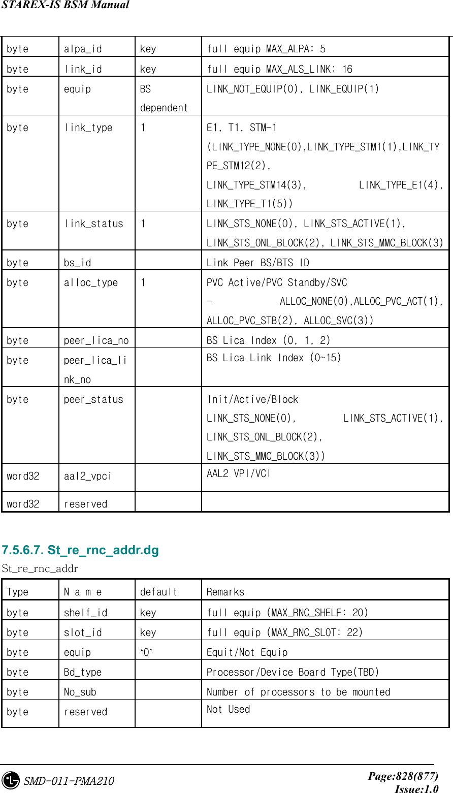
![STAREX-IS BSM Manual Page:829(877)Issue:1.0SMD-011-PMA210 word32 addr[8] Each Processor IP Address 7.5.6.8. St_re_bs_addr.dg St_re_bs_addr Type N a m e default Remarks byte bs_id key full equip MAX_BS: 48 byte shelf_id key full equip (MAX_BS_SHELF: 12) byte slot_id key full equip (MAX_BS_SLOT: 22) byte equip ‘0’ Equit/Not Equip byte bd_type Processor/Device Board Type(TBD) byte no_sub Number of processors mounted byte reserved Not Used word32 addr[8] Each Processor IP Address 7.5.6.9. St_re_atm_pvc.dg Table 7.5-47 St_re_atm_pvc Type N a m e default Remarks byte dummy key word16 no_entry # of Valid Entries, defined PVC information number (~4096) word16 reserved byte equipage[4096] Equip Flag byte node_a[4096] Peer1 connection ID (Ingress Node Conn. ID) byte sub_a[4096] Peer1 Logical Info byte node_b[4096] Peer2 Connection ID (Egress Node Conn. ID) byte sub_b[4096] Peer2 Logical info byte no_vc[4096] Number of VC to be used between Allocated VC Number Peers byte link_type[4096] Link LINK_AAL2(0), LINK_AAL5(1), LINK_TEST(2) word16 link_bw[4096] 0x100 VC Link Bandwidth](https://usermanual.wiki/LG-Electronics-USA/3G1XOUTBTS.Users-Manual-Part-5/User-Guide-178517-Page-229.png)
![STAREX-IS BSM Manual Page:830(877)Issue:1.0SMD-011-PMA210 (Cell Bandwidth(~0x40) to be assigned to Link) word32 vpci_a[4096] Peer1 VPI/VCI (Ingress VPCI) word32 vpci_b[4096] Peer2 VPI/VCI (Egress VPCI) 7.5.6.10. St_re_slb_pvc.dg Table 7.5-48 St_re_slb_pvc Type N a m e default Remarks byte dummy key word16 no_entry # of Valid Entries, defined PVC information number (~512) word16 reserved byte equipage[512] byte node_a[512] Peer1 connection ID (Ingress Node Conn. ID) byte sub_a[512] Peer1 Logical Info byte node_b[512] Peer2 Connection ID (Egress Node Conn. ID) byte sub_b[512] Peer2 Logical info byte no_vc[512] Number of VC to be used between Allocated VC Number Peers byte link_type[512] Link LINK_AAL2(0), LINK_AAL5(1), LINK_TEST(2) word16 link_bw[512] 0x100 VC Link Bandwidth (Cell Bandwidth(~0x40) to be assigned to Link) word32 vpci_a[512] Peer1 VPI/VCI (Ingress VPCI) word32 vpci_b[512] Peer2 VPI/VCI (Egress VPCI) 7.5.6.11. St_re_vcb_pvc.dg Table 7.5-49 St_re_vcb_pvc Type N a m e default Remarks byte dummy key word16 no_entry # of Valid Entries, defined PVC information number (~512)](https://usermanual.wiki/LG-Electronics-USA/3G1XOUTBTS.Users-Manual-Part-5/User-Guide-178517-Page-230.png)
![STAREX-IS BSM Manual Page:831(877)Issue:1.0SMD-011-PMA210 word16 reserved byte equipage[512] byte node_a[512] Peer1 connection ID (Ingress Node Conn. ID) byte sub_a[512] Peer1 Logical Info (measns final peer connection) byte node_b[512] Peer2 Connection ID (Egress Node Conn. ID) byte sub_b[512] Peer2 Logical info byte no_vc[512] Number of VC to be used between Allocated VC Number Peers byte link_type[512] Link LINK_AAL2(0), LINK_AAL5(1), LINK_TEST(2) word16 link_bw[512] 0x100 VC Link Bandwidth (Cell Bandwidth(~0x40) to be assigned to Link) word32 vpci_a[512] Peer1 VPI/VCI (Ingress VPCI) word32 vpci_b[512] Peer2 VPI/VCI (Egress VPCI) 7.5.6.12. St_re_alb_pvc.dg Table 7.5-50 St_re_alb_pvc Type N a m e default Remarks byte dummy key word16 no_entry # of Valid Entries, defined PVC information number (~512) word16 reserved byte equipage[512] byte Node_a[512] Peer1 connection ID (Ingress Node Conn. ID) byte sub_a[512] Peer1 Logical Info byte Node_b[512] Peer2 Connection ID (Egress Node Conn. ID) byte sub_b[512] Peer2 Logical info byte no_vc[512] Number of VC to be ysed between Allocated VC Number Peers byte Link_type[512] Link LINK_AAL2(0), LINK_AAL5(1), LINK_TEST(2) word16 Link_bw[512] 0x100 VC Link Bandwidth](https://usermanual.wiki/LG-Electronics-USA/3G1XOUTBTS.Users-Manual-Part-5/User-Guide-178517-Page-231.png)
![STAREX-IS BSM Manual Page:832(877)Issue:1.0SMD-011-PMA210 word32 vpci_a[512] Peer1 VPI/VCI (Ingress VPCI) word32 vpci_b[512] Peer2 VPI/VCI (Egress VPCI) 7.5.6.13. St_re_loc_bs_pvc.dg Table 7.5-51 St_re_loc_bs_pvc Type N a m e default Remarks byte dummy key word16 no_entry # of Valid Entries, defined PVC information number (~512) word16 reserved byte equipage[512] byte node_a[512] Peer1 connection ID (Ingress Node Conn. ID) byte sub_a[512] Peer1 Logical Info byte node_b[512] Peer2 Connection ID (Egress Node Conn. ID) byte sub_b[512] Peer2 Logical info byte no_vc[512] Number of VC to be used between Allocated VC Number Peers byte link_type[512] Link LINK_AAL2(0), LINK_AAL5(1), LINK_TEST(2) word16 link_bw[512] 0x100 VC Link Bandwidth word32 vpci_a[512] Peer1 VPI/VCI (Ingress VPCI) word32 vpci_b[512] Peer2 VPI/VCI (Egress VPCI) 7.5.6.14. St_re_out_bs_pvc.dg Table 7.5-52 St_re_out_bs_pvc Type N a m e default Remarks byte bs_id key full equip MAX_BS : 48 word16 no_entry # of Valid Entries (~512) word16 reserved byte equipage[512] According to bs equip, out_bs_pvc.inf](https://usermanual.wiki/LG-Electronics-USA/3G1XOUTBTS.Users-Manual-Part-5/User-Guide-178517-Page-232.png)
![STAREX-IS BSM Manual Page:833(877)Issue:1.0SMD-011-PMA210 byte node_a[512] Peer1 connection ID (Ingress Node Conn. ID) byte sub_a[512] Peer1 Logical Info byte node_b[512] Peer2 Connection ID (Egress Node Conn. ID) byte sub_b[512] Peer2 Logical info byte no_vc[512] Number of VC to be used between Allocated VC Number Peers byte link_type[512] Link LINK_AAL2(0), LINK_AAL5(1), LINK_TEST(2) word16 link_bw[512] 0x100 VC Link Bandwidth word32 vpci_a[512] Peer1 VPI/VCI (Ingress VPCI) word32 vpci_b[512] Peer2 VPI/VCI (Egress VPCI) 7.5.6.15. St_re_atm_svc.dg Table 7.5-53 St_re_atm_svc Type N a m e default Remarks byte Dummy key word16 no_entry # of Valid Entries (~4096) byte no_hdr Header Address Length (Upper ATM Address Length) byte reserved byte addr_hdr[20] ATM Upper Address Id byte equipage[512] Equip Flag byte a_mask1[512][10] Peer1 Address Mask byte addr1[512][10] Peer1 Address byte a_mask2[512][10] Peer2 Address Mask byte addr2[512][10] Peer2 Address byte no_vc[512] Allocated VC Number word32 atm_id1[512] Peer1 VC Ids’ List word32 atm_id2[512] Peer2 VC Ids’ List byte link_type[512] Link Usage (LINK_AAL2(0), LINK_AAL5(1), LINK_TEST(2)) word16 link_bw[512] Cell Bandwidth(~0x40) to be assigned to VC](https://usermanual.wiki/LG-Electronics-USA/3G1XOUTBTS.Users-Manual-Part-5/User-Guide-178517-Page-233.png)
![STAREX-IS BSM Manual Page:834(877)Issue:1.0SMD-011-PMA210 Link BandWidth(TBD,Link) 7.5.6.16. St_re_rnc_net_cfg.dg Table 7.5-54 St_re_rnc_net_cfg Type N a m e default Remarks byte rnc_net_shelf_id key full equip (MAX_RNC_NET_SHELF: 2) byte rnc_net_slot_id key full equip (MAX_RNC_SLOT: 22) byte Equip ‘0’ byte bd_type Network Board Type byte no_sub # of Sub Device byte no_link # of Physical Link byte hw_ctrl HW Reset : 0(Init), 1, 2, 3 added byte link_type[MAX_LINK] 1 Physical Link Type : STM1, E1,...(MAX_LINK: 64) (LINK_TYPE_NONE(0),LINK_TYPE_STM1(1), LINK_TYPE_STM12(2),LINK_TYPE_STM14(3), LINK_TYPE_E1(4), LINK_TYPE_T1(5)) byte sub_type[MAX_SUB] Sub Device Type (MAX_SUB : 16) (SBTYPE_NONE(0), SBTYPE_APC(1), SBTYPE_APPD(2)) byte sub_id[MAX_SUB] Sub Device ID:Device Serial Number (MAX_SUB : 16) 7.5.6.17. St_re_bs_net_cfg.dg Table 7.5-55 St_re_bs_net_cfg Type N a m e default Remarks byte bs_id key full equip MAX_BS: 48 byte bs_net_slot_id key full equip (MAX_BS_SLOT: 22) byte Equip ‘0’ Equip Flag byte bd_type Network Board Type byte no_sub # of Sub Device byte no_link # of Physical Link](https://usermanual.wiki/LG-Electronics-USA/3G1XOUTBTS.Users-Manual-Part-5/User-Guide-178517-Page-234.png)
![STAREX-IS BSM Manual Page:835(877)Issue:1.0SMD-011-PMA210 byte link_type[MAX_LINK] 1 Physical Link Type : STM1, E1,...(MAX_LINK: 64) (LINK_TYPE_NONE(0),LINK_TYPE_STM1(1), LINK_TYPE_STM12(2),LINK_TYPE_STM14(3), LINK_TYPE_E1(4), LINK_TYPE_T1(5)) byte sub_type[MAX_SUB] Sub Device Type (MAX_SUB : 16) (SBTYPE_NONE(0), SBTYPE_APC(1), SBTYPE_APPD(2)) byte sub_id[MAX_SUB] Sub Device ID:Device Serial Number (MAX_SUB : 16) 7.5.6.18. St_re_rnc_net_data.dg Table 7.5-56 St_re_rnc_net_data Type N a m e Default Remarks byte dummy Key byte msc_id msc_no Core Network ID byte rnc_id bsc_no My RNC ID byte can_equip can_eqp CAN Equipage byte no_addr_hdr ATM Address Header Len byte rnc_equip[MAX_RNC] rnc_eqp RNC Equipage (MAX_RNC : 12) byte bs_equip[MAX_BS] bs_eqp BS Equipage (MAX_BS : 48) byte smp_equip[MAX_SLBU] smp_eqp SLBU Equipage (MAX_SLBU : 5) byte reserved[3] word32 bs_svc_id[MAX_BS] BS SSCF-UNI Signalling VC ID (MAX_BS : 48) byte atm_addr_hdr[20] ATM Address Header byte cn_conn_type[2] 11 12 CN Connection ID byte can_conn_type[2] 9 10 CAN Connection ID In IS-2000 0 : CAN, 1 : CAN-D In IMT-2000 0 : CAN0, 1 : CAN1 byte slb_conn_type[MAX_SLBU] 16~20 SLBU Connection ID (MAX_SLBU : 5) byte vcb_conn_type[MAX_V 21~28 VCBU Connection ID](https://usermanual.wiki/LG-Electronics-USA/3G1XOUTBTS.Users-Manual-Part-5/User-Guide-178517-Page-235.png)
![STAREX-IS BSM Manual Page:836(877)Issue:1.0SMD-011-PMA210 CBU] byte als_conn_type[4] 5~8 ALSU Connection ID byte pip_conn_type[8] 29~36 PIP Connection ID byte cmp_conn_type 15 CMP connection ID byte reseved[6] word32 ccp_addr CCP IP Address word32 alp_addr ALP IP Address word32 cnp_addr[2] CNP/CNP-D IP Address 0 : CNP Address, 1 : PNP Address word32 smp_addr[MAX_SLBU] SMP IP address (MAX_SLBU : 5) word32 asmu_addr[16] 2 ~ 17 ASMU Device Network Addr (for HDLC) 0: ASCA_A, 1: ASCA_B, 2: ASIA0_A, 3: ASIA0_B, 4: ASIA1_A, 5: ASIA1_B, 6: ASIA2_A, 7: ASIA2_B, 8: ASIA3_A, 9: ASIA3_B, 10: AOTA0, 11: AOTA1, 12: AOTA2, 13: AOTA3, 14: ATSA0, 15: ATSA1 7.5.6.19. St_re_rnc_iur_con.dg Table 7.5-57 St_re_rnc_iur_con ‘Type N a m e default Remarks byte Dummy key word32 start_aal2_vc_id[MAX_RNC] *1 below AAL2 Start VC Id (MAX_RNC : 12) word16 no_aal2_vc 32 Number of AAL2 VCs word16 Reserved ‘ 7.5.6.20. St_re_rnc_iub_con.dg Table 7.5-58 St_re_rnc_iub_con Type N a m e default Remarks byte bs_id key MAX_BS : 48](https://usermanual.wiki/LG-Electronics-USA/3G1XOUTBTS.Users-Manual-Part-5/User-Guide-178517-Page-236.png)
![STAREX-IS BSM Manual Page:837(877)Issue:1.0SMD-011-PMA210 word32 aal2_vc_id [MAX_LICA][MAX_LICA_LINK] AAL2 Start VC Id. MAX_LICA : 3, MAX_LICA_LINK : 16 7.5.6.21. St_re_rnc_slb_con.dg Table 7.5-59 St_re_rnc_slb_con Type N a m e default Remarks byte Dummy key Applied to all SMPs in the same way word32 start_aal5_vc_id[20] AAL5 Start VC Id 20VPs word16 no_aal5_vc 1024 Number of AAL5 VCs 20VPs word16 Reserved 7.5.6.22. St_re_rnc_vcb_con.dg Table 7.5-60 St_re_rnc_vcb_con Type N a m e default Remarks byte Dummy key Applied to all VMPs in the same way word32 start_aal5_vc_id[20] AAL5 Start VC Id 20VPs word16 no_aal5_vc 128 Number of AAL5 VCs 20VPs word16 reserved 7.5.6.23. St_re_rnc_alsu5_con.dg Table 7.5-61 St_re_rnc_alsu5_con Type N a m e default Remarks byte Dummy key word32 start_aal5_vc_id[MAX_ALMA][MAX_ALPA][2] AAL5 Start VC Id 20VPs (MAX_ALMA : 2,MAX_ALPA : 5) word16 no_aal5_vc 2048 Number of AAL5 VCs 20VPs word16 Reserved 7.5.6.24. St_re_bs_net_data.dg Table 7.5-62 St_re_bs_net_data](https://usermanual.wiki/LG-Electronics-USA/3G1XOUTBTS.Users-Manual-Part-5/User-Guide-178517-Page-237.png)
![STAREX-IS BSM Manual Page:838(877)Issue:1.0SMD-011-PMA210 Type N a m e default Remarks byte bs_id key full equip MAX_BS : 48 byte msc_id msc_no Core Network ID byte rnc_id rnc_no My RNC ID byte bs_id bs_no My BS ID byte no_addr_hdr ATM Address Header Len byte atm_addr_hdr[20] ATM Address Header byte lica_conn_type[3] 146 147 148 LICA Connection ID byte reserved word32 svc_id [4/37] = 0x40025 BS SSCF-UNI Signalling VC word32 crp_addr CRP IP Address word32 banu_addr[5] BANU Device Network Addr 7.5.6.25. St_re_bs_iub_con.dg Table 7.5-63 St_re_bs_iub_con Type N a m e default Remarks byte bs_id key MAX_BS: 48 word32 aal2_vc_id [MAX_LICA][MAX_LICA_LINK] AAL2 VC Id MAX_LICA: 3 MAX_LICA_LINK:16 7.5.6.26. St_re_bs_rcu5_con.dg Table 7.5-64 St_re_bs_rcu5_con Type N a m e default Remarks byte bs_id key full equip MAX_BS: 48 word32 start_aal5_vc_id[MAX_RCU_NODE][MAX_LICA] AAL5 Start VC ID (MAX_RCU_NODE : 10, MAX_LICA:3) word16 no_aal5_vc[MAX_LICA] 512 Number of AAL5 VCs word16 reserved 7.5.6.27. St_re_rnc_als_net_data.dg Table 7.5-65 St_re_rnc_als_net_data](https://usermanual.wiki/LG-Electronics-USA/3G1XOUTBTS.Users-Manual-Part-5/User-Guide-178517-Page-238.png)
![STAREX-IS BSM Manual Page:839(877)Issue:1.0SMD-011-PMA210 Type N a m e default Remarks byte dummy key byte msc_id msc_no MSC ID byte rnc_id rnc_no RNC/BSC ID byte reserved word32 ncp_addr NCP Network Address word32 alsu_addr[16] ALS Device Network Addr 7.5.6.28. St_re_rnc_cmp5_con.dg Table 7.5-66 St_re_rnc_cmp5_con Type N a m e default Remarks byte dummy key word32 start_aal5_vc_id [10/32] = 0xA0020 AAL5 Start VC Id. word16 no_aal5_vc 1024 #of AAL5 VCs word16 reserved 7.5.7. SCP ONLY 7.5.7.1. St_Lnit_dataSL.dg Table 7.5-67 St_Lnit_dataSL Type N a m e default Remarks byte dummy word16 act_cspu 1: CSPU_P(Primary) 2: CSPU_S(Secondary) int own_pc 3(bsc00) Local signaling point code int adj_pc 0x050f : PCS 0x040f : DCN Remote signaling point code word16 tot_slk 4 Total number of Available Signal link word16 link_st[16] 0~3 : 1 rest: 0 Signaling link status (0: unavailable 1:available) word16 slc_no[16] 0 : slc_no[0] Signaling link code](https://usermanual.wiki/LG-Electronics-USA/3G1XOUTBTS.Users-Manual-Part-5/User-Guide-178517-Page-239.png)
![STAREX-IS BSM Manual Page:840(877)Issue:1.0SMD-011-PMA210 1 : slc_no[1] 2 : slc_no[2] 3 : slc_no[3] 255 : rest word16 vmp_no[16] 0 : vmp_no[0] 0 : vmp_no[1] 0 : vmp_no[2] 0 : vmp_no[3] 255 : rest word16 trk_no[16] 16:trk_no[0] 48: trk_no[1] 80: trk_no[2] 112: trk_no[3] 0xffff: rest Signal data link code byte reserved_byte[35] 0 7.5.7.2. St_Lnit_dataST.dg Table 7.5-68 St_Lnit_dataST Type N a m e default Remarks byte dummy word16 tot_st 4 Total number of signal terminal word16 st_st[16] 1: st_st[0~3] 2: st_st[4~15] Signal terminal state ( 0: unavailable 1: available 2: Not Equip ) word16 sl_no[16] 0 : sl_no[0] 1 : sl_no[1] 2 : sl_no[2] 3 : sl_no[3] 255 : rest Signal link number linked to signal terminal byte reserved_byte[34] 0 7.5.7.3. St_MLtwo_timer.dg Table 7.5-69 St_MLtwo_timer](https://usermanual.wiki/LG-Electronics-USA/3G1XOUTBTS.Users-Manual-Part-5/User-Guide-178517-Page-240.png)
![STAREX-IS BSM Manual Page:841(877)Issue:1.0SMD-011-PMA210 Type N a m e default Remarks byte dummy 0 key word16 T1 45000(msec) Timer “alignment ready”(40~50sec) word32 T2 0xffff(msec) Timer “not aligned”(5~150sec) word16 T3 1250(msec) Timer “aligned”(1-2sec) word16 T4n 8000(msec) Normal proving period at 64 kbit/s(7.5~9.5sec) word16 T4e 500(msec) Emergency proving period at 64kbit/s(400~600 msec) word16 T5 100(msec) Timer “sendig SIB”(80~120 msec) word16 T6 4500(msec) Timer “remote congestion”(3~5sec) word16 T7 1250(msec) Timer “excessive delay of an acknowledgement”(0.5~2sec) byte reserved[20] 0 7.5.7.4. St_MLthree_timer.dg Table 7.5-70 St_MLthree_timer Type N a m e default Remarks byte dummy 0 key word16 T1 1000(msec) Delay time of 500-1200 msec to prevent message mis-sequencing upon changeover word16 T2 2000(msec) 700-2000 msec that waits changeover ack word16 T3 1000(msec) 1. Although implemented in code, it is not used. 2. delay time of 500-1200 msec to prevent message mis-sequencing upon changeback by MTP restart (Time controlled diversion procedures) word16 T4 1000(msec) Time of 500-1200 msec to wait changeback ack word16 T5 1000(msec) 500-1200 msec to wait changeback ack word16 T12 1000(msec) 800-1500 msec that waits uninhibit ack word16 T13 1000(msec) 800-1500 msec that waits force uninhibit word16 T14 2000(msec) 2000-3000 msec that waits inhibition ack word16 T17 5000(msec) 800-5000 msec from Initial alignment failure](https://usermanual.wiki/LG-Electronics-USA/3G1XOUTBTS.Users-Manual-Part-5/User-Guide-178517-Page-241.png)
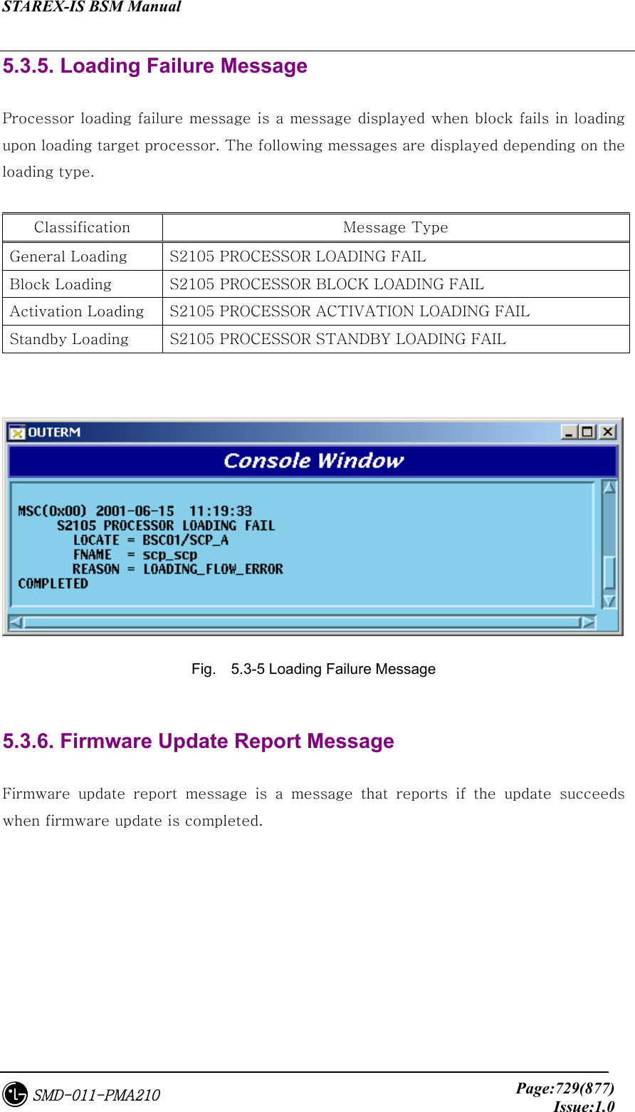
![STAREX-IS BSM Manual Page:842(877)Issue:1.0SMD-011-PMA210 to next initial alignment command word16 T22 240(sec) Local inhibit test timer3-6 minutes word16 T23 240(sec) Remote inhibit test timer3-6 minutes word16 SLTackT 5(sec) Time to wait for signal link test answer, with range of 4sec~12sec byte reserved[20] 0 7.5.7.5. St_SCCP_timer.dg Table 7.5-71 St_SCCP_timer Type N a m e default Remarks byte dummy 0 key word16 T_conne_est 20(sec) 1-2 minutes to wait connection confirm word16 T_ias 300(sec) Delay time of 5-10 minutes used to conduct inactivity test on connection section word16 T_iar 660(sec) Waiting time of 11-21 minutes to receive message on connection section byte T_rel 10(sec) Waiting time of 10-20 sec to receive release complete message word16 T_int 10(sec) 1. although implemented in source, it is not used. 2. upon connection release, it is the time to freeze corresponding LRN for a certain time to prevent the use of the same LRN Extending to 1 minutes word16 T_stat_info 30(sec) Interval that requests Subsystem status information Increasing value, 5-10 sec ~ 10-20 min byte reserve[20] 0 7.5.8. CCP/BSP COMMON 7.5.8.1. St_bts_data_type.dg Table 7.5-72 St_bts_data_type](https://usermanual.wiki/LG-Electronics-USA/3G1XOUTBTS.Users-Manual-Part-5/User-Guide-178517-Page-242.png)
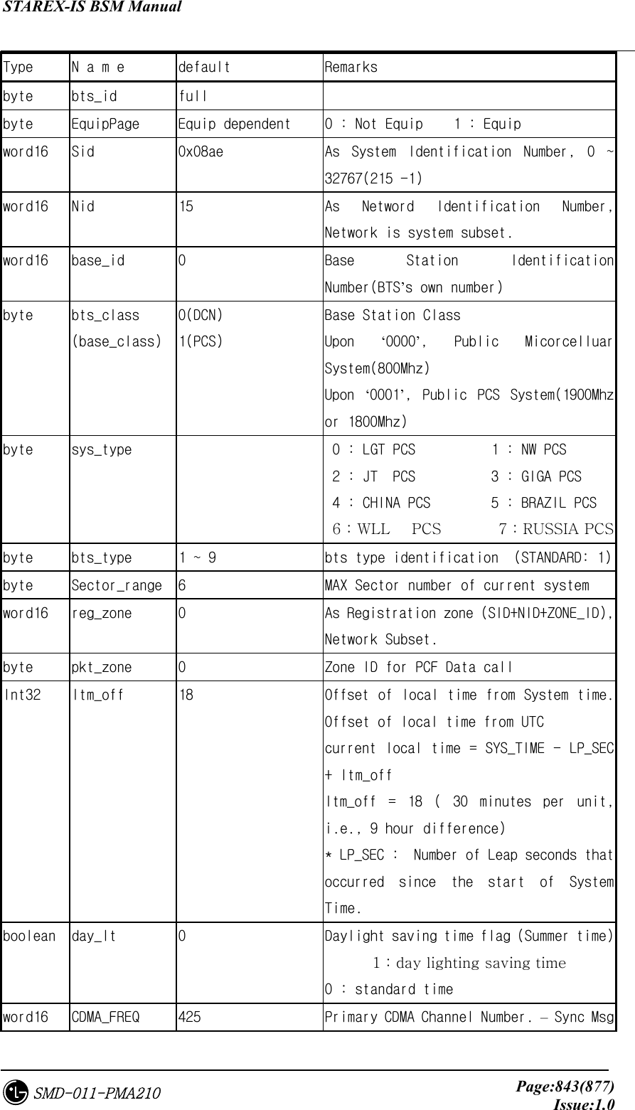
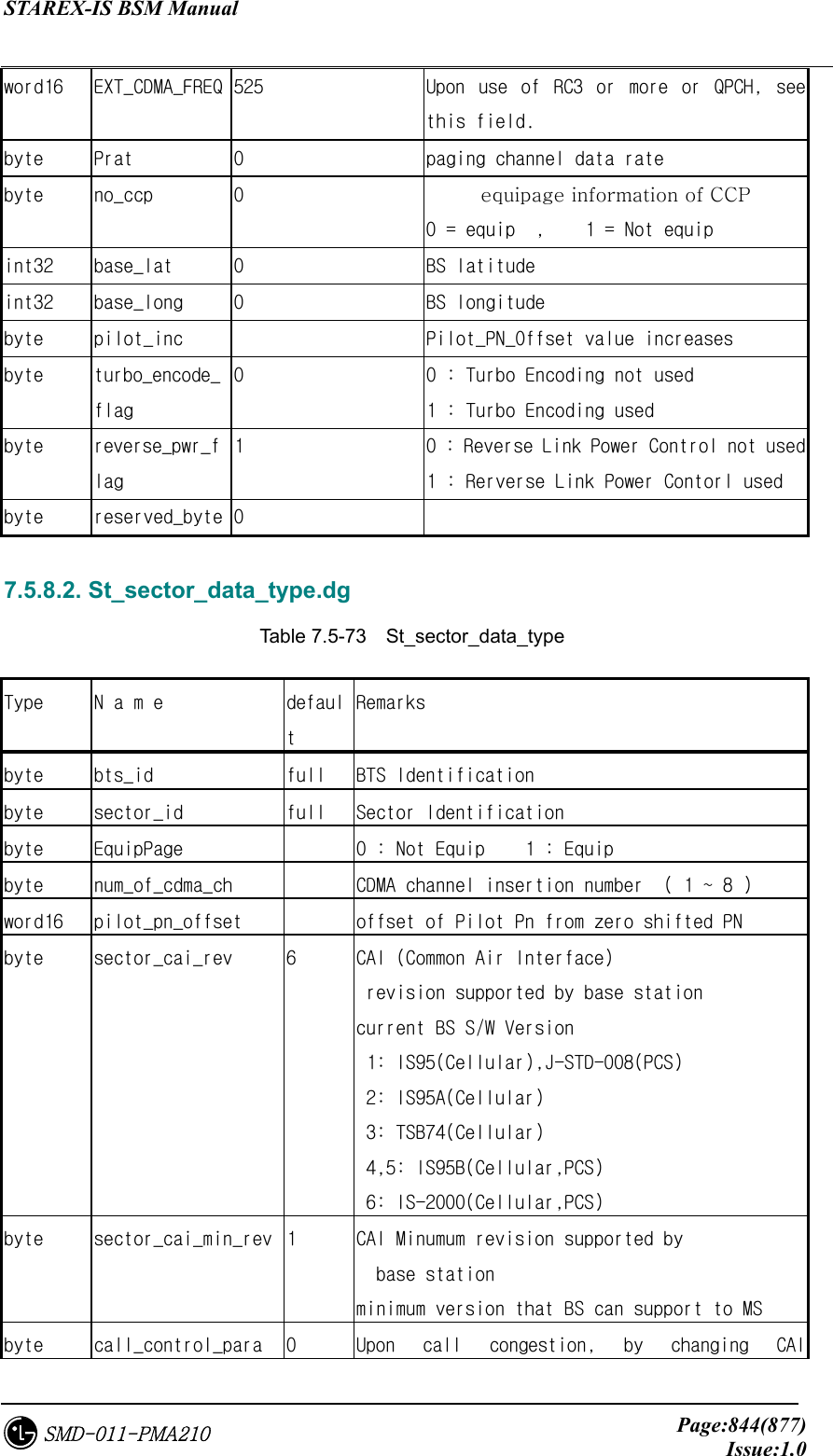
![STAREX-IS BSM Manual Page:845(877)Issue:1.0SMD-011-PMA210 revision, it can increase the number of calls that can be provided. Enable/disable flag of corresponding function. byte reserved_byte[32] 0 7.5.8.3. St_cdmach_data_type.dg Table 7.5-74 St_cdmach_data_type Type N a m e default Remarks byte bts_id full BTS Identification byte cdmach_id full CDMA Channel Identification byte EquipPage 0 : Not Equip 1 : Equip word16 freq_band 1800 Frequency Bandwidth word16 cdmach_num number of cdmach channel byte tce_reserved_4ho 20 Handoff preparatory traffic channel ratio ( %) byte MAX_SCH_ALLOC_RATE 50 Parameter to determine the upper limit of supplemental channel byte reserve[2] byte reserved_byte[34] 0 7.5.8.4. St_sys_param_msg_data_type.dg Table 7.5-75 St_sys_param_msg_data_type Type N a m e default Remarks byte bts_id full BTS Identification byte sector_id full Sector Identification byte cdmach_id full CDMA Channel Identification byte total_zones 2 Number of Registration Zones As the number of location registration to be held for use in Zone_based Registration, it can be saved up to 7EA, and if components more than it reside in ZONE_ LIST, MS removes the oldest component. byte zone_timer 2 When executing Zone-Based Registration, it](https://usermanual.wiki/LG-Electronics-USA/3G1XOUTBTS.Users-Manual-Part-5/User-Guide-178517-Page-245.png)
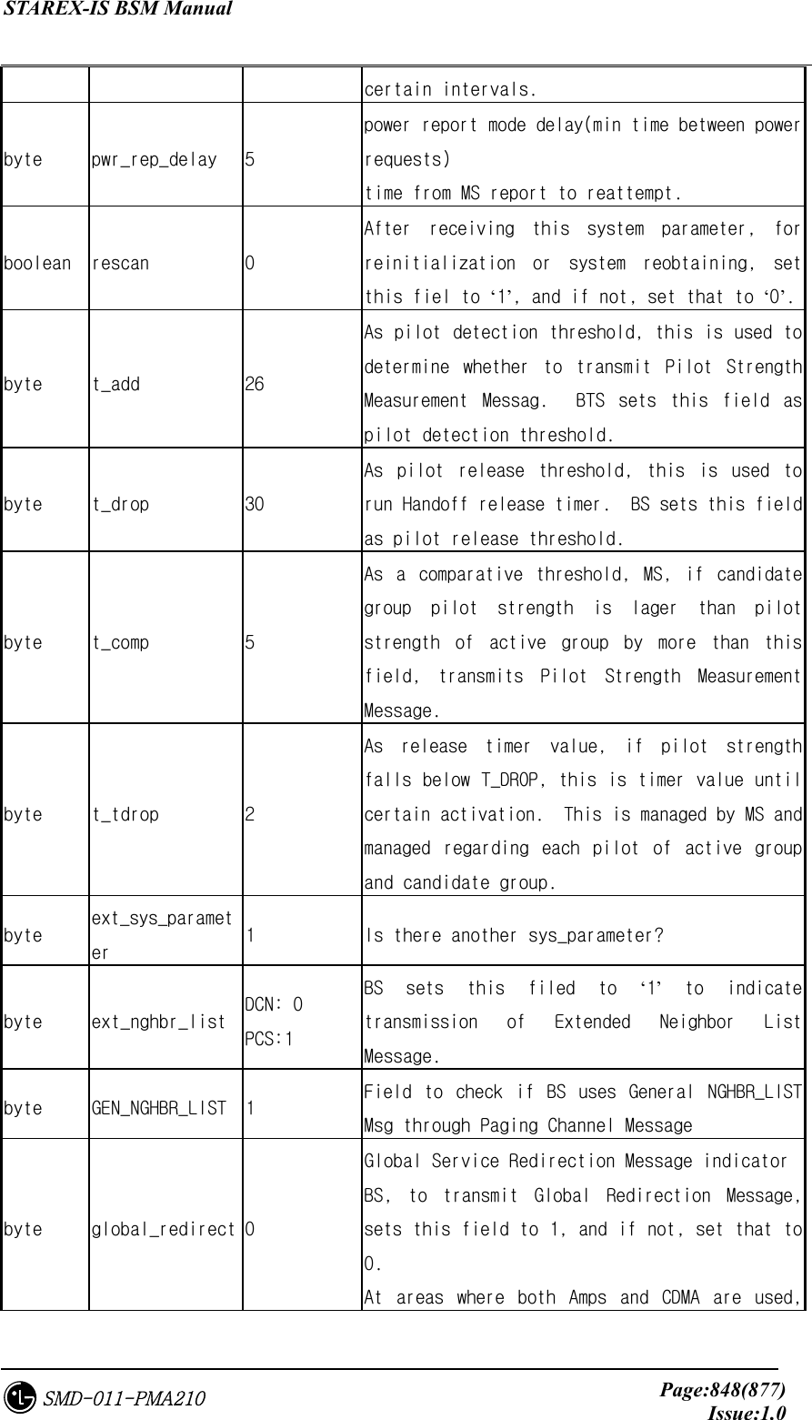
![STAREX-IS BSM Manual Page:847(877)Issue:1.0SMD-011-PMA210 boolean parameter_reg 1 Parameter-change registration indicator byte reg_prd 64 This is used for the calculation of MAX value counted to execute Timer based registration, and Timer based registration is executed when counter reaches REG_COUNT_MAX, and REG_COUNT_MAX is calculated as follows: REG_COUNT_MAX = [ 2reg_prd/4 ] word16 reg_dist 0 registration distance 0 : Personal Stations are not to perform distance based registration. Other than 0: Personal Stations are to perform distance based registration. ref : means 7.8m per unit. byte srch_win_a 7 search window size for the active set byte srch_win_n 9 search window size for the nghbr set byte srch_win_r 10 search window size for the Remaining set byte nghbr_max_age 1 Maximum age for retention of Neighbor set member byte pwr_rep_thresh 4 power control reporting threshold As power control report threshold, set thi snumber before MS measures TOT_FRAMES and BAD_FRAMES and reports corresponding message to BTS to transmit this value to BTS. byte pwr_rep_frames 7(frames) power control reporting frame count. Num fwd tc frames for Total count pwr_rep_frames = 2**(pwr_rep_frames/2) *5 boolean pwr_thresh_enable 0 Threshold report mode indicator if (1) then pwr_rep_thresh = 00000 If MS frame error rate reaches to threshold, it reports statistics. if (0) then it prevents that from its transmitting to MS. Boolean pwr_period_enable 0 Periodic report mode indicator if (0) then it prevents that from its sending periodic power measuremtn msg to to MS. if (1) then MS reports frame error rate at](https://usermanual.wiki/LG-Electronics-USA/3G1XOUTBTS.Users-Manual-Part-5/User-Guide-178517-Page-247.png)
![STAREX-IS BSM Manual Page:849(877)Issue:1.0SMD-011-PMA210 only one side should be used ( 0 : not changed 1 : change subject to message ) byte PRI_NGHBR_LIST Field for BS to check the status of Private NGHBR_LIST Msg through Paging Channel Message byte USER_ZONE_ID Field to check the status of User_zone_id Msg through Paging Channel Message byte EXT_GLOBAL_REDIRECT Field to check the status of Ext_global_redirection Msg through Paging Channel Message byte EXT_CHAN_LIST 1 Field to check the status of Ext_channel_list Msg through Paging Channel Message byte reserved_byte[32] 0 7.5.8.5. St_ext_sys_param_msg_data_type.dg Table 7.5-76 St_ext_sys_param_msg_data_type Type N a m e default Remarks byte bts_id full BTS Identification byte sector_id full Sector Identification byte cdmach_id full CDMA Channel Identification byte pref_msid_type 3 Preferred Access Channel Personal Station Identifier Type 010 : IMSI 011 : IMSI and ESN 110 : TMSI(valid TMSI is assigned) IMSI(TMSI not assigned) 111 : TMSI(valid TMSI is assigned) IMSI and ESN(TMSI not assigned) Other value is reserved. word16 mcc 349 Mobile Country Code byte imsi_11_12 99 imsi : International Mobile Station Identity imsi_11_12 is 11th, 12nd digits of imsi. byte tmsi_zone_len 4 TMSI(Temporary Mobile Station Identity) As temporary personal station identifier, it](https://usermanual.wiki/LG-Electronics-USA/3G1XOUTBTS.Users-Manual-Part-5/User-Guide-178517-Page-249.png)
![STAREX-IS BSM Manual Page:850(877)Issue:1.0SMD-011-PMA210 consists of tmsi_zone and tmsi_code. BS sets this field as the number of octet included in tmsi_zone. Byte tmsi_zone[8] 0 Length : 8*tmsi_zone_len byte bcast_index 6 To enable periodic broadcast paging, BS sets this field to ‘1~7’, and if not, set that to ‘0’. byte IMSI_T_SUPPORTED byte P_REV (8bit) 6 Protocol revision level BS sets this filed to ‘00000110’. 0 : 95 1 : JSTD-008 (PCS) 2 : 95A 3 : TSB74 4,5: 95B(based on completion ratio) – DCN, PCS byte MIN_P_REV (8bit) 1 Minimum protocol revision level. Sets protocol revision level that BS can offer to the minimum. Band Class0 : 2 , Band Class1 : 1 byte SOFT_SLOPE (6bit) Included in the formaula used upon Add/Drop of pilot to Active Set. BS sets this filed as unsigned. byte ADD_INTERCEPT (6) The intercept in the inequality criterion for adding a pilot to the Active Set BS sets this filed as complement of 3 in dB unit. byte DROP_INTERCEPT (6) The intercept in the inequality criterion for dropping a pilot to the Active Set BS sets this filed as complement of 3 in dB unit. byte MAX_NUM_ALT_SO (3) Maximum number of alternative service options. BS makes MS set the number that includes Origination Message or Page Response Message to this field. byte RESELECT_INCLUDED System reselection parameters included. If BS includes system reselection parameters,](https://usermanual.wiki/LG-Electronics-USA/3G1XOUTBTS.Users-Manual-Part-5/User-Guide-178517-Page-250.png)
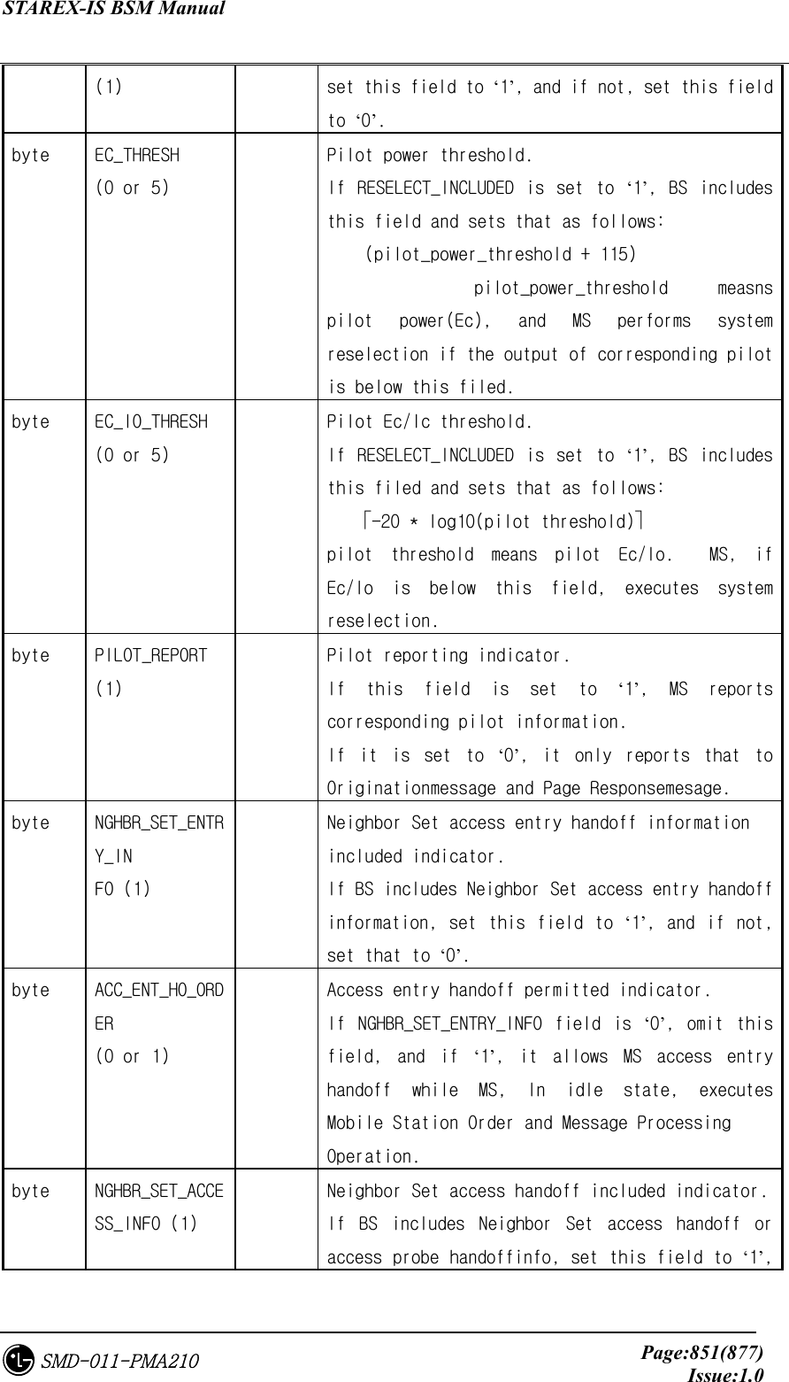
![STAREX-IS BSM Manual Page:854(877)Issue:1.0SMD-011-PMA210 (6) Configurations greater than 2. BS sets this field with reverse traffic channel power value. byte reserved_byte[33] 0 7.5.8.6. St_nghbr_list_msg_data_type.dg Table 7.5-77 St_nghbr_list_msg_data_type Type Name Default Remarks byte bts_id full BTS Identification byte sector_id full Sector Identification byte nghbrs_in_msg nghbr_list number held by one sector byte nghbr_srch_mode Parameter included in GNLM byte use_timing If Nghbr Base station transmits pilot in DTX mode, it indicates the use of timming information. byte global_timing_incl When use_timing is set to ‘1’, this indicates whether all neighbors use the same timing information. byte global_tx_duration As Pilot Transmission duration of Neighbor Base Station, it is valid only if all neighbors use the same value. byte global_tx_period Valid only if all neighbors use the same value with DTX cycle of Pilot Transmission of Neighbor Base Station. byte srch_offset_incl byte nghbr_config[ ] When the value of this field is as follows: 000 : upon handoff The personal station shall begin monitering the Paging Channel of the new base station, using the same Code Channel. 001 : The personal station shall begin monitergin the primary paging channel of the new base station. 010 : The nghbr base station has a different number of frequencies having Paging Channels as](https://usermanual.wiki/LG-Electronics-USA/3G1XOUTBTS.Users-Manual-Part-5/User-Guide-178517-Page-254.png)
![STAREX-IS BSM Manual Page:855(877)Issue:1.0SMD-011-PMA210 the current station. word16 nghbr_pn[ ] pilot_pn_offset pf sector word16 nghbr_sid[ ] system identification value of BS to which a sector belongs word16 nghbr_nid[ ] Network identification value of BS to which corresponding sector belongs word16 nghbr_base_id[ ] base_id value of neighbor BS byte nghbr_msc_id[] msc_id value byte nghbr_bsc_id[] bsc_id value byte nghbr_bts_id[ ] bts_id value Byte nghbr_sect_id[ ] Sector id value byte nghbr_msc_type[] 0 0 : local MSC 1 : remote MSC Necessary to determine Soft, Hard H/O upon H/O. For local MSC, Soft H/O is possible, and for remote MSC, Hard H/O is attempted. byte nghbr_bsc_type[] 0 0 : local BSC 1 : remote BSC Necessary to determine Soft, Hard H/O upon H/O. For local MSC, Soft H/O is possible, and for remote MSC, Hard H/O is attempted. byte nghbr_beacon_pn[] 0 indicator byte search_priority[] the search priority for the Pilot Channel corresponding to NGHBR_PN. Value Search Priority Value Search Priority 00 Low 01 Medium 02 High 11 Very high byte freq_incl[] Frequence included indicator. That is, if this field is 1, upon handiff, it uses channels on nghbr_band and nghbr_freq and if 0 , it uses current channel as is. byte nghbr_band[] If freq_incl field is set to ‘1’ band class of candidate frequency 800Mhz: 0 1800Mhz : 4 = domestic 1900Mhz: 1 = overseas](https://usermanual.wiki/LG-Electronics-USA/3G1XOUTBTS.Users-Manual-Part-5/User-Guide-178517-Page-255.png)
![STAREX-IS BSM Manual Page:856(877)Issue:1.0SMD-011-PMA210 word16 nghbr_freq[] If freq_incl field is set to ‘1’ this field to the CDMA channel Number freq_incl field is set to ‘0’ disregarded byte timing_incl[] B : MS moves at 2FA -> 5FA B is the value on 3,4,5FA. It is held by 5FA BS. If each Nghbr Sector transmits pilot in DTX mode, it indicates timing information. byte nghbr_tx_offset[] Transmission start offset value of each nghbr sector byte nghbr_tx_duration[] Pilot Transmission time value of each Nghbr Sector byte nghbr_tx_period[] Pilot DTX cycle value of each Nghbr Sector. byte srch_set[] To indicate the status of each Nghbr Pilot. byte add_pilot_rec_incl [] Indicates the status of additinal record regarding each Nghbr Pilot. byte nghbr_pilot_rec_type [] Additional Record Type(Information Type) Identification of each Nghbr Pilot byte td_pilot_otd_pwr[] OTD Transmit Power Level of each Nghbr Pilot byte srch_offset_nghbr[] Search Window offset value regarding each Neighbor Pilot byte access_entry_ho[] Should be repeated as many as NGHBR_SET_SIZE. Access entry handoff permitted when entering the System Access State. If before MS receives message through Paging Channel in idle state, and for response, it transits to System Access State, BS sets this field to 1 or not it sets that to 0 if access entry handoff is allowed. The order of ACCESS_ENTRY_HO is the same as that of Neighbor List Message, Extended Neighbor List Message or General Neighbor List Message. byte access_ho_allowed[] Should be repeated as many as NGHBR_SET_SIZE. Access handoff and access probe handoff](https://usermanual.wiki/LG-Electronics-USA/3G1XOUTBTS.Users-Manual-Part-5/User-Guide-178517-Page-256.png)
![STAREX-IS BSM Manual Page:857(877)Issue:1.0SMD-011-PMA210 permitted for the corresponding pilot while in the System Access State. If MS is in System Access State, BS sets this field to 1 or not it sets that to 0 if MS access handoff or access probe handoff is allowed. The order of ACCESS_HO_ALLOWED is the same as that of Neighbor List Message, Extended Neighbor List Message or General Neighbor List Message. byte reserved_byte[34] 0 7.5.8.7. St_Qos_param_data Table 7.5-78 St_Qos_param_data Type N a m e default Remarks byte bts_id full byte max_sch_rate byte reserved_byte[106] 72 + 34 7.5.9. BSP Layer 7.5.9.1. St_pwr_mgt_param_type.dg Table 7.5-79 St_pwr_mgt_param_type Type N a m e default Remarks byte sector_id full Sector Identification (0 ~ 2) byte cdmach_id full CDMA Channel Identification(0 ~ 7) byte T_rx_filter 0 Received total power filter update rate. Ms units, 1/2 step, 20/2 ~ 255 range byte G_rx_filter 0 Received total power filter delay contant. 1/256 step. 0/256 ~ 255/256 range byte G_tx_filter 0 Transmit power filter delay constant 1/256 step. 0/256 ~ 255/256 range](https://usermanual.wiki/LG-Electronics-USA/3G1XOUTBTS.Users-Manual-Part-5/User-Guide-178517-Page-257.png)
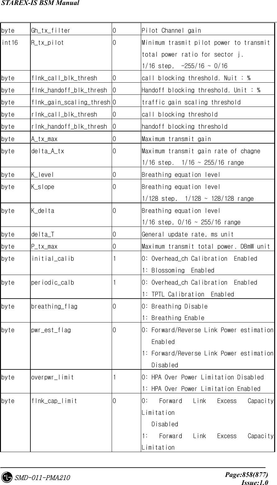
![STAREX-IS BSM Manual Page:859(877)Issue:1.0SMD-011-PMA210 Enabled byte rlnk_cap_limit 0 0: Reverse Link Excess Capacity Limitation Enabled 1: Reverse Link Excess Capacity Limitation Disabled byte reserved_byte[33] 0 7.5.9.2. St_txms_param_data.dg Table 7.5-80 St_txms_param_data Type N a m e default Remarks byte sector_id full Sector Identification byte cdmach_id full CDMA Channel Identification word16 ovhdch_erp 170(1.7W) Overhead Channel Effectiver Radiation Power and 170 means 1.7W(32dBm). word16 delta_erp No-use ERP calibration value word16 delta_sign No-use Calibration value symbol (0: PLUS, 1:MINUS) byte reserved_byte[32] 0 7.5.9.3. St_tic_data_type.dg Table 7.5-81 St_tic_data_type Type N a m e default Remarks byte sector_id full Sector Identification byte cdmach_id full CDMA Channel Identification byte primary_function 1 word16 tx_gain 0x900(2304) Overall sector transmit gain setting byte rx_a_atten No-use 255 Noise attenuator setting for the receiver A paths in 0.5 dB steps(0~63.5dB) byte rx_b_atten No-use 255 Noise attenuator setting for the receiver B paths in 0.5dB steps(0~63.5dB)](https://usermanual.wiki/LG-Electronics-USA/3G1XOUTBTS.Users-Manual-Part-5/User-Guide-178517-Page-259.png)
![STAREX-IS BSM Manual Page:860(877)Issue:1.0SMD-011-PMA210 byte tx_atten No-use 255 Noise attenuator setting for the transmit paths in 0.5 dB steps(0~63.5dB) boolean breathing No-use 0 Whether cell power “breathing” enabled. byte expected_db No-use 16 Cell breathing threshold in db. word16 power_upper_bound No-use 20 TICrecerse power threshold upper bound word16 power_lower_bound No-use 15 TICrecerse power threshold upper bound byte reserved_byte[33] 0 7.5.9.4. St_acc_param_data_type.dg Table 7.5-82 St_acc_param_data_type Type N a m e default Remarks byte sector_id full Sector Identification(0 ~ 2) byte cdmach_id full CDMA Channel Identification(0 ~ 7) byte pc_id full Paging Channel Identification(0 ~ 7) byte nom_pwr 0 Power control value for Open loop Power Control byte init_pwr 0 Initial power offset for access Power control value for Open Loop Power Control for MS Access Channelinitial transmission byte pwr_step 3 Power increment Power amount value increased by MS between continuous probes at Access Probe Sequence byte num_step 6 Number of access probe As the number of Access Probe, this is the value that is smaller by 1 than maximum access probe number transmitted from one Access Probe Sequence. byte max_cap_sz 3 Max Access Channel message capsule size As value that indicates maximum access channel message capsule size, BS sets this field to value that is smaller by 3 than access channel frame number. byte pam_sz 3 Access Channel preamble length As the length of access channel preamble, BS sets value that is smaller by 1 than access](https://usermanual.wiki/LG-Electronics-USA/3G1XOUTBTS.Users-Manual-Part-5/User-Guide-178517-Page-260.png)
![STAREX-IS BSM Manual Page:861(877)Issue:1.0SMD-011-PMA210 channel frame number transmitted from access 채channel preamble. byte psist_0_9 0 As value on access overload grade(0~9), if access pverload grade allows 0~9 MS to transmit request to access channel, BS sets that as continuous value to use this field and if not, it sets that to ‘111111’. byte psist_10 0 If test MS with access overlaod grade of 10 is allowed to transmit requests to access channel, BTS sets that as continuous value to use this field, and if not, it sets that to ‘111’. byte psist_11 0 If emergency MS with access overlaod grade of 11 is allowed to transmit requests to access channel, BTS sets that as continuous value to use this field, and if not, it sets that to ‘111’. byte psist_12 0 If MS with access overlaod grade of 12 is allowed to transmit requests to access channel, BTS sets that as continuous value to use this field, and if not, it sets that to ‘111’. byte psist_13 0 If MS with access overlaod grade of 13 is allowed to transmit requests to access channel, BTS sets that as continuous value to use this field, and if not, it sets that to ‘111’. byte psist_14 0 If MS with access overlaod grade of 14 is allowed to transmit requests to access channel, BTS sets that as continuous value to use this field, and if not, it sets that to ‘111’. byte psist_15 0 If MS with access overlaod grade of 15 is allowed to transmit requests to access channel, BTS sets that as continuous value to use this field, and if not, it sets that to ‘111’. byte msg_psist 0 As continuous transformer used to attempt accesschannel for message transfer, MS multiples [2-MSG_PSIST] to transmission probability.](https://usermanual.wiki/LG-Electronics-USA/3G1XOUTBTS.Users-Manual-Part-5/User-Guide-178517-Page-261.png)
![STAREX-IS BSM Manual Page:862(877)Issue:1.0SMD-011-PMA210 byte reg_psist 0 MS multiplies [2-MSG_PSIST] to transmission probability. byte probe_pn_ran 0 As a field related to time random for access channel probe, BS sets value of 0~9 so that the range of time random value is 2PROBE_PN_RAN-1 chip. byte acc_tmo 6 Answer time excessive value. byte probe_bkoff 0 Backoffrange of accesws channel probe byte bkoff 1 As access channel probe sequence backoff range, BS sets this field with the value that is lower by 1 than the number of slots that are delayed owing to backoff. byte max_req_seq 2 BS should set that with value greater than 0. byte max_rsp_seq 2 BS should set that with value greater than 0. byte auth 0 If MS includes standard authentication data inaccess channel nmessage, BTS sets this field to ‘01’, and if not it sets that to ‘00’. word32 rand 0 If auth field value is ‘01’, BTS sets this field to random attempt value to be used upon authentication and if different value, it is omitted. byte nom_pwr_ext 0(DCN) 1(PCS) extended nominal transmit power open loop power stimate: -24dB ~ -9dB if this field is ‘1’, -8dB ~ 7dB if this field is ‘0’ byte reserved_byte[35] 0 7.5.9.5. St_pc_global_redirect_msg_type.dg Table 7.5-83 St_pc_global_redirect_msg_type Type N a m e default Remarks byte sector_id full Sector Identification word16 redirect_accolc 65535 redirect ACCess OverLoad Class indicator byte return_if_fail 1 1: If personal system fails to redirect to other system, it allows entry to original](https://usermanual.wiki/LG-Electronics-USA/3G1XOUTBTS.Users-Manual-Part-5/User-Guide-178517-Page-262.png)
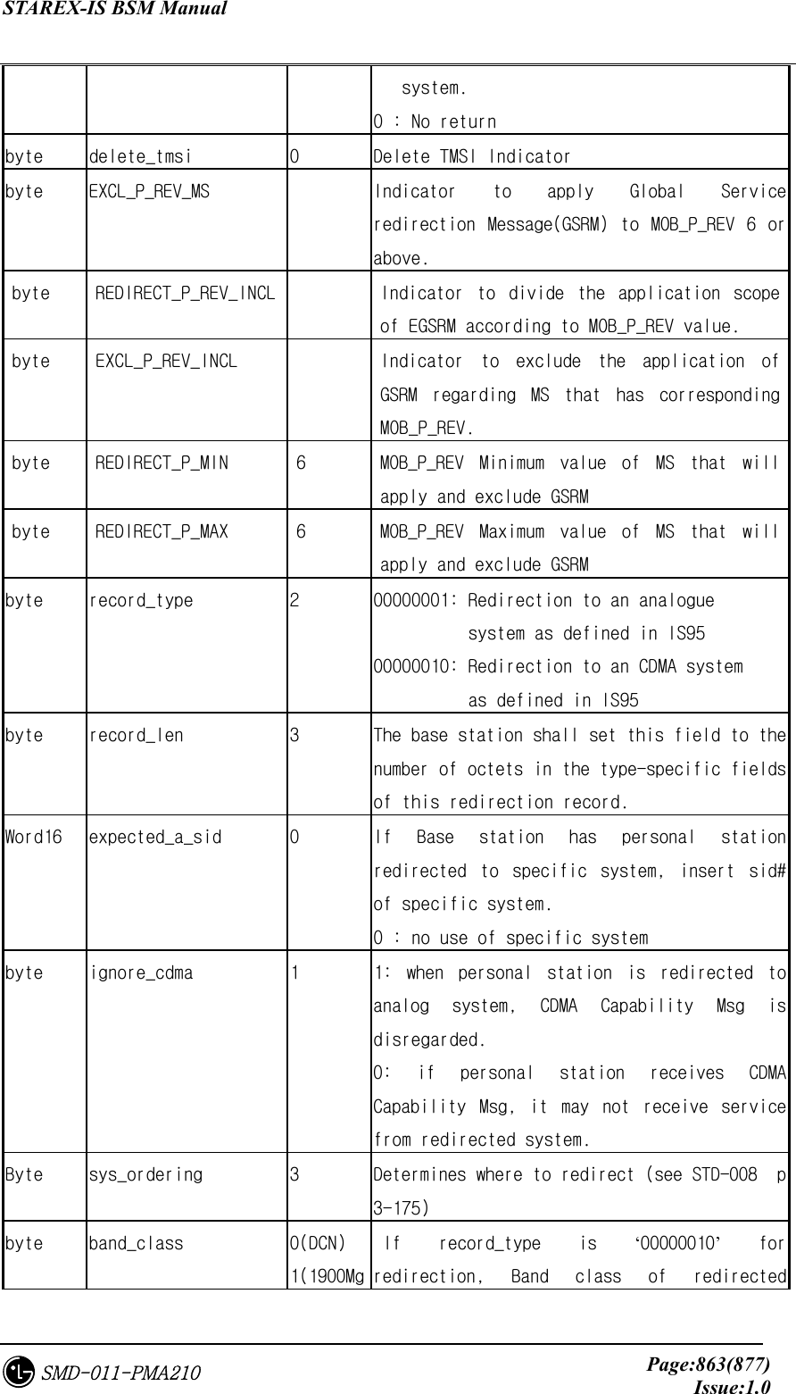
![STAREX-IS BSM Manual Page:864(877)Issue:1.0SMD-011-PMA210 z) 4(1800Mhz) system should be filled. 800Mhz: 0 1800Mhz : 4 = domestic 1900Mhz: 1 = overseas Word16 expected_sid 0 If Base station has personal system redirected to other system, this sets this field to SID of redirected system. Word16 expected_nid 0 If Base station has personal system redirected to other system, this sets this field to NID of redirected system. Byte num_chans 0 The number of occurence of cdma_chan FIELD word16 cdma_chan[10] 0 For each CDMA Channel on which the personal station is to attempt to acquire a CDMA system, the base station shall include one occurrence of this field specifying the associated CDMA Channel number. byte reserved_byte[34] 0 7.5.9.6. St_bts_cfg_type Table 7.5-84 St_bts_cfg_type Type N a m e default Remarks byte dummy_key full BYTE OVHD_MODE 0 0: Dynamic 1: Fix byte pa_type 2 RF type 0: PA_NEQ 1: HPA 2: LPA(MPD) 3:LPA(MILCOM) byte ant_type 0 ~ 3 0 : Standard 1 : OTA 2 : DAI 3 : DAI_OAI BYTE TX_DIVERSITY 0 ~ 1 0: Not Tx Diversity 1: Tx Diversity byte rx_duplex 0 ~ 1 0: Simplex_antenna 1: Duplex_antenna byte rx_diversity 0 ~ 1 current ‘1’ 0: Non_Diversity 1: Diversity rx_diversity:0, St_chip_config_data diversity_scale_2000:0 byte lna_type 0 : Not_Equip 1 : Equip](https://usermanual.wiki/LG-Electronics-USA/3G1XOUTBTS.Users-Manual-Part-5/User-Guide-178517-Page-264.png)
![STAREX-IS BSM Manual Page:865(877)Issue:1.0SMD-011-PMA210 When MIC C, D are used for subway, this file is set to ‘0’. byte ttrf_type[12] 0 0 : Not_Equip, 1 : Equip, 2 : Equip and Blocked. 4EA per sector among 12EA. byte fa_use 0: 1FA-6Sec 1; 2FA-3Sec byte risa_eqp 1 0: not equip, 1: equip byte reserved_byte[34] 0 Reserved Field 7.5.9.7. St_dru_chc_data_type Table 7.5-85 St_dru_chc_data_type Type N a m e default Remarks byte proc_id full 0~9 Processor Identification byte EquipPage 0:Not Equip 1:Equip BYTE CHC_STATE[MAX_CHC] Not_equip/Block/Unblock BYTE CHIP_STATE[MAX_CHC][MAX_CHIP] 0 Chip status per channel card Not_equip/Block/Unblock byte reserved_byte[33] 0 7.5.9.8. St_chip_config_data Table 7.5-86 St_chip_config_data Type N a m e default Remarks byte DUMMY full 0 byte num_chip_per_chc 2 word16 sector_gain[MAX_SECTORS] 208 sector gain(Normal Path) Range : 0~4095 word16 tx_div_sector_gain[MAX_SECTORS] 0 sector gain(Tx Diversity Path) Range : 0~4095 word16 sector_timing_adv[MAX_SECTORS] 320 Timing advance (Normal Path) Max : 1264](https://usermanual.wiki/LG-Electronics-USA/3G1XOUTBTS.Users-Manual-Part-5/User-Guide-178517-Page-265.png)
![STAREX-IS BSM Manual Page:866(877)Issue:1.0SMD-011-PMA210 word16 tx_div_timing_adv[MAX_SECTORS] 0 Timing advance (Tx Diversity Path) Max : 1264 byte sector_tx_io_format 0 (6 path or below) 2 (3 path or below) 0:tx_output_chipx1, 1: tx_output_chipx1_fir 2: tx_output_chipx2_fir word16 cell_radius 511 in units of PN chip byte rev_input_format 1 (6 path or below) 0 (3 path or below) 0:chipx8_rate_input, 1: chipx2_rate_input byte ant_enable[MAX_ANTENNAS] MAX_ANTENNAS = 12 byte ant_source[MAX_ANTENNAS] ? byte rev_cell_mode ? byte max_rach_fraction 10 MAX=32 word32 max_rach_separation 80 MAX=512 byte max_reach_fraction 10 MAX=32 word32 Max_reach_separation 80 MAX=512 byte enable_srch_win_adj 1 byte max_finger_per_chan95 6 MAX=6 byte max_finger_per_chan2000 8 MAX=8 byte usefully_rate_likely No-use 1 byte finger_thresh_adj_enable No-use ? byte channel_finger_limit No-use ? byte csm_mode 1 0:non_backward_compatible, 1: backward_compatible byte diversity_scale_2000 3 Range : 0~3 int min_search_energy_rach No-use 150 int min_search_energy_rc1 No-use 200 int min_search_energy_rc2 No-use 200 int min_search_energy_rc3 No-use 40 int min_search_energy_rc4 No-use 40 int min_search_energy_rc5 No-use int min_search_energy_rc6 No-use int override_search_energy_rach No-use](https://usermanual.wiki/LG-Electronics-USA/3G1XOUTBTS.Users-Manual-Part-5/User-Guide-178517-Page-266.png)
![STAREX-IS BSM Manual Page:867(877)Issue:1.0SMD-011-PMA210 int override_search_energy_rc1 No-use int override_search_energy_rc2 No-use int override_search_energy_rc3 No-use int override_search_energy_rc4 No-use int override_search_energy_rc5 No-use int override_search_energy_rc6 No-use word16 turbo_dtx_threshold No-use 240 word16 conv_dtx_threshold No-use 392 byte bin_size No-use byte integration_period No-use word16 srch_win_len[MAX_SECTORS] 1(traffic) Range : 1~32 byte reserved_byte[32] 0 7.5.9.9. St_hpbch_data Table 7.5-87 St_hpbch_data Type N a m e default Remarks BYTE SECTOR_ID 0 ~ 2 BYTE PILOT_GAIN pilot channel gain BYTE NUM_CDMA_CH number of cdma channel of hopping beacon WORD16 CDMA_FREQ[MAX_CDMACH] CDMA Channel Number for Hopping Beacon. BYTE BEACON_TX_OFFSET[MAX_CDMACH] Pilot beacon transmit time offset . Reading the value from Neighbor_list_msg_data.dg for setting. BYTE BEACON_TX_DURATION[MAX_CDMACH] Pilot beacon transmit time duration . Reading the value from Neighbor_list_msg_data.dg and setting. BYTE BEACON_TX_PERIOD[MAX_CDMACH] Pilot beacon transmit time . Reading the value from Neighbor_list_msg_data.dg and setting. byte reserved_byte[32] 0](https://usermanual.wiki/LG-Electronics-USA/3G1XOUTBTS.Users-Manual-Part-5/User-Guide-178517-Page-267.png)
![STAREX-IS BSM Manual Page:868(877)Issue:1.0SMD-011-PMA210 7.5.9.10. St_pich_data_type (Pilot Channel) Table 7.5-88 St_pich_data_type (Pilot Channel) Type N a m e default Remarks BYTE SECTOR_ID 0 ~ 2 BYTE CDMACH_ID 0 ~ 7 BYTE PROC_ID PILOT CHANNEL PROCESSOR NUMBER (RCP) BYTE SLOT PILOT CHANNEL SLOT NUMBER BYTE PILOT_GAIN 234 pilot channel gain. in unit of dB BYTE PILOT_TD_GAIN piot tx_diversity channel gain. byte reserved_byte[34] 0 7.5.9.11. St_synch_data_type (Sync Channel) Table 7.5-89 St_synch_data_type (Sync Channel) Type N a m e default Remarks BYTE SECTOR_ID full 0 ~ 2 BYTE CDMACH_ID full 0 ~ 7 BYTE PROC_ID SYNCH PROCESSOR NUMBER (RCP) BYTE SLOT SYNCH SLOT NUMBER BYTE SYNC_GAIN 159 sync channel gain. in unit of dB byte reserved_byte[35] 0 7.5.9.12. St_pch_data_type (Paging Channel) Table 7.5-90 St_pch_data_type (Paging Channel) Type N a m e default Remarks byte sector_id full 0 ~ 2 byte cdmach_id full 0 ~ 7 byte pc_id full 0 ~ 6 byte equipage Actual pc equip state byte num_ac Access channel number per Paging Channel Access Para AccChan](https://usermanual.wiki/LG-Electronics-USA/3G1XOUTBTS.Users-Manual-Part-5/User-Guide-178517-Page-268.png)
![STAREX-IS BSM Manual Page:869(877)Issue:1.0SMD-011-PMA210 byte proc_id Paging channel processor number (RCP) byte slot Paging channel slot number BYTE PC_GAIN 217 Paging channel tx gain. in unit of dB byte frame_duration 2 Packet frame size. (5ms/20ms) Range : 0~4 (2:20ms) byte data_rate 0 data rate. Range : 0~1(0:9600bps, 1:4800bsp) byte encoding_rate No-use 1 Convolutional channel coding rate. byte reserved_byte[34] 0 7.5.9.13. St_qpch_data_type (Quick Paging Channel) Table 7.5-91 St_qpch_data_type (Quick Paging Channel) Type N a m e default Remarks BYTE SECTOR_ID full 0 ~ 2 BYTE CDMACH_ID full 0 ~ 7 BYTE QPCH_ID full 0 ~ 2 byte equipage BYTE PROC_ID QPCH PROCESSOR NUMBER (RCP) BYTE SLOT QPCH SLOT NUMBER BYTE INDICATOR_GAIN Paging indicator part gain BYTE CCI_GAIN CCI(Configuration Change Indicator) Gain byte frame_duration 2 Packet frame size. (5ms/20ms) byte data_rate 0 data rate. byte encoding_rate No-use Convolutional channel coding rate. byte reserved_byt[34] 0 7.5.9.14. St_ach_data_type (Access Channel) Table 7.5-92 St_ach_data_type (Access Channel) Type N a m e default Remarks](https://usermanual.wiki/LG-Electronics-USA/3G1XOUTBTS.Users-Manual-Part-5/User-Guide-178517-Page-269.png)
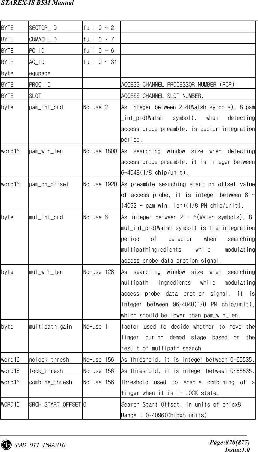
![STAREX-IS BSM Manual Page:871(877)Issue:1.0SMD-011-PMA210 WORD16 SRCH_WIN_SIZE 4(access) Search Window Size. in units of 64PN chip. Range : 1~32(64 PN Chips units) byte reserved_byte[35] 0 7.5.9.15. St_apich_data_type (Auxiliary Pilot Channel) Table 7.5-93 St_apich_data_type (Auxiliary Pilot Channel) Type N a m e default Remarks BYTE SECTOR_ID full 0 ~ 2 BYTE CDMACH_ID full 0 ~ 7 BYTE PROC_ID APICH PROCESSOR NUMBER (RCP) BYTE SLOT APICH SLOT NUMBER byte reserved_byte[32] 0 7.5.9.16. St_bcch_data_type (Broadcast Channel) Table 7.5-94 St_bcch_data_type (Broadcast Channel) Type N a m e default Remarks BYTE SECTOR_ID full 0 ~ 2 BYTE CDMACH_ID full 0 ~ 7 BYTE BCCH_ID full 0 ~ 6 byte equipage BYTE PROC_ID Broad CHANNEL PROCESSOR NUMBER (RCP) BYTE SLOT Broad CHANNEL SLOT NUMBER byte TX_GAIN byte SPREADING_RATE byte OTD byte SR1_BCN byte SR1_BRAT byte SR1_NON_OTD_INCL byte SR1_CDMA_FREQ_NON_OTD byte SR1_BCCH_RATE_NON_OTD](https://usermanual.wiki/LG-Electronics-USA/3G1XOUTBTS.Users-Manual-Part-5/User-Guide-178517-Page-271.png)
![STAREX-IS BSM Manual Page:872(877)Issue:1.0SMD-011-PMA210 byte SR1_OTD_INCL byte SR1_CDMA_FREQ_OTD byte SR1_BCCH_RATE_OTD byte SR3_CAP_IND byte SR3_CDMA_FREQ byte SR3_BCN byte SR3_BRAT byte frame_duration Packet frame size. (5ms/20ms) byte data_rate data rate. byte radio_configuration (encoding_rate) Convolutional channel coding rate. Radio configuration byte reserved_byte[34] 0 7.5.9.17. St_cpch_data_type (Common Power Control Channel) Table 7.5-95 St_cpch_data_type (Common Power Control Channel) Type N a m e default Remarks BYTE SECTOR_ID full 0 ~ 2 BYTE CDMACH_ID full 0 ~ 7 BYTE CPCH_ID full 0 ~ 6 byte equipage BYTE PROC_ID CPCH PROCESSOR NUMBER (RCP) BYTE SLOT CPCH SLOT NUMBER byte frame_duration Packet frame size. (5ms/20ms) byte data_rate data rate. byte radio_configuration (encoding_rate) Convolutional channel coding rate. Radio configuration byte reserved_byte[32] 0](https://usermanual.wiki/LG-Electronics-USA/3G1XOUTBTS.Users-Manual-Part-5/User-Guide-178517-Page-272.png)
![STAREX-IS BSM Manual Page:873(877)Issue:1.0SMD-011-PMA210 7.5.9.18. St_cach_data_type (Common Assignment Channel) Table 7.5-96 St_cach_data_type (Common Assignment Channel) Type N a m e default Remarks BYTE SECTOR_ID full 0 ~ 2 BYTE CDMACH_ID full 0 ~ 7 BYTE CACH_ID full 0 ~ 6 byte equipage BYTE PROC_ID CACH PROCESSOR NUMBER (RCP) BYTE SLOT CACH SLOT NUMBER byte frame_duration Packet frame size. (5ms/20ms) byte data_rate data rate. byte radio_configuration (encoding_rate) Convolutional channel coding rate. Radio configuration byte reserved_byte[32] 0 7.5.9.19. St_fccch_data_type (Forward Common Control Channel) Table 7.5-97 St_fccch_data_type (Forward Common Control Channel) Type N a m e default Remarks BYTE SECTOR_ID full 0 ~ 2 BYTE CDMACH_ID full 0 ~ 7 BYTE FCCCH_ID full 0 ~ 6 byte equipage BYTE PROC_ID FCCCH PROCESSOR NUMBER (RCP) BYTE SLOT FCCCH SLOT NUMBER byte frame_duration Packet frame size. (5ms/20ms) byte data_rate Data rate. byte radio_configuration (encoding_rate) Convolutional channel coding rate. Radio configuration byte reserved_byte[32] 0](https://usermanual.wiki/LG-Electronics-USA/3G1XOUTBTS.Users-Manual-Part-5/User-Guide-178517-Page-273.png)
![STAREX-IS BSM Manual Page:874(877)Issue:1.0SMD-011-PMA210 7.5.9.20. St_each_data_type (Enhanced Access Channel) Table 7.5-98 St_each_data_type (Enhanced Access Channel) Type N a m e default Remarks BYTE SECTOR_ID full 0 ~ 2 BYTE CDMACH_ID full 0 ~ 7 BYTE FCCCH_ID or CACH_ID full 0 ~ 6 BYTE EACH_ID full 0 ~ 31 byte equipage BYTE DUPLEX_ID 0 ~ 1 Redundancy BYTE PROC_ID EACH PROCESSOR NUMBER (RCP) BYTE SLOT EACH SLOT NUMBER BYTE reserved_byte[33] 0 7.5.9.21. St_rccch_data_type (Reverse Common Control Channel) Table 7.5-99 St_rccch_data_type (Reverse Common Control Channel) Type N a m e default Remarks BYTE SECTOR_ID full 0 ~ 2 BYTE CDMACH_ID full 0 ~ 7 BYTE FCCCH_ID or CACH_ID full 0 ~ 6 BYTE RCCH_ID full 0 ~ 31 byte equipage BYTE PROC_ID EACH PROCESSOR NUMBER (RCP) BYTE SLOT EACH SLOT NUMBER BYTE reserved_byte[34] 0 7.5.9.22. St_sector_cdmach_data_type Table 7.5-100 St_sector_cdmach_data_type type Name default Remarks byte sector_id full](https://usermanual.wiki/LG-Electronics-USA/3G1XOUTBTS.Users-Manual-Part-5/User-Guide-178517-Page-274.png)
![STAREX-IS BSM Manual Page:875(877)Issue:1.0SMD-011-PMA210 byte cdmach_id full byte ocns_enable 0 0: Ocns Enabled 1: Ocns Disabled byte num_of_ocns_ch 0 Ocns Call Number ( 0 ~ 20 ) byte ocns_test_data 5 Test Data Rate ( 0 ~ 5 ) ( B, 1/8, 1/4, 1/2, 1, V) word16 ocns_so 0x801f Service Option [ Markov(8002, 801f), LB(2,9) ] byte block_state 0 0: Unblock, 1: Block If current sector FA is ‘block’, MS regards no FA residing in channel list. byte reserved_byte[32] 0 7.5.9.23. St_HW_reset_type Table 7.5-101 St_HW_reset_type type Name default Remarks byte dummy_key 0 byte shlf_pwr[20] CSD : BSBB(0), RCBB0(1), RCBB1(2), RCBB2(3), RCBB3(4) COU : BCCB0(5), BCCB1(6), BCCB2(7), BCCB3(8) 9 ~ 19 : Reseved byte bspa[4][2] 0 byte lica[4] 0 byte aria[4] 0 byte bada 0 byte risa 0 byte bota 0 byte dran 0 byte rcpa[4][2] 0 byte mcpa[4][10] 0 byte buda[4][6] 0 byte paca[4] 0 byte pa[6][6] 0 byte bcra[2] 0](https://usermanual.wiki/LG-Electronics-USA/3G1XOUTBTS.Users-Manual-Part-5/User-Guide-178517-Page-275.png)
![STAREX-IS BSM Manual Page:876(877)Issue:1.0SMD-011-PMA210 byte bppa byte reserved_byte[23] 0 7.5.9.24. St_Chip_pwr_cntl_para_data( 0:FCH , 1:SCH, 2:SCCH, 3:DCCH ) Table 7.5-102 St_Chip_pwr_cntl_para_data Type N a m e default Remarks byte Dummy 0 byte Channel_pwr[MAX_CH_TYPE(4)] 224 Forward Traffic Channel Tx Power 0(-63.5dB) ~ 127(0dB). 0.5dB step byte Data_gain No-use Data Gain to be added to the Channel Power -31.75dB ~ 31.75dB. 0.5dB step byte Pwr_cntl_gain No-use Power Control Sub-channel Gain to be added to the Channel. –31.75dB ~ 31.75dB, 0.5dB step. byte Min_gain[MAX_CH_TYPE(4)] 150 Forward Traffic Channel Power Minimum Value byte max_gain[MAX_CH_TYPE(4)] 224 Forward Traffic Channel Power Maximum Value byte step_up_size 4 Forward Traffic Channel Power Control step up size. 0(0dB) ~ 15(3.75dB), 0.25dB step byte step_dn_size 4 Forward Traffic Channel Power Control step down size. 0(0dB) ~ 15(3.75dB), 0.25dB step byte fpc_punc_mode 0 FPC(Forward Power Control) Puncture Mode. Same as fpc_mode of St_pwr_cntl_para_type byte rpc_punc_mode 0 RPC(Reverse Power Control) Puncture Mode. byte pwr_cntl_set_point 219 RPC Set Point(Threshold) 0(-63.75dB) ~ 255(0dB), 0.25dB step byte pwr_cntl_pattern 3 Power Control Up/Down pattern to be used when no fingers are combining byte Reserved_byte[32]](https://usermanual.wiki/LG-Electronics-USA/3G1XOUTBTS.Users-Manual-Part-5/User-Guide-178517-Page-276.png)