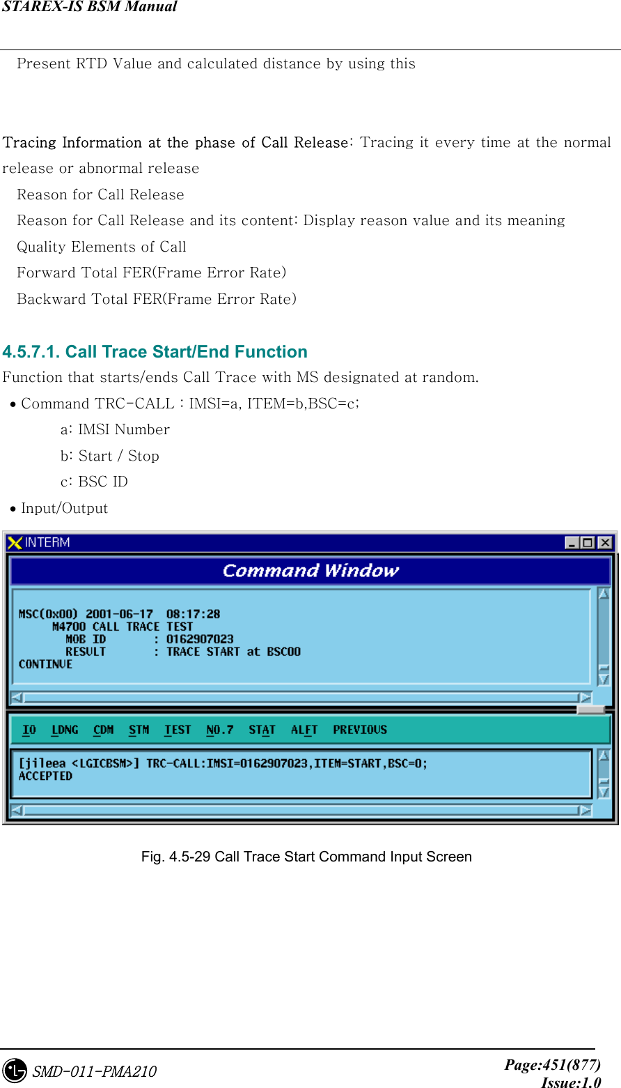
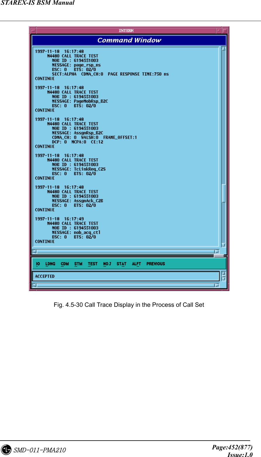
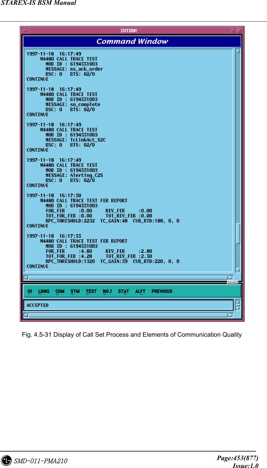
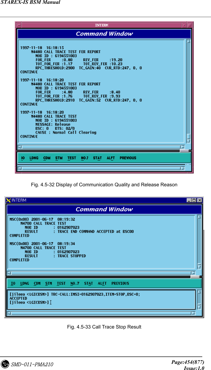
LG Electronics USA 3G1XOUTBTS STAREX-IS 1900 Outdoor BTS User Manual STAREX IS User s Manual
LG Electronics USA STAREX-IS 1900 Outdoor BTS STAREX IS User s Manual
Contents
- 1. Users Manual Part 1
- 2. Users Manual Part 2
- 3. Users Manual Part 3
- 4. Users Manual Part 4
- 5. Users Manual Part 5
Users Manual Part 2
![STAREX-IS BSM Manual Page:318(877)Issue:1.0SMD-011-PMA210 4.3.6. Network Parameter Information Change (Change_Parameter_Info_3) 4.3.6.1. CAN INTER BSC AAL2 Setting Information Change • Command CHG-CAN-IUR: BSC=a, [BSC0_AAL2=b], [BSC1_AAL2=c], [BSC2_AAL2=d], [BSC3_AAL2=e], [BSC4_AAL2=f], [BSC5_AAL2=g], [BSC6_AAL2=h], [BSC7_AAL2=i], [BSC8_AAL2=j],[BSC9_AAL2=k],[BSC10_AAL2=l], [BSC11_AAL2=m], [NO_AAL2_VC=n]; • Input CHG-CAN-IUR: BSC=0, BSC0_AAL2=255 • Output](https://usermanual.wiki/LG-Electronics-USA/3G1XOUTBTS.Users-Manual-Part-2/User-Guide-178514-Page-1.png)
![STAREX-IS BSM Manual Page:319(877)Issue:1.0SMD-011-PMA210 4.3.6.2. CAN INTER BSC AAL5 Setting Information Change • Command CHG-CAN-BSC: [CAN0_START_AAL5=a], [CAN1_START_AAL5=b], [NO_AAL5_VC=0~], a ,b: 0~0xffffff c: 0~ • Input CHG-CAN-BSC: CAN0_START_AAL5=255 • Output](https://usermanual.wiki/LG-Electronics-USA/3G1XOUTBTS.Users-Manual-Part-2/User-Guide-178514-Page-2.png)
![STAREX-IS BSM Manual Page:320(877)Issue:1.0SMD-011-PMA210 4.3.6.3. CPN INTER DATA AAL5 Setting Information Change • Command CHG-CPN-DATA: [BSC0_AAL5=a], [BSC1_AAL5=b], [BSC2_AAL5=c], [BSC3_AAL5=d], [BSC4_AAL5=e], [BSC5_AAL5=f], [BSC6_AAL5=g], [BSC7_AAL5=h], [BSC8_AAL5=i], [BSC9_AAL5=j], [BSC10_AAL5=k], [BSC11_AAL5=l], [NO_AAL5_VC=m]; a ~n: BSC AAL5 (32~0xffffff) m: 0~32 • Input CHG-CPN-DATA: BSC0_AAL5=255; • Output](https://usermanual.wiki/LG-Electronics-USA/3G1XOUTBTS.Users-Manual-Part-2/User-Guide-178514-Page-3.png)
![STAREX-IS BSM Manual Page:321(877)Issue:1.0SMD-011-PMA210 4.3.6.4. CPN INTER PCF AAL5 Setting Information Change • Command CHG-CPN-PCF: [PIP0_0_AAL5=a], [PIP0_1_AAL5=b], [PIP1_0_AAL5=c], [PIP1_1_AAL5=d], [PIP2_0_AAL5=e], [PIP2_1_AAL5=f], [PIP3_0_AAL5=g], [PIP3_1_AAL5=h], [PIP4_0_AAL5=i], [PIP4_1_AAL5=j], [PIP5_0_AAL5=k], [PIP5_1_AAL5=l], [PIP6_0_AAL5=m], [PIP6_1_AAL5=n], [PIP7_0_AAL5=o], [PIP7_1_AAL5=p], [PIP8_0_AAL5=q], [PIP8_1_AAL5=r], [PIP9_0_AAL5=s], [PIP9_1_AAL5=t], [PIP10_0_AAL5=u], [PIP10_1_AAL5=v], [NO_AAL5_VC=w] a~v: PIP AAL5 (32~0xffffff) w: 0~480 • Input CHG-CPN-PCF: PIP0_0_AAL5=255 ; • Output](https://usermanual.wiki/LG-Electronics-USA/3G1XOUTBTS.Users-Manual-Part-2/User-Guide-178514-Page-4.png)
![STAREX-IS BSM Manual Page:322(877)Issue:1.0SMD-011-PMA210 4.3.6.5. BSC INTER BSC AAL2 Setting Information Change • Command CHG-BSC-IUR: BSC=a, [BSC0_AAL2=b], [BSC1_AAL2=c], [BSC2_AAL2=d], [BSC3_AAL2=e], [BSC4_AAL2=f], [BSC5_AAL2=g], [BSC6_AAL2=h], [BSC7_AAL2=i], [BSC8_AAL2=j], [BSC9_AAL2=k], [BSC10_AAL2=l], [BSC11_AAL2=m], [NO_AAL2_VC=n]; a : BSC Number(0~11) b~m: BSC AAL2 (0~0xffffff) n: 0~ • Input CHG-BSC-IUR: BSC=0, BSC0_AAL2=255; • Output](https://usermanual.wiki/LG-Electronics-USA/3G1XOUTBTS.Users-Manual-Part-2/User-Guide-178514-Page-5.png)
![STAREX-IS BSM Manual Page:323(877)Issue:1.0SMD-011-PMA210 4.3.6.6. BSC INTER BTSC AAL2 Setting Information Change • Command CHG-BSC-IUB: BSC=a, BTS=b, LICA=c, LINK=d, [LINK0_AAL2=e], [LINK1_AAL2=f], [LINK2_AAL2=g], [LINK3_AAL2=h], [LINK4_AAL2=i], [LINK5_AAL2=j], [LINK6_AAL2=k], [LINK7_AAL2=l], [LINK8_AAL2=m], [LINK9_AAL2=n], [LINK10_AAL2=o], [LINK11_AAL2=p], [LINK12_AAL2=q], [LINK13_AAL2=r], [LINK14_AAL2=s], [LINK15_AAL2=t] a : BSC Number(0~11) b : BTS Number(0~47) c : LICA Number(0~2) d : LINK Number(0~15) e~t: 0~0xffffff • Input CHG-BSC-IUB: BSC=0, BTS=0, LICA=0, LINK0_AAL2=255; • Output](https://usermanual.wiki/LG-Electronics-USA/3G1XOUTBTS.Users-Manual-Part-2/User-Guide-178514-Page-6.png)
![STAREX-IS BSM Manual Page:324(877)Issue:1.0SMD-011-PMA210 4.3.6.7. BSC INTER CAN AAL2/5 Setting Information Change • Command CHG-BSC-CAN: BSC=a, [CAN0_START_AAL5=b], [CAN1_START_AAL5=c], [NO_AAL5_VC=d] a: BSC Number(0~11) b,c: 32~0xffffff d: 0~8160 • Input CHG-BSC-CAN: BSC=0, CAN0_START_AAL5=255; • Output](https://usermanual.wiki/LG-Electronics-USA/3G1XOUTBTS.Users-Manual-Part-2/User-Guide-178514-Page-7.png)
![STAREX-IS BSM Manual Page:325(877)Issue:1.0SMD-011-PMA210 4.3.6.8. BSC INTER SLB AAL5 Setting Information • Command CHG-BSC-SLB: BSC=a, [SLP0_AAL5=b], [SLP1_AAL5=c], [SLP2_AAL5=d], [SLP3_AAL5=e], [SLP4_AAL5=f], [SLP5_AAL5=g], [SLP6_AAL5=h], [SLP7_AAL5=i], [SLP8_AAL5=j], [SLP9_AAL5=k], [SLP10_AAL5=l], [SLP11_AAL5=m], [SLP12_AAL5=n], [SLP13_AAL5=o], [SLP14_AAL5=p], [SLP15_AAL5=q], [SLP16_AAL5=r], [SLP17_AAL5=s], [NO_AAL5_VC=t] a: BSC Number(0~11) b~s: 40~0xffffff t: 0~984 • Input CHG-BSC-SLB: BSC=0, SLP0_AAL5=255; • Output](https://usermanual.wiki/LG-Electronics-USA/3G1XOUTBTS.Users-Manual-Part-2/User-Guide-178514-Page-8.png)
![STAREX-IS BSM Manual Page:326(877)Issue:1.0SMD-011-PMA210 4.3.6.9. BSC INTER VCB AAL5 Setting Information Change • Command CHG-BSC-VCB: BSC=a, [VCP0_AAL5=b], [VCP1_AAL5=c], [VCP2_AAL5=d], [VCP3_AAL5=e], [VCP4_AAL5=f], [VCP5_AAL5=g], [VCP6_AAL5=h], [VCP7_AAL5=i], [VCP8_AAL5=j], [VCP9_AAL5=k], [VCP10_AAL5=l], [VCP11_AAL5=m], [VCP12_AAL5=n], [VCP13_AAL5=o], [VCP14_AAL5=p], [VCP15_AAL5=q], [NO_AAL5_VC=r] a: BSC Number(0~11) b~q: 40~0xffffff r: 0~88 • Input CHG-BSC-VCB: BSC=0, VCP0_AAL5=255; • Output](https://usermanual.wiki/LG-Electronics-USA/3G1XOUTBTS.Users-Manual-Part-2/User-Guide-178514-Page-9.png)
![STAREX-IS BSM Manual Page:327(877)Issue:1.0SMD-011-PMA210 4.3.6.10. BSC INTER ALB AAL5 Setting Information Change • Command CHG-BSC-ALB: BSC=a, [ALMA0_ALP0_0=b], [ALMA0_ALP0_1=c], [ALMA0_ALP1_0=d], [ALMA0_ALP1_1=e], [ALMA0_ALP2_0=f], [ALMA0_ALP2_1=g], [ALMA0_ALP3_0=h], [ALMA0_ALP3_1=i], [ALMA0_ALP4_0=j], [ALMA0_ALP4_1=k], [ALMA1_ALP0_0=l], [ALMA1_ALP0_1=m], [ALMA1_ALP1_0=n], [ALMA1_ALP1_1=o], [ALMA1_ALP2_0=p], [ALMA1_ALP2_1=q], [ALMA1_ALP3_0=r], [ALMA1_ALP3_1=s], [ALMA1_ALP4_0=t], [ALMA1_ALP4_1=u], [NO_AAL5_VC=v] a: BSC Number(0~11) b~u: 32~0xffffff v: 0~2016 • Input CHG-BSC-ALB: BSC=0, ALMA0_ALP0_0=255; • Output](https://usermanual.wiki/LG-Electronics-USA/3G1XOUTBTS.Users-Manual-Part-2/User-Guide-178514-Page-10.png)
![STAREX-IS BSM Manual Page:328(877)Issue:1.0SMD-011-PMA210 4.3.6.11. BTS INTER RCU AAL5 Setting Information Change • Command CHG-BTS-RCU: BSC=a, BTS=b, RCU=c, [LICA0_AAL5=d], [LICA1_AAL5=e], [LICA2_AAL5=f], [LICA0_NO_VC=g], [LICA1_NO_VC=h], [LICA2_NO_VC=i] a: BSC Number(0~11) b:BTS Number(0~47) c: RCU Number(0~9) d~i: 0~ • Input CHG-BTS-RCU: BSC=0,BTS=0,RCU=0, LICA0_AAL5=255; • Output](https://usermanual.wiki/LG-Electronics-USA/3G1XOUTBTS.Users-Manual-Part-2/User-Guide-178514-Page-11.png)
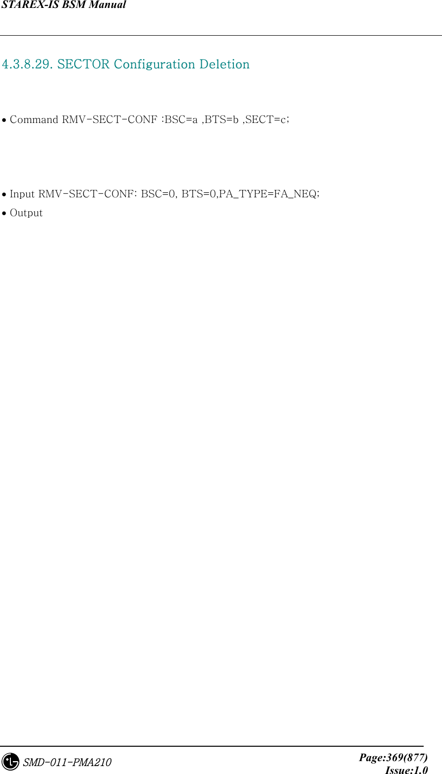
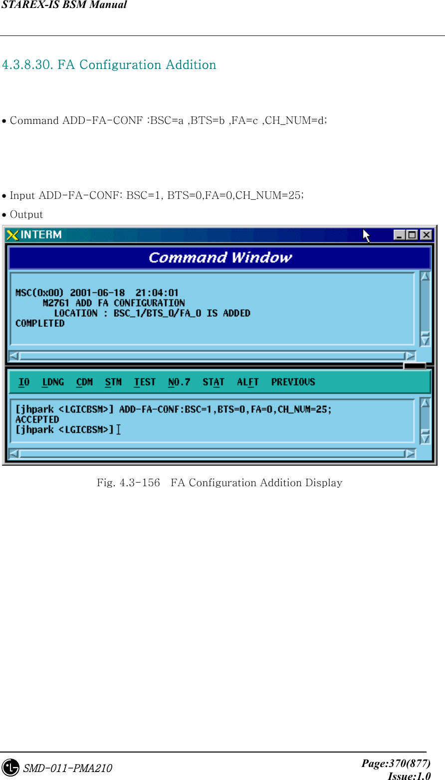
![STAREX-IS BSM Manual Page:339(877)Issue:1.0SMD-011-PMA210 4.3.8.1. BTS Configuration Information Change • Command CHG-BTS-CONF :BSC=a ,BTS=b [,PA_TYPE=c] [,ANT_TYPE=d] [,ANT_DUP=e] [,RX_DIV=f] [,LNA_EQP=g] [,RISA_EQP=h] [,BOTA_EQP=i]; • Input CHG-BTS-CONF: BSC=0, BTS=0,PA_TYPE=FA_NEQ; • Output Fig. 4.3-133 BTS Configuration Information Change Display](https://usermanual.wiki/LG-Electronics-USA/3G1XOUTBTS.Users-Manual-Part-2/User-Guide-178514-Page-22.png)
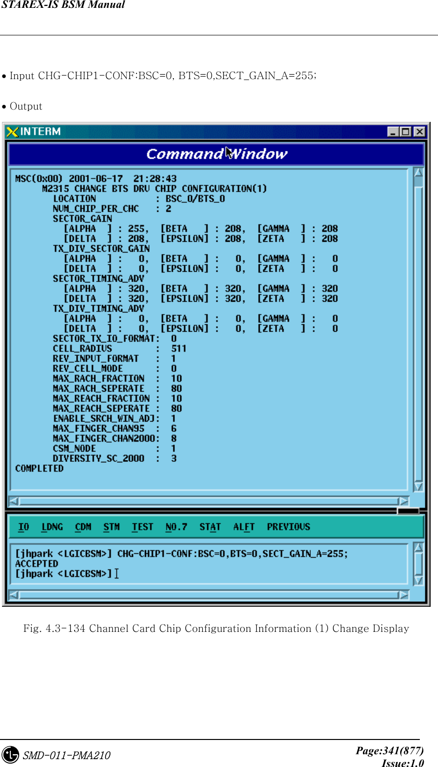
![STAREX-IS BSM Manual Page:340(877)Issue:1.0SMD-011-PMA210 4.3.8.2. Channel Card Chip Configuration Information (1) Change • Command CHG-CHIP1-CONF :BSC=a ,BTS=b [,SECT_GAIN_A=c] [,SECT_GAIN_B=d] [,SECT_GAIN_G=e] [,SECT_GAIN_D=f] [,SECT_GAIN_E=g] [,SECT_GAIN_Z=h] [,T_DIV_SECT_A=i] [,T_DIV_SECT_B=j] [,T_DIV_SECT_G=k] [,T_DIV_SECT_D=l] [,T_DIV_SECT_E=m] [,T_DIV_SECT_Z=n] [,SECT_T_ADV_A=o] [,SECT_T_ADV_B=p] [,SECT_T_ADV_G=q] [,SECT_T_ADV_D=r] [,SECT_T_ADV_E=s] [,SECT_T_ADV_Z=t] [,T_DIV_T_ADV_A=u] [,T_DIV_T_ADV_B=v] [,T_DIV_T_ADV_G=w] [,T_DIV_T_ADV_D=x] [,T_DIV_T_ADV_E=y] [,T_DIV_T_ADV_Z=z];](https://usermanual.wiki/LG-Electronics-USA/3G1XOUTBTS.Users-Manual-Part-2/User-Guide-178514-Page-23.png)
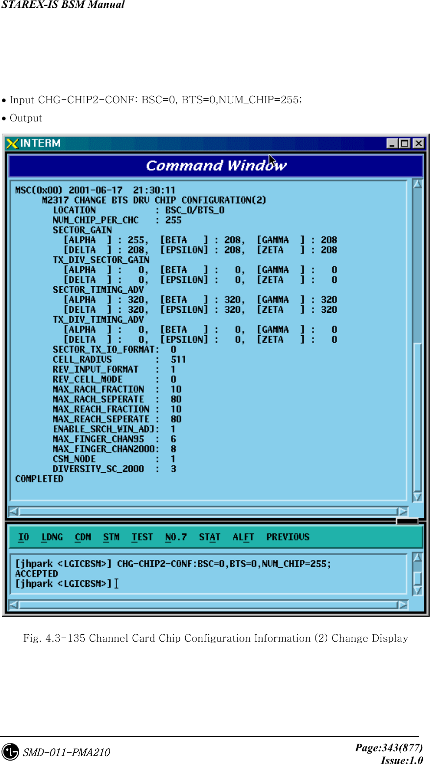
![STAREX-IS BSM Manual Page:342(877)Issue:1.0SMD-011-PMA210 4.3.8.3. Channel Card Chip Configuration Information (2) Change • Command CHG-CHIP2-CONF :BSC=a ,BTS=b [,NUM_CHIP=c] [,SECT_T_IO=d] [,CELL_RADIUS=e] [,REV_IN_FORM=f] [,R_CELL_MODE=g] [,MAX_RACH_F=h] [,MAX_RACH_S=i] [,MAX_REACH_F=j] [,MAX_REACH_S=k] [,SRCH_WIN_ADJ=l] [,MAX_CH95=m] [,MAX_CDMA2K=n] [,CSM_MODE=o] [,DIV_SCALE_2K=p];](https://usermanual.wiki/LG-Electronics-USA/3G1XOUTBTS.Users-Manual-Part-2/User-Guide-178514-Page-25.png)
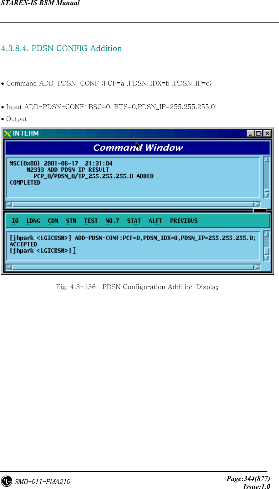
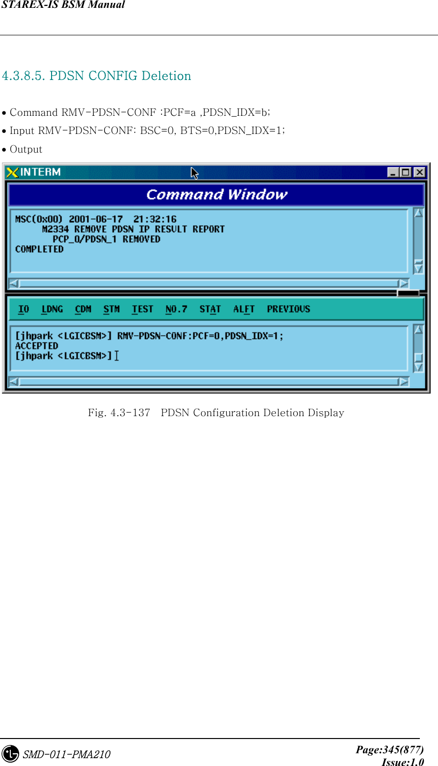
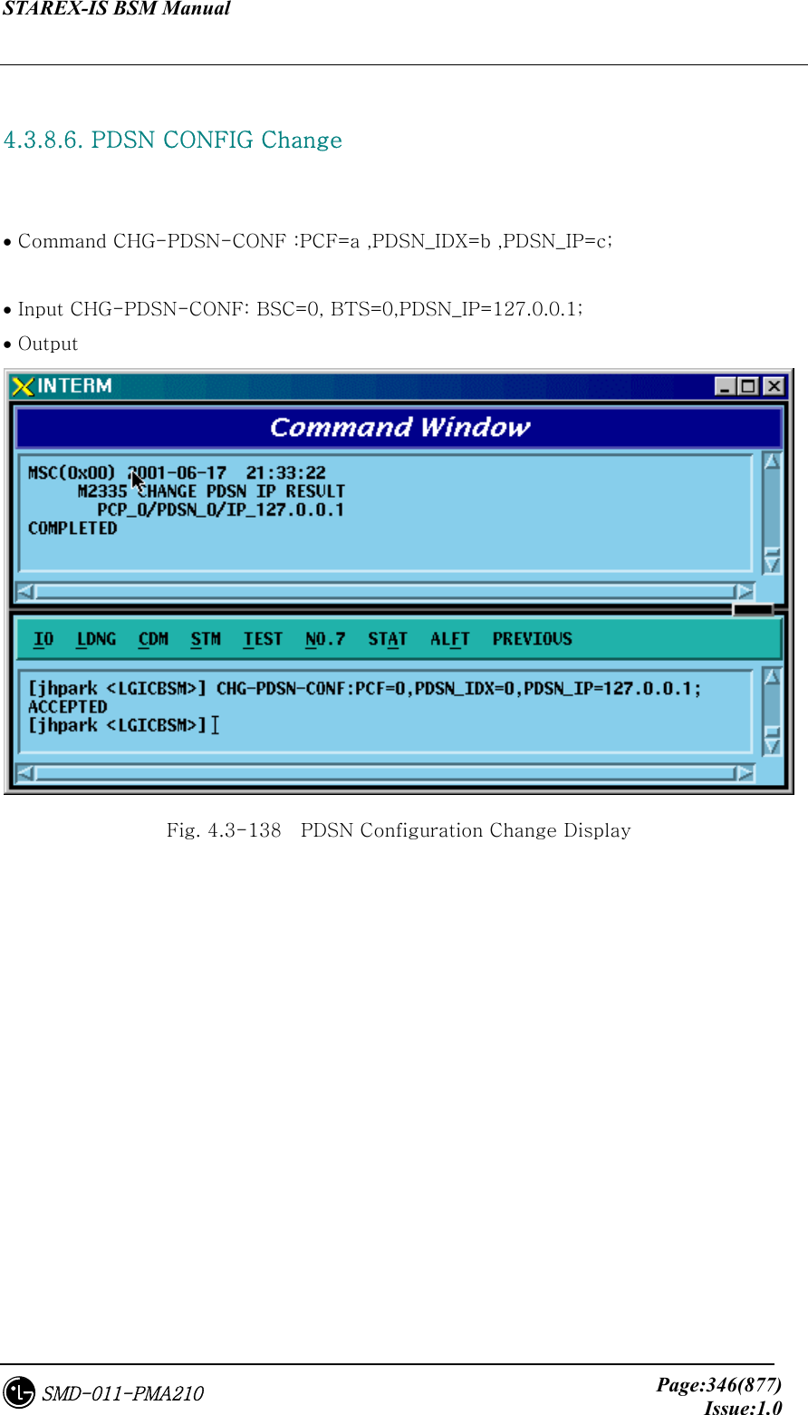
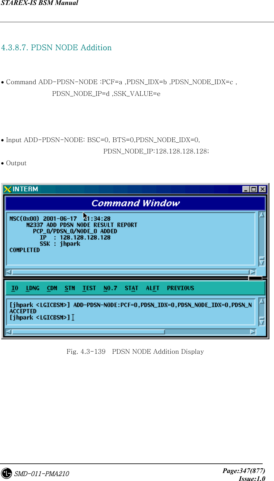
![STAREX-IS BSM Manual Page:349(877)Issue:1.0SMD-011-PMA210 4.3.8.9. PDSN NODE Change • Command CHG-PDSN-NODE :PCF=a ,PDSN_IDX=b ,PDSN_NODE_IDX=c [,PDSN_NODE_IP=d] [,SSK_VALUE=e] • Input CHG-PDSN-NODE: BSC=0, BTS=0,PDSN_IDX=0,PDSN_NODE_IDX=0, PDSN_NODE_IP=100.100.0.1, SSK_VALUE=gamdok; • Output Fig. 4.3-141 PDSN NODE Change Display](https://usermanual.wiki/LG-Electronics-USA/3G1XOUTBTS.Users-Manual-Part-2/User-Guide-178514-Page-32.png)
![STAREX-IS BSM Manual Page:366(877)Issue:1.0SMD-011-PMA210 4.3.8.26. BTS Configuration Addition • Command ADD-BTS-CONF :BSC=a ,BTS=b ,B_TYPE=c ,SECT_EQP=d ,SECT_RANGE=e ,ALMA=f ,ALPA=g ,ALPA_LINK=h ,LICA=i ,LICA_LINK=j ,FA0_CH_NUM=k ,PN_ALPHA=l [,PN_BETA=m] [,PN_GAMMA=n] [,PN_DELTA=o] [,PN_EPSILON=p] [,PN_ZETA=q] [,PA_TYPE=r] [,ANT_TYPE=s] [,LNA_TYPE=t] [,RISA_EQP=u] [,BOTA_EQP=v]; • Input Input ADD-BTS-CONF: BSC=0, BTS=0; -> ADD-BTS-CONF: BSC=1, BTS=0,B_TYPE=STANDARD,SECT_EQP=OMNI; • Output](https://usermanual.wiki/LG-Electronics-USA/3G1XOUTBTS.Users-Manual-Part-2/User-Guide-178514-Page-49.png)
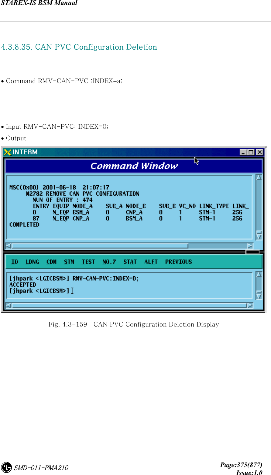
![STAREX-IS BSM Manual Page:374(877)Issue:1.0SMD-011-PMA210 4.3.8.34. CAN PVC Configuration Addition • Command ADD-CAN-PVC :NODE_A=a ,NODE_B=b ,VPCI_A=c ,VPCI_B=d [,NO_VC=e] ; • Input ADD-CAN-PVC: NODE_A=CTYPE_BSM_A, NODE_B=CTYPE_CNP_A, VPCL_A=0,VPCL_B=0; • Output Fig. 4.3-158 CAN PVC Configuration Addition Display](https://usermanual.wiki/LG-Electronics-USA/3G1XOUTBTS.Users-Manual-Part-2/User-Guide-178514-Page-57.png)
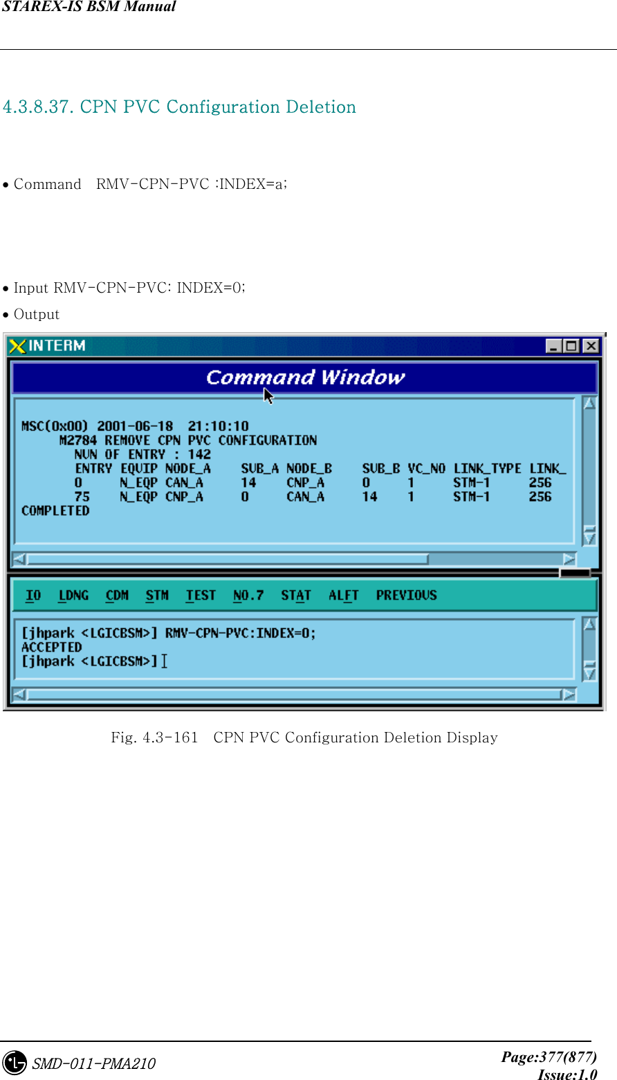
![STAREX-IS BSM Manual Page:376(877)Issue:1.0SMD-011-PMA210 4.3.8.36. CPN PVC Configuration Addition • Command ADD-CPN-PVC :NODE_A=a ,NODE_B=b ,VPCI_A=c ,VPCI_B=d [,NO_VC=e] ; • Input ADD-CPN-PVC:NODE_A=CTYPE_CAN_A, NODE_B=CTYPE_CAN_B, VPCI_A=0, VPCI_B=0; • Output Fig. 4.3-160 CPN PVC Configuration Addition Display](https://usermanual.wiki/LG-Electronics-USA/3G1XOUTBTS.Users-Manual-Part-2/User-Guide-178514-Page-59.png)
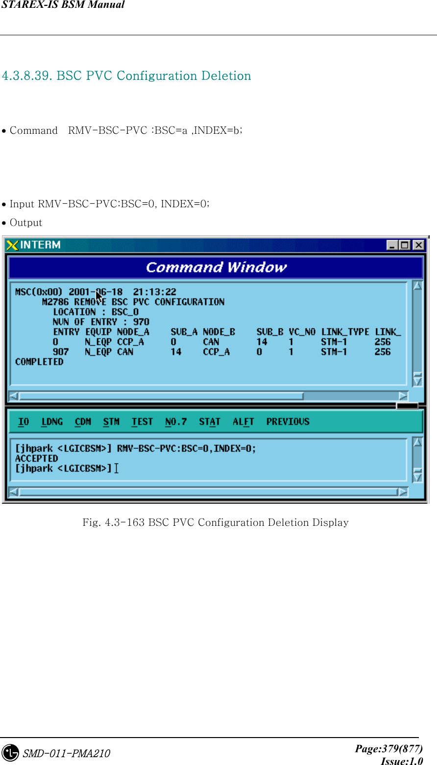
![STAREX-IS BSM Manual Page:378(877)Issue:1.0SMD-011-PMA210 4.3.8.38. BSC PVC Configuration Addition • Command ADD-BSC-PVC :BSC=a ,NODE_A=b ,NODE_B=c ,VPCI_A=d ,VPCI_B=e [,NO_VC=f]; • Input ADD-BSC-PVC:BSC=0, NODE_A=CTYPE_CCP_A, NODE_B=CTYPE_CCP_B, VPCI_A=0, VPCI_B=0; • Output Fig. 4.3-162 BSC PVC Configuration Addition Display](https://usermanual.wiki/LG-Electronics-USA/3G1XOUTBTS.Users-Manual-Part-2/User-Guide-178514-Page-61.png)
![STAREX-IS BSM Manual Page:381(877)Issue:1.0SMD-011-PMA210 4.4.1.2. BSC Processor Status Display Command Function to display Processor status inserted in BSC. Command : DIS-BSC-PRC[:BSC=a]; a : BSC Number(0~11) Input : DIS-BSC-PRC:BSC=0; Fig. 4.4-2 Result of BSC Processor Status Display 4.4.1.3. Status Display Command of BTS Processor Function to display operation status of processors mounted in all the BTSs within the corresponding BSC or in each BTS Command : DIS-BTS-STS:BSC=a[,BTS=b]; a:BSC Number (0~11) b:BTS Number (0~47) Input : DIS-BTS-STS:BSC=0,BTS=0; Output Fig. 4.4-3 Result of BTS Processor Status Display Command](https://usermanual.wiki/LG-Electronics-USA/3G1XOUTBTS.Users-Manual-Part-2/User-Guide-178514-Page-64.png)
![STAREX-IS BSM Manual Page:382(877)Issue:1.0SMD-011-PMA210 4.4.1.4. Processor Restart Command Function to restart Processors • Command : RST-PRC[:BSC=a][,BTS=b],RANGE=c,SIDE=d,CLS=e; a : BSC Number (0~11) b : BTS Number (0~47) c : Scope of restart(All the Processors of CCP, PNP,NCP,PCP., etc.) d : Side to restart (A,B,BOTH) e : Class (RESTART, REBOOT, FLASH) RESTART : Restart O/S and receive loading of PLD only. REBOOT : It executes BOOTER. In case of the processors equipped with Flash ROM, they check upper level processors and version of each block. If they are different, they receive loading from the upper level processors. However, if they are the same, they do not receive loading from the upper level processors. The processors with no Flash ROM receive loading from the upper level processors without checking version. . For reference, Active Side before and after reboot does not change. FLASH : Delete Flash content of the Processor with Flash ROM equipped and reboot it to receive loading of all the files from the upper level Processor. For reference, Active Side before and after Flash Reboot changes. Input : RST-PRC:BSC=0,BTS=0,RANGE=RCP00,SIDE=A,CLS=RESTART; Fig. 4.4-4 Result of Processor Restart Command](https://usermanual.wiki/LG-Electronics-USA/3G1XOUTBTS.Users-Manual-Part-2/User-Guide-178514-Page-65.png)
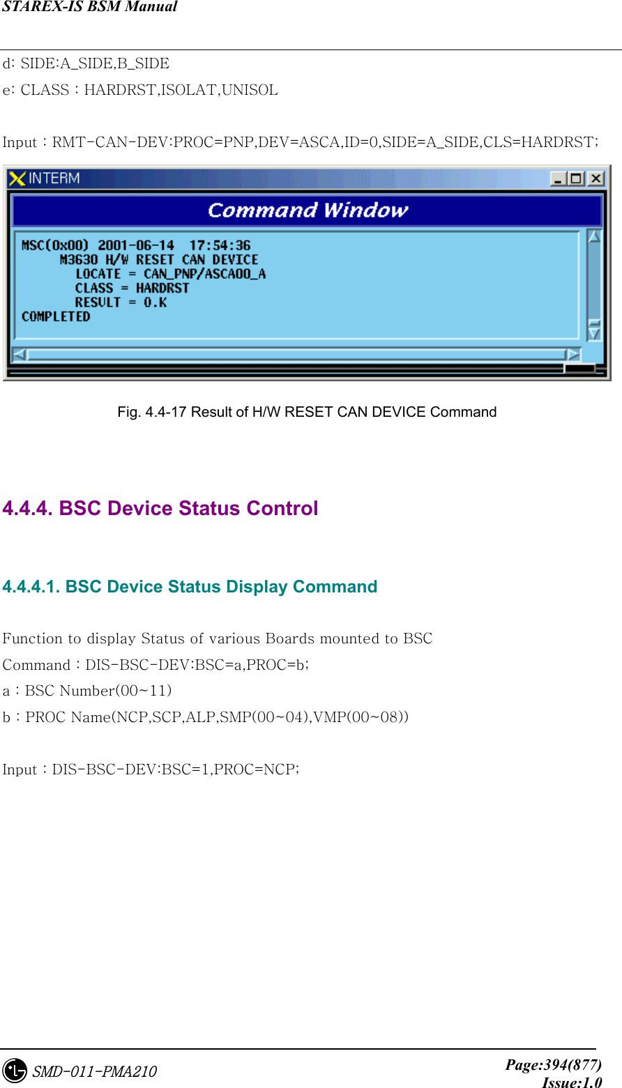
![STAREX-IS BSM Manual Page:383(877)Issue:1.0SMD-011-PMA210 4.4.1.5. CAN Processor H/W RESET(ISOLATION) COMMAND Function to reset CAN Processor H/W. Command : RMT-CAN-PRC:PROC=a,SIDE=b,CLS=c; a: Processor Name : CNP,PNP,PCP,PMP b: Side : A,B c: CLASS : HARDRST,ISOLAT,UNISOL HARDRST : Function to reset Processor on H/W Level (using Register Setting). ISOLAT : Function to isolate Processor on H/W Level (maintaining Status of RESET) UNISOL : Function to release the isolation Input : RMT-CAN-PRC:PROC=PNP,SIDE=A,CLS=ISOLAT; Fig. 4.4-5 CAN Processor H/W Command Result 4.4.1.6. BSC Processor H/W RESET(ISOLATION) COMMAND Function to reset BSC Processor H/W. Command : RMT-BSC-PRC:BSC=a,PROC=b,[SIDE=c],CLS=d; a: BSC Number b: Processor Name : CCP,NCP,SCP,ALP,SMP,VMP c: Side : A,B d: CLASS : HARDRST,ISOLAT,UNISOL HARDRST : Function to RESET Processor on H/W Level (using Register Setting). ISOLAT : Function to isolate Processor on H/W Level (RESET Status maintained) UNISOL : Function to release isolation](https://usermanual.wiki/LG-Electronics-USA/3G1XOUTBTS.Users-Manual-Part-2/User-Guide-178514-Page-66.png)
![STAREX-IS BSM Manual Page:384(877)Issue:1.0SMD-011-PMA210 Input : RMT-BSC-PRC:BSC=0,PROC=NCP,SIDE=A,CLS=ISOLAT; Fig. 4.4-6 BSC Processor H/W Command Result 4.4.1.7. BTS Processor H/W RESET(ISOLATION) COMMAND Function to BSC Processor H/W. Command : RMT-BTS-PRC:BSC=a,BTS=b,PROC=c,[SIDE=d],CLS=e; a: BSC Number b: BTS Number c: Processor Name : BSP,BPP,CRP,RCP(00~05) d: Side : A,B e: CLASS : HARDRST,ISOLAT,UNISOL HARDRST : Function to RESET Processor on H/W Level (using Register Setting). ISOLAT : Function to isolate Processor on H/W Level (RESET Status maintained) UNISOL : Function to release isolation Input : RMT-BTS-PRC:BSC=0,BTS=0,PROC=BSP,SIDE=A,CLS=ISOLAT; Fig. 4.4-7 BTS Processor H/W RESET(ISOLATION) Command Display Result](https://usermanual.wiki/LG-Electronics-USA/3G1XOUTBTS.Users-Manual-Part-2/User-Guide-178514-Page-67.png)
![STAREX-IS BSM Manual Page:385(877)Issue:1.0SMD-011-PMA210 4.4.1.8. Processor Switch Over(Switch) Command Function to Switch over Processor. Switching Over Command is executed for duplicated Processors and is performed only when both sides of Processors are in a normal status. Command : SWT-PRC [:BSC=a] [,BTS=b] ,PROC=c; a: BSC Number b: BTS Number c: Processor Name : CNP, PNP, PCP00, PCP01,PCP02, PMP00, PMP01,PMP02, CCP, NCP, SCP,ALP, BSP, CRP, RCP00, RCP01, RCP02, RCP03,RCP04, RCP05 Input : SWT-PRC :BSC=1 ,PROC=CCP; Fig. 4.4-8 Processor Switch Over(Switch) Command Display Result 4.4.2. Network Status Control Table 4.4-2 Network Node Status LIST Status Types Definition Description NORM Normal Normal Operation NOR_A Normal Act While normally operated, Act Status is maintained (Duplicated node) NOR_S Normal Standby While normally operated, Standby Status is maintained (Duplicated node)](https://usermanual.wiki/LG-Electronics-USA/3G1XOUTBTS.Users-Manual-Part-2/User-Guide-178514-Page-68.png)
![STAREX-IS BSM Manual Page:386(877)Issue:1.0SMD-011-PMA210 ABN_D Abnormal Deletion card is removed ABN_F Abnormal Fault Local Fault occurred ABN_M Abnormal MMC Block Blocked Status by User’s MMC INIT Initial Even equipped to PLD, a processor managing the corresponding device does not normally operate until now AB_OB Abnormal Online Block Based on judgment that a normal call is impossible due to faults in other devices, the corresponding device is blocked N_EQP Not Equipped Card Type is not defined in PLD 4.4.2.1. Network Status Display Command Function to display the BSS Network status. Command : DIS-NET-STS: [BSC=a],[BTS=b],SHELF=c,CARD=d,ID=e,[CHIP=f]; a : BSC Number b : BTS Number c : SHELF NAME(CAMU,CAMDU,ASMU,ALSU,BANU) d : CARD NAME(ASCA,ASIA,AOTA,ATSA,ALMA,LICA) e : CARD ID(0~3) f : CHIP Number(0~1) Input : DIS-NET-STS:BSC=0,BTS=0,SHELF=BANU,CARD=LICA,ID=0;](https://usermanual.wiki/LG-Electronics-USA/3G1XOUTBTS.Users-Manual-Part-2/User-Guide-178514-Page-69.png)
![STAREX-IS BSM Manual Page:389(877)Issue:1.0SMD-011-PMA210 4.4.2.5. ALPA Network Block Command Function to block the ALPA Network. Command : BLK-ALPA:BSC=a,ALMA=b,ALPA=c,[TYPE=d],[LINK=e]; a: BSC Number(00~11) b: ALMA ID(0~1) c: ALPA ID(0~4) d: TYPE(STM_1,E1) e: LINK(0~15) Input : BLK-ALPA:BSC=0,ALMA=0,ALPA=0,TYPE=STM_1,LINK=0; Fig. 4.4-13 Result of ALPA Network Block Command 4.4.2.6. UNBlock Command Function to unblock the ALPA Network. Command : UBLK-ALPA:BSC=a,ALMA=b,ALPA=c,[TYPE=d],[LINK=e]; a: BSC Number(00~11) b: ALMA ID(0~1) c: ALPA ID(0~4) d: TYPE(STM_1,E1) e: LINK(0~15) Input : UBLK-ALPA:BSC=0,ALMA=0,ALPA=0,TYPE=STM_1,LINK=0;](https://usermanual.wiki/LG-Electronics-USA/3G1XOUTBTS.Users-Manual-Part-2/User-Guide-178514-Page-72.png)
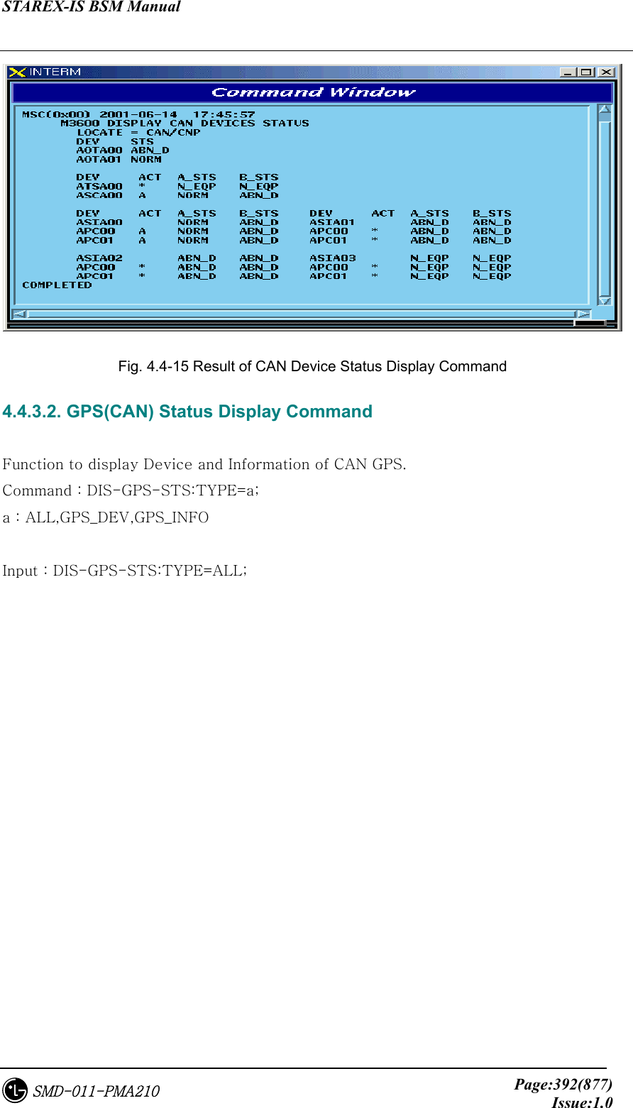
![STAREX-IS BSM Manual Page:393(877)Issue:1.0SMD-011-PMA210 Fig. 4.4-16 Result of GPS(CAN) Status Display Command 4.4.3.3. H/W RESET CAN DEVICE Command Function to reset CAN Device on H/W Level Command : RMT-CAN-DEV:PROC=a,DEV=b,ID=c,[SIDE=d],CLS=e; a: Processor :CNP,PNP,PCP(00~02),PMP(00~02) b: Device Name: ASCA,ASIA,AOTA,ATSA,PIP,FERA,FETA,BCRA c: Device ID : 0~10](https://usermanual.wiki/LG-Electronics-USA/3G1XOUTBTS.Users-Manual-Part-2/User-Guide-178514-Page-76.png)
![STAREX-IS BSM Manual Page:395(877)Issue:1.0SMD-011-PMA210 Fig. 4.4-18 Result of BSC Device Status Display 4.4.4.2. SLPA Status Display Command Function to display the SLPA Status Command : DIS-SLPA-STS:BSC=a,SMP=b,[SLPA=c]; a : BSC Number(00~11) b : SMP Number(00~04) c : SLPA Number(00~17) Input : DIS-SLPA-STS:BSC=0,SMP=0,SLPA=0; Fig. 4.4-19 Result of SLPA Status Display Command 4.4.4.3. VCPA Status Display Command Function to display the VCPA Status](https://usermanual.wiki/LG-Electronics-USA/3G1XOUTBTS.Users-Manual-Part-2/User-Guide-178514-Page-78.png)
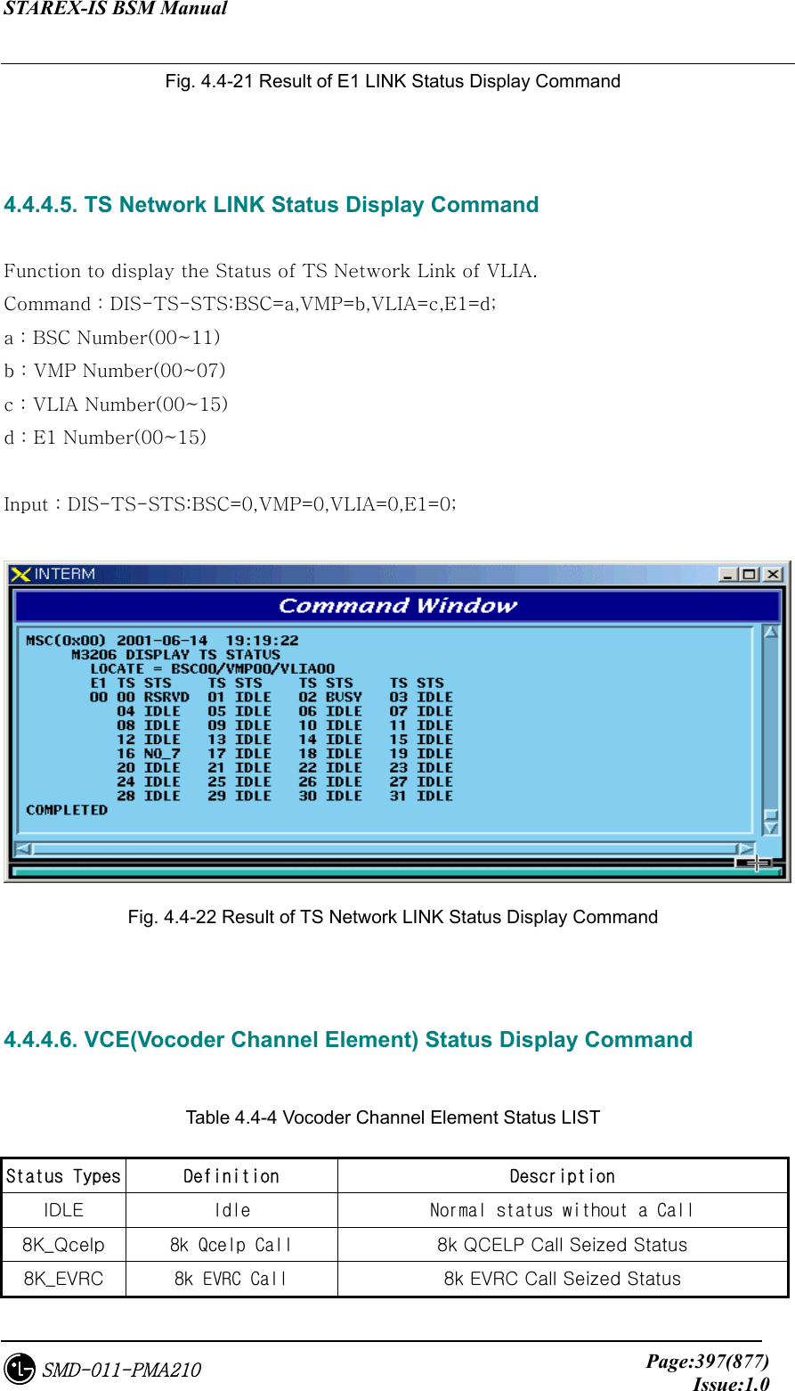
![STAREX-IS BSM Manual Page:396(877)Issue:1.0SMD-011-PMA210 Command : DIS-VCPA-STS:BSC=a,VMP=b,[VCPA=c]; a : BSC Number(00~11) b : VMP Number(00~07) c : VCPA Number(00~15) Input : DIS-VCPA-STS:BSC=0,VMP=0,VCPA=0; Fig. 4.4-20 Result of VCPA Status Display Command 4.4.4.4. E1 LINK Status Display Command Function to display E1 Link Status of VLIA Command : DIS-E1-STS:BSC=a,VMP=b,[VLIA=c]; a : BSC Number(00~11) b: VMP Number(00~07) c: VLIA Number(00~01) Input : DIS-E1-STS:BSC=0,VMP=0,VLIA=0;](https://usermanual.wiki/LG-Electronics-USA/3G1XOUTBTS.Users-Manual-Part-2/User-Guide-178514-Page-79.png)
![STAREX-IS BSM Manual Page:398(877)Issue:1.0SMD-011-PMA210 13K_Qcelp 13k Qcelp Call 13k QCELP Call Seized Status 13K_EVRC 13k EVRC Call 13k EVRC Call Seized Status ABN_M Abnormal MMC Block Blocked Status by user’s MMC UNDEF Undefined Status Status with Input of undefined Status Function to display the Channel Element Status of VCE. Command : DIS-VCE-STS:BSC=a,VMP=b,[VCPA=c]; a : BSC Number(00~11) b : VMP Number(00~07) c: VCPA Number(00~15) Input : DIS-VCE-STS:BSC=0,VMP=0,VCPA=0; Fig. 4.4-23 Result of VCE(Vocoder Channel Element) Status Display Command 4.4.4.7. SLPA BLOCK Command Function to block SLPA. Command : BLK-SLPA:BSC=a,SMP=b,SLPA=c,[SLV=d]; a : BSC Number(00~11) b : SMP Number(00~04) c : SLPA Number(00~17) d : SLV Number(00~03) Input : BLK-SLPA:BSC=0,SMP=0,SLPA=0,SLV=0;](https://usermanual.wiki/LG-Electronics-USA/3G1XOUTBTS.Users-Manual-Part-2/User-Guide-178514-Page-81.png)
![STAREX-IS BSM Manual Page:399(877)Issue:1.0SMD-011-PMA210 Fig. 4.4-24 Result of SLPA BLOCK Command 4.4.4.8. SLPA UNBLOCK Command Function to unblock SLPA. Command : UBLK-SLPA:BSC=a,SMP=b,SLPA=c,[SLV=d]; a : BSC Number(00~11) b : SMP Number(00~04) c : SLPA Number(00~17) d : SLV Number(00~03) Input : UBLK-SLPA:BSC=0,SMP=0,SLPA=0,SLV=0; Fig. 4.4-25 Result of SLPA UNBLOCK Command 4.4.4.9. VCPA BLOCK Command Function to block VCPA. Command : BLK-VCPA:BSC=a,VMP=b,VCPA=c,[SLV=d],[DSP=e]; a : BSC Number(00~11)](https://usermanual.wiki/LG-Electronics-USA/3G1XOUTBTS.Users-Manual-Part-2/User-Guide-178514-Page-82.png)
![STAREX-IS BSM Manual Page:400(877)Issue:1.0SMD-011-PMA210 b : VMP Number(00~07) c : VCPA Number(00~15) d : SLV Number(00~01) e : DSP Number(00~03) Input : BLK-VCPA:BSC=0,VMP=0,VCPA=0,SLV=0,DSP=0; Fig. 4.4-26 Result of VCPA BLOCK Command 4.4.4.10. VCPA UNBLOCK Command Function to unblock VCPA Command : UBLK-VCPA:BSC=a,VMP=b,VCPA=c,[SLV=d],[DSP=e]; a : BSC Number(00~11) b : VMP Number(00~07) c : VCPA Number(00~15) d : SLV Number(00~01) e : DSP Number(00~03) Input : UBLK-VCPA:BSC=0,VMP=0,VCPA=0,SLV=0,DSP=0;](https://usermanual.wiki/LG-Electronics-USA/3G1XOUTBTS.Users-Manual-Part-2/User-Guide-178514-Page-83.png)
![STAREX-IS BSM Manual Page:401(877)Issue:1.0SMD-011-PMA210 Fig. 4.4-27 Result of VCPA UNBLOCK Command 4.4.4.11. VLIA BLOCK Command Function to block VLIA. Command : BLK-VLIA:BSC=0,VMP=0,VLIA=0,[E1=0],[TS=1]; a : BSC Number(00~11) b : VMP Number(00~07) c : VLIA Number(0~1) d : E1 Number(00~15) e : TS Number(00~31) Input : BLK-VLIA:BSC=0,VMP=0,VLIA=0,E1=0,TS=1; Fig. 4.4-28 Result of VLIA BLOCK Command 4.4.4.12. VLIA UNBLOCK Command Function to unblock VLIA Command : UBLK-VLIA:BSC=0,VMP=0,VLIA=0,[E1=0],[TS=1]; a : BSC Number(00~11) b : VMP Number(00~07)](https://usermanual.wiki/LG-Electronics-USA/3G1XOUTBTS.Users-Manual-Part-2/User-Guide-178514-Page-84.png)
![STAREX-IS BSM Manual Page:402(877)Issue:1.0SMD-011-PMA210 c : VLIA Number(0~1) d : E1 Number(00~15) e : TS Number(00~31) Input : UBLK-VLIA:BSC=0,VMP=0,VLIA=0,E1=0,TS=1; Fig. 4.4-29 Result of VLIA UNBLOCK Command 4.4.4.13. H/W RESET BSC Device Command Function to reset BSC Device on H/W Level. Command : RMT-BSC-DEV:BSC=a,PROC=b,DEV=c,ID=d,[SUBID=e],CLS=f; a : BSC Number(00~11) b : Processor Name(NCP,SCP,ALP,SMP(00~05),VMP(00~07)) c : Device Name(SLPA,VCPA,VLIA,STIA,ASCA,ASIA,AOTA,ATSA,ALMA) d : Device ID(00~17) e : Sub_id(A_SIDE,B_SIDE) f : Class(HARDRST,ISOLAT,UNISOL) Input : RMT-BSC-DEV:BSC=0,PROC=SMP00,DEV=SLPA,ID=0,CLS=HARDRST;](https://usermanual.wiki/LG-Electronics-USA/3G1XOUTBTS.Users-Manual-Part-2/User-Guide-178514-Page-85.png)
![STAREX-IS BSM Manual Page:405(877)Issue:1.0SMD-011-PMA210 Fig. 4.4-33 Result of FA Status Display Command 4.4.5.3. BLOCK DBPA Command Function to block DBPA. Command : BLK-DBPA:BSC=a,BTS=b,RCP=c,DBPA=d,[CHIP=e],[CONDITION=f]; a : BSC Number(00~11) b : BTS Number(00~47) c : RCP Number(0~5)](https://usermanual.wiki/LG-Electronics-USA/3G1XOUTBTS.Users-Manual-Part-2/User-Guide-178514-Page-88.png)
![STAREX-IS BSM Manual Page:406(877)Issue:1.0SMD-011-PMA210 d : DBPA Number(0~9) e : CHIP Number(0~1) f : Select Option(conditional, unconditional) Conditional : If there is call connected, wait until it is disconnected during timeout and then block it. If it is not disconnected until timeout, do not block it. Unconditional : block a call regardless of their presence unconditionally. (The existing call is disconnected) Reference : If an OverHead Channel is allocated, do not block a call unconditionally. Input : BLK-DBPA:BSC=0,BTS=0,RCP=0,DBPA=1,CHIP=1,CONDITION=CONDITION; Fig. 4.4-34 Result of BLOCK DBPA Command 4.4.5.4. UNBLOCK DBPA Command Function to unblock DBPA Command : UBLK-DBPA:BSC=a,BTS=b,RCP=c,DBPA=d,[CHIP=e],[CONDITION=f]; a : BSC Number(00~11) b : BTS Number(00~47) c : RCP Number(0~5) d : DBPA Number(0~9) e : CHIP Number(0~1) Input : UBLK-DBPA:BSC=0,BTS=0,RCP=0,DBPA=1,CHIP=1;](https://usermanual.wiki/LG-Electronics-USA/3G1XOUTBTS.Users-Manual-Part-2/User-Guide-178514-Page-89.png)
![STAREX-IS BSM Manual Page:408(877)Issue:1.0SMD-011-PMA210 Command : UBLK-OVHD-CE:BSC=a,BTS=b,SECTOR=c,FA=d; a : BSC Number(00~11) b : BTS Number(00~47) c : SECTOR(ALPHA,BETA,GAMMA,DELTA,EPSILON,ZETA) d : FA Number(0~5) Input : UBLK-OVHD-CE:BSC=0,BTS=0,SECTOR=ALPHA,FA=0; Fig. 4.4-37 Result of UNBLOCK OverHead Channel Element 4.4.5.7. H/W RESET BTS Device Command Function to reset BTS Device on H/W.Level Command : RMT-BTS-DEV:BSC=a,BTS=b,PROC=c,DEV=d,[ID=e],CLS=f; a : BSC Number(00~11) b : BTS Number(00~47) c : Processor Name(BSP,BPP,CRP,RCP(00~05) d : Device Name(ARIA,DBPA,BUDA,HPA,PACA,BADA,RISA,BOTA,LICA) e : Device ID(0~9) f : Class(HARDRST,ISOLAT,UNISOL) Input : RMT-BTS-DEV:BSC=0,BTS=0,PROC=CRP,DEV=LICA,ID=0,CLS=HARDRST;](https://usermanual.wiki/LG-Electronics-USA/3G1XOUTBTS.Users-Manual-Part-2/User-Guide-178514-Page-91.png)

![STAREX-IS BSM Manual Page:414(877)Issue:1.0SMD-011-PMA210 4.4.6.3. Allow Inhibited Message Command Function to allow display of Status Message whose display to Outterm is inhibited Command : ALW-STS-MSG:SN=a; a: SN Number(ALL,S3002~S3020, S3201~S3230, S3501,S3502) Input : ALW-STS-MSG:SN=S3002; Fig. 4.4-44 Result of Inhibited Message Display Allow Command 4.4.7. Overload Status Control 4.4.7.1. Processor Overload Status Display Command Function to display processor Overload Status Command : DIS-OVLD-STS:[BSC=a],[BTS=b],PROC=c; a : BSC Number(00~11) b : BTS Number(00~47) c : Processor Name(CCP,BSP) Input : DIS-OVLD-STS:BSC=0,BTS=0,PROC=BSP;](https://usermanual.wiki/LG-Electronics-USA/3G1XOUTBTS.Users-Manual-Part-2/User-Guide-178514-Page-97.png)
![STAREX-IS BSM Manual Page:415(877)Issue:1.0SMD-011-PMA210 Fig. 4.4-45 Result of Processor Overload Status Display Command 4.4.7.2. Overload Threshold Value Display Command Function to display Overload Threshold Value Command : DIS-OVLD-THR:BSC=a,[BTS=b],PROC=c; a : BSC Number(00~11) b : BTS Number(00~47) c : Processor Name(CCP,BSP) Input : DIS-OVLD-THR:BSC=0,BTS=0,PROC=BSP;](https://usermanual.wiki/LG-Electronics-USA/3G1XOUTBTS.Users-Manual-Part-2/User-Guide-178514-Page-98.png)
![STAREX-IS BSM Manual Page:416(877)Issue:1.0SMD-011-PMA210 Fig. 4.4-46 Result of Overload Threshold Value Display Command 4.4.7.3. Overload Threshold Value Change Command Function to change Overload Threshold Value. Command: CHG-OVLD-THR:BSC:a,[BTS=b],LEVEL=c,[LOAD=d], [ORG_PER=e],[TER_PER=f]; a : BSC Number(00~11) b : BTS Number(00~47) c : LEVEL(0~100) d : LOAD(0~100) e : ORG_PER(0~100) f : TER_PER(0~100) Input : CHG-OVLD-THR:BSC:0,BTS=0,LEVEL=0,LOAD=100, ORG_PER=97,TER_PER=100;](https://usermanual.wiki/LG-Electronics-USA/3G1XOUTBTS.Users-Manual-Part-2/User-Guide-178514-Page-99.png)
![STAREX-IS BSM Manual Page:417(877)Issue:1.0SMD-011-PMA210 Fig. 4.4-47 Result of Overload Threshold Value Change Command 4.4.7.4. Overload Generation Test Command Function to generate Overload threshold value Command : STRT-OVLD-GEN:BSC=a,[BTS=b],PROC=c,LEVEL=d; a : BSC Number(00~11) b : BTS Number(00~47) c: Processor Name(CCP,BSP) d: LEVEL(0~24) Input : STRT-OVLD-GEN:BSC=0,BTS=0,PROC=BSP,LEVEL=0; Fig. 4.4-48 Result of Overload Generation Test Command 4.4.7.5. Overload Generation Test STOP Command](https://usermanual.wiki/LG-Electronics-USA/3G1XOUTBTS.Users-Manual-Part-2/User-Guide-178514-Page-100.png)
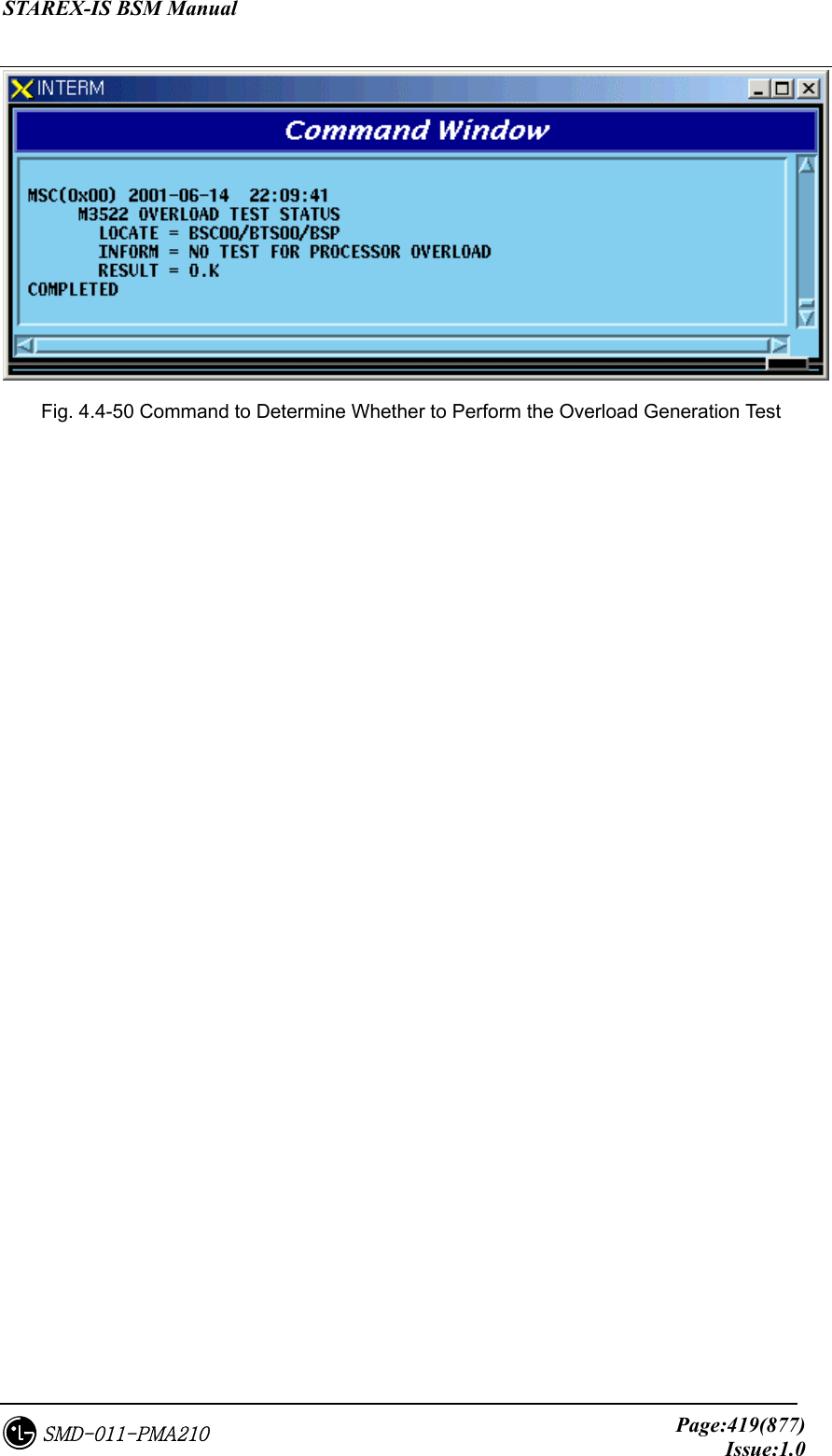
![STAREX-IS BSM Manual Page:418(877)Issue:1.0SMD-011-PMA210 Function to stop the Overload Generation Test Command : STOP-OVLD-GEN:BSC=a,[BTS=b],PROC=c,LEVEL=d; a : BSC Number(00~11) b : BTS Number(00~47) c: Processor Name(CCP,BSP) d: LEVEL(0~24) Input : STOP-OVLD-GEN:BSC=0,BTS=0,PROC=BSP,LEVEL=0; Fig. 4.4-49 Result of Overload Generation Test STOP Command 4.4.7.6. Command to Display Whether or not the Overload Generation Test is performed Function to find out whether the Overload Display Test is performed Command : DIS-OVLD-GEN:BSC=a,[BTS=b],PROC=c,LEVEL=d; a : BSC Number(00~11) b : BTS Number(00~47) c: Processor Name(CCP,BSP) d: LEVEL(0~24) Input : DIS-OVLD-GEN:BSC=0,BTS=0,PROC=BSP,LEVEL=0;](https://usermanual.wiki/LG-Electronics-USA/3G1XOUTBTS.Users-Manual-Part-2/User-Guide-178514-Page-101.png)
![STAREX-IS BSM Manual Page:420(877)Issue:1.0SMD-011-PMA210 4.5. Test Command 4.5.1. On-Line Test-related Command On-Line Test is a function that allows a test to be performed automatically at a specific time on a specific day and includes the following: Vocoder, CE, BTS Markov test and VSWR test. The tests of CE, BTS Markov and VSWR find out presence of faults in hardware of Channel Elements in BTS and the test function for radio environment, and the Vocoder test finds out presence of faults in hardware of Vocoder in BSC. Because the tests of CE, Vocoder, BTS Markov, and VSWR seize call resources, the user designates the specific time (idlest time) during the time that only a test is allowed. The tests of CE, BTS Markov, and VSWR are conducted under the supervision of BSP while the Vocoder test is conducted under the supervision of CCP. If the user designates the day and start/ending time for the Online test, and the ID scope of the board to be tested, BSM becomes the designated time of the designated day and if the test is in the ALLOW status, it commands the corresponding Processor to start/end the test. The performance of the On-Line test is decided by Command INH-ONL-TEST (Inhibit Test), ALW-ONL-TEST(Allow Test). Only when the status is designated as “ALLOW” by ALW-ONL-TEST Command, On-Line test is performed. The Command of INH-ONL-TEST inhibits the test. Besides these two Commands, there is a command to stop the test by each Test(CE : STS-CE-ONL, Vocoder : STS-VCE-ONL, BTS Markov : STS-MKV-ONL, VSWR : STS-VSWR-ONL). If the test was stopped by INHIBIT Command, the On-Line Test is not performed even if the designated time of the designated day of the week arrives because inhibit/allow status is changed to “INHIBIT”. ,. However, if the Test was stopped by the above listed STOP Command, the On-Line Test that was performed on that day only comes to a halt and at the designated time of the next designated day of the week the On-Line Test is to be performed normally because DB Flag that indicates the status of INHIBIT/ALLOW is not changed . 4.5.1.1. On-Line Test Inhibit Command It is the function that inhibits On Line Test for CE, Vocoder, BTS Markov, and VSWR test. In the cases of CE, BTS Markov, and VSWR test, input the corresponding BTS number and in the case of Vocoder test, input the corresponding BSC number. • Command INH-ONL-TEST:EXE=a, BSC=b,[BTS=c]; a: VCE/CE/MKV/VSWR](https://usermanual.wiki/LG-Electronics-USA/3G1XOUTBTS.Users-Manual-Part-2/User-Guide-178514-Page-103.png)
![STAREX-IS BSM Manual Page:421(877)Issue:1.0SMD-011-PMA210 b: BSC number (0~11) c: BTS number (0~47) • Input/Output Fig. 4.5-1 Result of Test Inhibit Command Execution 4.5.1.2. On-Line Test Allow Command Function that allows Online Test for CE, Vocoder, BTS Markov, and VSWR test For CE, BTS Markov and VSWR test, input the corresponding BTS number and for Vocoder test, input corresponding BSC number. • Command ALW-ONL-TEST:EXE=a,BSC=b[BTS=c]; a: VCE/CE/MKV/VSWR b: BSC number (0~11) c: BTS number (0~47) • Input/Output](https://usermanual.wiki/LG-Electronics-USA/3G1XOUTBTS.Users-Manual-Part-2/User-Guide-178514-Page-104.png)
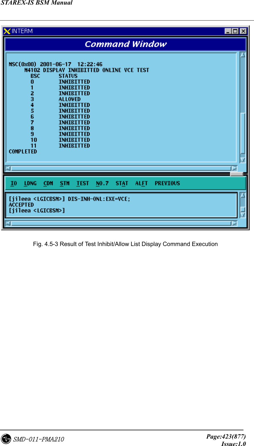
![STAREX-IS BSM Manual Page:422(877)Issue:1.0SMD-011-PMA210 Fig. 4.5-2 Result of Test Allow Command Execution 4.5.1.3. On-Line Test Inhibit Item Display Function Function to display the inhibit of the on line test for the specific tests among the on-line tests by BSC and BTS. For Vocoder test, it displays Inhibit status. In case of CE, BTS Markov and in case of the VSWR test, it displays the status by BTS. • Command DIS-INH-ONL:EXE=a,BSC=b[BTS=c]; a: VCE/CE/MKV/VSWR b: BSC number (0~11) c: BTS number (0~47) • Input/Output](https://usermanual.wiki/LG-Electronics-USA/3G1XOUTBTS.Users-Manual-Part-2/User-Guide-178514-Page-105.png)
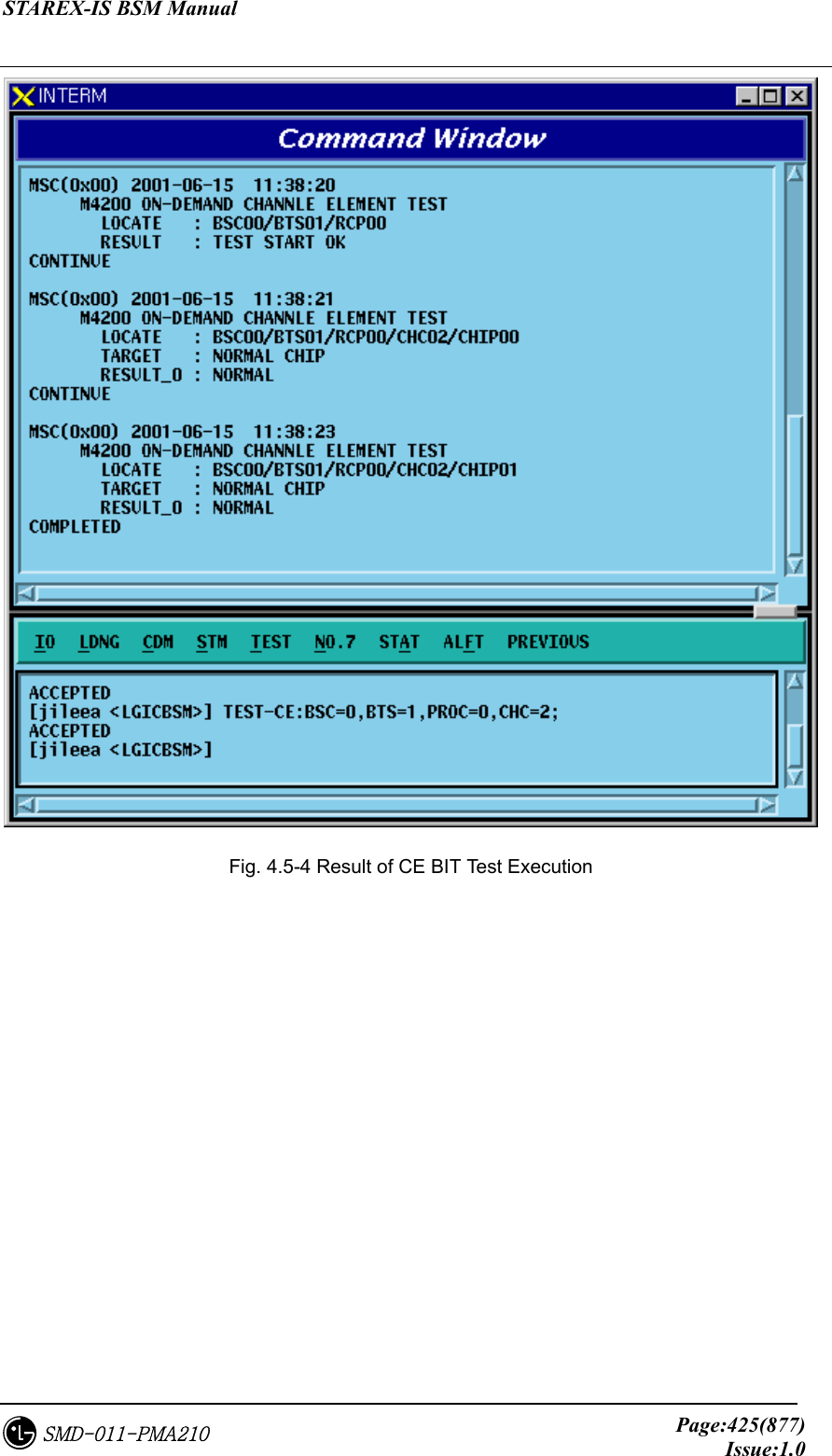
![STAREX-IS BSM Manual Page:424(877)Issue:1.0SMD-011-PMA210 4.5.2. Test-related to Channel Element Channel Element Test is performed in BIT(Built In Test) for each chip. The types of BIT Test are as follows: - Bus Interrupt Test - ChipX16 Test - PP2S Test - PCG Test This BIT Test is normally performed on Chip with OVHD channel and Chip seized with a call and the result is reported to BSM. Table 4.5-1CE Test Result Message On-Demand DESCRIPTION BIT_OK BIT_BUS_FAIL BIT_INT_FAIL BIT_CHIPX16_FAIL BIT_PP2S_FAIL BIT_PCG_FAIL BIT_RAM_FAIL BIT_PROGRESS_FAIL NORMAL BUS INTERFACE TEST FAIL INTERNAL INTERRUPT TEST FAIL CHIPX16 TEST FAIL PCG TEST FAIL MEMORY TEST FAIL TEST PERFORMING FAIL 4.5.2.1. Channel Element Test Function Function to perform BIT test by CHC and CHIP unit. • Command TEST-CE :BSC=a ,BTS=b ,PROC=c [,CHC=d] [,CHIP=e]; a: BSC number (0~11) b: BTS number (0~47) c: RCP number (0~9) d: Channel Card Number (0~9) e: Chip Number (0~1) • Input/Output](https://usermanual.wiki/LG-Electronics-USA/3G1XOUTBTS.Users-Manual-Part-2/User-Guide-178514-Page-107.png)
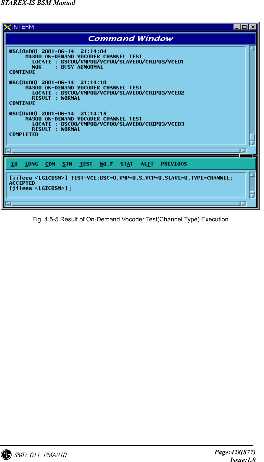
![STAREX-IS BSM Manual Page:427(877)Issue:1.0SMD-011-PMA210 FLT_DSP_HW FLT_CLK FLT_VCPA_LOOPBACK FLT_VCMA_LOOPBACK FLT_VLIA_LOOPBACK FLT_QCELP_ST0 FLT_QCELP_ST1 FLT_QCELP_ST2 FLT_QCELP_ST3 DSP HW test Fault Timing Module test Fault Vocoder Processor Loopback test Fault Vocoder Master board Loopback test Fault Vocoder Line interface Loopback test Fault Qcelp Algorithm test Fault state0 Qcelp Algorithm test Fault state1 Qcelp Algorithm test Fault state2 Qcelp Algorithm test Fault state3 4.5.3.1. On-Demand Vocoder Test Function Function to test Vocoder DSP or Channel by VCP/SLAVE/CHIP unit. • Command TEST-VCE: BSC=a ,VMP=b ,S_VCP=c [,E_VCP=d] [,SLAVE=e] [,CHIP=f] [,VCE=g] ,TYPE=h [,OPTION=i] [,WAIT_T=j] a: BSC number (0~11) b: VMP number (0~7) c, d: VCP number (0~15) e: SLAVE number (0~1) f : CHIP number (0 ~ 3) h: Test Type(DSP, Channel) i: Test Option(SKIP, RELEASE, WAIT_THEN) => These are options used to test channels when a call is seized, and SKIP does not perform a test when a call is seized but skips. With option RELEASE, it disconnects a call when a call is seized and then performs a test. With option WAIT_THEN, it waits as long as j time is allowed and if a call is released within the designated time, then it goes on with a test. However, if a call is not released, it skips. J: Wait Time(5~300 sec) • Input/Output](https://usermanual.wiki/LG-Electronics-USA/3G1XOUTBTS.Users-Manual-Part-2/User-Guide-178514-Page-110.png)
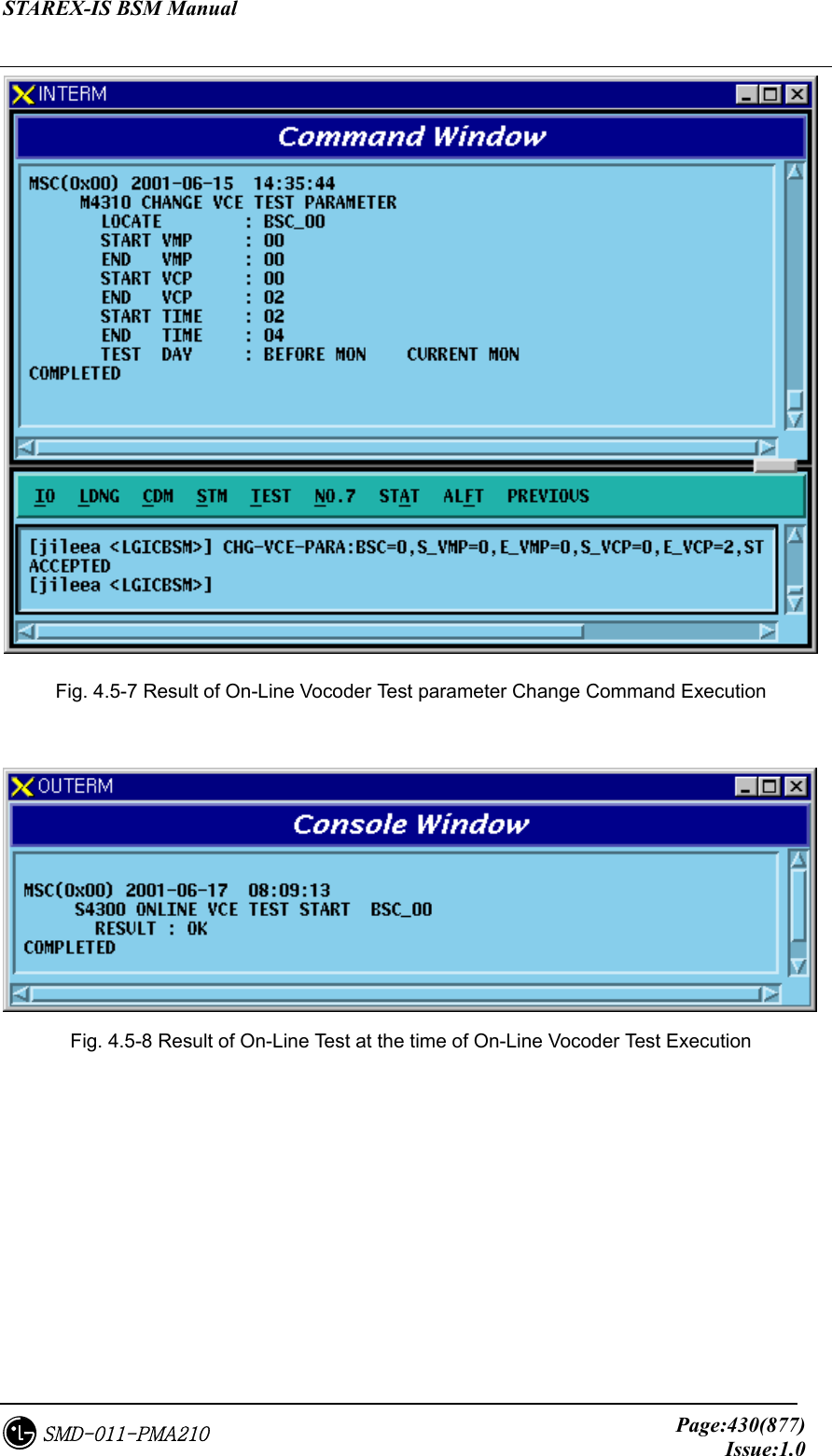
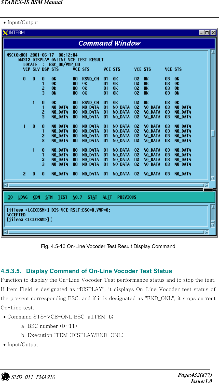
![STAREX-IS BSM Manual Page:429(877)Issue:1.0SMD-011-PMA210 Fig. 4.5-6 Result of On-Demand Vocoder Test(DSP Type) Execution 4.5.3.2. Parameter Change Command Related to On-Line Vocoder Test Function to change On-Line Vocoder test start/ending time, test day and the scope of VMP/VCP to be tested. • Command CHG-VCE-PARA :BSC=a ,S_VMP=b [,E_VMP=c] ,S_VCP=d [,E_VCP=e] [,STI ME=f] [,ETIME=g] ,WDAY=h; a: BSC number (0~11) b,c: VMP number(0~7) d,e: VCP number(0~15) f: On-Line test Start Time (0~23 Hour) g: On-Line test End Time (1~24 Hour) h: Test Day(Month ~ Day, Daily) • Input/Output](https://usermanual.wiki/LG-Electronics-USA/3G1XOUTBTS.Users-Manual-Part-2/User-Guide-178514-Page-112.png)
![STAREX-IS BSM Manual Page:434(877)Issue:1.0SMD-011-PMA210 4.5.4. Link Test Function Link test is divided into PING test, IPC test, ATM Path test, and Trunk BER test. PING test checks the Link status of Application Level by using Ping command from Master Processor to each Target Processor. IPC test checks the presence of problems in LINK by conducting IPC Test to the mounted processors/devices. ATM Path test checks presence of faults in ATM LINK Level by conducting ATM Layer Test on the mounted Processor/Devices. Trunk BER test sends/receives the designated number of ATM Cells to the operator designated BTS Link to get Error Rate. 4.5.4.1. Trunk BER Test Function Function to check the presence of problems in Trunk(16 E1) Link between BTS and BSC. Trunk BER Test analyzes performance per Link of each ALPA and LICA and the analyzed result is displayed in a certain format to BMS. One link is selected and while exchanging as many as the designated number of ATM Cells, test is conducted and Data Error Rate is displayed. • Command TEST-LINK :BSC=a ,ALPA=b [,CNT=c] [,RATE=d]; a: BSC number (0~11) b: ALPA number(0~9) c: Send Cell Count(1 ~ 1,000,000) d: Data Rate(1 ~ 90: Number of Cells transferred per a second) • Input/Output](https://usermanual.wiki/LG-Electronics-USA/3G1XOUTBTS.Users-Manual-Part-2/User-Guide-178514-Page-117.png)
![STAREX-IS BSM Manual Page:435(877)Issue:1.0SMD-011-PMA210 Fig. 4.5-12 Result of Trunk BER Test Performance 4.5.4.2. PING Test Function Function to check Link Status for the Target Processor by the Master Processor that was input to MMI of BSM by using the Ping command Ping test is divided into Point To Point Test and Point To Multi Test. • Command TEST-PING:SRC=a,DST=b[,BSC=c][,BTS=d][,SMP=e][,VMP=f][,PCF=g]; a: Source Processor b: Destination Processor(If there is input, it is PTP, if not, it is PTM) c: BSC number(0~11) d: BTS number(0~47)](https://usermanual.wiki/LG-Electronics-USA/3G1XOUTBTS.Users-Manual-Part-2/User-Guide-178514-Page-118.png)
![STAREX-IS BSM Manual Page:436(877)Issue:1.0SMD-011-PMA210 e: SMP number(0~5) f: VMP number(0~7) g: PCF number(0~2) • Input/Output Fig. 4.5-13 Result of PING Test Performance 4.5.4.3. IPC Test Function Function to check the presence of problems in the Link status between Processor/Device by executing IPC command of Application Level . IPC Test is divided into PTP test and PTM test. • Command TEST-IPC :SRC=a [,DST=b] [,BSC=c] [,BTS=d] [,SMP=e] [,VMP=f] [,PCF=g]; a: Source Processor b: Destination Processor(If input does exist, it is PTP and if not, it is PTM) c: BSC number(0~11) d: BTS number(0~47)](https://usermanual.wiki/LG-Electronics-USA/3G1XOUTBTS.Users-Manual-Part-2/User-Guide-178514-Page-119.png)
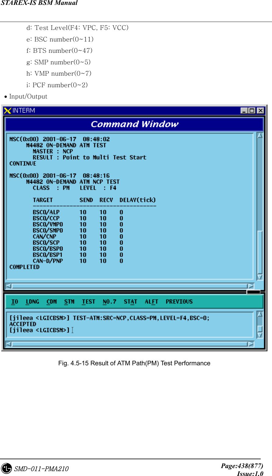
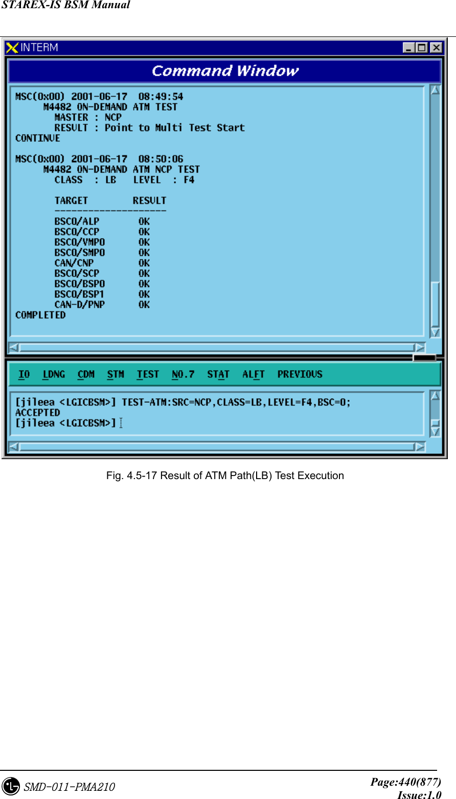
![STAREX-IS BSM Manual Page:437(877)Issue:1.0SMD-011-PMA210 e: SMP number(0~5) f: VMP number(0~7) g: PCF number(0~2) • Input/Output Fig. 4.5-14 Result of IPC Test Performance 4.5.4.4. ATM Path Test Function Function to check presence of problems in Link Status between Processor and Device by executing ATM CC, LB, PM command. It is divided into PTP Test and PTM Test. • Command TEST-TM:SRC=a[,DST=b],CLASS=c,LEVEL=d[,BSC=e][,BTS=f][,SMP=g] [,VMP=h] [,PCF=i]; a: Source Processor b: Destination Processor(If input does exist, it is PTP, and if not, it is PTM) c: Test class(CC: Continuity Check, LB: Loop Back, PM: Execution Monitor)](https://usermanual.wiki/LG-Electronics-USA/3G1XOUTBTS.Users-Manual-Part-2/User-Guide-178514-Page-120.png)

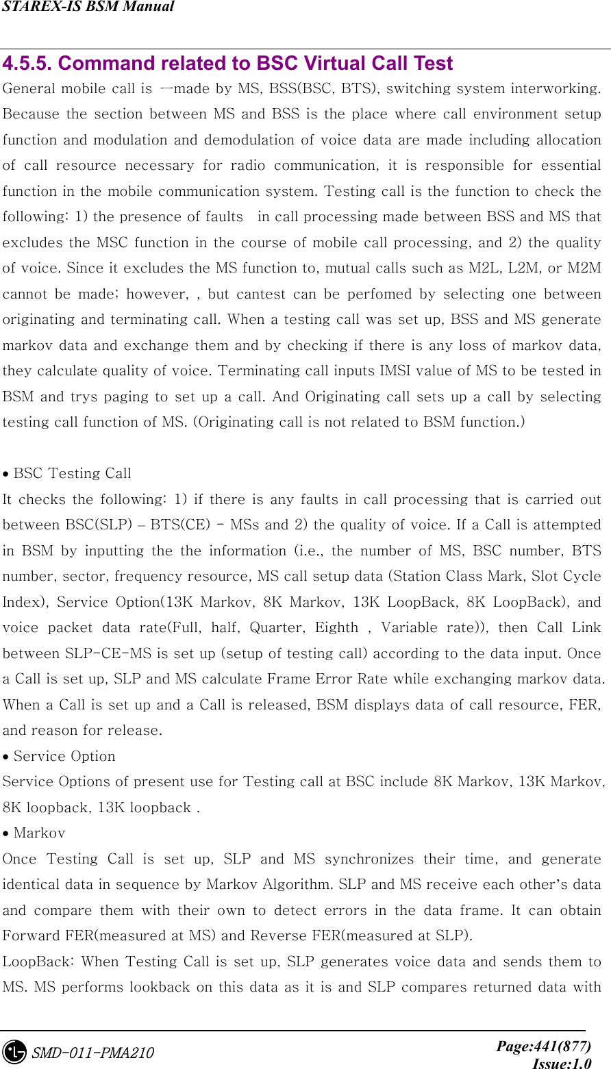
![STAREX-IS BSM Manual Page:442(877)Issue:1.0SMD-011-PMA210 the original data to validate the quality of voice. (FER measured at SLP) • Data Rate User can designate voice data rate to be used for testing call. The data rate is divided into the following: Full rate, Half rate, Quarter rate, Eighth rate, and Variable rate. 4.5.5.1. BSC Virtual Call Setup Function Function to designate various options and setting up Call to a specific MS or all the MSs MS to be tested should be entered to BSM DB with INS-TEST-MS command. When TEST_KEY is not input, testing calls are set up for all the MSs stored in DB. Testing Call is attempted for 60 minutes at a maximum. Once a Call is set up, it is maintained for 60 minutes. If a call is disconnected due to the occurrence of faults, or when a user released the call at random, a message for the reason of call release is displayed. • Command SET-TEST-CALL :BSC=a ,BTS=b ,SECTOR=c ,CDMA=d ,SCI=e ,SCM=f , OPTI=g ,DTYPE=h ,TIME=i [,TEST_KEY=j]; a: BSC number (0~11) b: BTS number (0~47) c: sector (ALPHA/BETA/GAMMA/DELTA/ZETA/EPSILON) d: CDMA number (0~11) e: SLOT CYCLE Index (0~7) f: SLOT mode (SLOT_M, NON_SLT_M) g: option (MKV_13K/MKV_8K/LB_13K/LB_8K) h: Data Rate (VARIABLE/FULL/HALF/QUART/EIGHT ) i: TIME(1~60min) j: Test Key(1 ~ 100) • Input/Output](https://usermanual.wiki/LG-Electronics-USA/3G1XOUTBTS.Users-Manual-Part-2/User-Guide-178514-Page-125.png)
![STAREX-IS BSM Manual Page:444(877)Issue:1.0SMD-011-PMA210 Fig. 4.5-20 Display at the Termination of BSC Virtual Call 4.5.5.2. Virtual Call Release Function Function to release a call for a specific MS or all the MSs where a virtual call set up. The output resulting from virtual call release is displayed by "Release by MMC". • Command REL-TEST-CALL :BSC=a ,BTS=b [,TEST_KEY=c]; a: BSC number (0~11) b: BTS number (0~15) c: TEST KEY(1~100) • Input/Output Fig. 4.5-21 Result of BSC Virtual Call Release Command Execution 4.5.5.3. Testing MS Display Function Function to display MSs to be used for the BSC Virtual Call test. • Command DIS-TEST-MS :BSC=a ,BTS=b; a: BSC number (0~11) b: BTS number (0~47) • Input/Output](https://usermanual.wiki/LG-Electronics-USA/3G1XOUTBTS.Users-Manual-Part-2/User-Guide-178514-Page-127.png)
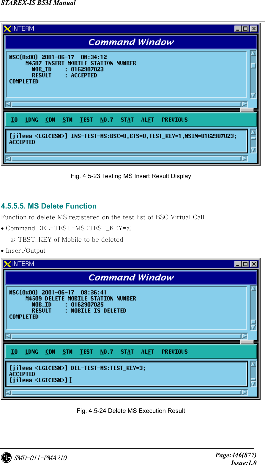
![STAREX-IS BSM Manual Page:445(877)Issue:1.0SMD-011-PMA210 Fig. 4.5-22 Presently registered Testing MS Display 4.5.5.4. MS Supplementary Function Function to register MS to be used for the BSC Virtual test. For a test of virtual call, first register MS. • Command INS-TEST-MS :BSC=a ,BTS=b ,TEST_KEY=c [,MSIN=d]; a: BSC number (0~11) b: BTS number (0~47) c: TEST KEY(1~100) d: IMSI of MS • Input/Output](https://usermanual.wiki/LG-Electronics-USA/3G1XOUTBTS.Users-Manual-Part-2/User-Guide-178514-Page-128.png)
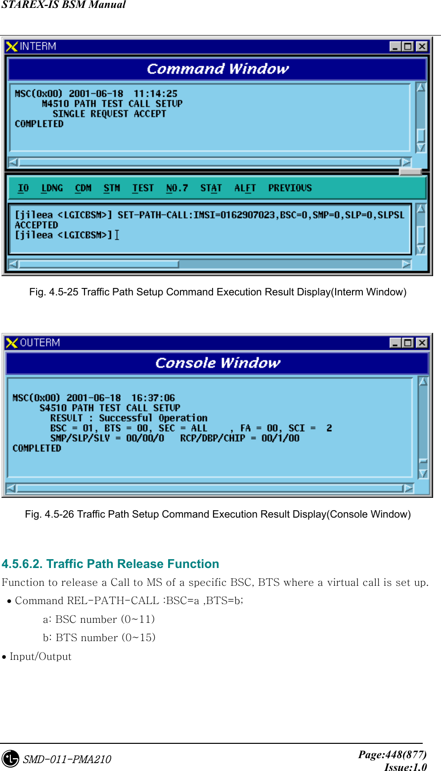
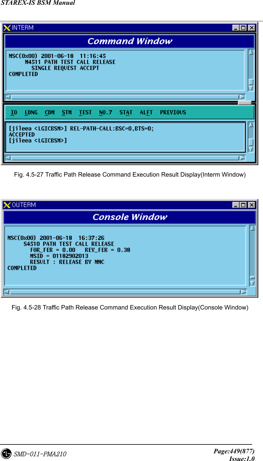
![STAREX-IS BSM Manual Page:447(877)Issue:1.0SMD-011-PMA210 4.5.6. TRAFFIC PATH TESTING FUNCTION it is a test enabling to decide if there is presence of failure with designated traffic path by setting a traffic path for BSC virtual call for a specific MS with the designated call resources and then measuring PER.. The kinds of virtual call include Markov and Loop Back., There are 8K and 13K respectively by service option. Call resources that the user can designate are as follows: Selector Slave Processor, Trunk, and BTS channel Chip. In one BSC, 100 virtual calls can be set up simultaneously separated from testing function of virtual call. Once a call is set up, a message type which is identical to the message type coming from BSC virtual call setup process is displayed. 4.5.6.1. Traffic Path Testing Setup Function Function to set up a Call for the designated Traffic Path • Command SET-PATH-CALL : IMSI=a , BSC=b , SMP=c , SLP=d , SLPSLV = e [,TRK = f], BTS= g ,SECTOR = h ,CDMA = i ,RCP= j , MCPA=k , CHIP=l , SCI=m , SCM=n , OPTI=o , DTYPE=p [,TIME=q]; a : IMSI b : BSC_Number(0~11) c : SMP_Number(0~4) d : SLP_Number(0~19) e : SLP_Slave_Number(0~3) f : Trunk_Number(0~19) g : BTS_Number(0~47) h : Sector_Id(0~5) i : CDMA_Channel_Number(0~11) j : RCP_Number(0~9) k : MCPA_Number(0~9) l : CHIP_Number(0~1) m : Slot_Cycle_Index(0~7) n : Station_Class_Mark(SLOT_M, NON_SLT_M) o : Service_Option(MKV_13K, MKV_8K, LB_13k, LB_8K) p : Test_data_Type(VARIABLE, RATE_FULL, RATE_HALF, RATE_QUAR, RATE_EIGHT) q : TRACE_TIME(1~60min) • Input/Output](https://usermanual.wiki/LG-Electronics-USA/3G1XOUTBTS.Users-Manual-Part-2/User-Guide-178514-Page-130.png)
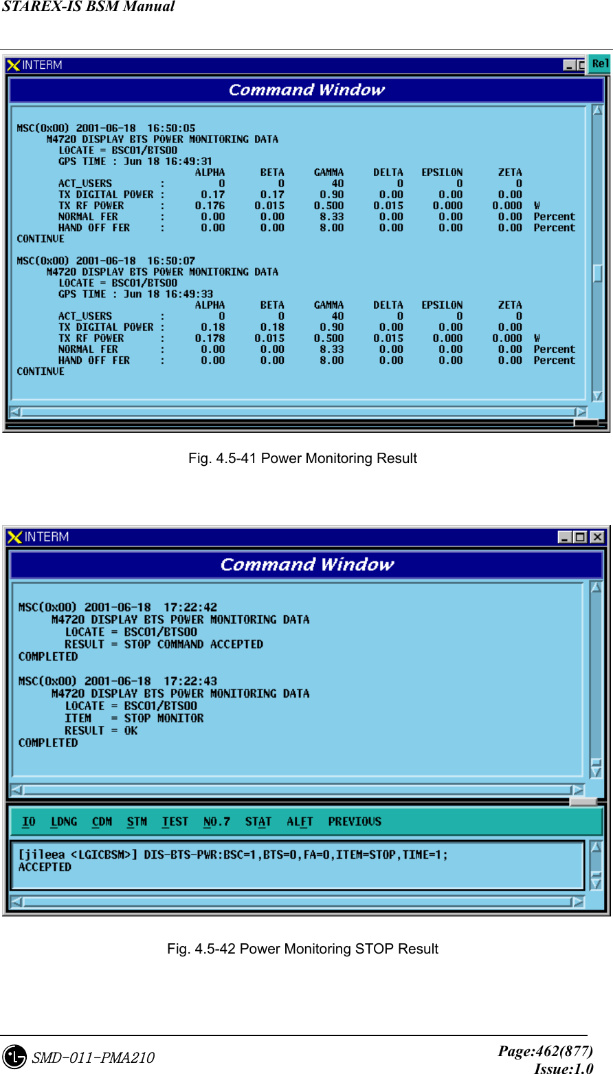
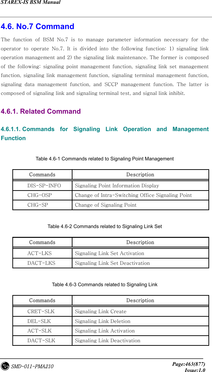
![STAREX-IS BSM Manual Page:461(877)Issue:1.0SMD-011-PMA210 4.5.11. POWER MONITORING Function Function to check the BTS power control in BSM • Command DIS-BTS-PWR:BSC=a,BTS=b,ITEM=c,[TIME=d]: a: BSC ID(0~11) b: BTS ID(0~47) c: Stop/Start d: Duration Time(1~100 min) • Input/Ouput Fig. 4.5-40 Power Monitoring START Result](https://usermanual.wiki/LG-Electronics-USA/3G1XOUTBTS.Users-Manual-Part-2/User-Guide-178514-Page-144.png)