LG Electronics USA 42PC5DUC Plasma Monitor User Manual MFL34797004 Edit1
LG Electronics USA Plasma Monitor MFL34797004 Edit1
Contents
- 1. Users Manual 1
- 2. Users Manual 2
- 3. Users Manual 3
Users Manual 2
PREPARATION
14
PREPARTION
■To prevent the equipment damage, never plug in any power cords until
you have finished connecting all equipment.
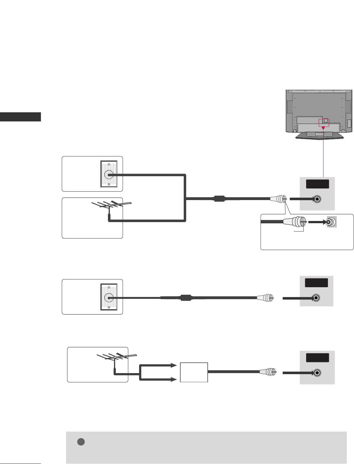
1. Antenna (Analog or Digital)
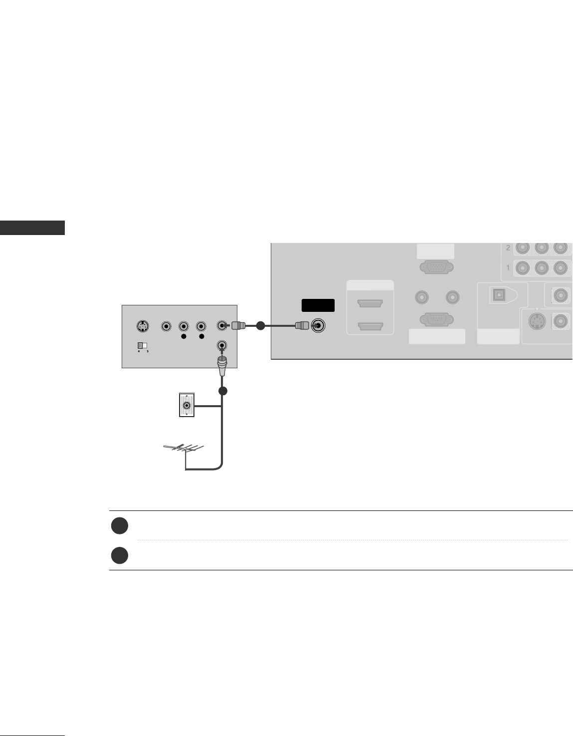
Wall Antenna Socket or Outdoor Antenna without a Cable Box Connections.
For optimum picture quality, adjust antenna direction if needed.
2. Cable
R
( )
Wall
Antenna
Socket
Outdoor
Antenna
(VHF, UHF)
Cable TV
Wall Jack
Multi-family Dwellings/Apartments
(Connect to wall antenna socket)
RF Coaxial Wire (75 ohm)
RF Coaxial Wire (75 ohm)
Single-family Dwellings /Houses
(Connect to wall jack for outdoor antenna) Be careful not to bend the bronze
wire when connecting the antenna.
Bronze Wire
R
( )
ANTENNA/
CABLE IN
R
( )
ANTENNA/
CABLE IN
R
( )
ANTENNA/
CABLE IN
GGThe TV will let you know when the analog, cable, and digital channel scans are complete.
NOTE
!
■To improve the picture quality in a poor signal area, please purchase a signal amplifier and install properly.
■If the antenna needs to be split for two TV’s, install a 2-Way Signal Splitter.
■If the antenna is not installed properly, contact your dealer for assistance.
Antenna
UHF
Signal
Amplifier
VHF
EXTERNAL EQUIPMENT SETUP
15
HD RECEIVER SETUP
EXTERNAL EQUIPMENT SETUP
This TV can receive Digital Over-the-air/Cable signals without an external digital set-top box. However, if you
do receive digital signals from a digital set-top box or other digital external device, refer to the figure as shown
below.
DIGITAL AUDIO
OUT
OPTICAL
AV OUT
AV IN 1
VIDEO
AUDIO
MONO
( )
S-VIDEO
COMPONENT IN
VIDEO
AUDIO
Y L RPBPR
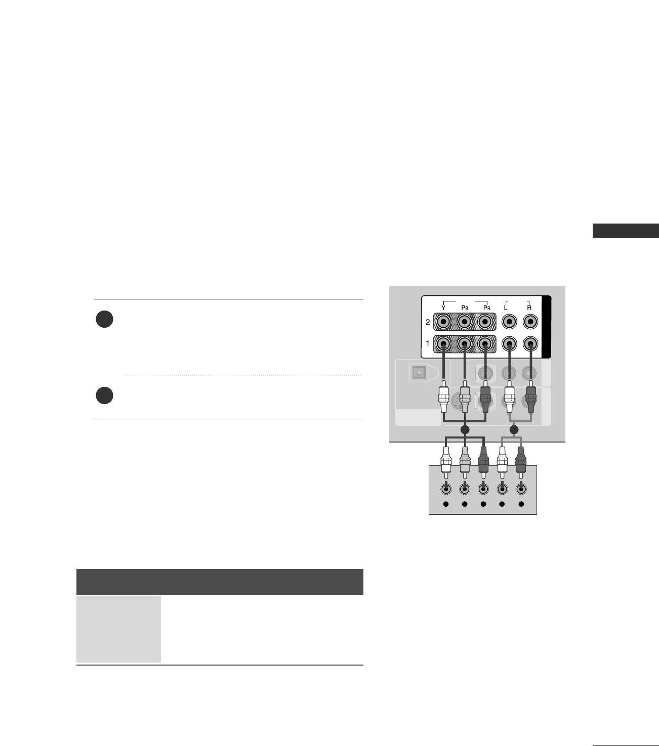
When connecting Component cable
1 2
1. How to connect
Connect the video outputs (Y, PB, PR)of the digital set
top box to the CCOOMMPPOONNEENNTT IINN VVIIDDEEOO 11jacks on
the set. Match the jack colors
(Y = green, PB= blue, and PR= red).
Connect the audio output of the digital set-top box to
the CCOOMMPPOONNEENNTT IINN AAUUDDIIOO 11jacks on the set.
2
1
2. How to use
■Turn on the digital set-top box.
(Refer to the owner’s manual for the digital set-top box.)
■Select CCoommppoonneenntt 11 input source with using the
IINNPPUUTT button on the remote control.
■If connected to CCOOMMPPOONNEENNTT IINN22 input, select
CCoommppoonneenntt 22 input source.
Signal
480i
480p
720p
1080 i
Component 1/2
Yes
Yes
Yes
Yes
HDMI1/DVI,
HDMI2
No
Yes
Yes
Yes
EXTERNAL EQUIPMENT SETUP
16
EXTERNAL EQUIPMENT SETUP
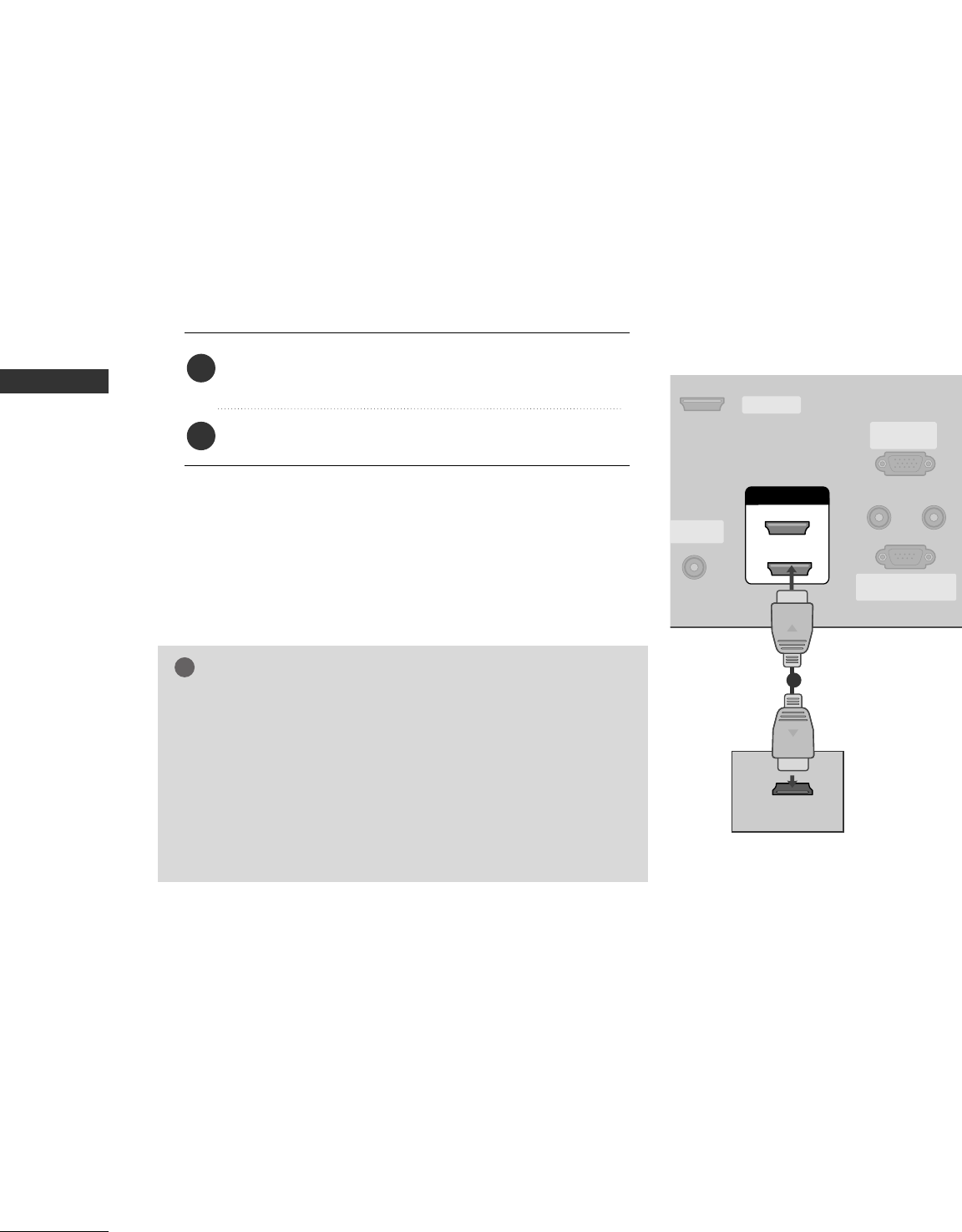
When connecting HDMI cable
Connect the digital set-top box to HHDDMMII//DDVVII IINN 11
or 22 jack on the set.
No separated audio connection is necessary.
1. How to connect
2. How to use
■Turn on the digital set-top box.
(Refer to the owner’s manual for the digital set-top box.)
■Select HHDDMMII11//DDVVIIor HHDDMMII22 input source with using
the IINNPPUUTTbutton on the remote control.
2
1
HDMI/DVI IN
ANTENNA/
CABLE IN
REMOTE
CONTROL IN
RS-232C IN
(CONTROL & SERVICE)
RGB IN
(PC)
AUDIO IN
(RGB/DVI)
1
2
SERVICE
HDMI-DTV OUTPUT
1
GGIf the digital set-top box supports Auto HDMI function, the
output resolution of the source device will be automatically
set to 1280x720p.
GGIf the digital set-top box player does not support Auto HDMI,
you need to set the output resolution appropriately.
To get the best picture quality, adjust the output resolution of
the source device to 1280x720p.
NOTE
!
EXTERNAL EQUIPMENT SETUP
17
HDMI/DVI IN
ANTENNA/
CABLE IN
REMOTE
CONTROL IN
RS-232C IN
(CONTROL & SERVICE)
RGB IN
(PC)
AUDIO IN
(RGB/DVI)
DIGITAL AUDIO
OUT
OPTICAL
1
2
SERVICE
COMPONENT IN AV OUT
AV IN 1
VIDEO
AUDIO
MONO
( )
S-VIDEO
VIDEO
AUDIO
L R
DVI-DTV OUTPUT
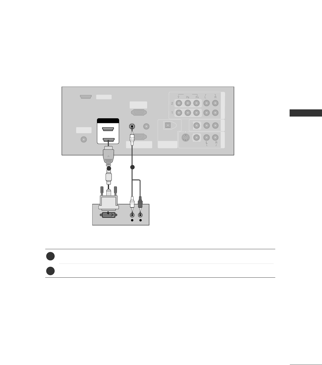
Connect the DVI output of the digital set-top box to the HHDDMMII//DDVVII IINN 11or 22 jack on the set.
Connect the audio output of the digital set-top box to the AAUUDDIIOO IINN ((RRGGBB//DDVVII))jack on the set.
1. How to connect
■Turn on the digital set-top box. (Refer to the owner’s manual for the digital set-top box.)
■Select HHDDMMII11//DDVVIIor HHDDMMII22input source with using the IINNPPUUTTbutton on the remote control.
2. How to use
2
1
12
When connecting HDMI to DVI cable
EXTERNAL EQUIPMENT SETUP
18
DVD SETUP
EXTERNAL EQUIPMENT SETUP
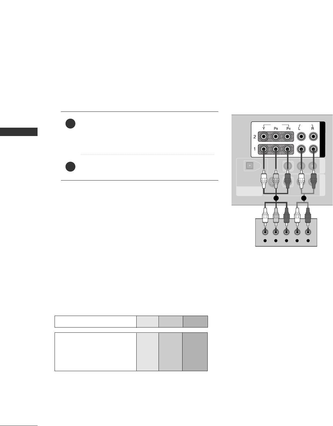
When connecting Component cable
DIGITAL AUDIO
OUT
OPTICAL
AV OUT
AV IN 1
VIDEO
AUDIO
MONO
( )
S-VIDEO
COMPONENT IN
VIDEO
AUDIO
Y L RPBPR
AUDIO
( )
Component Input ports
To get better picture quality, connect a DVD player to the component input ports as shown below.
Component ports on the TV
YPBPR
Video output ports
on DVD player
Y
Y
Y
Y
PB
B-Y
Cb
Pb
PR
R-Y
Cr
Pr
Connect the video outputs (Y, PB, PR)of the DVD to
the CCOOMMPPOONNEENNTT IINN VVIIDDEEOO11jacks on the set.
Match the jack colors
(Y = green, PB= blue, and PR= red).
Connect the audio outputs of the DVD to the
CCOOMMPPOONNEENNTT IINN AAUUDDIIOO11jacks on the set.
1. How to connect
2. How to use
■Turn on the DVD player, insert a DVD.
■Select CCoommppoonneenntt 11 input source with using the IINNPPUUTT
button on the remote control.
■If connected to CCOOMMPPOONNEENNTT IINN 22 input, select
CCoommppoonneenntt 22 input source.
■Refer to the DVD player's manual for operating instructions.
2
1
1 2
EXTERNAL EQUIPMENT SETUP
19
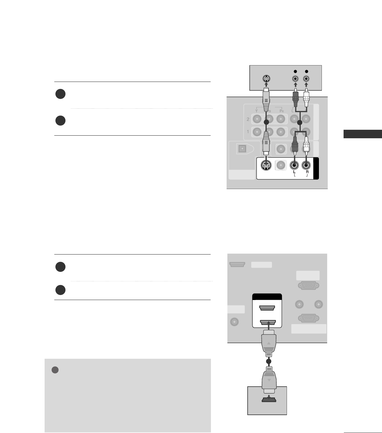
When connecting with an S-Video cable
DIGITAL AUDIO
OUT
OPTICAL
COMPONENT IN AV OUT
AV IN 1
VIDEO
S-VIDEO
VIDEO
AUDIO
AUDIOUDIO
MONO
( )
L R
S-VIDEO
AUDIO
12
HDMI/DVI IN
NTENNA/
CABLE IN
REMOTE
CONTROL IN
RS-232C IN
(CONTROL & SERVICE)
RGB IN
(PC)
AUDIO IN
(RGB/DVI)
1
2
SERVICE
HDMI-DVD OUTPUT
AUDIO
( )
1
Connect the S-VIDEO output of the DVD to the
SS--VVIIDDEEOOinput on the set.
Connect the audio outputs of the DVD to the AAUUDDIIOO
input jacks on the set.
1. How to connect
2. How to use
■Turn on the DVD player, insert a DVD.
■Select AAVV11input source with using the IINNPPUUTTbutton on
the remote control.
■If connected to AAVV IINN22, select AAVV22 input source.
■Refer to the DVD player's manual for operating instructions.
When connecting HDMI cable
Connect the HDMI output of the DVD to the
HHDDMMII//DDVVII IINN 11or 22jack on the set.
No separated audio connection is necessary.
1. How to connect
2. How to use
■Select HHDDMMII11//DDVVIIor HHDDMMII22input source with using
the IINNPPUUTTbutton on the remote control.
■Refer to the DVD player's manual for operating instructions.
2
1
2
1
GGIf the DVD supports Auto HDMI function, the DVD output
resolution will be automatically set to 1280x720p.
GGIf the DVD does not support Auto HDMI, you need to set
the output resolution appropriately.
To get the best picture quality, adjust the output resolution
of the DVD to 1280x720p.
NOTE
!
EXTERNAL EQUIPMENT SETUP
20
VCR SETUP
EXTERNAL EQUIPMENT SETUP
When connecting with an antenna
■To avoid picture noise (interference), leave an adequate distance between the VCR and TV
■Use the ISM feature in the Option menu to avoid having a fixed image remain on the screen for a long period
of time. If the 4:3 picture format is used; the fixed images on the sides of the screen may remain visible on
the screen. This phenomenon is common to all manufactures and in consequence the manufactures warranty
does not cover the product bearing this phenomenon.
HDMI/DVI IN
ANTENNA/
CABLE IN
REMOTE
CONTROL IN
RS-232C IN
(CONTROL & SERVICE)
RGB IN
(PC)
AUDIO IN
(RGB/DVI)
DIGITAL AUDIO
OUT
OPTICAL
1
2
VIDEO
S-VIDEO
L R
S-VIDEO VIDEO
OUTPUT
SWITCH
ANT IN
ANT OUT
VIDEO
AUDIO
( )
AUDIO
( )
Wall Jack
Antenna
1
2
Connect the RF antenna out socket of the VCR to the AAnntteennnnaasocket on the set.
Connect the antenna cable to the RF antenna in socket of the VCR.
1. How to connect
■Set VCR output switch to 3 or 4 and then tune TV to the same channel number.
■Insert a video tape into the VCR and press PLAY on the VCR. (Refer to the VCR owner’s manual.)
2. How to use
2
1
EXTERNAL EQUIPMENT SETUP
21
GGDo not connect to both Video
and S-Video at the same time. In
the event that you connect both
Video and the S-Video cables,
only the S-Video will work.
CAUTION
When connecting with a RCA cable
GGThe picture quality is improved: compared to normal
composite (RCA cable) input.
NOTE
!
N
DIGITAL AUDIO
OUT
OPTICAL
COMPONENT IN AV OUT
AV IN 1
S-VIDEO
VIDEO
AUDIO
VIDEO
AUDIO
MONO
( )
L R
S-VIDEO VIDEO
OUTPUT
SWITCH
ANT IN
ANT OUT
AUDIO
( )
VIDEO
AUDIO
( )
L R
S-VIDEO VIDEO
OUTPUT
SWITCH
ANT IN
ANT OUT
DIGITAL AUDIO
OUT
OPTICAL
COMPONENT IN AV OUT
VIDEO
AUDIO
AV IN 1
VIDEO
S-VIDEO AUDIO
MONO
( )
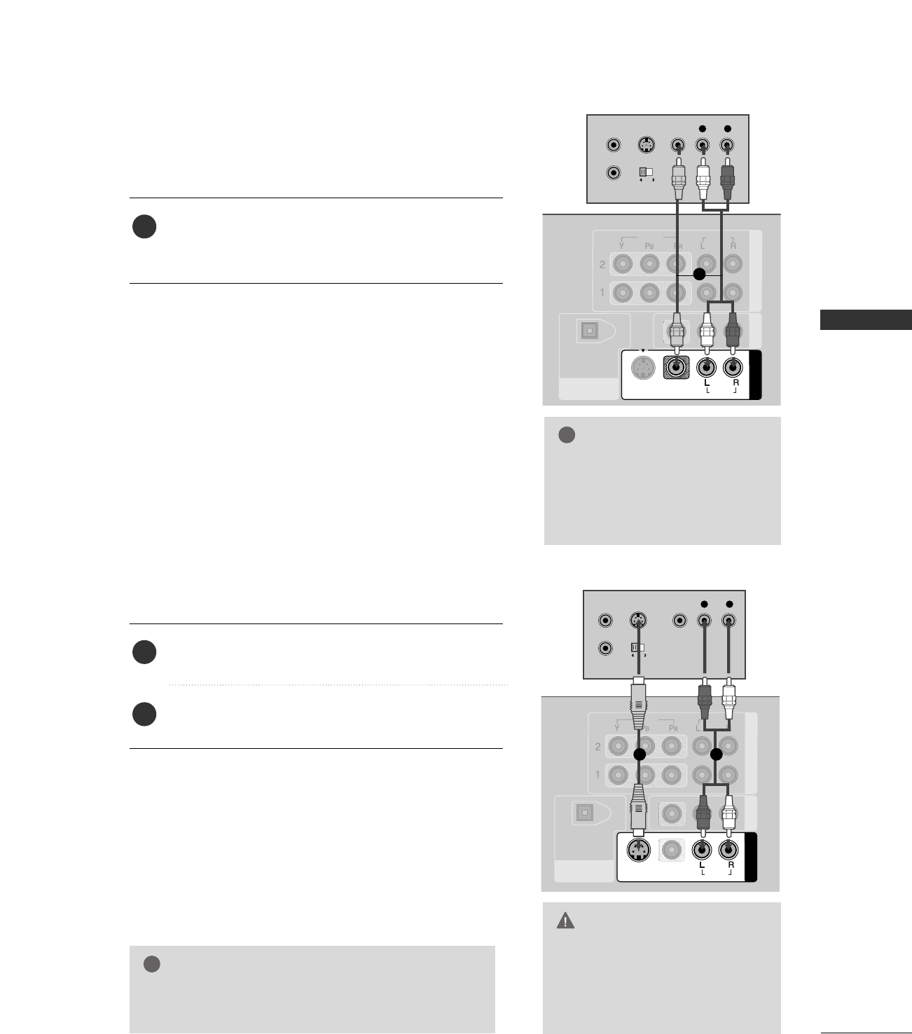
Connect the AAUUDDIIOO/VVIIDDEEOOjacks between TV and
VCR. Match the jack colors (Video = yellow, Audio Left
= white, and Audio Right = red)
1. How to connect
2. How to use
■Insert a video tape into the VCR and press PLAY on the
VCR. (Refer to the VCR owner’s manual.)
■Select AAVV11input source with using the IINNPPUUTTbutton on
the remote control.
■If connected to AAVV IINN22, select AAVV22 input source.
When connecting with an S-Video cable
Connect the S-VIDEO output of the VCR to the
SS--VVIIDDEEOO input on the set.
Connect the audio outputs of the VCR to the AAUUDDIIOO
input jacks on the set.
1. How to connect
2. How to use
■Insert a video tape into the VCR and press PLAY on the VCR.
(Refer to the VCR owner’s manual.)
■Select AAVV11input source with using the IINNPPUUTTbutton on
the remote control.
■If connected to AAVV IINN22, select AAVV22 input source.
1
2
1
GGIf you have a mono VCR, con-
nect the audio cable from the
VCR to the AAUUDDIIOO
LL//MMOONNOOjack of the set.
NOTE
!
1
12
EXTERNAL EQUIPMENT SETUP
22
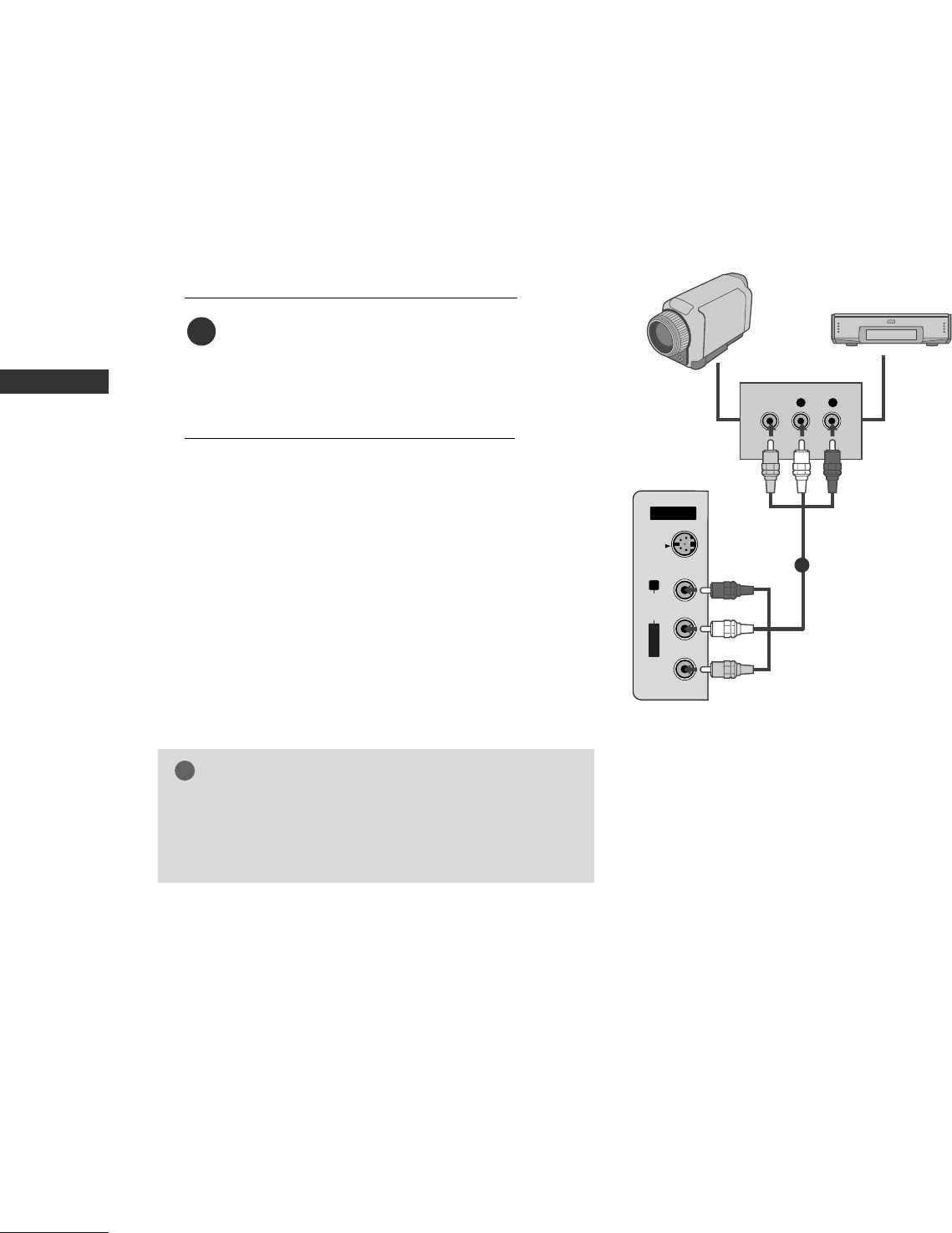
OTHER A/V SOURCE SETUP
EXTERNAL EQUIPMENT SETUP
AV IN 2
L/MONO
R
AUDIO
VIDEO
S-VIDEO
L R
VIDEO
Camcorder
Video Game Set
Connect the AAUUDDIIOO/VVIIDDEEOOjacks
between TV and external equipment.
Match the jack colors
.
(Video = yellow, Audio Left = white, and
Audio Right = red)
1. How to connect
2. How to use
■Select AAVV22 input source with using the
IINNPPUUTTbutton on the remote control.
■If connected to AAVV IINN11input, select AAVV11
input source.
■Operate the corresponding external equipment.
1
1
GGThis TV finds the connected input sources automati-
cally for AV1, AV2, Component 1-2, RGB,
HDMI1/DVI and HDMI2 sources are connected.
NOTE
!
EXTERNAL EQUIPMENT SETUP
23
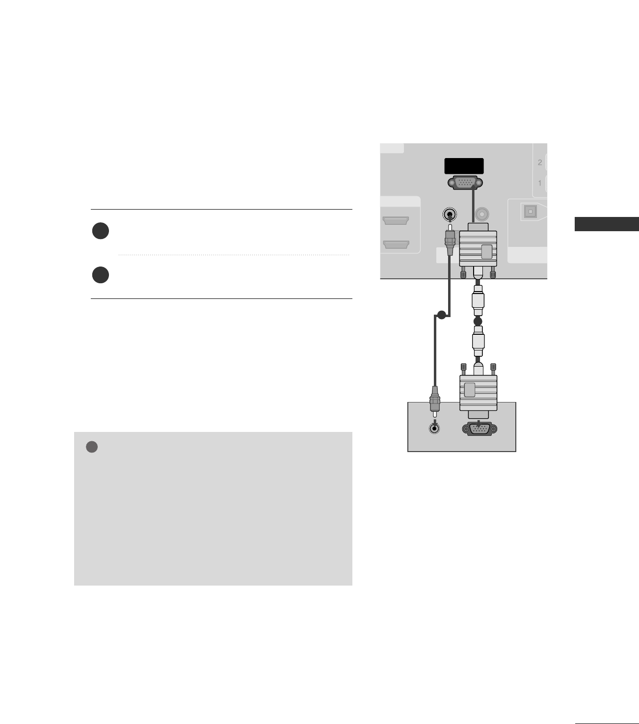
PC SETUP
This TV provides Plug and Play capability, meaning that the PC adjusts automatically to the TV's settings.
When connecting D-sub 15pin cable
GGCheck the image on your TV. There may be noise associ-
ated with the resolution, vertical pattern, contrast or
brightness in PC mode. If noise is present, change the PC
output to another resolution, change the refresh rate to
another rate or adjust the brightness and contrast on the
VIDEO menu until the picture is clear. If the refresh rate
of the PC graphic card can not be changed, change the
PC graphic card or consult the manufacturer of the PC
graphic card.
NOTE
!
RGB OUTPUTAUDIO
HDMI/DVI IN
REMOTE
CONTROL IN
RS-232C IN
(CONTROL & SERVICE)
RGB IN
(PC)
AUDIO IN
(RGB/DVI)
DIGITAL AUDIO
OUT
OPTICAL
1
2
ERVICE
Connect the RGB output of the PC to the RRGGBB IINN
((PPCC)) jack on the set.
Connect the PC audio output to the AAUUDDIIOO IINN
((RRGGBB//DDVVII))jack on the set.
1. How to connect
2. How to use
■Turn on the PC and the set.
■Select RRGGBB--PPCCinput source in main input option of
SETUP menu. ((GG pp..6677))
2
1
1
2
EXTERNAL EQUIPMENT SETUP
24
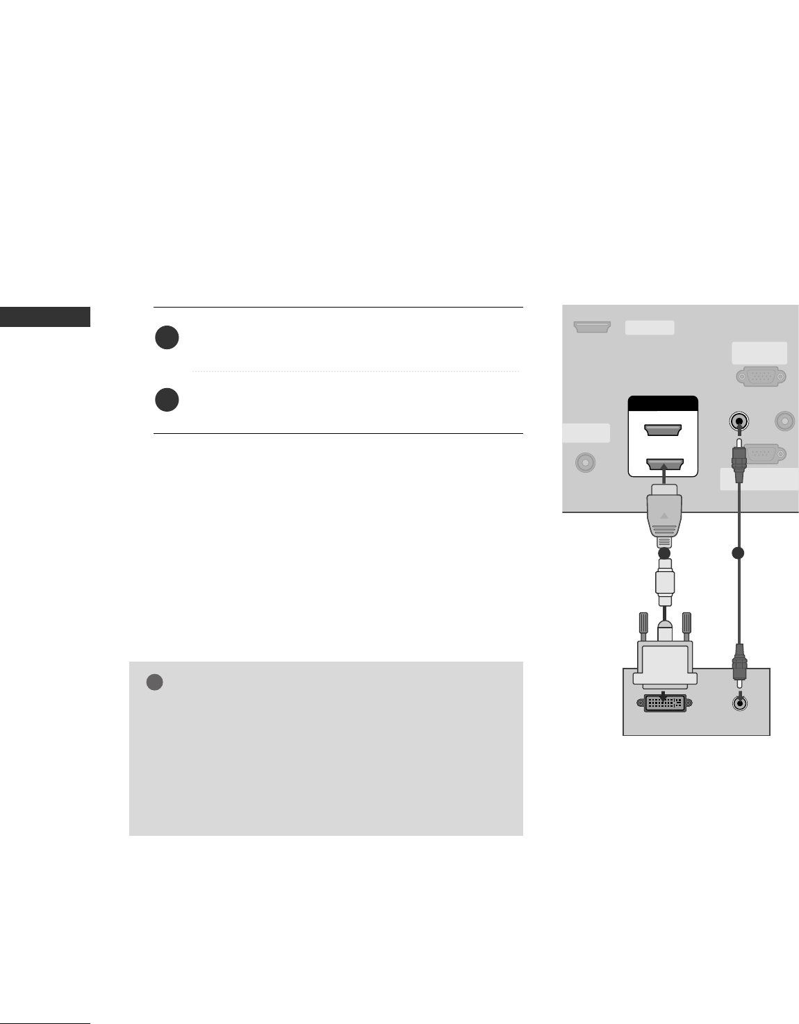
EXTERNAL EQUIPMENT SETUP
When connecting HDMI to DVI cable
ANTENNA/
CABLE IN
REMOTE
CONTROL
RS-232C IN
(CONTROL & SERVICE
RGB IN
(PC)
AUDIO IN
(RGB/DVI)
SERVICE
HDMI/DVI IN
1
2
DVI-PC OUTPUT AUDIO
12
GGIf the PC has a DVI output and no HDMI output, a sepa-
rated audio connection is necessary.
GGIf the PC does not support Auto DVI, you need to set the
output resolution appropriately. To get the best picture
quality, adjust the output resolution of PC graphics card's
output resolution to 1024x768, 60Hz.
NOTE
!
Connect the DVI output of the PC to the HHDDMMII//DDVVII
IINN 11or 22 jack on the set.
Connect the PC audio output to the AAUUDDIIOO IINN
((RRGGBB//DDVVII))jack on the set.
1. How to connect
2. How to use
■Turn on the PC and the set
■Select HHDDMMII11//DDVVIIor HHDDMMII22 input source with using
the IINNPPUUTTbutton on the remote control.
2
1
EXTERNAL EQUIPMENT SETUP
25
GGTo get the the best picture quality, adjust the PC
graphics card to 1024x768, 60Hz.
GGDepending on the graphics card, DOS mode may
not work if a HDMI to DVI Cable is in use.
GGWhen Source Devices are connected with
HDMI/DVI Input, the output PC Resolution (VGA,
SVGA, XGA, WXGA), Position and Size may not fit
on the Screen. Press the ADJUST button to adjust
the screen Position of the TV SET and contact a
PC graphics card service center.
GGWhen Source Devices connected with HDMI/DVI
Input, output TV SET Resolution (480p, 720p,
1080i, 1080p) and TV SET Display fit EIA/CEA-
861-B Specification to Screen. If not, refer to the
Manual of HDMI/DVI Source Devices or contact
your service center.
GGIf the HDMI/DVI Source Device is not connected
to the Cable or if there is a poor cable connec-
tion, "No signal" is displayed in the HDMI/DVI
Input. In this case, that Video Resolution is not
supported. If "Invalid Format" is displayed, refer to
the Source Device manual or contact your service
center.
GGAvoid keeping a fixed image on the screen for a
long period of time. The fixed image may become
permanently imprinted on the screen.
GGThe synchronization input form for Horizontal
and Vertical frequencies is separate.
NOTES
!
RGB-PC, HDMI1/DVI-PC mode
Horizontal Vertical
Frequency(KHz)Frequency(Hz)
31.469 70.08
31.469 70.08
31.469 59.94
37.879 60.31
48.363 60.00
47.776 59.87
47.720 59.799
47.130 59.65
Resolution
720x400
1360x768
640x350
* RGB-PC mode only: 640x350, 720X400
640x480
800x600
1024x768
HDMI1/DVI-DTV, HDMI2-DTV mode
Horizontal Vertical
Frequency(KHz)Frequency(Hz)
31.469 59.94
31.500 60.00
44.960 59.94
45.000 60.00
33.720 59.94
33.750 60.00
27.000 24.00
33.750 30.00
Resolution
720x480
1280x720
1920x1080i
1920x1080p
1280x768
1366x768
Supported Display Specifications
EXTERNAL EQUIPMENT SETUP
26
EXTERNAL EQUIPMENT SETUP
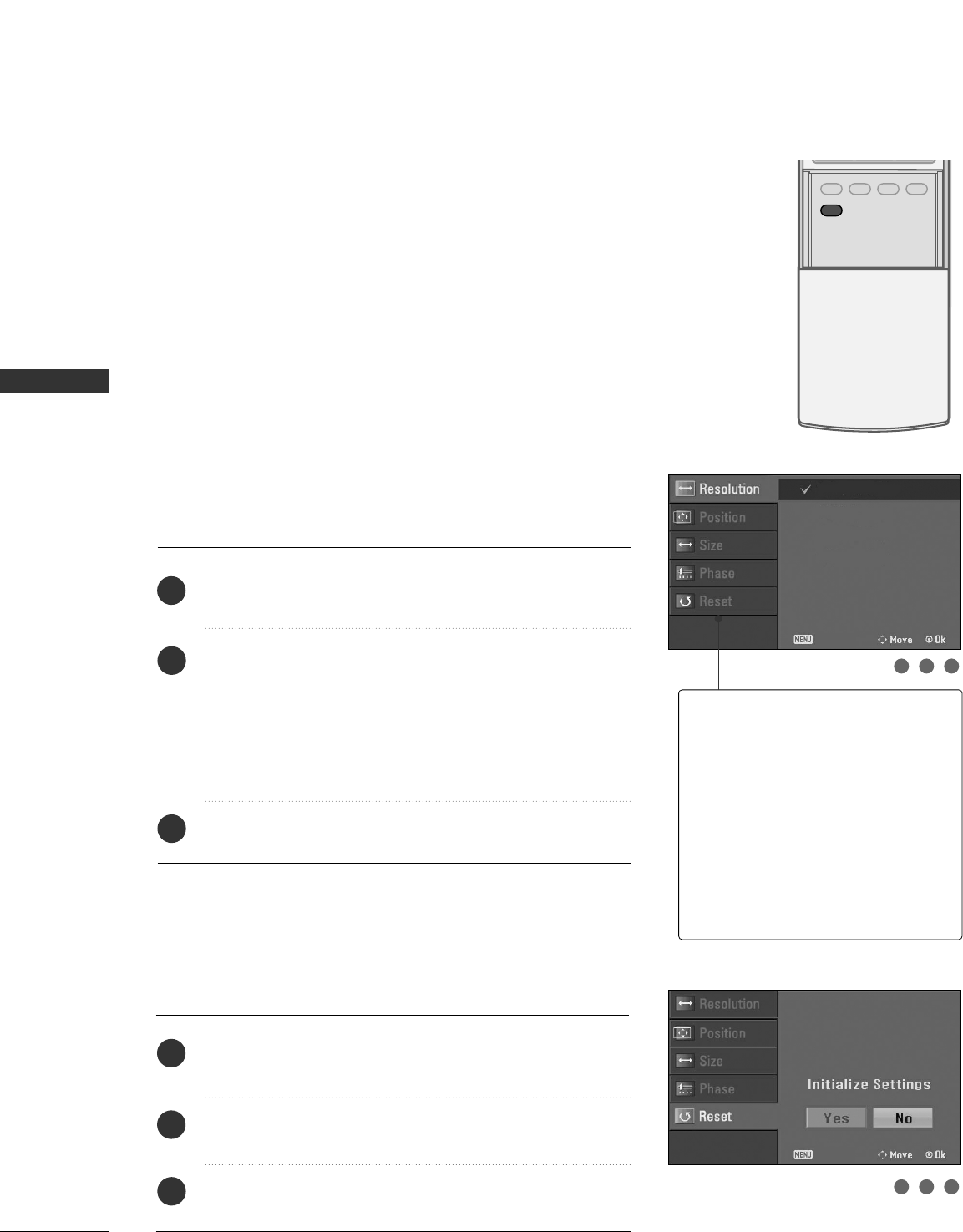
Screen Setup for PC mode
Overview
When RGB connect to PC output and select the RGB-PC in Input
source, this function is used.
When HDM/DVI connect to PC output and select HDMI/DVI input,
this function is used.
After connecting RGB-PC or HDMI/DVI to PC input and checking the
screen quality.
When you change the resolution, select the proper resolution in pre-
sent input to see the best picture appearance.
Adjustment for screen Resolution, Position, Size,
and Phase
Press the AADDJJUUSSTTbutton and then use DD or EEbutton to
select RReessoolluuttiioonn, PPoossiittiioonn, SSiizzee, or PPhhaassee.
Press the EENNTTEERRbutton and then use DD EE FFGG button to
make appropriate adjustments.
■The PPhhaasseeadjustment range is --1166 ~++1166.
In HDMI/DVI-PC mode, PPhhaassee is not available.
■The SSiizzeeadjustment range is --3300 ~++3300.
In HDMI/DVI-PC mode, SSiizzeeis not available.
Press the EENNTTEERRbutton.
Initializing (Reset to original factory values)
Press the AADDJJUUSSTTbutton and then use DD or EEbutton to
select RReesseett.
Press the EENNTTEERR button and then use FFor GG button to
select YYeess.
Press the EENNTTEERRbutton.
To initialize the adjusted values
ADJUST
SAP
SOUND
PICTURE
CC
1
2
3
1
2
3
RReessoolluuttiioonn
This function allows you select
resolution of XGA/WXGA.
PPoossiittiioonnThis function is to adjust picture to
left/right and up/down as you prefer.
SSiizzeeThis function is to minimize any ver-
tical bars or stripes visible on the
screen background. And the hori-
zontal screen size will also change.
PPhhaasseeThis function allows you to
remove any horizontal noise and
clear or sharpen the image of char-
acters.
123
123
1024 x 768
1280 x 768
1360 x 768
1366 x 768
Close
Close
EXTERNAL EQUIPMENT SETUP
27
AV OUT SETUP
The TV has a special signal output capability which allows you to hook up the second TV or monitor.
L R S-VIDEOVIDEO
L AUDIO
UT
ICAL
NT IN AV OUT
AV IN 1
VIDEO
AUDIO
MONO
( )
S-VIDEO
Connect the second TV or monitor to the TV’s AAVV OOUUTT
jacks.
See the Operating Manual of the second TV or monitor
for further details regarding that device’s input settings.
1. How to connect
GGComponent1-2, RGB-PC, HDMI1/DVI, HDMI2, DTV input
sources cannot be used for AV out.
GGWe recommend to use the AV OUT jacks for VCR recording.
NOTE
!
2
1
1
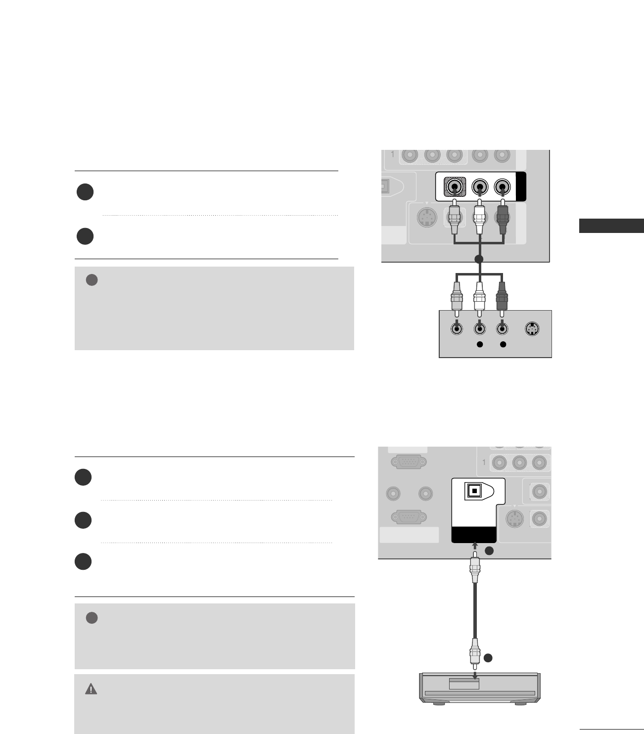
Send the TV’s audio to external audio equipment via the Digital Audio Output (Optical)port.
REMOTE
CONTROL IN
RS-232C IN
(CONTROL & SERVICE)
(PC)
AUDIO IN
(RGB/DVI)
VIDEO
S-VIDEO
DIGITAL AUDIO
OUT
OPTICAL
GGWhen connecting with external audio equipments, such as ampli-
fiers or speakers, please turn the TV speakers off. (GG pp..8844)
NOTE
!
GGDo not look into the optical output port. Looking at the
laser beam may damage your vision.
CAUTION
Connect one end of an optical cable to the TV Digital
Audio (Optical)Output port.
Connect the other end of the optical cable to the
digital audio (optical)input on the audio equipment.
Set the “TV Speaker option - Off” in the AUDIO
menu. (GGpp..8844). See the external audio equipment
instruction manual for operation.
1. How to connect
2
3
1
1
2
DIGITAL AUDIO OUTPUT
WATCHING TV / CHANNEL CONTROL
28
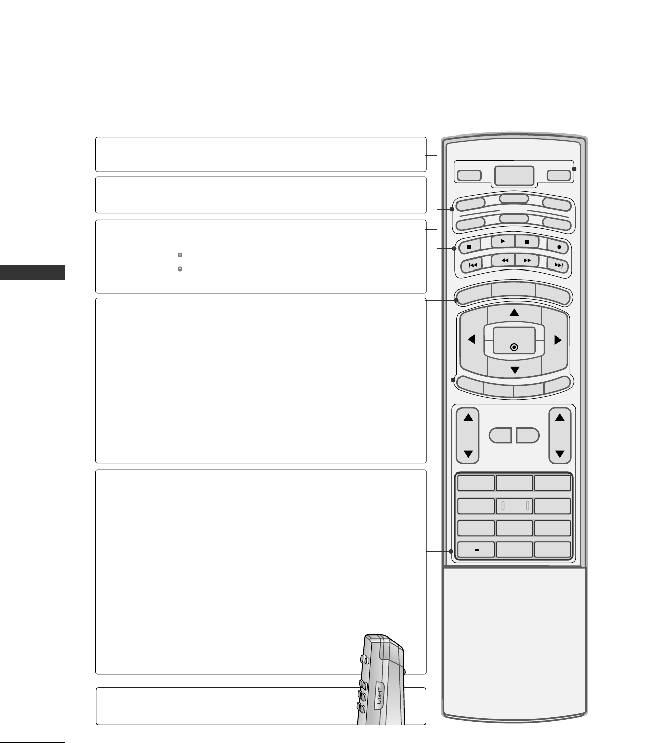
REMOTE CONTROL FUNCTIONS
WATCHING TV / CHANNEL CONTROL
1 2 3
4 5 6
78
0
9
BACK
VOL CH
MUTE
FAV
BRIGHT -
MENU
BRIGHT +
ENTER
EXIT
TIMER
RATIO
SIMPLINK
POWER
VCR
TV
DVD
AUDIO
CABLE
STB
MODE
TV INPUT
INPUT
MODE
MENU
BRIGHT -/ +
THUMBSTICK
(Up/Down/Left
Right/ENTER)
EXIT
TIMER
RATIO
SIMPLINK
VOLUME UP
/DOWN
MUTE
FAV
CHANNEL
UP/DOWN
— (DASH)
BACK
Select the remote operating mode: TV, DVD, VCR,
AUDIO, CABLE or STB.
Control video cassette recorders or DVD players.
Displays the main menu.
Adjust the brightness on screen.
It turns to the default settings brightness by changing
mode source.
Navigate the on-screen menus and adjust the system set-
tings to your preference.
Clear all on-screen displays and return to TV viewing
from any menu.
Select the amount of time before your TV turns off auto-
matically. GGpp..9900
Change the aspect ratio. GGpp..9922--9933
C? GGpp..9922--9933
Increase/decrease the sound level.
Switch the sound on or off. GGpp..3388
Scroll through the programmed Favorite channels.
Select available channels.
Used to enter a program number for multiple program
channels such as 2-1, 2-2, etc.
Tune to the last channel viewed.
VCR/DVD
control buttons
NUMBER button
When using the remote control, aim it at the remote control sensor on the TV.
Illuminates the remote control
buttons of selected mode.
LIGHT