LG Electronics USA 50PC3DUUE Plasma Display Panel User Manual 38289U0527F LG PDP
LG Electronics USA Plasma Display Panel 38289U0527F LG PDP
Contents
- 1. User Manual
- 2. User Manual 1
- 3. User Manual 2
- 4. User Manual 3
User Manual 1
11
Introduction
Connection Options
Connection Options
(Model Name: 32/37/42LC2DU)
(Model Name: 32/37/42LC2DU)
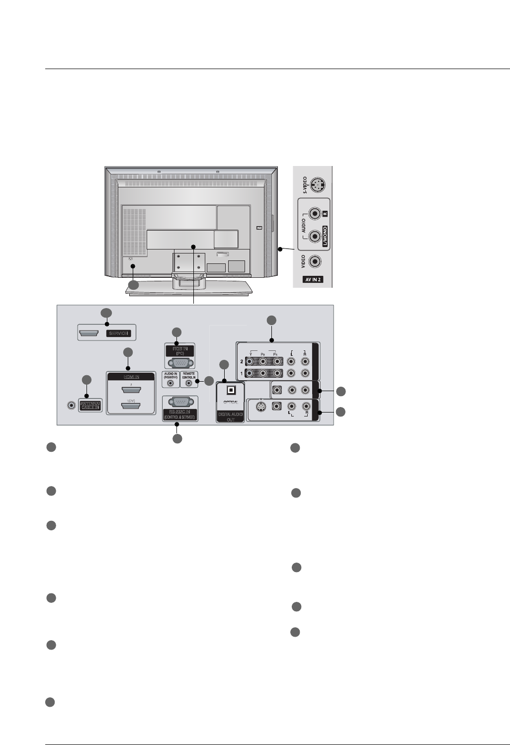
- This picture shown below may be somewhat different from your TV.
VIDEO
AUDIO
VIDEO
AUDIO
( )
S-VIDEO
AV IN 1
AV OUT
COMPONENT IN
AC IN
VIDEO
AUDIO
VIDEO
AUDIO
( )
S-VIDEO
AV IN 1
AV OUT
COMPONENT IN
VIDEO
AUDIO
VIDEO
AUDIO
( )
S-VIDEO
AV IN 1
AV OUT
COMPONENT IN
VIDEOVIDEO
AUDIOAUDIO
VIDEOVIDEO
AUDIOAUDIO
MONO
( )
S-VIDEOS-VIDEO
AV IN 1AV IN 1
AV OUTAV OUT
ANTENNA/
CABLE IN
RS-232C IN
(CONTROL & SERVICE)
RGB IN
(PC)
COMPONENT INCOMPONENT IN
DIGITAL AUDIO
OUT
O
PTICAL
SERVICE
HDMI IN
1(DVI)
2
S-VIDEO Input
Provides better picture quality than the
video input.
VIDEO Input
Connects the video signal from a video
device.
AUDIO Input
Connections are available for listening to
stereo sound from an external device.
COMPONENT IN
Connect a component video/audio device to
these jacks.
AV OUT
Connect a second TV or monitor.
AV (Audio/Video) IN 1
Connect audio/video output from an external
device to these jacks.
S-VIDEO
Connect S-Video out from an S-VIDEO device.
ANTENNA/CABLE IN
Connect over-the air signals to this jack.
Connect cable signals to this jack.
DIGITAL AUDIO OUT
Connect digital audio from various types of equip-
ment.
Note: In standby mode, these ports do not work.
HDMI IN
Connect a HDMI signal.
Or DVI (VIDEO)signal to the this port with a
HDMI to DVI cable.
RGB IN (PC)
Connect the monitor output from a PC to the
appropriate input port.
Remote Control Port
Connect your wired remote control.
AUDIO IN (RGB/DVI)
Connect the monitor output from a PC to the
appropriate input port.
RS-232C IN (CONTROL & SERVICE) PORT
Connect to the RS-232C port on a PC.
SERVICE
Power Cord Socket
For operation with AC power.
Caution:
Never attempt to operate the TV on DC power.
1
2
4
17
8
9
10
2
3
4
5
5
6
7
8
3
9
11
6
11
10
12
Introduction
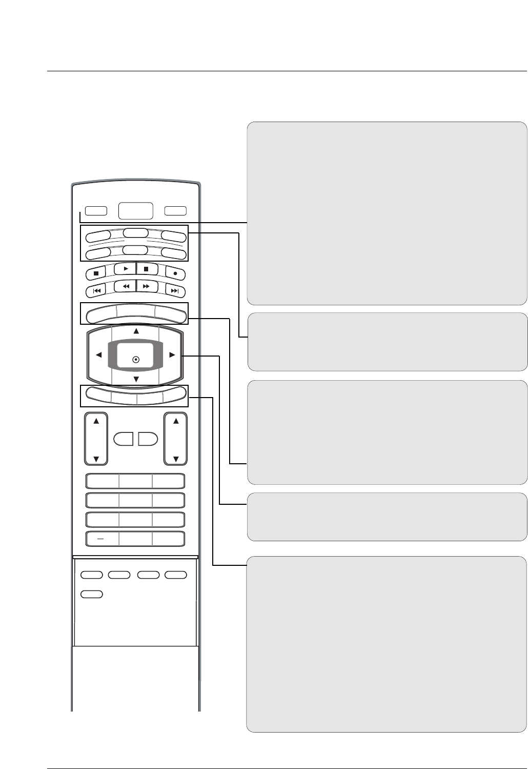
Remote Control Key Functions
Remote Control Key Functions
POWER
Turns your TV or any other programmed equipment on or
off, depending on mode.
VOL
CH
POWER
1 2 3
4 5 6
78
0
9
MENU
MUTE FAV
BRIGHT +
VCR
TV
DVD
ENTER
ADJUST
SAP
EZ SOUND
EZ PIC
CC
FLASHBK
EXIT
TIMER
RATIO
INFO
AUDIO
CABLE
STB
MODE
TV INPUT INPUT
BRIGHT -
TV INPUT
Rotates the input mode between Antenna and Cable. In AV1-
2, Component 1-2, RGB-DTV (or RGB-PC), HDMI1/DVI, and
HDMI2 input sources, screen returns to the last TV channel.
MODE
Selects the remote operating mode: TV, DVD, VCR, AUDIO,
CABLE, or STB. Select a mode other than TV, for the remote
to operate an external device.
INPUT
External input modes rotate in regular sequence: TV, AV1-2,
Component 1-2, RGB-PC, HDMI1/DVI or HDMI2.
(AV 1-2, Component 1-2, RGB-PC , HDMI1/DVI or HDMI2
input sources are linked automatically, only if these are con-
nected.)
EXIT
Clears all on-screen displays and returns to TV viewing from
any menu.
TIMER GGpp..4433
Lets you select the amount of time before your TV turns
itself off automatically.
RATIO GGpp..4455
Changes the aspect ratio.
MENU
Brings up the main menu to the screen.
BRIGHT + / -
- Adjust brightness on screen.
- It turns to the default settings brightness by changing mode
source.
THUMBSTICK (Up/Down/Left/Right/ENTER)
Allows you to navigate the on-screen menus and adjust the
system settings to your preference.
INFO (Refer to p.15)
When you watch the TV, information displays on top of the
screen. Not available in Component 1-2, RGB, HDMI1/DVI
and HDMI2 mode.
13
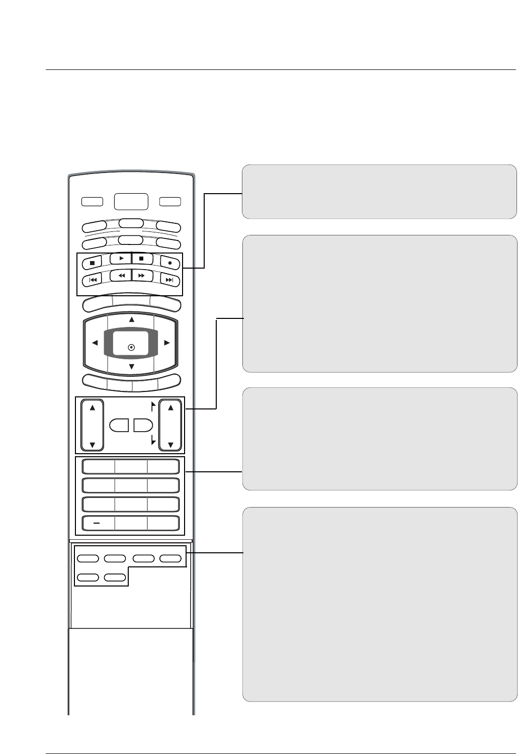
Introduction
EZ PIC GGpp..3333
Selects a factory preset picture mode depending on the view-
ing environment.
EZ SOUND GGpp..3399
Selects the sound appropriate for the program's character.
SAP
Selects MTS sound: Mono, Stereo, and SAP in analog mode.
Change the audio language in DTV mode.
CC GGpp..4466(*In DTV/CADTV mode GGpp..4466)
Select a closed caption: Off, CC1~4, Text1~4.
ADJUST
Adjusts screen position, size, and phase in PC mode.
FAV
Use to scroll the Favorite channels.
MUTE GGpp..2277
Switches the sound on or off.
CHANNEL UP/DOWN
Selects available channels found with EZ scan and Manual scan.
VOLUME UP/DOWN
Increases/decreases the sound level.
VOL
CH
POWER
1 2 3
4 5 6
78
0
9
MENU
MUTE FAV
DAY -
GUIDE
DAY+
RATIO
VCR
TV
DVD
ENTER
APM
ADJUST
SAP
EZ SOUND
EZ PIC
FREEZE
FLASHBK
PAGE
PAGE
EXIT
TIMER
CC
INFO
AUDIO
CABLE
STB
MODE
TV INPUT INPUT
— (DASH)
Used to enter a program number for multiple program chan-
nels such as 2-1, 2-2,etc.
NUMBER BUTTONS
FLASHBK
Returns to the last channel viewed.
VCR/DVD/DVHS/Camcorder BUTTONS
Control some video cassette recorders or DVD players
("RECORD" button is not available for DVD player).

14
Introduction
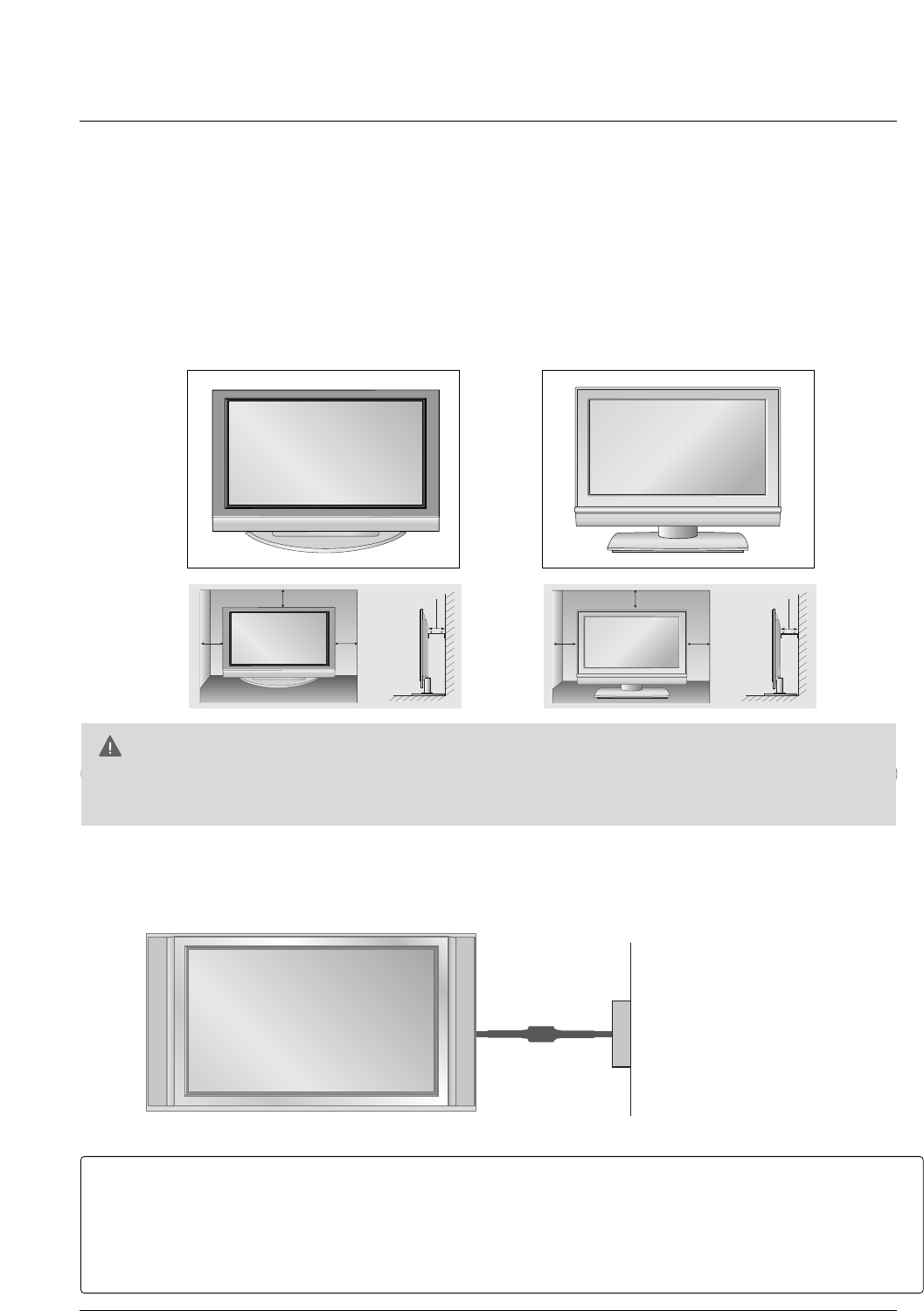
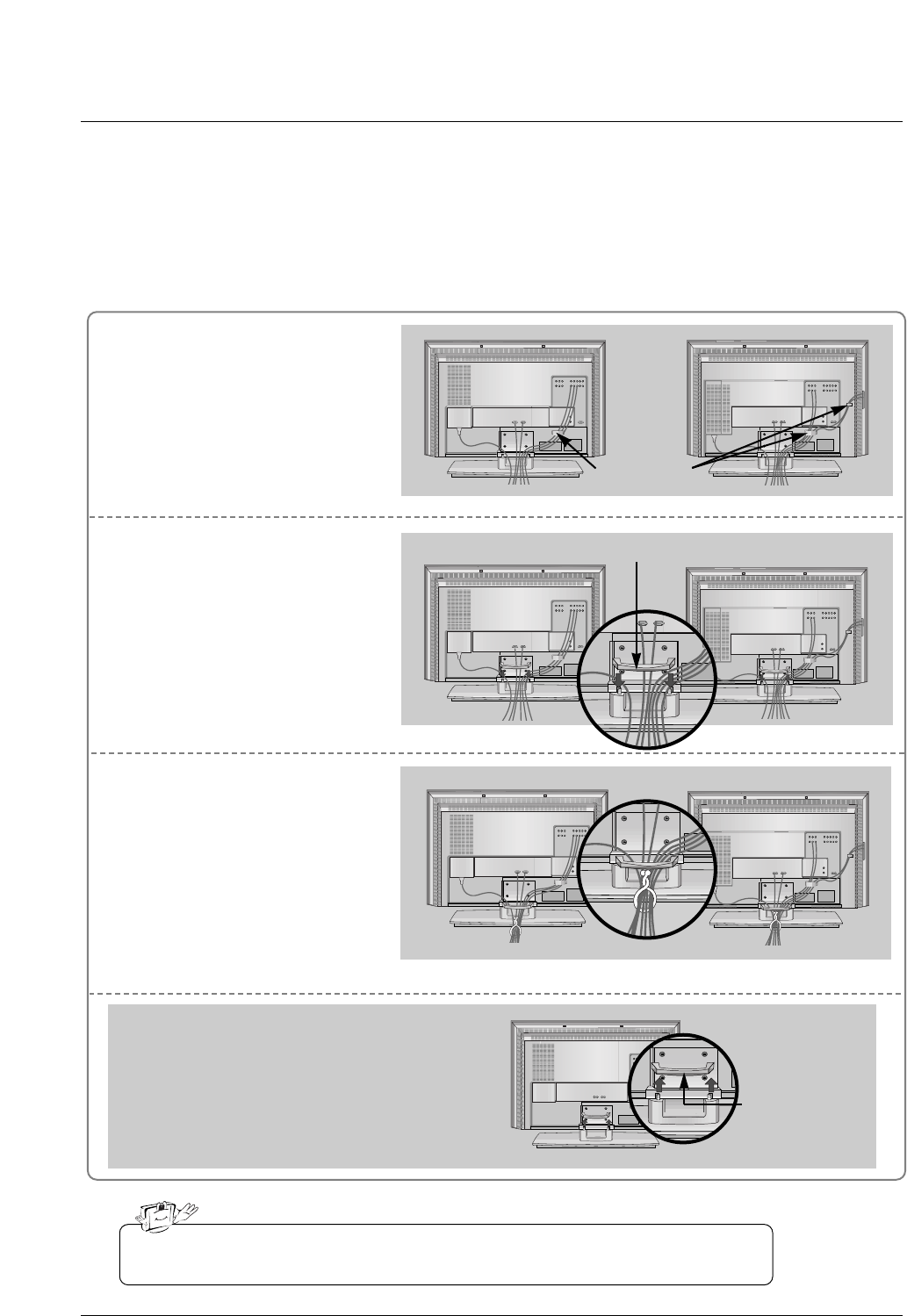
ATTACHING THE TV TO A WALL
We recommend that you set up the TV close to a wall so it cannot fall over if pushed backwards.
Additionally, we recommend that the TV be attached to a wall so it cannot be pulled in a forward direction, poten-
tially causing injury or damaging the product.
Caution: Please make sure that children don’t climb on or hang from the TV.
■Insert the eye-bolts (or TV brackets and bolts) to tighten the product to the wall as shown in the picture.
* If your product has the bolts in the eye-bolts position, loosen the bolts.
Secure the wall brackets with the bolts (not provided as parts of the product, must purchase separately)
on the wall. Match the height of the bracket that is mounted on the wall to the holes in the product.
Ensure the eye-bolts or brackets are tightened securely.
■Use a sturdy rope (not provided as parts of the product, must purchase sepa-
rately) to tie the product. It is safer to tie the rope so it becomes horizontal
between the wall and the product.
42PC3DU/3DVU/50PC3DU/60PC1D 32/37/42LC2DU
■Open the battery compartment cover on the
back side and install the batteries matching cor-
rect polarity (+with +,-with -).
■Install two 1.5V AA batteries. Don’t mix old or
used batteries with new ones.
■Close cover.
■Use a remote control up to 7 meters distance and
30 degree (left/right) within the receiving unit
scope.
■Dispose of used batteries in a recycle bin to pre-
serve environment.
OK
TVTV
INPUT
INPUT
DVD
ARC
EXIT
PIP PR + PIP INPUT
SWAP
PIP PR -
SLEEP
LIST
I/II
MENU
TEXT PIP
SIZE
POSITION
VCR
POWER
OK
TVTV
INPUT
INPUT
DVD
ARC
EXIT
PIP PR + PIP INPUT
SWAP
PIP PR -
Q.VIEW
SLEEP
LIST
I/II
MENU
TEXT PIP
SIZE
POSITION
VCR
POWER
OK
TVTV
INPUT
INPUT
DVD
ARC
EXIT
PIP PR + PIP INPUT
SWAP
PIP PR -
Q.VIEW
SLEEP
LIST
I/II
MENU
TEXT PIP
SIZE
POSITION
VCR
POWER
/32/37/42LC2DU
42PC3DU/3DVU/50PC3DU 60PC1D
Installing Batteries
Remote control effective range
15
Installation
Installation
Installation
For proper ventilation, allow a clearance of 4inches on each side from the wall.
GGEnsure adequate ventilation by following the clearance recommendations.
CAUTION
Power Supply
Short-circuit
Breaker
■This picture shown below may be somewhat different from your TV.
GROUNDING
Ensure that you connect the earth ground wire to prevent possible electric shock. If grounding methods
are not possible, have a qualified electrician install a separate circuit breaker.
Do not try to ground the unit by connecting it to telephone wires, lightening rods, or gas pipes.
DESKTOP PEDESTAL INSTALLATION
4 inches 4 inches
4 inches
4 inches
4 inches 4 inches
4 inches4 inches
32/37/42LC2DU42PC3DU/3DVU/50PC3DU/60PC1D
16
Connect the cables as necessary.
After connecting the cables neat-
ly, arrange the cables to the
Cable Holder.
To connect an additional equip-
ment, see the External equip-
ment Connections section.
Reinstall the CABLE MANAGE-
MENT as shown.
1
2
Bundle the cables using the sup-
plied twister holder.
3
Basic Connection (For 32/37/42LC2DU)
Basic Connection (For 32/37/42LC2DU)
32LC2DU
Cable holder
37/42LC2DU
32LC2DU 37/42LC2DU
32LC2DU 37/42LC2DU
Do not hold the CABLE MANAGEMENT when moving the product.
- If the product is dropped, you may be injured or the product may be broken.
How to remove
the CABLE MANAGEMENT
- Hold the CABLE MANAGEMENT with both hands
and pull it upward.
CABLE
MANAGEMENT
CABLE MANAGEMENT
17
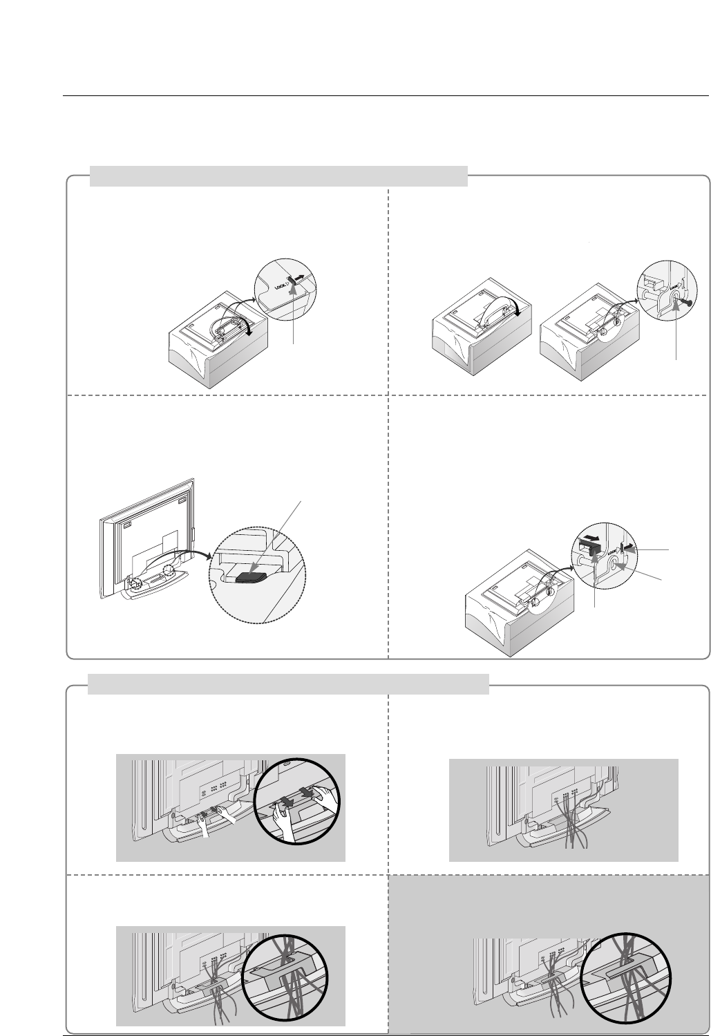
Place the set with the screen facing down on
a cushion or soft cloth as shown.
Before unfolding the stand, please make sure
two locks (A) on the bottom of the stand push
outward.
Pull the stand out as shown.
After unfolding the stand, please insert and
tighten the screws (provided as parts of the
product) in the holes (B) on the bottom of the
stand.
12
When connecting cables to the set, Do not
disengage the lock (C).
This may cause the set to fall, causing serious
bodily injury and serious damage to the set.
3
Basic Connection
Basic Connection
(C)
Hold the CABLE MANAGEMENT with both
hands and push it as shown.
Connect the cables as necessary.
To connect an additional equipment, see the
External equipment Connections section.
Reinstall the CABLE MANAGEMENT as
shown.
12
3
* Image shown here may be slightly different from
your set.
When closing the stand for storage
- First remove the screws in the holes (B) on the bottom
of the stand. And then pull two Hooks (D) of the stand
bottom and fold the stand into the back of the set.
- After folding, push the two Locks (A) of the stand
bottom outward.
(A)
(B)
(D)
(A)
(B)
How to use stand (For 42PC3DU/3DVU)
How to arrange the cable (For 50PC3DU)
For 60PC1D, 42PC3DU/3DVU
Arrange the cable as shown.
18
Installation
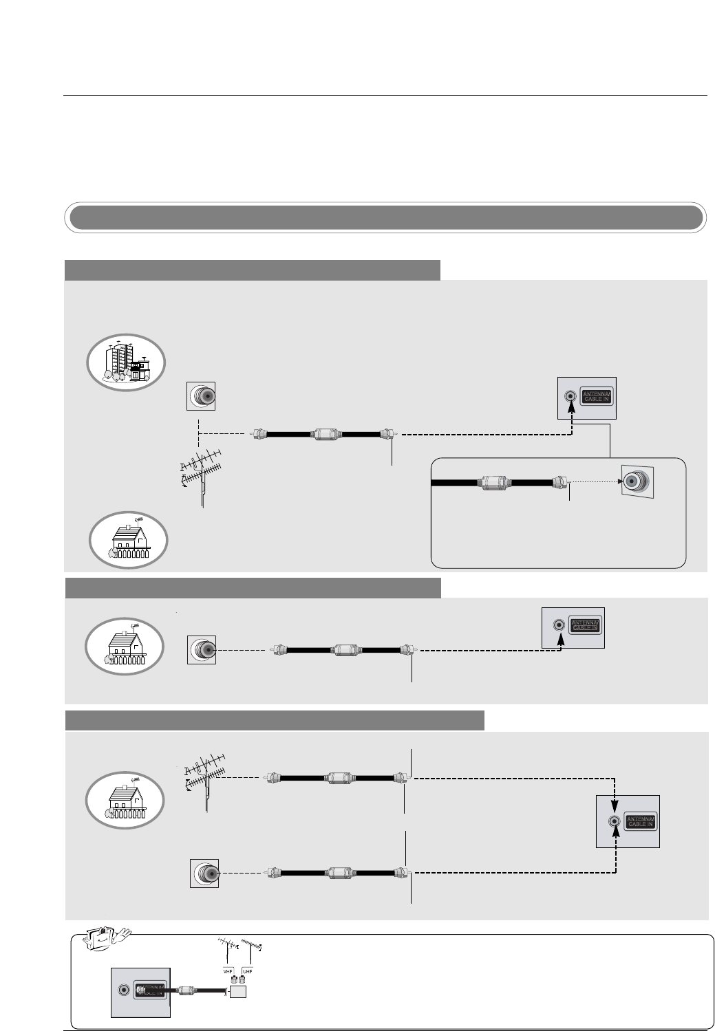
Antenna Or Cable Connection
Multi-family Dwellings/Apartments
(Connect to wall antenna socket)
Single-family Dwellings /Houses
(Connect to wall jack for outdoor antenna)
Outdoor Antenna
Wall Antenna Socket
VHF Antenna
UHF Antenna
RF Coaxial Wire (75 ohm)
Turn clockwise to tighten.
VIDEO
AUDIO
VIDEO
AUDIO
( )
S-VIDEO
AV IN 1
AV OUT
ANTENNA/
CABLE IN
COMPONENT IN
DIGITAL AUDIO
OUT
OPTICAL
VIDEO
AUDIO
VIDEO
AUDIO
( )
S-VIDEO
AV IN 1
AV OUT
COMPONENT IN
Bronze Wire
Be careful not to bend the bronze wire when
connecting the antenna.
Analog and Digital TV signals provided on antenna
- Antenna or Cable Service without a Cable Box Connection.
- For optimum picture quality, adjust antenna direction if needed.
Analog and DTV signals provided on two separate antennas
Cable TV Wall Jack
RF Coaxial Wire (75 ohm)
Bronze Wire
Bronze Wire
Turn clockwise to tighten.
Antenna
RF Coaxial Wire (75 ohm)
•In a poor signal area to improve picture quality, purchase and install a sig-
nal amplifier.
•If the antenna needs to be split for two TV’s, install a “2-Way Signal Splitter”
in the connections.
•If the antenna is not installed properly, contact your dealer for assistance.
VIDEO
AUDIO
VIDEO
AUDIO
( )
S-VIDEO
AV IN 1
AV OUT
ANTENNA/
CABLE IN
COMPONENT IN
DIGITAL AUDIO
OUT
OPTICAL
VIDEO
AUDIO
VIDEO
AUDIO
( )
S-VIDEO
AV IN 1
AV OUT
COMPONENT IN
External Equipment Connections
External Equipment Connections
signal
amplifier
VIDEO
AUDIO
VIDEO
AUDIO
( )
S-VIDEO
AV IN 1
AV OUT
ANTENNA/
CABLE IN
COMPONENT IN
DIGITAL AUDIO
OUT
OPTICAL
VIDEO
AUDIO
VIDEO
AUDIO
( )
S-VIDEO
AV IN 1
AV OUT
COMPONENT IN
NOTE: All cables shown are not included with the TV
Cable TV Wall Jack
RF Coaxial Wire (75 ohm)
Turn clockwise to tighten.
Analog and Digital TV signals provided on cable
VIDEO
AUDIO
VIDEO
AUDIO
( )
S-VIDEO
AV IN 1
AV OUT
ANTENNA/
CABLE IN
COMPONENT IN
DIGITAL AUDIO
OUT
OPTICAL
VIDEO
AUDIO
VIDEO
AUDIO
( )
S-VIDEO
AV IN 1
AV OUT
COMPONENT IN
19
Installation
- To avoid picture noise (interference), leave an adequate distance between the VCR and TV.
- Typically a frozen still picture from a VCR. If the 4:3 picture format is used; the fixed images on the sides
of the screen may remain visible on the screen.
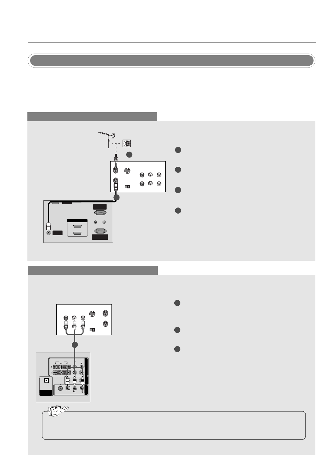
VCR Setup
When connecting with an antenna
VIDEO
AUDIO
VIDEO
AUDIO
( )
S-VIDEO
AV IN 1
AV OUT
COMPONENT IN
DIGITAL AUDIO
OUT
OPTICAL
S-VIDEO OUT
IN
(R) AUDIO (L) VIDEO
34
OUTPUT
SWITCH
ANT OUT
ANT IN
ANTENNA/ANTENNA/
CABLE INCABLE IN
REMOTEREMOTE
CONTROL INCONTROL IN
RS-232C IN
(CONTROL(CONTROL & SER & SERVICE)VICE)
RGB INRGB IN
(PC)(PC)
AUDIO INAUDIO IN
(RGB/DVI)(RGB/DVI)
VIDEO
AUDIO
VIDEO
AUDIO
( )
S-VIDEO
AV IN 1
AV OUT
COMPONENT IN
DIGITAL AUDIO
OUT
OPTICAL
SERVICESERVICE
HDMI IN HDMI IN
1(DVI)1(DVI)
2
When connecting with a RCA cable
VIDEO
AUDIO
VIDEO
AUDIO
( )
S-VIDEO
AV IN 1
AV OUT
COMPONENT IN
DIGITAL AUDIO
OUT
OPTICAL
S-VIDEO
OUT
IN
(R) AUDIO (L) VIDEO
34
OUTPUT
SWITCH
ANT OUT
ANT IN
HDMI / DVI IN
ANTENNA/
CABLE IN
REMOTE
CONTROL IN
RS-232C IN
(CONTROL & SERVICE)
RGB IN
(PC)
AUDIO IN
(RGB/DVI)
VIDEOVIDEO
AUDIOAUDIO
VIDEOVIDEO
AUDIOAUDIO
MONO
( )
S-VIDEOS-VIDEO
AV IN 1V IN 1
AV OUTV OUT
COMPONENTCOMPONENT IN
DIGITDIGITALAL AUDIO AUDIO
OUTOUT
OPTICALPTICAL
SERVICE
VCR
1
2
3
Connect the AUDIO/VIDEO jacks between TV
and VCR. Match the jack colors (Video = yellow,
Audio Left = white, and Audio Right = red)
Insert a video tape into the VCR and press PLAY
on the VCR. (Refer to the VCR owner’s manual.)
Select AV1 input source using the INPUT button
on the remote control.
- If connected to AV IN2, select AV2 input source.
•If you have a mono VCR, connect the audio cable from the VCR to the AUDIO L/MONO jack of the
set.
1
1
2
3
4
Connect the RF antenna out socket of the VCR to
the Antenna socket on the set.
Connect the antenna cable to the RF antenna in
socket of the VCR.
Set VCR output switch to 3 or 4 and then tune TV
to the same channel number.
Insert a video tape into the VCR and press PLAY
on the VCR. (Refer to the VCR owner’s manual.)
VCR
1
2
20
Installation
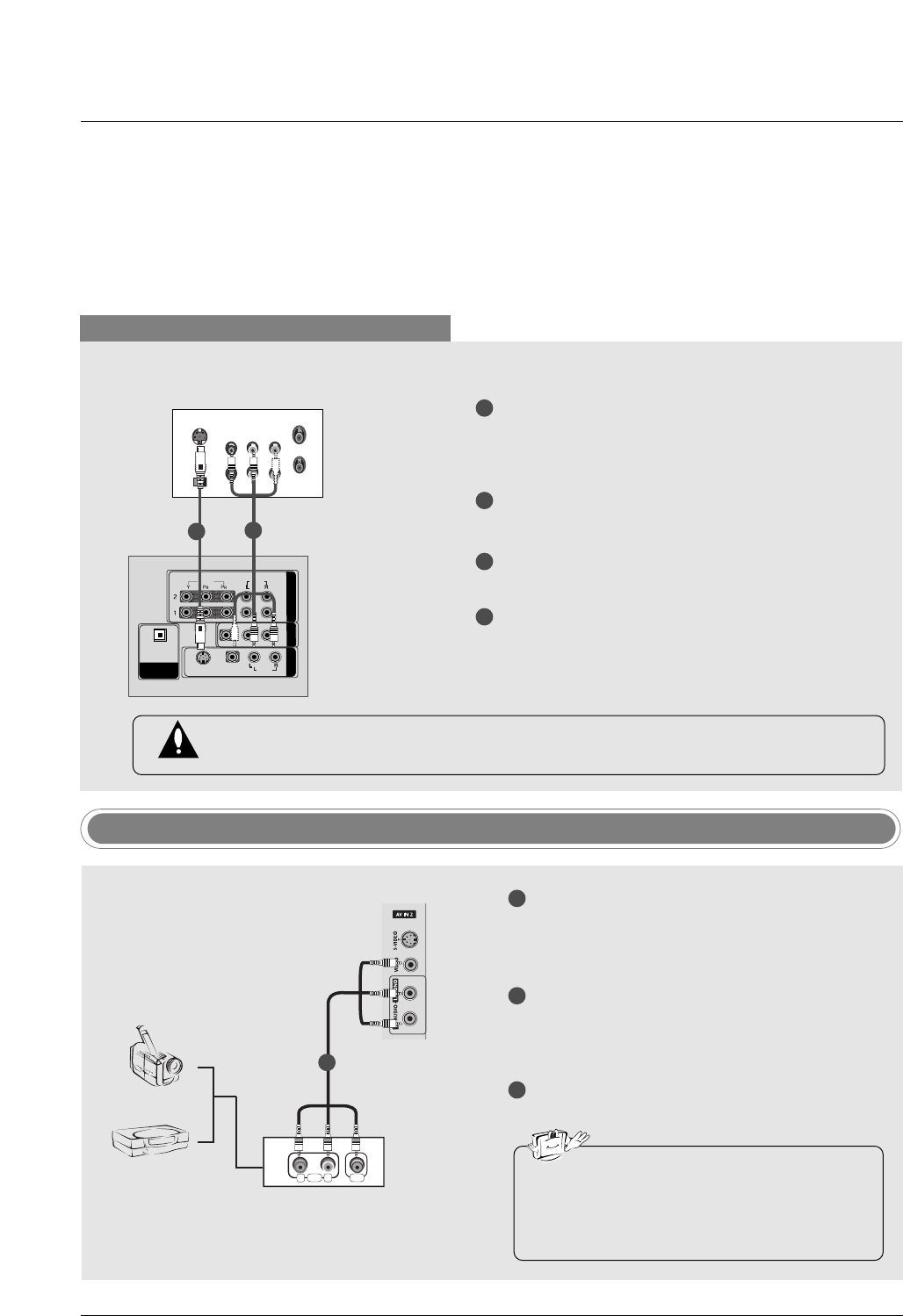
When connecting with an S-Video cable
VIDEOVIDEO
AUDIO
VIDEOVIDEO
AUDIOAUDIO
MONO
( )
S-VIDEOS-VIDEO
AV IN 1V IN 1
AV OUTV OUT
COMPONENTCOMPONENT IN
DIGITDIGITALAL AUDIO AUDIO
OUT
OPTICALPTICAL
S-VIDEO
OUT
IN
(R) AUDIO (L) VIDEO
34
OUTPUT
SWITCH
ANT OUT
ANT IN
HDMI / DVI IN
ANTENNA/
CABLE IN
REMOTE
CONTROL IN
RS-232C IN
(CONTROL & SERVICE)
RGB IN
(PC)
AUDIO IN
(RGB/DVI)
VIDEO
AUDIO
VIDEO
AUDIO
( )
S-VIDEO
AV IN 1
AV OUT
COMPONENT IN
DIGITAL AUDIO
OUT
OPTICAL
SERVICE
VCR
1
1
2
2
3
4
Connect the S-VIDEO output of the VCR to the S-
VIDEO input on the set. The picture quality is
improved; compared to normal composite (RCA
cable) input.
Connect the audio outputs of the VCR to the
AUDIO input jacks on the set.
Insert a video tape into the VCR and press PLAY
on the VCR. (Refer to the VCR owner’s manual.)
Select AV1 input source with using the INPUT
button on the remote control.
- If connected to AV IN2, select AV2 input source.
Do not connect to both Video and S-Video at the same time. In the event that you connect
both Video and the S-Video cables, only the S-Video will work.
R
L
AUDIO VIDEO
Camcorder
Video Game Set
1
1
2
3
Connect the AUDIO/VIDEO jacks between TV
and external equipment. Match the jack colors
(Video = yellow, Audio Left = white, and Audio
Right = red).
Select AV2 input source with using the INPUT
button on the remote control.
- If connected to AV IN1 input, select AV1 input
source.
Operate the corresponding external equipment.
Refer to external equipment operating guide.
External AV Source Setup
•This TV finds the connected input sources
automatically for AV1, AV2, Component 1-2,
RGB, HDMI1/DVI and HDMI2 sources are
connected.
21
Installation
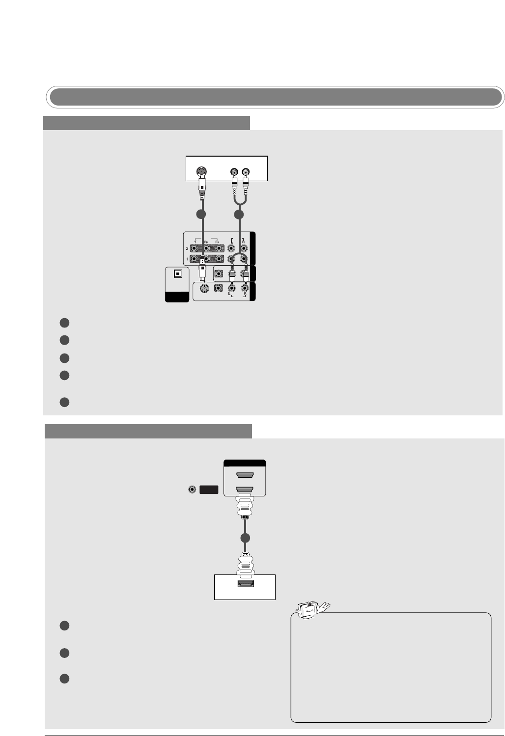
DVD Setup
When connecting with a S-Video cable
HDMI / DVI IN
ANTENNA/
CABLE IN
VIDEO
AUDIOAUDIO
VIDEO
AUDIOAUDIO
MONO
( )
S-VIDEOS-VIDEO
AV IN 1V IN 1
AV OUTV OUT
COMPONENTCOMPONENT IN IN
DIGITDIGITALAL AUDIO AUDIO
OUTOUT
OPTICAL
VIDEO
AUDIO
COMPONENT IN
S-VIDEO (R) AUDIO (L)
DVD
1
1
2
2
3
4
5
Connect the S-VIDEO output of the DVD to the S-VIDEO input on the set.
Connect the audio outputs of the DVD to the AUDIO input jacks on the set.
Turn on the DVD player, insert a DVD.
Select AV1 input source with using the INPUT button on the remote control.
- If connected to AV IN2, select AV 2 input source.
Refer to the DVD player's manual for operating instructions.
When connecting with a HDMI cable
1
2
3
Connect the HDMI output of the DVD to the HDMI
IN 1(DVI) or 2jack on the set.
Select HDMI1/DVI or HDMI2 input source with
using the INPUT button on the remote control.
Refer to the DVD player's manual for operating
instructions.
ANTENNA/
CABLE IN
VIDEO
AUDIO
VIDEO
AUDIO
( )
S-VIDEO
AV IN 1
AV OUT
COMPONENT IN
DIGITAL AUDIO
OUT
OPTICAL
VIDEO
AUDIO
COMPONENT IN
HDMI-DVD OUTPUT
HDMI IN HDMI IN
1(DVI)1(DVI)
2
DVD
1
•TV can receive the video and audio signal
simultaneously with using a HDMI cable.
•If the DVD supports Auto HDMI function, the
DVD output resolution will be automatically
set to 1280x720p.
•If the DVD does not support Auto HDMI, you
need to set the output resolution appropriate-
ly. To get the best picture quality, adjust the
output resolution of the DVD to 1280x720p.