LG Electronics USA 50PC3DXUD Plasma Display Panel User Manual 38289U0527Aen Rev06 ING
LG Electronics USA Plasma Display Panel 38289U0527Aen Rev06 ING
Contents
- 1. User Manual 1
- 2. User Manual 2
- 3. User Manual 3
User Manual 2
11
Introduction
Connection Options
Connection Options (Model Name: 42PC1D**/42PC3D**/50PC3D**)
(Model Name: 42PC1D**/42PC3D**/50PC3D**)
AV IN 2
AV IN 2
L/
L/
MONO
MONO
R
AUDIO
AUDIO
S-VIDEO
S-VIDEO
VIDEO
VIDEO
HDMI/DVI IN
HDMI/DVI IN
DIGITAL AUDIO
DIGITAL AUDIO
OUT
OUT
OPTICAL
PTICAL
RS-232C IN
RS-232C IN
(CONTROL
(CONTROL
&
SERVICE)
SERVICE)
RGB (PC
RGB (PC
/DTV)
DTV)
RGB IN
RGB IN
AUDIO (RGB/DVI)
AUDIO (RGB/DVI)
VIDEO
VIDEO
AUDIO
AUDIO
MONO
(
)
VIDEO
VIDEO
AUDIO
AUDIO
COMPONENT IN
COMPONENT IN
S-VIDEO
S-VIDEO
AV IN 1
AV IN 1
AV OUT
AV OUT
ANTENNA
ANTENNA
IN
IN
CABLE
CABLE
IN
IN
AC IN
REMOTE
REMOTE
CONTROL IN
CONTROL IN
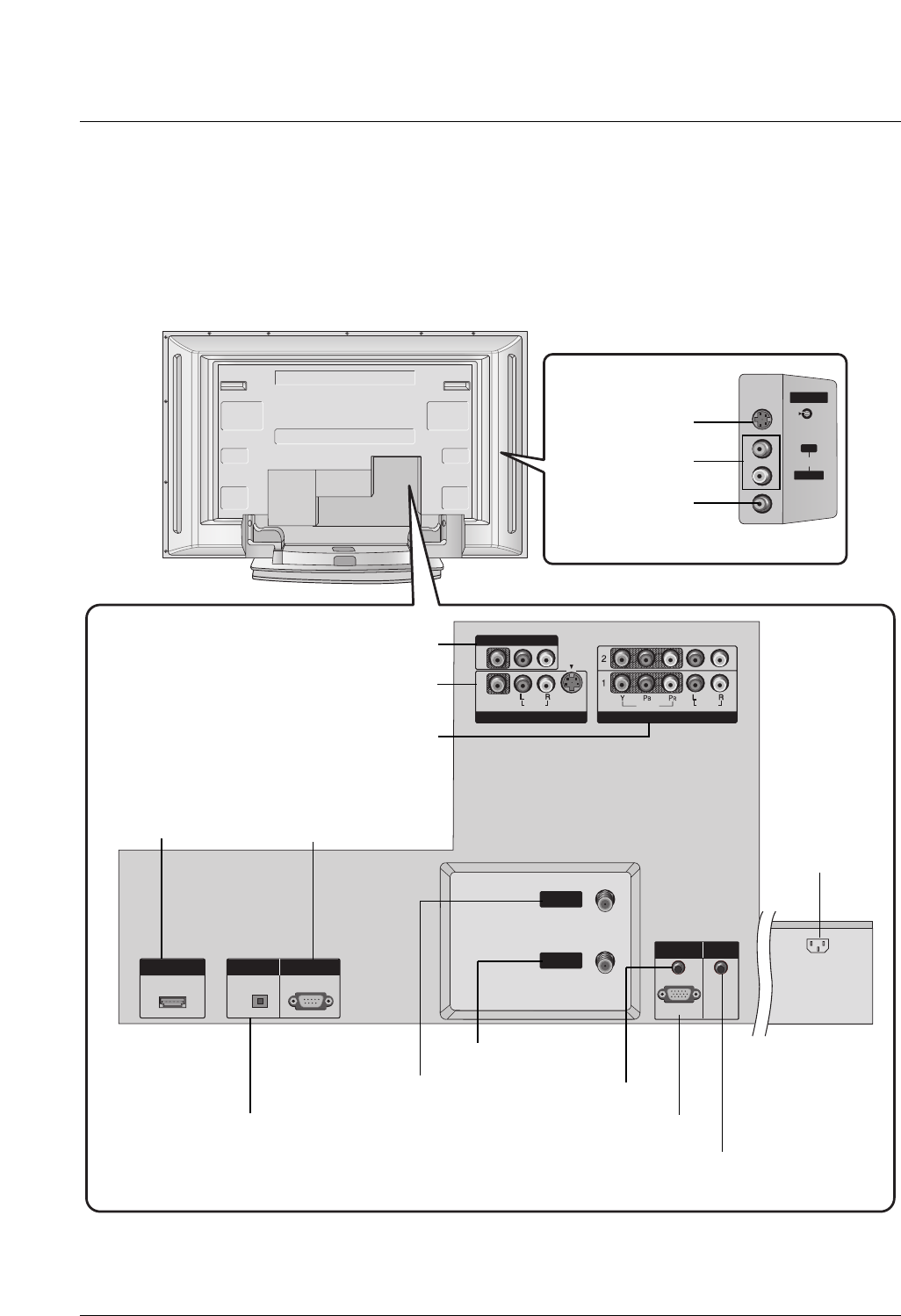
- Here shown may be somewhat different from your TV.
AUDIO Input
S-VIDEO Input
VIDEO Input
DIGITAL AUDIO OUT
OPTICAL
AV OUT
AV IN1
COMPONENT IN 1/2
HDMI/DVI IN
ANTENNA IN
CABLE IN
AUDIO (RGB/DVI)
RGB (PC/DTV)
AC IN
RS-232C INPUT
(Control &Service)
REMOTE CONTROL Port
12
Introduction
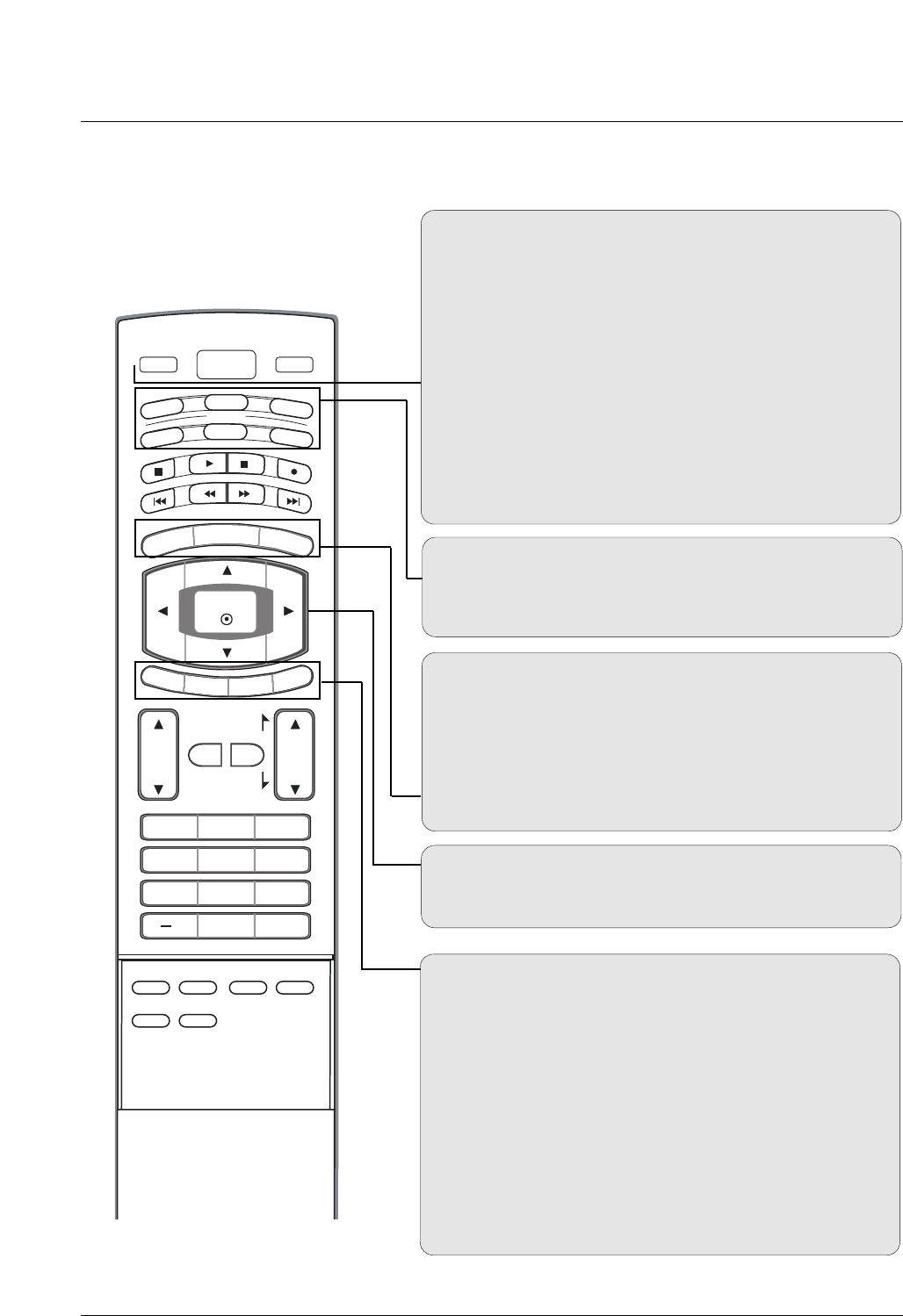
Remote Control Key Functions
Remote Control Key Functions
POWER
Turns your TV or any other programmed equipment on or
off, depending on mode.
VOL
CH
POWER
1 2 3
4 5 6
78
0
9
MENU
MUTE FAV
DAY -
GUIDE
DAY+
RATIO
VCR
TV
DVD
ENTER
APM
ADJUST
SAP
EZ SOUND
EZ PIC
FREEZE
FLASHBK
PA G E
PA G E
EXIT
TIMER
CC
INFO
AUDIO
CABLE
STB
MODE
TV INPUT INPUT
TV INPUT
Rotates the input mode between Antenna and Cable. In AV1-
2, Component 1-2, RGB-DTV (or RGB-PC), and HDMI/DVI
input sources, screen returns to the last TV channel.
MODE
Selects the remote operating mode: TV, DVD, VCR, AUDIO,
CABLE, or STB. Select a mode other than TV, for the remote
to operate an external device.
INPUT (Refer to p.14)
External input modes rotate in regular sequence: Antenna,
Cable, AV1-2, Component 1-2, RGB-DTV (or RGB-PC),
HDMI/DVI). (AV1, AV2,Component 1-2 input sources are linked
automatically, Only if these are connected)
EXIT
Clears all on-screen displays and returns to TV viewing from
any menu.
TIMER (Refer to p.45)
Lets you select the amount of time before your TV turns
itself off automatically.
CC (Refer to p.49)
Select a closed caption: Off, CC1~4, Text1~4.
MENU
Brings up the main menu to the screen.
GUIDE (Refer to p.16)
Shows program schedule.
RATIO (Refer to p.47)
Changes the aspect ratio.
THUMBSTICK (Up/Down/Left/Right/ENTER)
Allows you to navigate the on-screen menus and adjust the
system settings to your preference.
INFO (Refer to p.15)
When you watch the TV, information displays on top of the
screen. Not available in Component 1-2, RGB and HDMI/DVI
mode.
13
Introduction
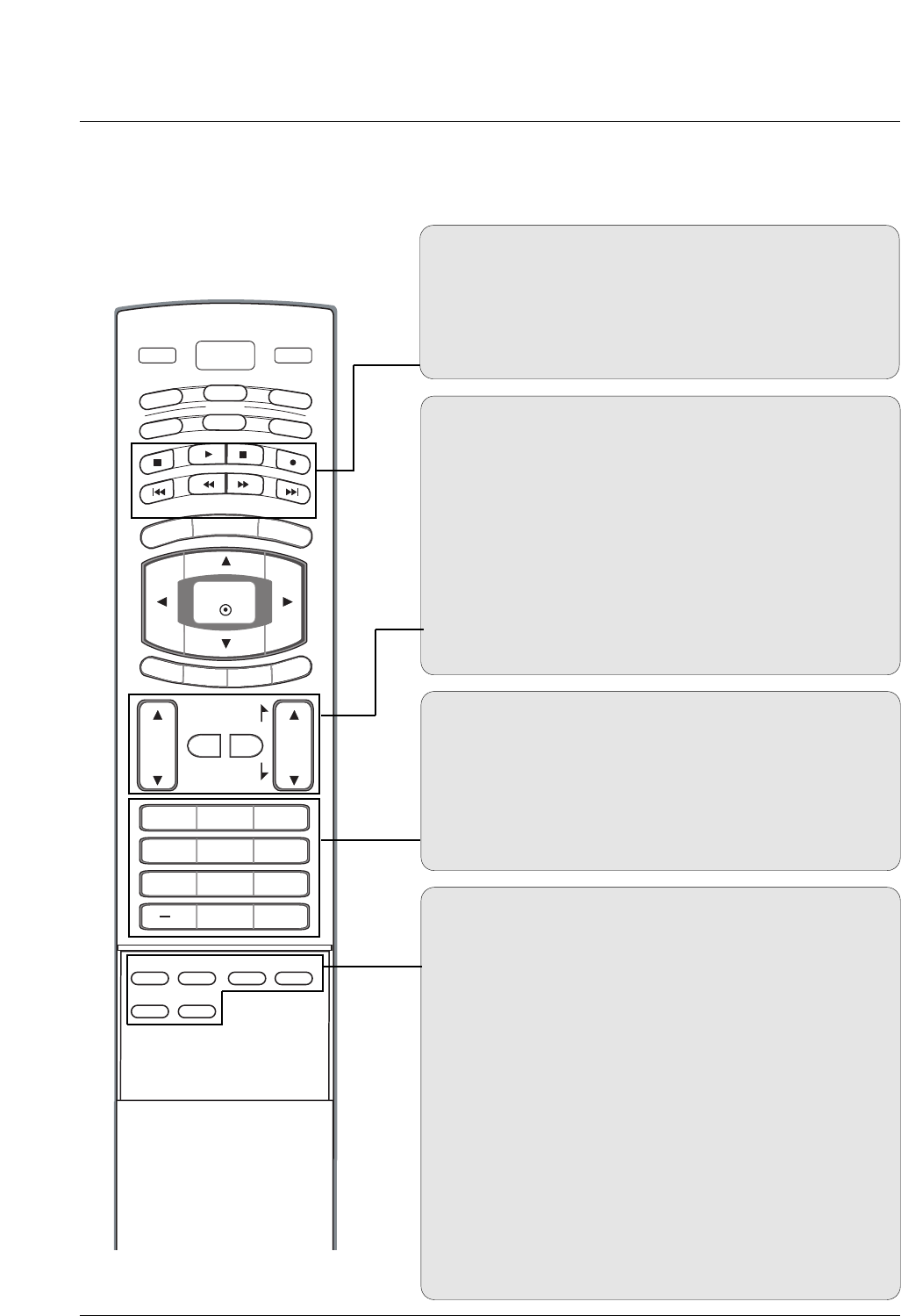
EZ PIC (Refer to p.38)
Selects a factory preset picture mode depending on the view-
ing environment.
EZ SOUND (Refer to p.41)
Selects the sound appropriate for the program's character.
SAP (Refer to p.42)
Selects MTS sound: Mono, Stereo, and SAP in analog mode.
Change the audio language in DTV mode.
FREEZE
Freezes the currently-viewed picture.
ADJUST (Refer to p.31)
Adjusts screen position, size, and phase in PC mode.
APM (Refer to p.38)
Concurrently, compare with the Daylight, Normal, Night Time
and Custom on the screen.
FAV
Use to scroll the Favorite channels.
MUTE
Switches the sound on or off.
CHANNEL UP/DOWN
Selects available channels found with EZ scan and Manual scan.
PAGE UP/DOWN
Moves from one full set of screen information to the next one.
VOLUME UP/DOWN
Increases/decreases the sound level.
VOL
CH
POWER
1 2 3
4 5 6
78
0
9
MENU
MUTE FAV
DAY -
GUIDE
DAY+
RATIO
VCR
TV
DVD
ENTER
APM
ADJUST
SAP
EZ SOUND
EZ PIC
FREEZE
FLASHBK
PA G E
PA G E
EXIT
TIMER
CC
INFO
AUDIO
CABLE
STB
MODE
TV INPUT INPUT
— (DASH)
Used to enter a program number for multiple program chan-
nels such as 2-1, 2-2,etc.
NUMBER BUTTONS
FLASHBK
Returns to the last channel viewed.
VCR/DVD/DVHS/Camcorder BUTTONS
Control some video cassette recorders or DVD players
("RECORD" button is not available for DVD player).
DAY + / DAY-
Moves forward or backward in 24 hour increments.
14
Introduction
VOL
CH
POWER
1 2 3
4 5 6
78
0
9
MENU
MUTE FAV
DAY -
GUIDE
DAY+
RATIO
VCR
TV
DVD
ENTER
APM
ADJUST
SAP
EZ SOUND
EZ PIC
FREEZE
FLASHBK
PA G E
PA G E
EXIT
TIMER
CC
INFO
AUDIO
CABLE
STB
MODE
TV INPUT INPUT
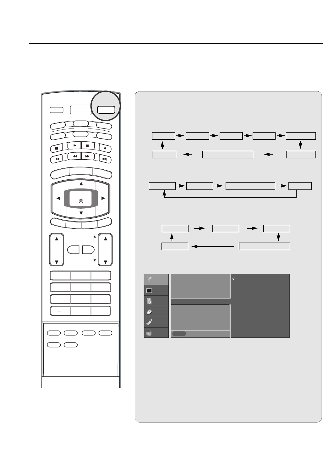
1. When every external equipment is connected:
2. When no external equipment is connected:
Auto Link
Auto Link
Antenna AV1 AV2Cable Component1
HDMI/DVI Component2RGB-DTV (or RGB-PC)
3. When some External Equipment is connected:
(ex: When connected to AV IN1)
RGB-DTV (or RGB-PC)
AV1
HDMI/DVI
Antenna Cable
Antenna Cable RGB-DTV (or RGB-PC) HDMI/DVI
• You can also select Input Source in the SETUP menu.
• Antenna: Select it when watching the TV/DTV.
• Cable: Select it when watching the CATV/CADTV.
• AV 1 , AV 2 : Select it when watching the VCR or external equip-
ment.
• Component 1-2: Select it when using a DVD or Digital set-top
box depend on connector.
• RGB-PC / RGB-DTV: Select it when using PC or Digital set-top
box depend on connector.
• HDMI / DVI: Select it when using DVD, PC or Digital set-top
box depend on connector.
INPUT
Previous
MENU
EZ Scan
Manual Scan
Channel Edit
DTV Signal
Input Source G
Input Label
Set ID
Antenna
Cable
AV1
AV2
Component1
Component2
RGB-PC
HDMI/DVI
SETUP
VIDEO
AUDIO
TIME
OPTION
LOCK
15
Introduction
VOL
CH
POWER
1 2 3
4 5 6
78
0
9
MENU
MUTE FAV
DAY -
GUIDE
DAY+
RATIO
VCR
TV
DVD
ENTER
APM
ADJUST
SAP
EZ SOUND
EZ PIC
FREEZE
FLASHBK
PA G E
PA G E
EXIT
TIMER
CC
INFO
AUDIO
CABLE
STB
MODE
TV INPUT INPUT
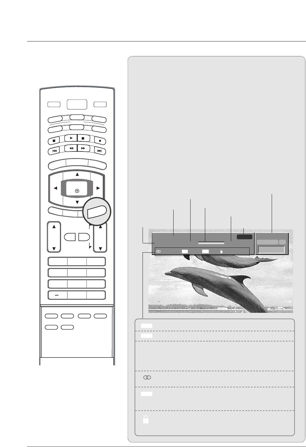
Brief Info.
Brief Info.
What is Brief Info?
: Brief Info shows the present screen information.
How to use?
1. Press the INFO button to show the Brief Info on the screen.
2. Press the INFO button or EXIT button to exit.
- The INFO button does not work in Component1,
Component2, RGB, and HDMI/DVI modes.
This function works in the following mode:
• Watching TV/DTV/CATV/CADTV
• Watching AV1, AV2
Brief Info Title Test Brief Info Title Test Brief Inf..
SAT, Jan 20, 2005 7:00PM
Multilingual
Caption 1080i TV-PG D L S V
6:55AM
DTV 2-1
CC 4:3
Program title
Program start time Banner information
Program progress bar
Program finish time
Present time
Day of week
Month, Year
The original aspect ratio of the video is 4:3
The original aspect ratio of the video is 16:9 (wide)
The video resolution is 720x480i
The video resolution is 720x480p
The video resolution is 1280x720p
The video resolution is 1920x1080i
Multilingual: The program contains two or more audio
services. Press the SAP button to select wanted Audio.
Caption: The program contains one or more caption ser-
vices. Press the CC button to select wanted Closed cap-
tion.
V-Chip: The program contains V-Chip information. Refer
to the LOCK menu: A (Age), D (Dialogue), L (Language), S
(Sex), V (Violence), FV (Fantasy Violence)
16 : 9
4 : 3
CC
480i
480p
720p
1080i
ABCDEFGHIJ...
10:40AM
Dolby Digital HD
INFO
16
Introduction
VOL
CH
POWER
1 2 3
4 5 6
78
0
9
MENU
MUTE FAV
DAY -
GUIDE
DAY+
RATIO
VCR
TV
DVD
ENTER
FLASHBK
PA G E
PA G E
EXIT
TIMER
CC
INFO
AUDIO
CABLE
STB
MODE
TV INPUT INPUT
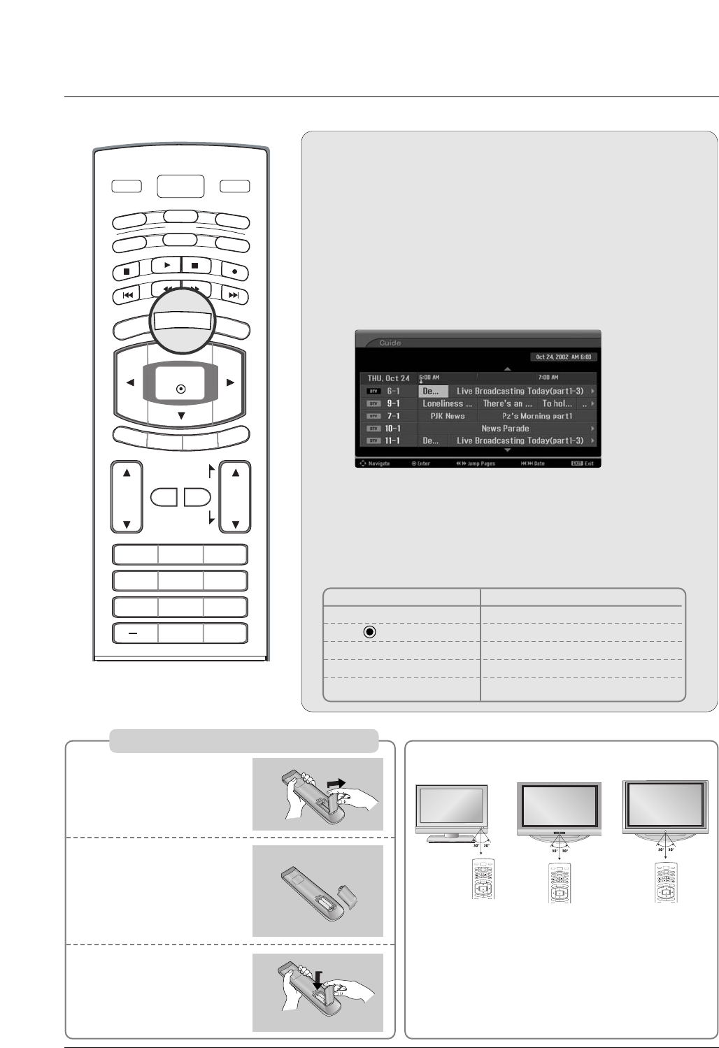
EPG (Electronic Program Guide)
EPG (Electronic Program Guide)
(In DTV mode)
(In DTV mode)
- This system has an Electronic Program Guide (EPG) to help
your navigate through all the possible viewing options.
- The EPG supplies information such as program listings, start
and end times for all available services.
- This function can be used only when the EPG information is
broadcasted by broadcasting companies.
- The EPG displays the program description for next 3 days.
- This function is only supported in DTV mode.
Press the GUIDE button to switch on EPG.
Press the DD / EE/ FF / GGbutton to select desired program, then
press the ENTER button to display the selected program.
Press the GUIDE or EXIT button again to switch off EPG and
return to TV viewing.
1
2
3
Remote Control Buttons Function
D / E / F / GSelect the desired program
Change to the selected channel
FF / GG Jump Page
IFF / GGIChange the date
GUIDE/EXIT Switch off EPG
GUIDE
Installing Batteries
Open the battery com-
partment cover on the
back side.
Insert two batteries in
correct polarity (+ with
+, - with -). Don’t mix
old or used batteries
with new ones.
Close the cover.
* Use a remote control 7 meter distance and 30
degree (left/right) within the receiving unit scope.
* Dispose of used batteries in a recycle bin to prevent
environmental hazards.
POWER
MENU
DAY -
GUIDE
DAY+
RATIO
VCR
TV
DVD
ENTER
EXIT
TIMER
CC
INFO
AUDIO
CABLE
STB
MODE
TV INPUT INPUT
POWER
MENU
DAY -
GUIDE
DAY+
RATIO
VCR
TV
DVD
ENTER
EXIT
TIMER
CC
INFO
AUDIO
CABLE
STB
MODE
TV INPUT INPUT
1
2
3
32/37/42LC2D**
42/50PC3D**
POWER
MENU
DAY -
GUIDE
DAY+
RATIO
VCR
TV
DVD
ENTER
EXIT
TIMER
CC
INFO
AUDIO
CABLE
STB
MODE
TV INPUT INPUT
42PC1D**
17
Installation
Installation
Installation
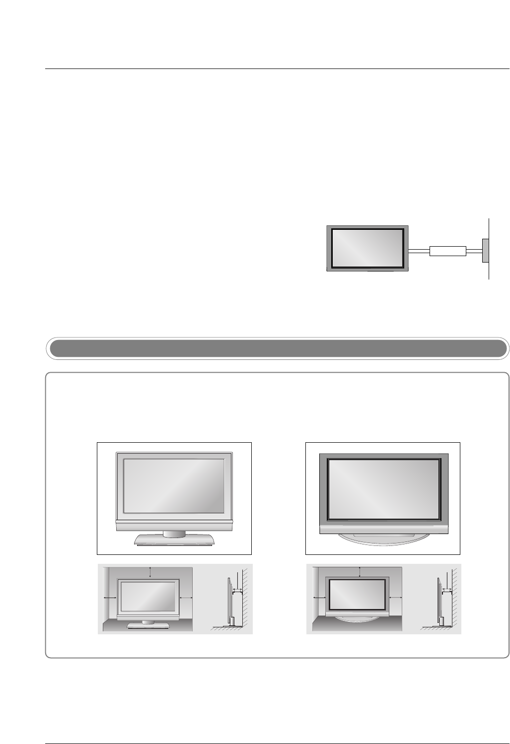
Desktop Pedestal Installation
4 inches 4 inches
4 inches
4 inches
4 inches 4 inches
4 inches4 inches
For proper ventilation, allow a clearance of 4" on each side and from the wall.
GROUNDING
Ensure that you connect the earth ground wire to prevent pos-
sible electric shock. If grounding methods are not possible,
have a qualified electrician install a separate circuit breaker.
Do not try to ground the unit by connecting it to telephone
wires, lightening rods, or gas pipes.
Power
Supply
Short-circuit
Breaker
•The TV can be installed in various ways such as on a wall, or on a desktop etc.
•The TV is designed to be mounted horizontally.
Various Installation
32/37/42LC2D** 42PC1D**, 42PC3D**, 50PC3D**
18
Installation
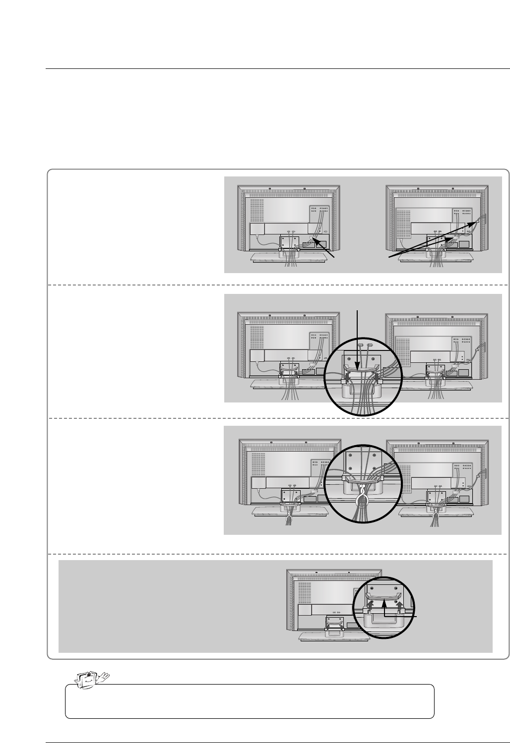
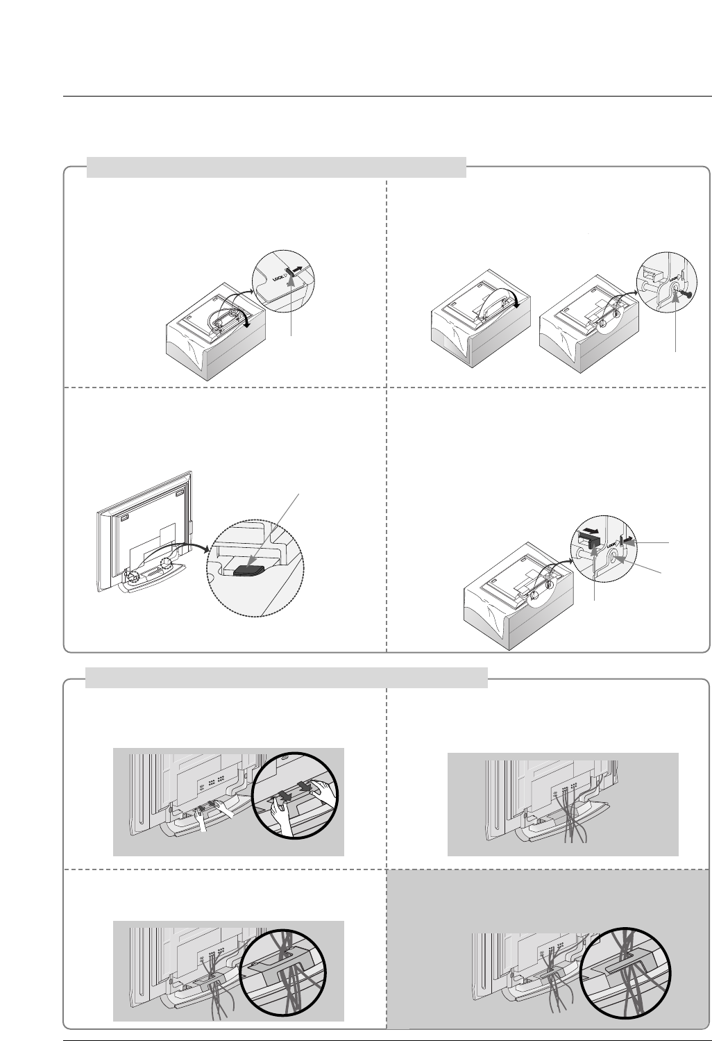
Connect the cables as necessary.
After connecting the cables neat-
ly, arrange the cables to the
Cable Holder.
To connect an additional equip-
ment, see the External equip-
ment Connections section.
Reinstall the CABLE MANAGE-
MENT as shown.
1
2
Bundle the cables using the sup-
plied twister holder.
3
Basic Connection (For 32/37/42LC2D**)
Basic Connection (For 32/37/42LC2D**)
Installation
Installation
32LC2D**
Cable holder
37/42LC2D**
32LC2D** 37/42LC2D**
32LC2D** 37/42LC2D**
Do not hold the CABLE MANAGEMENT when moving the product.
- If the product is dropped, you may be injured or the product may be broken.
How to remove
the CABLE MANAGEMENT
- Hold the CABLE MANAGEMENT with both hands
and pull it upward.
CABLE
MANAGEMENT
CABLE MANAGEMENT
19
Installation
Place the set with the screen facing down on
a cushion or soft cloth as shown.
Before unfolding the stand, please make sure
two locks (A) on the bottom of the stand push
outward.
Pull the stand out as shown.
After unfolding the stand, please insert and
tighten the screws (provided as parts of the
product) in the holes (B) on the bottom of the
stand.
12
When connecting cables to the set, Do not
disengage the lock (C).
This may cause the set to fall, causing serious
bodily injury and serious damage to the set.
3
Basic Connection
Basic Connection
(C)
Hold the CABLE MANAGEMENT with both
hands and push it as shown.
Connect the cables as necessary.
To connect an additional equipment, see the
External equipment Connections section.
Reinstall the CABLE MANAGEMENT as
shown.
12
3
* Image shown here may be slightly different from
your set.
When closing the stand for storage
- First remove the screws in the holes (B) on the bottom
of the stand. And then pull two Hooks (D) of the stand
bottom and fold the stand into the back of the set.
- After folding, push the two Locks (A) of the stand
bottom outward.
(A)
(B)
(D)
(A)
(B)
How to use stand (For 42PC1D**, 42PC3D**)
How to arrange the cable (For 50PC3D**)
For 42PC1D**, 42PC3D**
Arrange the cable as shown.
20
Installation
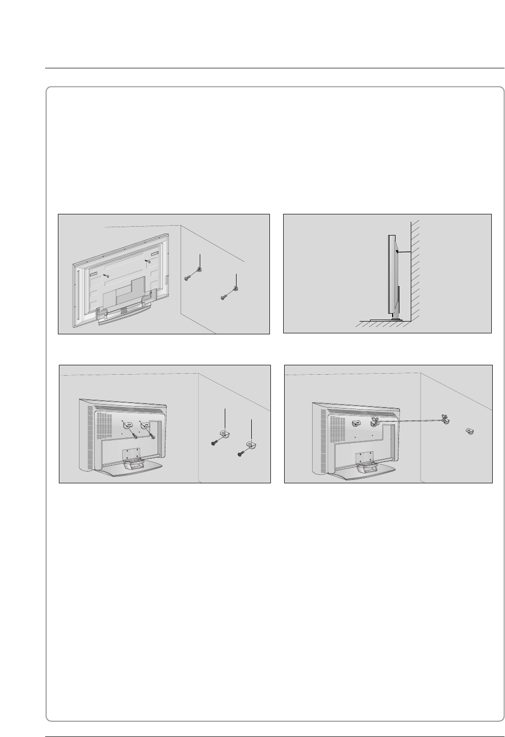
How to join the product assembly to the wall to protect the set tumbling
- Set it up close to the wall so the product doesn’t fall over when it is pushed backwards.
- The instructions shown below is a safer way to set up the product, which is to fix it on the wall so the prod-
uct doesn’t fall over when it is pulled in the forward direction. It will prevent the product from falling for-
ward and causing injury. It will also prevent the product from damage caused by fall. Please make sure
that children don’t climb on or hang from the product.
42PC1D**/42PC3D**/50PC3D**
Notes
•When moving the product to another place undo the ropes first.
•Use a product holder or a cabinet that is big and strong enough for the size and weight of the product.
•To use the product safely make sure that the height of the bracket that is mounted on the wall is same
as that of the product.
2
2
3
1
1
3
Use the eye-bolts or TV brackets/bolts to fix the product to the wall as shown in the picture.
(If your product has the bolts in the eye-bolts position , loosen the bolts.)
* Insert the eye-bolts or TV brackets/bolts and tighten them securely in the upper holes.
Secure the wall brackets with the bolts (not provided as parts of the product, must purchase separately)
on the wall. Match the height of the bracket that is mounted on the wall.
Use a sturdy rope (not provided as parts of the product, must purchase separately) to tie the product.
It is safer to tie the rope so it becomes horizontal between the wall and the product.
1
2
3
32/37/42LC2D**
21
Installation
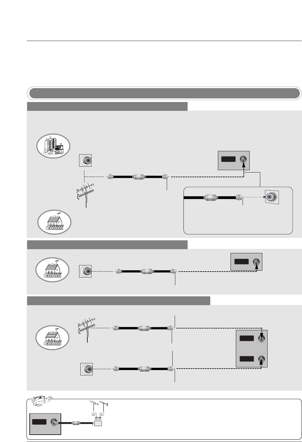
Antenna or Cable Connection
Multi-family Dwellings/Apartments
(Connect to wall antenna socket)
Single-family Dwellings /Houses
(Connect to wall jack for outdoor antenna)
Outdoor Antenna
Wall Antenna Socket
VHF Antenna
UHF Antenna
RF Coaxial Wire (75 ohm)
Turn clockwise to tighten.
AV IN 2
L/MONO
R
AUDIO
S-VIDEO
VIDEO
L/MONO
R
AUDIO
S-VIDEO
VIDEO
AV IN 2
HDMI/DVI IN
DIGITAL AUDIO
OUT
OPTICAL
RS-232C IN
(CONTROL
&
SERVICE)
VIDEO
AUDIO
( )
VIDEO
AUDIO
COMPONENT IN
S-VIDEO
AV IN 1
AV OUT
ANTENNAANTENNA
ININ
CABLE
IN
RGB (PC/DTV)
RGB IN
AUDIO (RGB/DVI)
REMOTE
CONTROL IN
Bronze Wire
Be careful not to bend the bronze wire when
connecting the antenna.
Analog and Digital TV signals provided on antenna
- Antenna or Cable Service without a Cable Box Connection.
- For optimum picture quality, adjust antenna direction if needed.
Cable TV Wall Jack
RF Coaxial Wire (75 ohm)
Turn clockwise to tighten.
Analog and Digital TV signals provided on cable
Analog and Digital TV signals provided on cable and antenna
Cable TV Wall Jack
RF Coaxial Wire (75 ohm)
Bronze Wire
Bronze Wire
Turn clockwise to tighten.
Antenna
RF Coaxial Wire (75 ohm)
•In a poor signal area to improve picture quality, purchase and install a sig-
nal amplifier.
•If the antenna needs to be split for two TV’s, install a “2-Way Signal Splitter”
in the connections.
•If the antenna is not installed properly, contact your dealer for assistance.
AV IN 2
L/MONO
R
AUDIO
S-VIDEO
VIDEO
L/MONO
R
AUDIO
S-VIDEO
VIDEO
AV IN 2
HDMI/DVI IN
DIGITAL AUDIO
OUT
OPTICAL
RS-232C IN
(CONTROL
&
SERVICE)
VIDEO
AUDIO
( )
VIDEO
AUDIO
COMPONENT IN
S-VIDEO
AV IN 1
AV OUT
ANTENNAANTENNA
ININ
CABLE
IN
RGB (PC/DTV)
RGB IN
AUDIO (RGB/DVI)
REMOTE
CONTROL IN
External Equipment Connections
External Equipment Connections
signal
amplifier
AV IN 2
L/MONO
R
AUDIO
S-VIDEO
VIDEO
L/MONO
R
AUDIO
S-VIDEO
VIDEO
AV IN 2
HDMI/DVI IN
DIGITAL AUDIO
OUT
OPTICAL
RS-232C IN
(CONTROL
&
SERVICE)
VIDEO
AUDIO
( )
VIDEO
AUDIO
COMPONENT IN
S-VIDEO
AV IN 1
AV OUT
ANTENNA
IN
CABLECABLE
ININ
RGB (PC/DTV)
RGB IN
AUDIO (RGB/DVI)
REMOTE
CONTROL IN
AV IN 2
L/MONO
R
AUDIO
S-VIDEO
VIDEO
L/MONO
R
AUDIO
S-VIDEO
VIDEO
AV IN 2
HDMI/DVI IN
DIGITAL AUDIO
OUT
OPTICAL
RS-232C IN
(CONTROL
&
SERVICE)
VIDEO
AUDIO
( )
VIDEO
AUDIO
COMPONENT IN
S-VIDEO
AV IN 1
AV OUT
ANTENNA
ANTENNA
IN
IN
CABLE
CABLE
IN
IN
RGB (PC/DTV)
RGB IN
AUDIO (RGB/DVI)
REMOTE
CONTROL IN
NOTE: All cables shown are not included with the TV
22
Installation
- To avoid picture noise (interference), leave an adequate distance between the VCR and TV.
- Typically a frozen still picture from a VCR. If the 4:3 picture format is used; the fixed images on the sides
of the screen may remain visible on the screen.
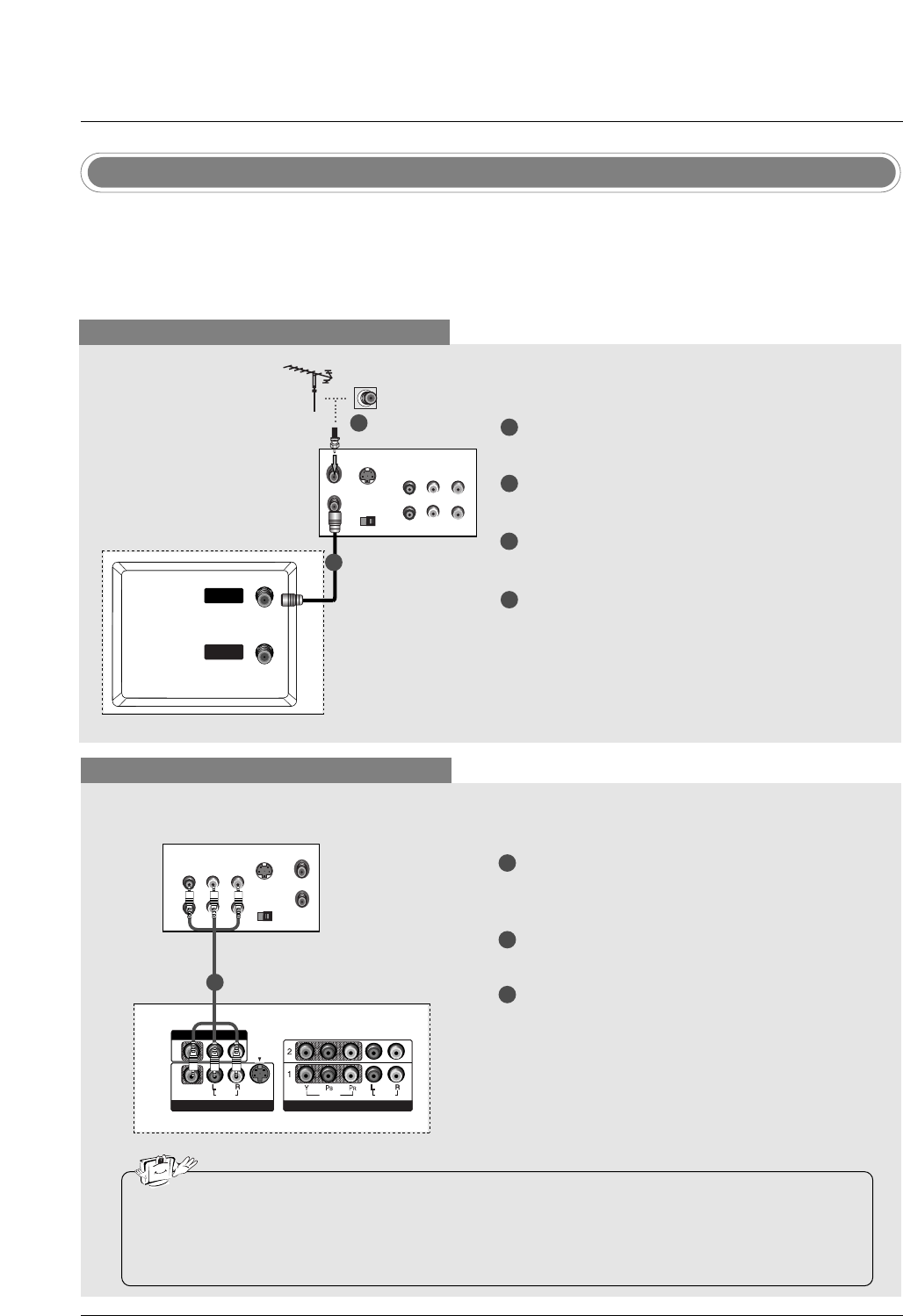
VCR Setup
When connecting with an antenna
S-VIDEO OUT
IN
(R) AUDIO (L) VIDEO
34
OUTPUT
SWITCH
ANT OUT
ANT IN
VIDEO
AUDIO
( )
VIDEO
AUDIO
COMPONENT IN
S-VIDEO
AV IN 1
AV OUT
ANTENNAANTENNA
IN
CABLECABLE
IN
VIDEO
AUDIO
( )
VIDEO
AUDIO
COMPONENT IN
S-VIDEO
AV IN 1
AV OUT
When connecting with a RCA cable
S-VIDEO
OUT
IN
(R) AUDIO (L) VIDEO
34
OUTPUT
SWITCH
ANT OUT
ANT IN
VIDEO
AUDIO
MONO
( )
VIDEO
AUDIO
COMPONENT IN
S-VIDEO
AV IN 1V IN 1
AV OUTV OUT
ANTENNA
IN
CABLE
IN
VIDEO
AUDIO
( )
VIDEO
AUDIO
COMPONENT IN
S-VIDEO
AV IN 1
AV OUT
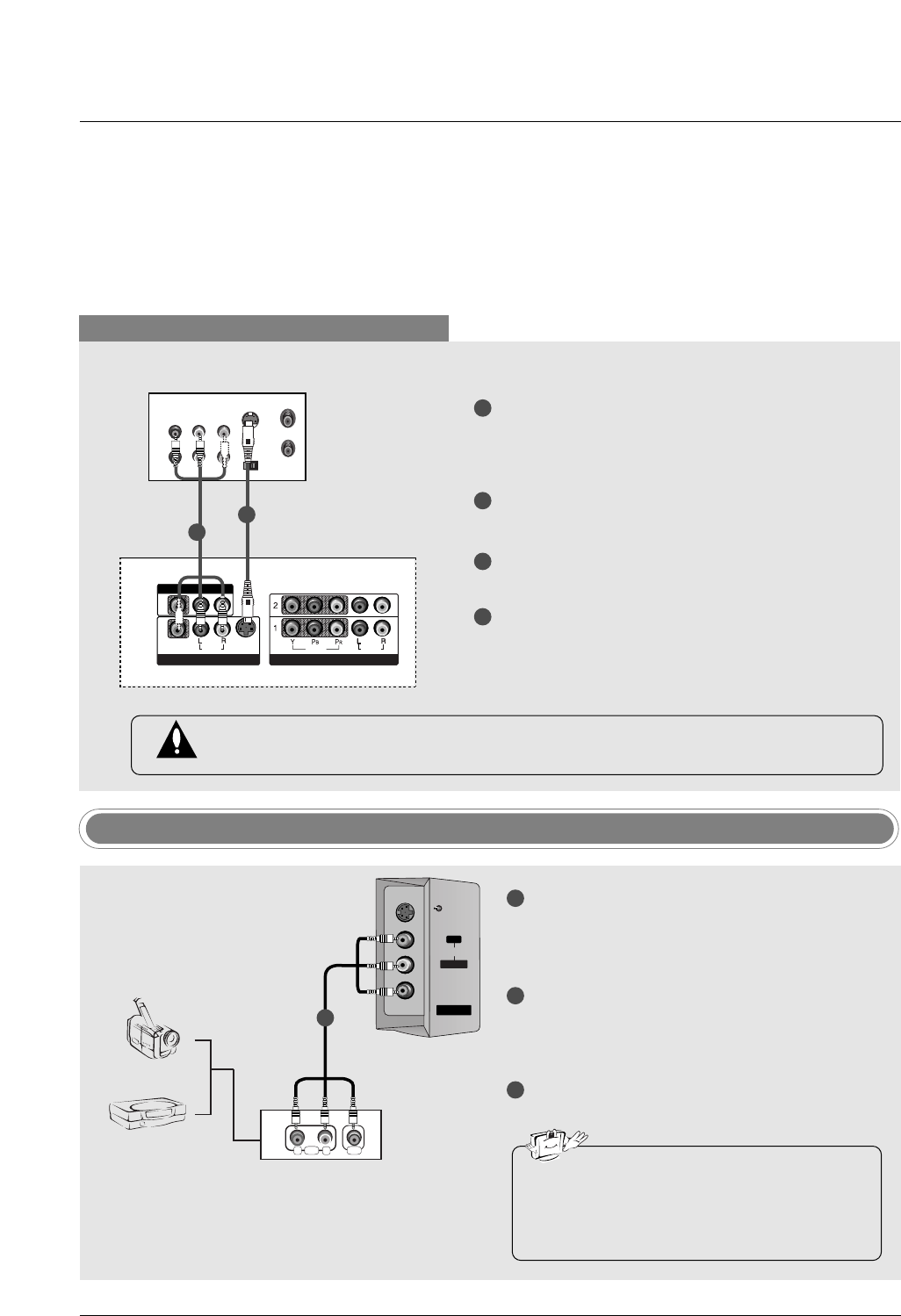
VCR
1
2
3
Connect the AUDIO/VIDEO jacks between TV
and VCR. Match the jack colors (Video = yellow,
Audio Left = white, and Audio Right = red)
Insert a video tape into the VCR and press PLAY
on the VCR. (Refer to the VCR owner’s manual.)
Select AV1 input source using the INPUT button
on the remote control.
- If connected to AV IN2, select AV2 input source.
•If you have a mono VCR, connect the audio cable from the VCR to the AUDIO L/MONO jack of the
set.
•This TV finds the connected input sources automatically for AV1, AV2 and Component 1-2. It is pre-
sumed that RGB and HDMI/DVI sources are connected.
1
1
2
3
4
Connect the RF antenna out socket of the VCR to
the Antenna socket on the set.
Connect the antenna cable to the RF antenna in
socket of the VCR.
Set VCR output switch to 3 or 4 and then tune TV
to the same channel number.
Insert a video tape into the VCR and press PLAY
on the VCR. (Refer to the VCR owner’s manual.)
VCR
1
2
23
Installation
When connecting with an S-Video cable
S-VIDEO
OUT
IN
(R) AUDIO (L) VIDEO
34
OUTPUT
SWITCH
ANT OUT
ANT IN
VIDEO
AUDIO
( )
VIDEO
AUDIO
COMPONENT IN
S-VIDEO
AV IN 1
AV OUT
ANTENNA
IN
CABLE
IN
VIDEO
AUDIO
MONO
( )
VIDEO
AUDIO
COMPONENT IN
S-VIDEO
AV IN 1V IN 1
AV OUTV OUT
VCR
1
1
2
2
3
4
Connect the S-VIDEO output of the VCR to the S-
VIDEO input on the set. The picture quality is
improved; compared to normal composite (RCA
cable) input.
Connect the audio outputs of the VCR to the
AUDIO input jacks on the set.
Insert a video tape into the VCR and press PLAY
on the VCR. (Refer to the VCR owner’s manual.)
Select AV1 input source with using the INPUT
button on the remote control.
- If connected to AV IN2, select AV2 input source.
Do not connect to both Video and S-Video at the same time. In the event that you connect
both Video and the S-Video cables, only the S-Video will work.
RL
AUDIO VIDEO
AV IN 2
V IN 2
L/MONO
MONO
R
AUDIO
AUDIO
S-VIDEO
S-VIDEO
VIDEO
VIDEO
Camcorder
Video Game Set
1
1
2
3
Connect the AUDIO/VIDEO jacks between TV
and external equipment. Match the jack colors
(Video = yellow, Audio Left = white, and Audio
Right = red).
Select AV2 input source with using the INPUT
button on the remote control.
- If connected to AV IN1 input, select AV1 input
source.
Operate the corresponding external equipment.
Refer to external equipment operating guide.
External AV Source Setup
•This TV finds the connected input sources
automatically for AV1, AV2 and Component 1-
2. It is presumed that RGB and HDMI/DVI
sources are connected.
i.e) 32LC2D**
24
Installation
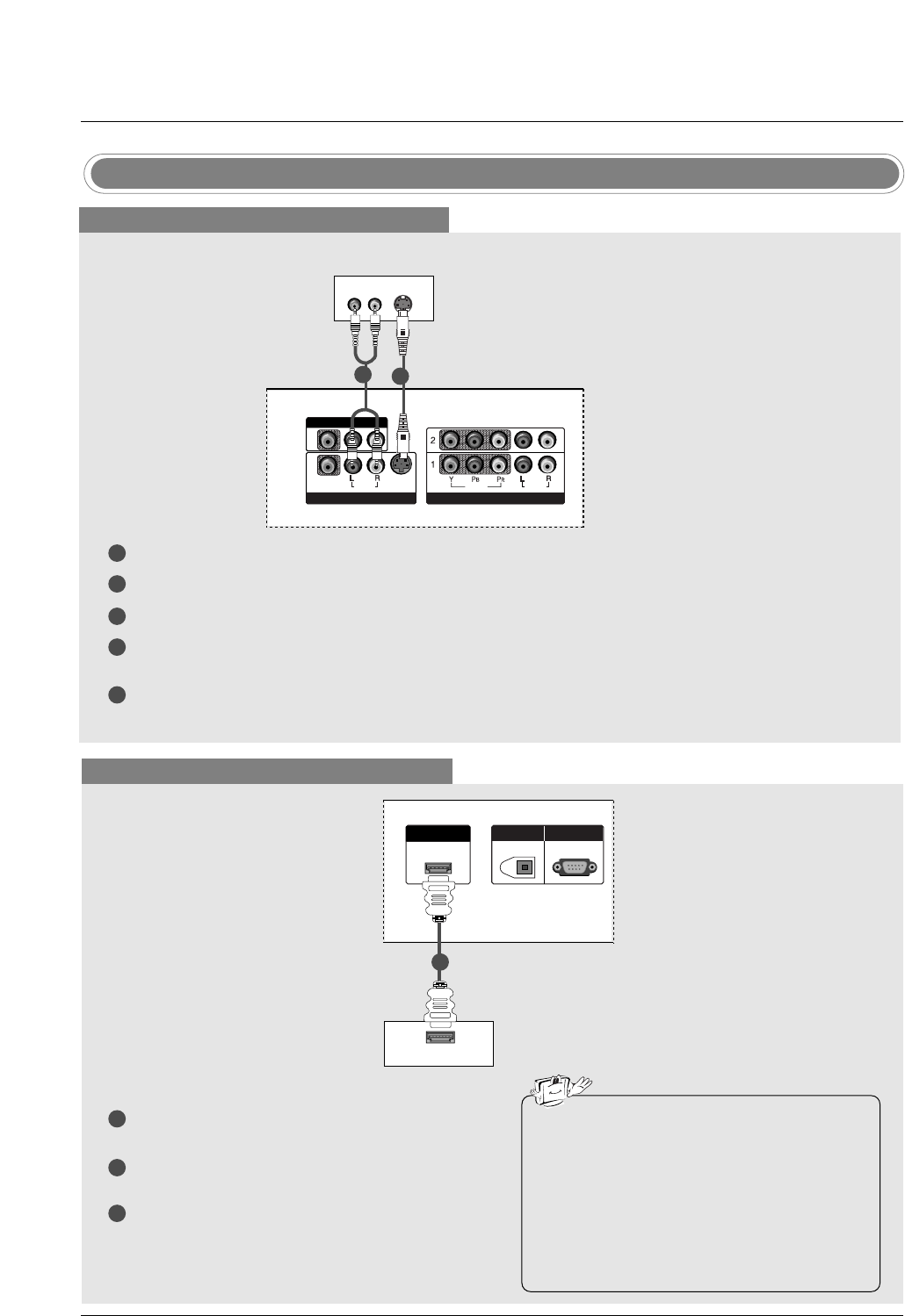
DVD Setup
When connecting with a S-Video cable
S-VIDEO
(R) AUDIO (L)
VIDEO
AUDIO
( )
VIDEO
AUDIO
COMPONENT IN
S-VIDEO
AV IN 1
AV OUT
VIDEOVIDEO
AUDIOUDIO
MONO
( )
VIDEOVIDEO
AUDIOUDIO
COMPONENT INCOMPONENT IN
S-VIDEOS-VIDEO
AV IN 1V IN 1
AV OUTV OUT
HDMI/DVI IN
DIGITAL AUDIO
OUT
OPTICAL
RS-232C IN
(CONTROL
&
SERVICE)
DVD
1
1
2
2
3
4
5
Connect the S-VIDEO output of the DVD to the S-VIDEO input on the set.
Connect the audio outputs of the DVD to the AUDIO input jacks on the set.
Turn on the DVD player, insert a DVD.
Select AV1 input source with using the INPUT button on the remote control.
- If connected to AV IN2, select AV 2 input source.
Refer to the DVD player's manual for operating instructions.
When connecting with a HDMI cable
1
2
3
Connect the HDMI output of the DVD to the
HDMI/DVI IN jack on the set.
Select HDMI/DVI input source with using the
INPUT button on the remote control.
Refer to the DVD player's manual for operating
instructions.
VIDEO
AUDIO
( )
VIDEO
AUDIO
COMPONENT IN
S-VIDEO
AV IN 1
AV OUT
VIDEO
AUDIO
( )
VIDEO
AUDIO
COMPONENT IN
S-VIDEO
AV IN 1
AV OUT
HDMI-DVD OUTPUT
HDMI/DVI IN
DIGITDIGITAL AAL AUDIO UDIO
OUTOUT
OPTICAL
RS-232C INRS-232C IN
(CONTROLOL
&
SERVICE)
DVD
1
•TV can receive the video and audio signal
simultaneously by using a HDMI cable.
•If the DVD supports Auto HDMI function, the
DVD output resolution will be automatically
set to 1280x720p.
•If the DVD does not support Auto HDMI, you
need to set the output resolution appropriate-
ly. To get the best picture quality, adjust the
output resolution of the DVD to 1280x720p.
25
Installation
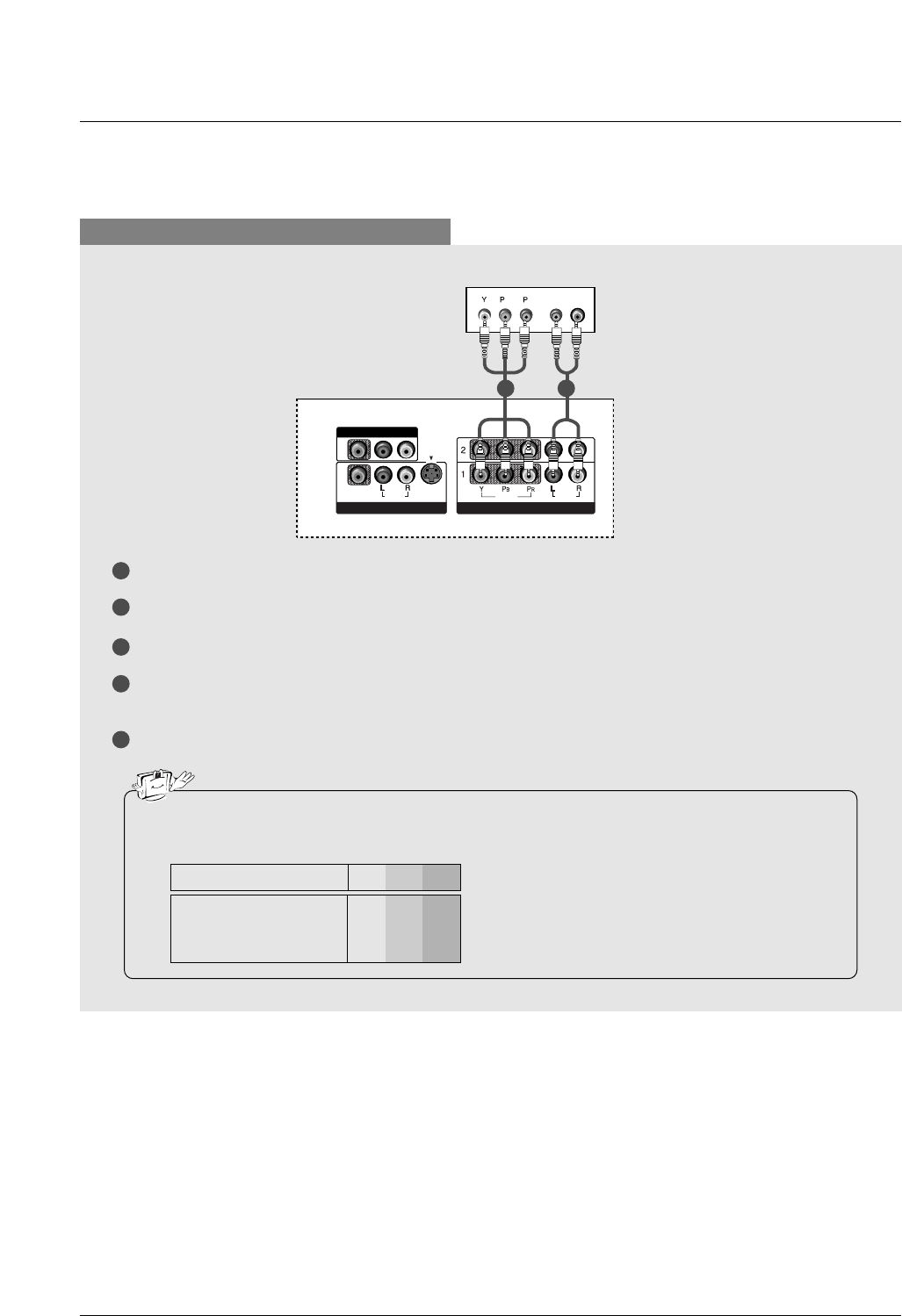
When connecting with a component cable
1
2
3
4
5
Connect the video outputs (Y, PB, PR) of the DVD to the COMPONENT IN VIDEO jacks on the set.
Connect the audio outputs of the DVD to the COMPONENT IN AUDIO jacks on the set.
Turn on the DVD player, insert a DVD.
Select Component 1 input source with using the INPUT button on the remote control.
- If connected to COMPONENT 2, select Component 2 input source.
Refer to the DVD player's manual for operating instructions.
•Component Input ports
To get better picture quality, connect a DVD player to the component input ports as shown below.
Y PBPR
Component ports on the TV
Y
Y
Y
Y
Pb
B-Y
Cb
PB
Pr
R-Y
Cr
PR
Video output ports
on DVD player
BR
(R) AUDIO (L)
VIDEOVIDEO
AUDIOUDIO
MONO
( )
VIDEOVIDEO
AUDIOUDIO
COMPONENT INCOMPONENT IN
S-VIDEOS-VIDEO
AV IN 1V IN 1
AV OUTV OUT
VIDEO
AUDIO
( )
VIDEO
AUDIO
COMPONENT IN
S-VIDEO
AV IN 1
AV OUT
HDMI/DVI IN
DIGITAL AUDIO
OUT
OPTICAL
RS-232C IN
(CONTROL
&
SERVICE)
DVD
1 2