LG Electronics USA 50PM4MAWA PLASMA MONITOR User Manual MFL36274107 en rev04
LG Electronics USA PLASMA MONITOR MFL36274107 en rev04
User manual
Please read this manual carefully before operating your set.
Retain it for future reference.
Record model number and serial number of the set.
See the label attached on the back cover and quote
this information to your dealer
when you require service.
OWNER’S MANUAL
PLASMA
MONITOR
MODELS: 42PM4M / 42PM4MA
50PM4M / 50PM4MA
60PM4M / 60PM4MA
P/NO: MFL36274107 (0803-REV04)
Printed in Korea
1
WARNING / CAUTION
WARNING / CAUTION
To prevent fire or shock hazards, do not expose
this product to rain or moisture.
FCC NOTICE
Class B digital device
This equipment has been tested and found to comply
with the limits for a Class B digital device, pursuant to
Part 15 of the FCC Rules. These limits are designed
to provide reasonable protection against harmful
interference in a residential installation. This equipment
generates, uses and can radiate radio frequency energy
and, if not installed and used in accordance with the
instructions, may cause harmful interference to radio
communications. However, there is no guarantee that
interference will not occur in a particular installation.
If this equipment does cause harmful interference to
radio or television reception, which can be determined
by turning the equipment off and on, the user is
encouraged to try to correct the interference by one
or more of the following measures:
- Reorient or relocate the receiving antenna.
- Increase the separation between the equipment and
receiver.
- Connect the equipment to an outlet on a circuit
different from that to which the receiver is connected.
- Consult the dealer or an experienced radio/TV
technician for help.
Any changes or modifications not expressly approved
by the party responsible for compliance could void
the user’s authority to operate the equipment.
CAUTION
Do not attempt to modify this product in any way
without written authorization from LG Electronics.
Unauthorized modification could void the user’s
authority to operate this product
The lightning flash with arrowhead
symbol, within an equilateral triangle, is
intended to alert the user to the presence
of uninsulated “dangerous voltage” within the
product’s enclosure that may be of sufficient
magnitude to constitute a risk of electric shock to
persons.
The exclamation point within an equilateral
triangle is intended to alert the user to
the presence of important operating and
maintenance (servicing) instructions in the litera-
ture accompanying the appliance.
TO REDUCE THE RISK OF ELECTRIC SHOCK
DO NOT REMOVE COVER (OR BACK). NO
USER SERVICEABLE PARTS INSIDE. REFER TO
QUALIFIED SERVICE PERSONNEL.
WARNING/CAUTION
TO REDUCE THE RISK OF FIRE AND ELECTRIC
SHOCK, DO NOT EXPOSE THIS PRODUCT TO
RAIN OR MOISTURE.
NOTE TO CABLE/TV INSTALLER
This reminder is provided to call the CATV system
installer’s attention to Article 820-40 of the National
Electric Code (U.S.A.). The code provides guidelines for
proper grounding and, in particular, specifies that the
cable ground shall be connected to the grounding system
of the building, as close to the point of the cable entry
as practical.
2Plasma Monitor
Safety Instructions
WARNING/CAUTION
TO REDUCE THE RISK OF FIRE AND ELECTRIC SHOCK, DO NOT EXPOSE THIS PRODUCT TO
RAIN OR MOISTURE.
Do not place the set in direct sunlight or near heat sources such as electric or gas heaters, a stove and so on.
-This may cause a fire.
Do not use the set in a damp place such as a bathroom or any place where it is likely to get wet.
- This may cause a fire or could give you an electric shock.
Bend the antenna cable between the inside and the outside of the building to prevent rain from flowing in.
-This may cause water damaged inside the set and could give you an electric shock.
Earth wire should be connected.
- If the earth wire is not connected, there is possibility of electric shock caused by the leakage current.
- If grounding methods are not possible, a separate circuit breaker should be employed and installed by a qualified electrician.
- Do not connect ground to telephone wires, lightning rods or a gas pipe.
Do not place anything containing liquid on top of the set.
- This may cause a fire or could give an electric shock.
Do not insert any object into the air exhaust vents.
- This may cause a fire or could give you an electric shock.
Do not place heavy objects on the set.
- This may cause serious injury to a child or adult.
Do not use water while cleaning the set.
- This may cause damage to the set or could give an electric shock.
In case of smoke or a strange smell from the set, switch it off ,unplug it from the wall outlet and contact your deal-
er or service centre.
- This may cause a fire or could give you an electric shock.
Do not attempt to service the set yourself. Contact your dealer or service centre.
- This may cause damage to the set or could give you an electric shock.
During a lightning or thunder storm, unplug the set from the wall outlet and don’t touch the antenna cable.
- This may cause damage to the set or could give you an electric shock.
WARNING
Safety Instructions
Safety Instructions
Owner’s Manual 3
ENGLISH
Safety Instructions
Never touch the power plug with a wet hand.
- This may cause an electric shock.
Disconnect the unit from the mains power and remove all connections before moving the unit.
Do not place the set in a built-in installation such as a bookcase or rack.
- Ventilation is required for the unit.
When installing the set on a table, be careful not to place the edge of its stand.
- This may cause the set to fall, causing serious injury to a child or adult, and serious damage to the set.
Do not place an outside antenna in the vicinity of overhead power lines or other electric light or power circuits.
- This may cause an electric shock.
There should be enough distance between an outside antenna and power lines to keep the former from touching the
latter even when the antenna falls.
- This may cause an electric shock.
Do not pull the cord but the plug when unplugging.
- This may cause a fire.
Ensure the power cord doesn’t trail across any hot objects like a heater.
- This may cause a fire or an electric shock.
Do not plug when the power cord or the plug is damaged or the connecting part of the power outlet is loose.
- This may cause a fire or an electric shock.
Dispose of used batteries carefully to protect a child from eating them.
- In case that someone eats them, take the person to see a doctor immediately..
When moving the set assembled with speakers do not carry holding the speakers.
- This may cause the set to fall, causing serious injury to a child or adult, and serious damage to the monitor.
Unplug this product from the wall outlet before cleaning. Do not use liquid cleaners or aerosol cleaners.
- This may cause damage to the set or could give an electric shock.
Contact the service center once a year to clean the internal part of the set.
- Accumulated dust can cause mechanical failure.
The distance between eyes and the screen should be about 5 ~ 7 times as long as diagonal length of the screen.
- If not, you may strain your eyes.
Unplug the set from the wall outlet when it is left unattended and unused for long periods of time.
- Accumulated dust may cause a fire or an electric shock from
deterioration or electric leakage.
NOTES
*Safety instructions have two kinds of information, and each meaning of it is as below.
Take care of danger that may happen under specific condition.
The violation of this instruction may cause serious injuries and even death.
The violation of this instruction may cause light injuries or damage of the
product.
WARNING
NOTES
4Plasma Monitor
Safety Instructions
Safety Instructions continued
Safety Instructions continued
CAUTION concerning the Power Cord :
-Most appliances recommend they be connected to a dedicated circuit; that is,
a single outlet circuit which powers only that appliance and has no additional
outlets or branch circuits.
- This may cause a fire or an electric shock.
-Do not overload wall outlets. Overloaded wall outlets, loose or damaged wall outlets, extension cords, frayed power cords,
or damaged or cracked wire insulation are dangerous. Any of these conditions could result in electric shock or fire.
Periodically examine the cord of your appliance, and if its appearance indicates damage or deterioration, unplug it, discon-
tinue use of the appliance, and have the cord replaced with an exact replacement part by an authorized service centre.
-Protect the power cord from physical or mechanical abuse, such as being twisted, kinked, pinched, closed in a door, or walked
upon. Pay particular attention to plugs, wall outlets, and the point where the cord exits the appliance.
-Use a dedicated power cord. Do not modify or extend the power cord.
- Do not install, remove, or reinstall the unit by yourself (customer).
For electrical work, contact the dealer, seller, a qualified electrician, or an Authorized Service Center. For installation, always
contact the dealer or an Authorized Service Center.
- Do not use if the power cord or plug is damaged, or socket is loose. Use a dedicated outlet for this appliance.
-Do not over bend the power cord and do not place anything on the power cord. Do not install the monitor near any sharp
edge to avoid wire damage.
Outdoor Use Marking :
- WARNING - To Reduce The Risk Of Fire Or Electric Shock, Do Not Expose This Appliance To Rain Or Moisture.
Wet Location Marking :
-Apparatus shall not be exposed to dripping or splashing and no objects filled with liquids, such as vases, shall be placed on
the apparatus.

Owner’s Manual 5
ENGLISH
Contents
Safety Instructions . . . . . . . . . . . . . . . . . . . . . . . . . . . . .2~4
Introduction
Accessories . . . . . . . . . . . . . . . . . . . . . . . . . . . .7
Controls and Connection Options . . . . . . . . . .8~9
Remote Control Key Functions . . . . . . . . . . . . .10
Installation
Installation Instructions . . . . . . . . . . . . . . . . . . . . .11
External Equipment Connections . . . . . . . . . .12~16
When Connecting to your PC . . . . . . . . . . .12~13
Watching RGB Outputs . . . . . . . . . . . . . . . . . . .13
When watching VCR / DVD . . . . . . . . . . . . . . .14
When watching HDTV/DVD(480p/576p/
720p/1080i/480i/576i) . . . . . . . . . . . . . . . . . . .15
When watching HDMI/DVI/RGB
from the VCR/DVD/Set-top Box
(480p/576p/720p/1080i) . . . . . . . . . . . . . . . . . .15
Watching AV Outputs . . . . . . . . . . . . . . . . . . . .16
Operation
Turning on the Monitor . . . . . . . . . . . . . . . . . . . . .17
Menu Language Selection . . . . . . . . . . . . . . . . . .17
Picture Menu Options
PSM (Picture Status Memory) . . . . . . . . . . . . . .18
Manual Picture Control (user option) . . . . . . . . .18
CSM (Colour Status Memory) . . . . . . . . . . . . . .18
Manual Colour Temperature Control . . . . . . . . .19
XD . . . . . . . . . . . . . . . . . . . . . . . . . . . . . . . . . .19
Advanced - Cinema . . . . . . . . . . . . . . . . . . . . .20
Advanced - Black level . . . . . . . . . . . . . . . . . . .20
Reset . . . . . . . . . . . . . . . . . . . . . . . . . . . . . . . .20
Sound Menu Options
SSM . . . . . . . . . . . . . . . . . . . . . . . . . . . . . . . . .21
AVL (Auto Volume Leveler) . . . . . . . . . . . . . . . .21
Balance . . . . . . . . . . . . . . . . . . . . . . . . . . . . . .22
Speaker . . . . . . . . . . . . . . . . . . . . . . . . . . . . . .22
Timer Menu Options
Clock Setup . . . . . . . . . . . . . . . . . . . . . . . . . . .23
On/Off Time Setup . . . . . . . . . . . . . . . . . . . . . .23
Auto sleep . . . . . . . . . . . . . . . . . . . . . . . . . . . .24
Special Menu Options
Child Lock . . . . . . . . . . . . . . . . . . . . . . . . . . . .25
ISM (Image Sticking Minimization) Method . . . .25
Tile mode . . . . . . . . . . . . . . . . . . . . . . . . . .26~27
Low Power . . . . . . . . . . . . . . . . . . . . . . . . . . . .27
XD DEMO . . . . . . . . . . . . . . . . . . . . . . . . . . . .28
Screen Menu Options
Auto Configure . . . . . . . . . . . . . . . . . . . . . . . . .29
Manual Configure . . . . . . . . . . . . . . . . . . . . . . .29
Selecting XGA mode . . . . . . . . . . . . . . . . . . . . .30
Setting the Picture Format . . . . . . . . . . . . . . . .30
Initializing (Reset to original factory settings) . . .31
External Control Device Setup . . . . . . . . . . . . .32~37
IR Code . . . . . . . . . . . . . . . . . . . . . . . . . . . . . . . .38~39
Troubleshooting Checklist . . . . . . . . . . . . . . . . . . .40
Product Specifications . . . . . . . . . . . . . . . . . . . . . . .41
Contents
Contents
After reading this manual, keep it handy for future reference.

6Plasma Monitor
Introduction
Introduction
Introduction
What is a Plasma Display Panel?
If voltage is applied to a gas within glass panels, ultraviolet rays are produced and fused with a fluorescent substance. At that
instant, light is emitted. A Plasma Display is the a next generation flat Display using this phenomenon.
160° - Wide angle range of vision
Your flat panel plasma screen offers an exceptionally broad viewing angle -- over 160 degrees. This means that the display is
clear and visible to viewers anywhere in the room.
Wide Screen
The screen of the Plasma Display is 42",50" or 60" so wide that your viewing experience is as if you are in a movie theater.
Versatile
The light weight and thin size makes it easy to install your plasma display in a variety of locations where conventional TVs would
not fit.
The Plasma Monitor Manufacturing Process: Why minute colored dots may be present on the Plasma
Monitor screen
The Plasma Display Panel which is the display device of this product is composed of 0.9 to 2.2 million cells. A few cell defects will
normally occur in the Plasma Monitor manufacturing process. Several minute colored dots visible on the screen should be accept-
able. This also occurs in other Plasma Monitor manufacturers' products and the tiny dots appearing does not mean that this
Plasma Monitor is defective. Thus a few cell defects are not sufficient cause for the Plasma Monitor to be exchanged or returned.
Our production technology is designed to minimize cell defects during the manufacture and operation of this product.
Cooling Fan Noise
In the same way that a fan is used in a PC computer to keep the CPU (Central Processing Unit) cool, the Plasma Monitor is
equipped with cooling fans to cool the Monitor and improve its reliability. Therefore, a certain level of noise could occur while the
fans are operating and cooling the Plasma Monitor.
The fan noise doesn't have any negative effect on the Plasma Monitor's efficiency or reliability. The noise from these fans is nor-
mal during the operation of this product. We hope you understand that a certain level of noise from the cooling fans is acceptable
and is not sufficient cause for the Plasma Monitor to be exchanged or returned.
WARNING
TO REDUCE THE RISK OF FIRE AND ELECTRIC SHOCK, DO NOT EXPOSE THIS PRODUCT TO
RAIN OR MOISTURE.
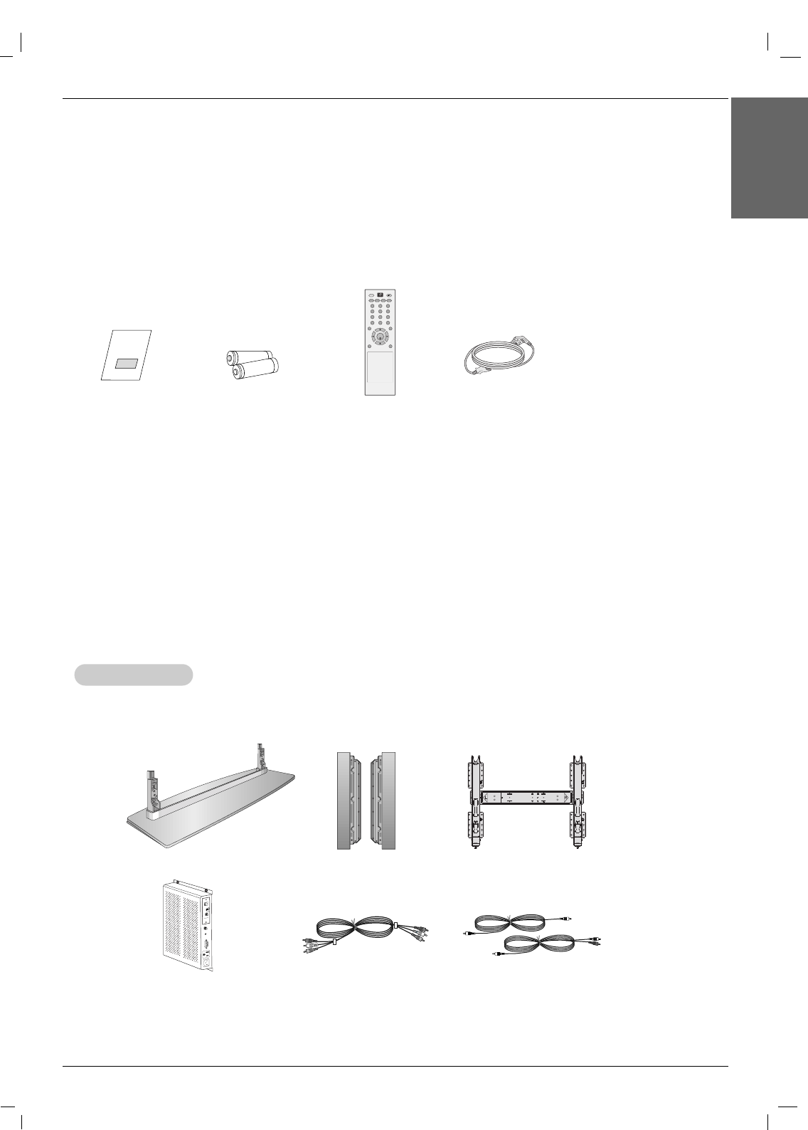
Ensure that the following accessories are included with your plasma display. If an accessory is missing, please contact the dealer
where you purchased the product.
Video cables
D-BOX
ANTENNA
CABLE
AC IN AC OUT
AUX
CONTROL
DISPLAY CONTROL
CABLE OUT
M.P.I.
Audio cables
-Optional extras can be changed or modified for quality improvement without any notification new optional extras can be added.
- Contract your dealer for buying these items.
Option Extras
Option Extras
Desktop stand speaker
Owner’s Manual 7
Introduction
ENGLISH
Accessories
Accessories
Owner’s Manual
1.5V
1.5V
Batteries Power Cord
AV
SLEEP PSM ARC AUTO
MENU EXIT
MUTE
*
POWER
1 2 3
4 5 6
7 8 9
0
INPUT
SET
Remote Control
Tilt wall mounting bracket
8Plasma Monitor
Introduction
Controls
Controls
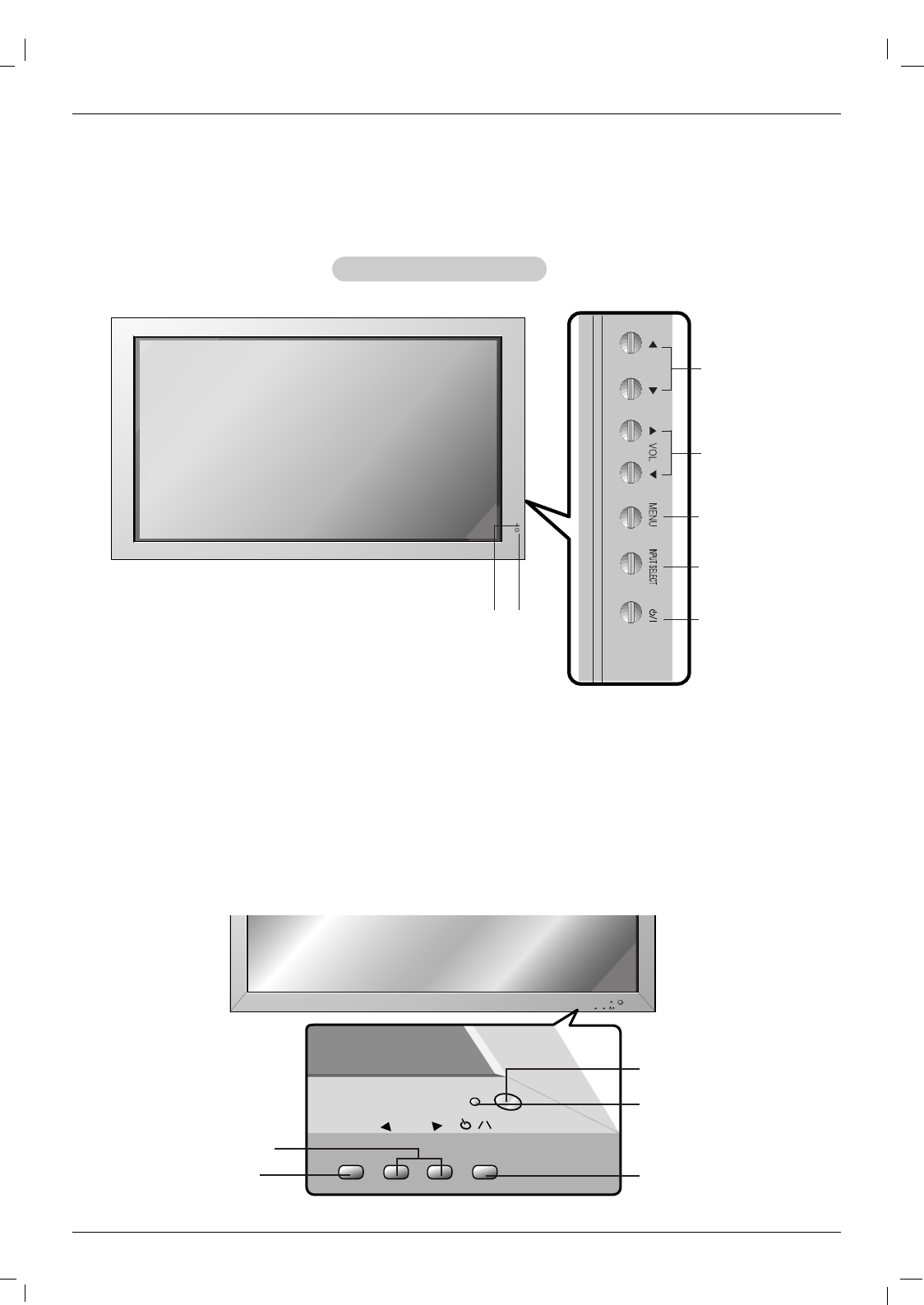
Front Panel Controls
Front Panel Controls
-Here shown may be somewhat different from your set.
1.Power Indicator
Illuminates red in standby mode, Illuminates green when the
Set is turned on.
2. Remote Control Sensor
3. FF ,GG Buttons
4. VOLUME (EE, DD) Buttons
5. MENU Button
6. INPUT SELECT Button
7. Main Power Button
Switches the set on from standby or off to standby.
2
1
4
3
5
6
7
60PM4M
INPUT
SELECT
VOLUME
INPUT
SELECT
VOLUME
INPUT SELECT Button
VOLUME (FF,GG) Buttons
Power Standby Indicator
Illuminates red in standby mode,
Illuminates green when the
Monitor is turned on
Remote Control Sensor
Sub power button
Owner’s Manual 9
Introduction
ENGLISH
Connection Options
Connection Options
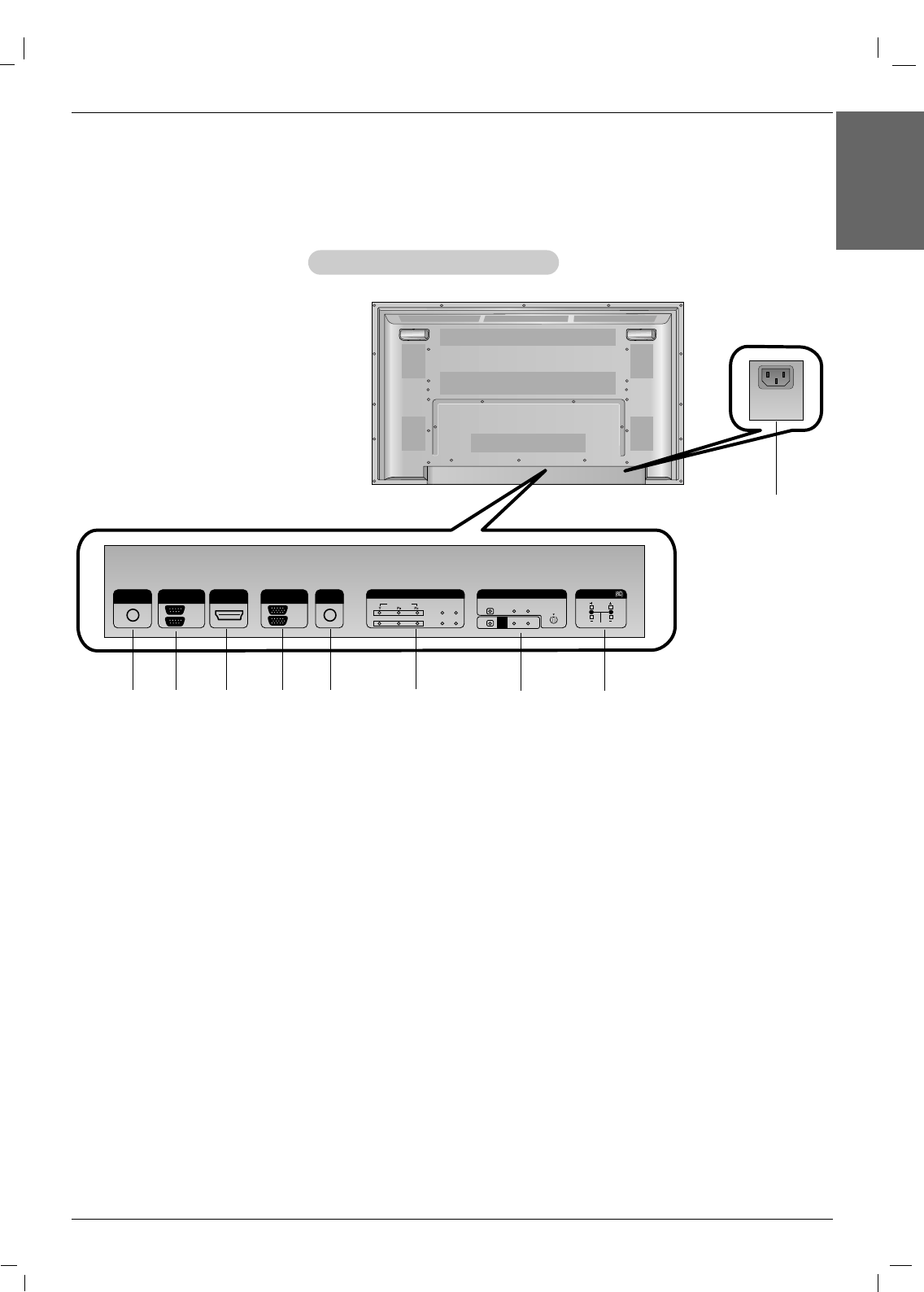
Back Connection Panel
Back Connection Panel
-Here shown may be somewhat different from your set.
REMOTE
CONTROL IN
AUDIO
(RGB/DVI)
HDMI/DVI IN
RL
RS-232C
(CONTROL&SERVICE)
OUT
IN
RGB
OUT
IN
COMPONENT IN
VIDEO
2
1
L-AUDIO-R
L-AUDIO-R S-VIDEO
AV IN
VIDEO
AV
OUT
EXTERNAL SPEAKER
AC IN
15
2 3 78
9
1. REMOTE CONTROL IN
2. RS-232C INPUT(CONTROL&SERVICE) PORT
OUT
For control the another set, connect a RS-232C Cable from
RS-232C out port to another set’s RS-232C input port.
IN
Connect to the RS-232C port on a PC.
3. HDMI/DVI IN
Connect a HDMI signal to this jack. Or connect a DVI(Video)
signal.
4. RGB INPUT
Connect the set output connector from a PC to the
appropriate input port.
RGB OUTPUT
You can watch the RGB signal on another set, connect RGB
OUTPUT to another set’s PC input port.
5. AUDIO (RGB/DVI)
Connect a PC Phone Cable.
6. COMPONENT INPUT 1-2
Connect a component video/audio device to these jacks.
7. AV IN
Connect audio/video output from an external device to these
jacks.
S-VIDEO
Connect S-Video out from an S-VIDEO device.
AV OUT
Connect a AV Cable from AV(CVBS) out port to another
set's AV input port.
8. EXTERNAL SPEAKER (8 ohm output)
Connect to optional external speaker(s).
* For further information, refer to ‘Speaker & Speaker
Stand’ manual.
9. POWER CORD SOCKET
This set operates on an AC power. The voltage is indicated on
the Specifications page. Never attempt to operate the set on
DC power.
46
10 Plasma Monitor
Introduction
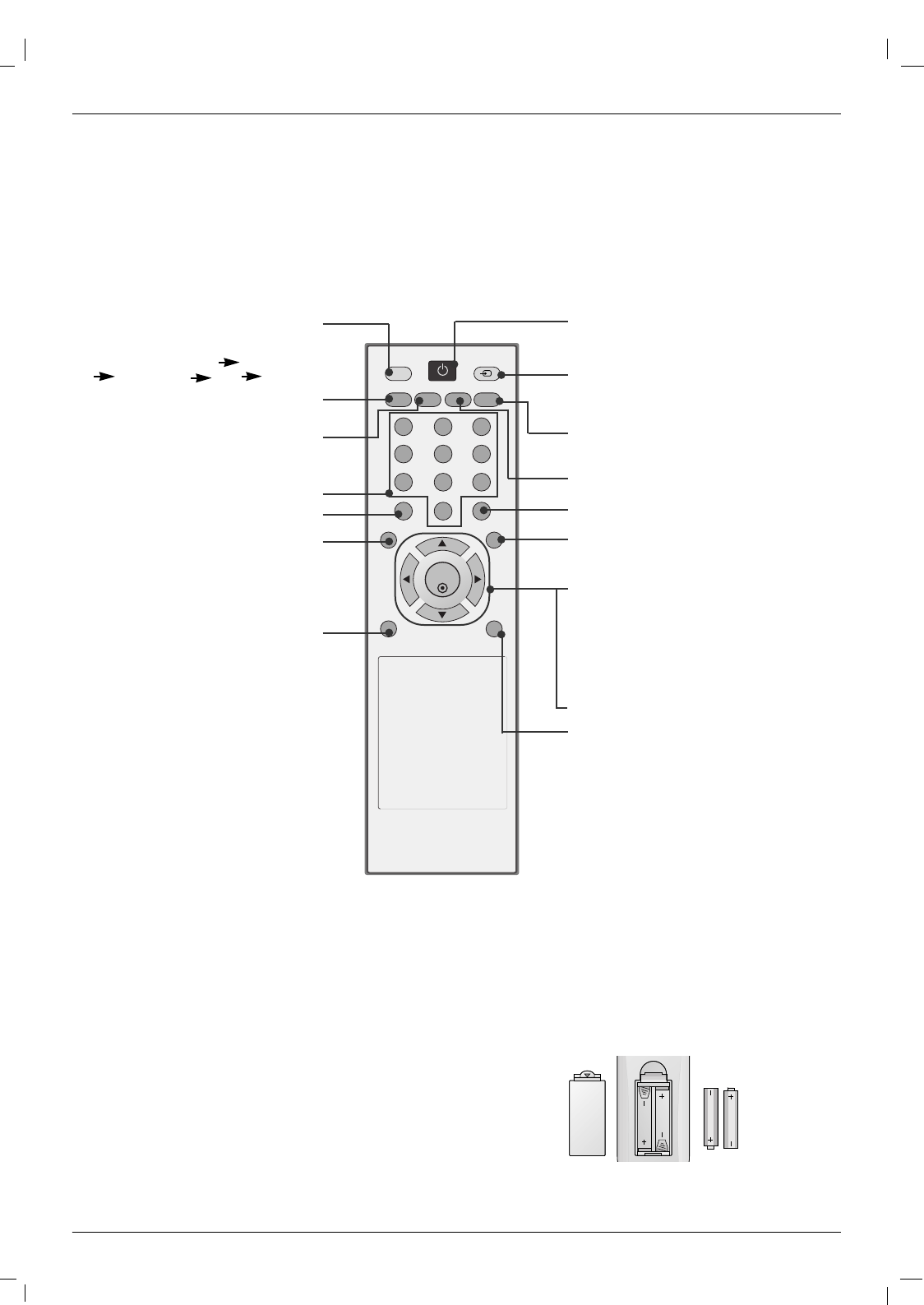
- When using the remote control, aim it at the remote control sensor on the monitor.
- Under certain conditions such as if the remote IR signal is interrupted, the remote control may not function. Press
the key again as necessary.
Remote Control Key Functions
Remote Control Key Functions
Installing Batteries
• Open the battery compartment cover on the back side and install the bat-
teries matching correct polarity (+ with +, - with -).
• Install two 1.5V AAA batteries. Don’t mix old or used batteries with new
ones. Replace cover.
AV
SLEEP PSM ARC AUTO
MENU EXIT
MUTE
*
POWER
1 2 3
4 5 6
7 8 9
0
INPUT
SET
POWER
switches the set on from standby or off to
standby.
INPUT
Selects the AV, Component, RGB or
HDMI/DVI modes.
switches the set on from standby.
EXIT
Clears all on-screen displays and returns
to
monitor
viewing from any menu.
There is not a function which is supported.
SET
accepts your selection or displays the
current mode.
FF/ GG
Volume Up/Down
DD/ EE
Adjusts menu settings.
Selects menu item.
*: No function
AUTO
Automatic adjustment function.
(Operational for the analog signal only)
ARC
Changes the picture format.
NUMBER buttons
There is not a function which is supported.
MENU
Displays on screen menus one by
one.
Exits the current menu.
Memorizes menu changes.
MUTE
Switches the sound on or off.
SLEEP
Sets the sleep timer.
PSM
Adjusts the factory preset picture
according to the room.
AV buttons
Each time you press the lnput but-
ton it will change to
AV Component1
Component2 RGB HDMI/DVI.
W
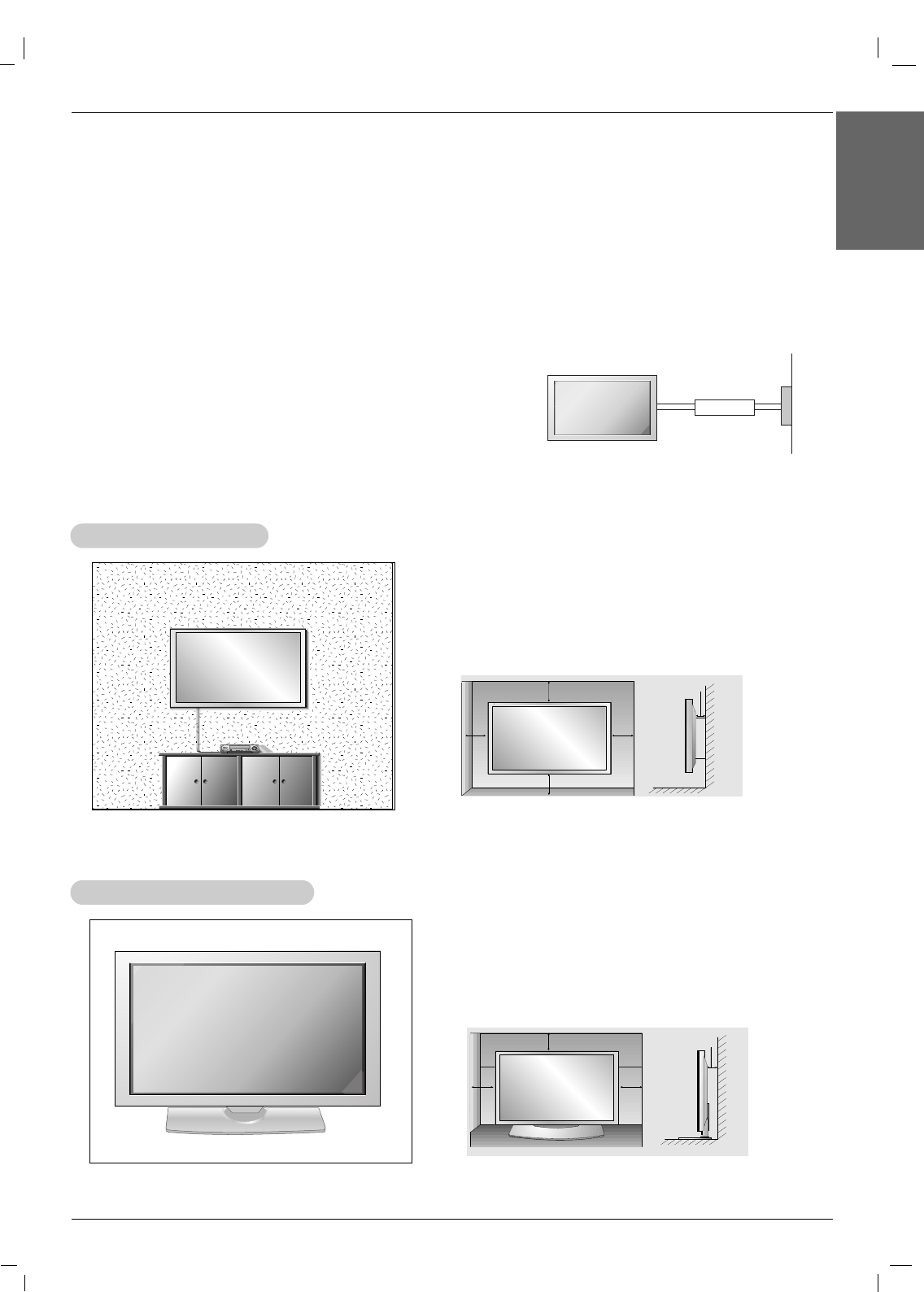
Wall Mount Installation
all Mount Installation
For proper ventilation, allow a clearance of 4” on each
side and 4” from the wall. Detailed installation instruc-
tions are available from your dealer, see the optional
Wall Mounting Bracket Installation and Setup Guide.
•Install this monitor only in a location where adequate ventilation is available.
• If set is installed vertically, it is on the control key toward down.
GROUNDING
Ensure that you connect the grounding / earth wire to prevent possible
electric shock. If grounding methods are not possible, have a qualified
electrician install a separate circuit breaker. Do not try to ground the
unit by connecting it to telephone wires, lightening rods, or gas pipes.
Power
Supply
Short-circuit
Breaker
Desktop Pedestal Installation
Desktop Pedestal Installation
For proper ventilation, allow a clearance of 4” on each
side and the top and 4” from the wall. Detailed installa-
tion instructions are included in the optional Desktop
Stand Installation and Setup Guide available from your
dealer.
Installation
Installation
Installation Instructions
Installation Instructions
Owner’s Manual 11
Installation
ENGLISH
4 inches
4 inches
4 inches
4 inches4 inches
4 inches4 inches
4 inches
4 inches
12 Plasma Monitor
Installation
External Equipment Connections
External Equipment Connections
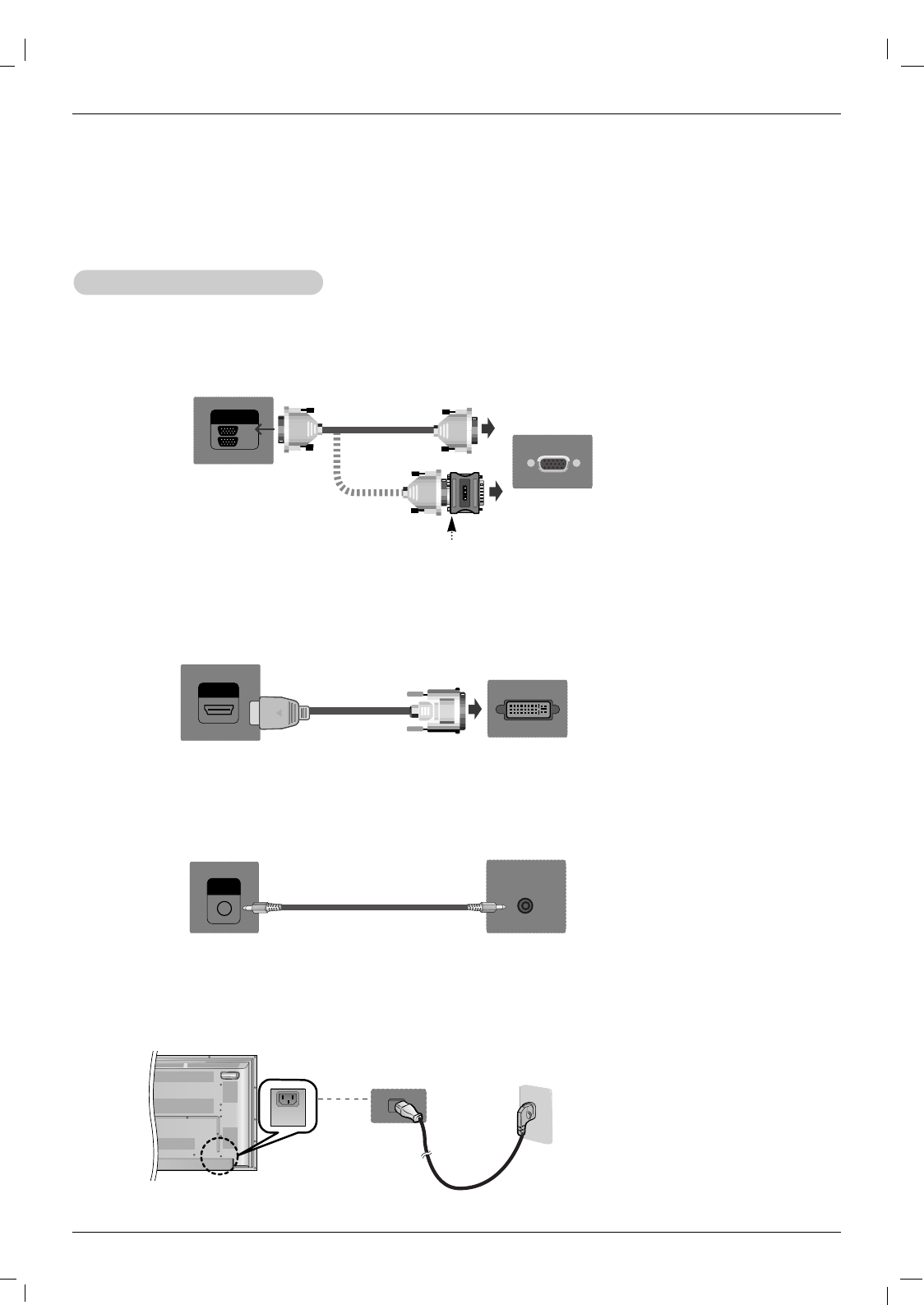
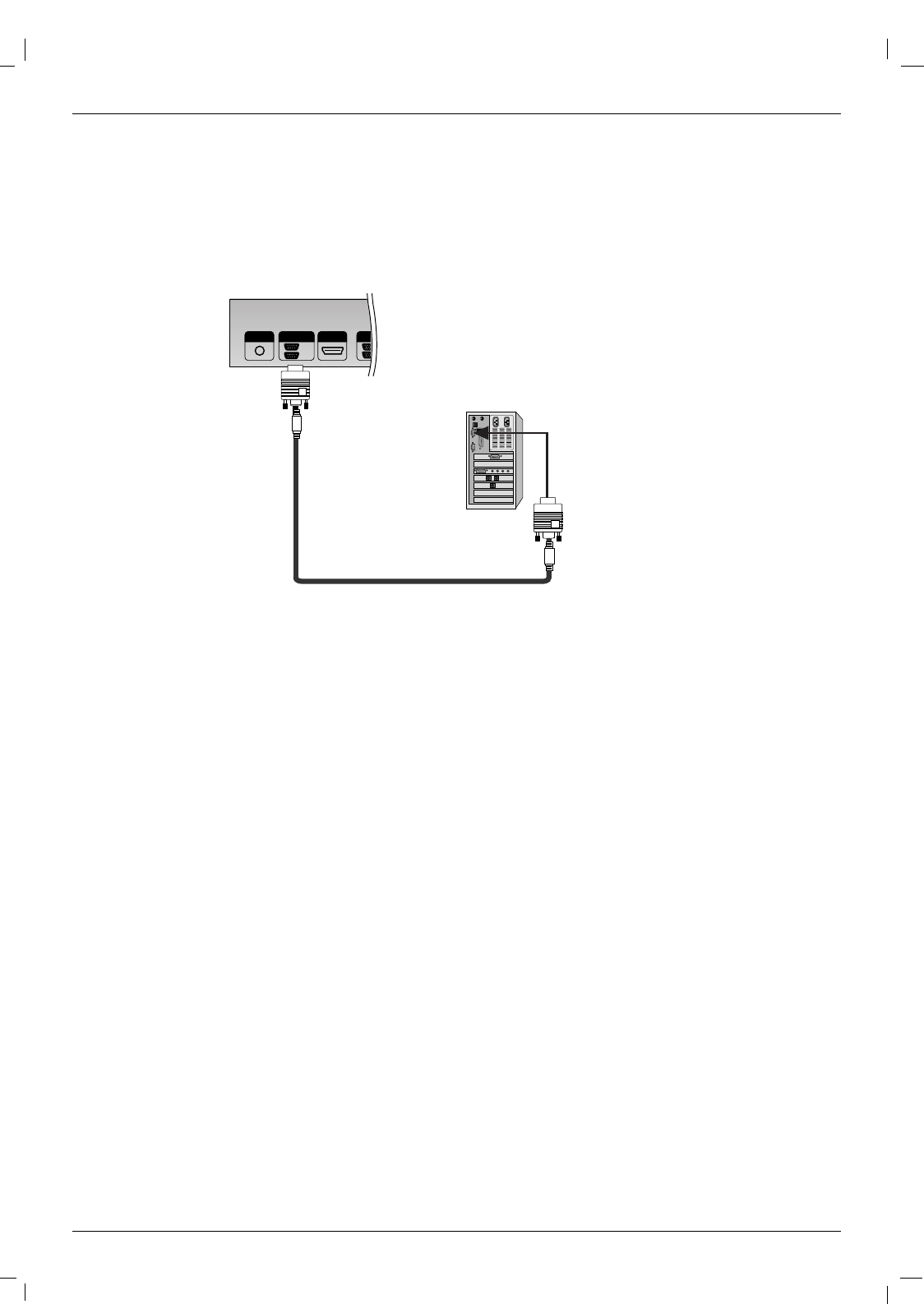
NOTE: Not all cables shown are included with the plasma display.
1. First of all, see if the computer, product and the peripherals are turned off.
Then, connect the signal input cable.
2. Connect the Audio cable.
a. When connecting with the D-Sub signal input cable.
When Connecting to your PC
When Connecting to your PC
RGB
OUT
IN
Rear side of the product.
PC
PC
MAC
b. When connecting with the HDMI to DVI signal input cable (not included).
HDMI/DVI IN
Rear side of the product.
PC
AUDIO
(RGB/DVI)
Rear side of the product.
3. Connect the power cord.
AC IN
(not included)
PC/MAC
Macintosh Adapter (not included)
Use the standard Macintosh adapter since an incompatible
adapter is available in the market. (Different signaling system)
Owner’s Manual 13
Installation
ENGLISH
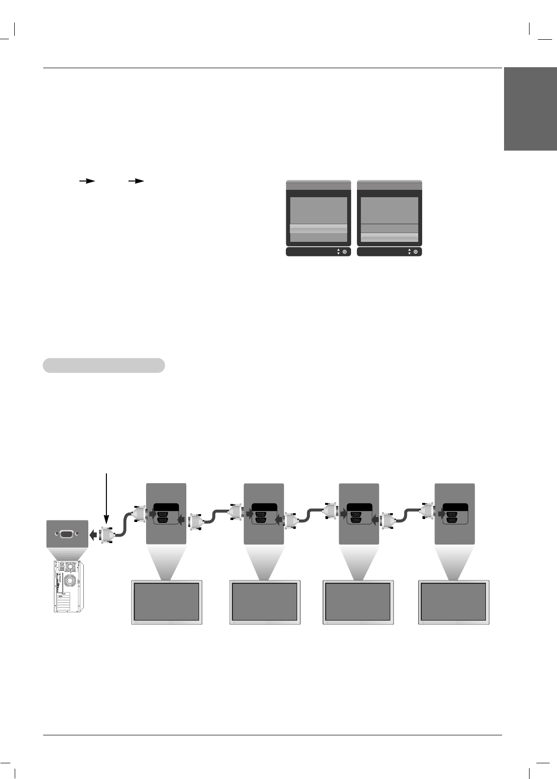
4. Turn on power by pressing the power button on the product.
Turn on the PC.
Use this function when displaying ANALOG RGB inputs of a PC to the other product.
• To use different products connected to each other Connect one end of the signal input cable(15-pin
D-Sub Signal Cable) to the RGB OUT connector of product 1 and connect the other end to the RGB IN
connector of other products.
5. Select an input signal.
Press the INPUT button on the remote control to select the input
signal.
INPUT DD/ EE SET
a. When connecting with a D-Sub signal input cable.
• Select RGB : 15-pin D-Sub analog signal.
b. When connecting with a HDMI to DVI signal input cable.
• Select HDMI/DVI : HDMI to DVI Digital signal.
Input Input
AV
Component1
Component2
RGB
HDMI/DVI
AV
Component1
Component2
RGB
HDMI/DVI
NOTES: • How to connect to two computers.
Connect the signal cables (HDMI to DVI and D-Sub) to each computer.
Press the INPUT button on the remote control to select the computer to use.
• Directly connect to a grounded power outlet on the wall or a power bar with a ground wire.
NOTES: • When multi-connecting in/out cascade format, cables to be less damaged are recommended.
We recommend that you should use cable distributor.
W
Watching RGB Outputs
atching RGB Outputs
RGB
OUT
IN
RGB
OUT
IN
RGB
OUT
IN
RGB
OUT
IN
15-pin D-Sub Signal Cable
PC
Product 1 Product 2 Product 3 Product 4
14 Plasma Monitor
Installation
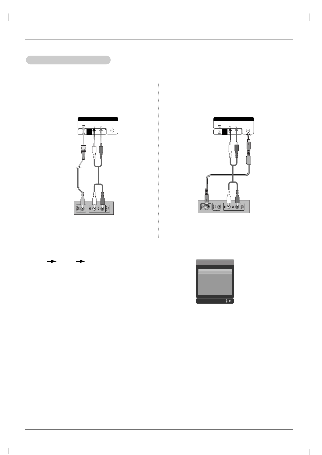
1. Connect the video cable as shown in the below figure and then connect the power cord.
2. Select an input signal.
Press the INPUT button on the remote control to select the input signal.
INPUT DD/ EE SET
a. When connecting with an BNC cable.
• Select AV.
b. When connecting with an S-Video cable.
• Select AV.
NOTES: • When the BNC cable is connected simultaneously with S-Video cable, S-Video cable is first.
When watching VCR / DVD
When watching VCR / DVD
a. When connecting with a BNC cable.
• Connect the input terminal with a proper colour match.
L-AUDIO-R S-VIDEO
AV IN
VIDEO
AV
OUT
Product
BNC Cable
(not included)
VCR/DVD Receiver
Audio Cable
(not included)
b. When connecting with a S-Video cable.
• Connect to the S-Video input terminal to watch high
image quality movies.
L-AUDIO-R S-VIDEO
AV IN
VIDEO
AV
OUT
Product
Audio Cable
(not included)
VCR/DVD Receiver
S-Video Cable
(not included)
Input
AV
Component1
Component2
RGB
HDMI/DVI
Owner’s Manual 15
Installation
ENGLISH
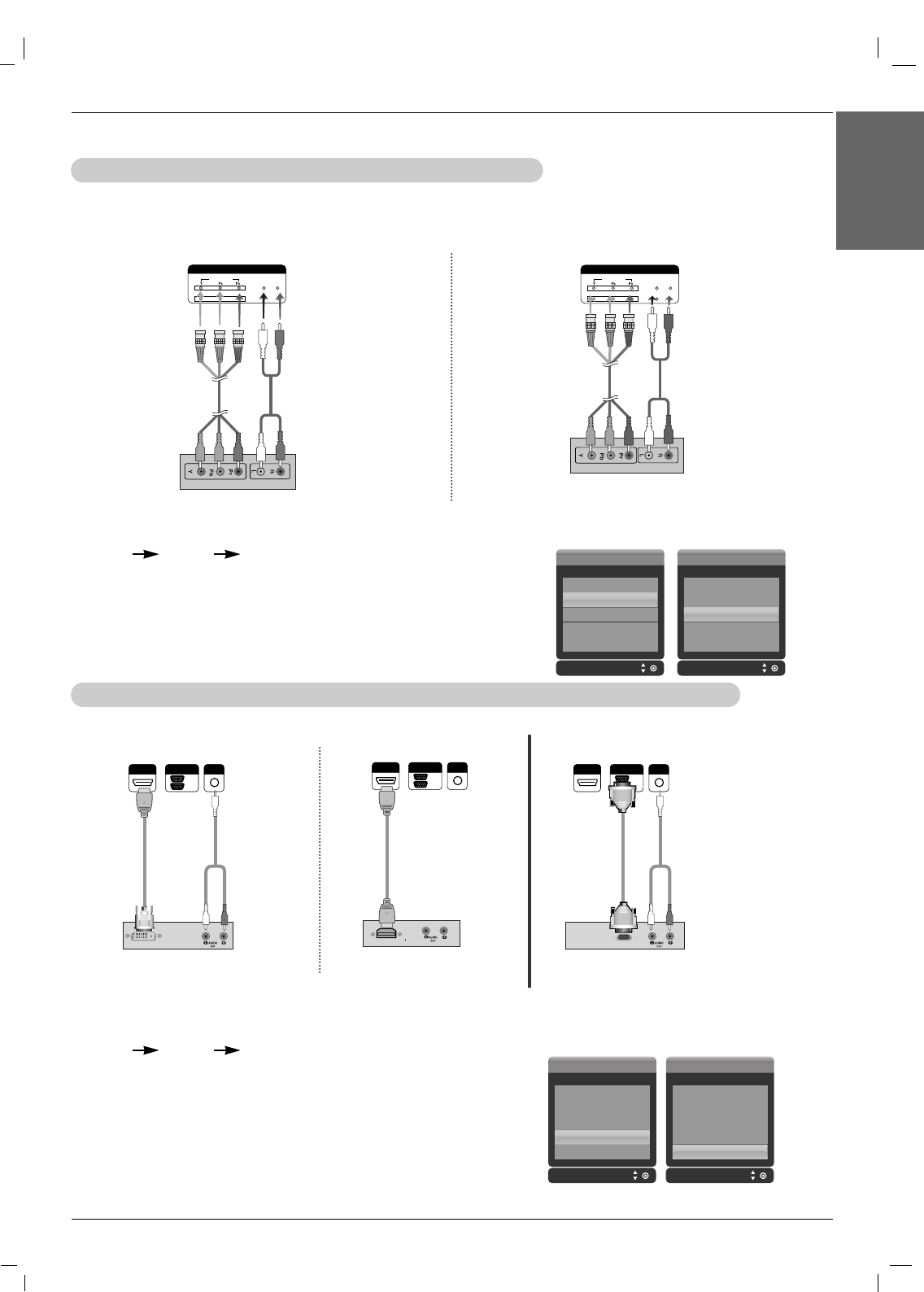
When watching HDTV/DVD(480p/576p/720p/1080i/480i/576i)
When watching HDTV/DVD(480p/576p/720p/1080i/480i/576i)
1. Connect the video/audio cable as shown in the below figure and then, connect the power cord.
• Connect the input terminal with a proper colour match.
When watching HDMI/DVI/RGB from the VCR/DVD/Set-top Box (480p/576p/720p/1080i)
When watching HDMI/DVI/RGB from the VCR/DVD/Set-top Box (480p/576p/720p/1080i)
1. Connect the video/audio cable as shown in the below figure and then connect the power cord.
COMPONENT IN
VIDEO
2
1
L-AUDIO-R
Product
Product
VCR/DVD/Set-top Box VCR/DVD/Set-top Box VCR/DVD/Set-top Box
Product Product
BNC Cable
(not included)
HDTV Receiver
Audio Cable
(not included)
COMPONENT IN
VIDEO
2
1
L-AUDIO-R
Product
BNC Cable
(not included)
HDTV Receiver
Audio Cable
(not included)
2. Select an input signal.
Press the INPUT button on the remote control to select the input signal.
INPUT DD/ EE SET
a. • Select Component 1
b. • Select Component 2
Input
AV
Component1
Component2
RGB
HDMI/DVI
Input
AV
Component1
Component2
RGB
HDMI/DVI
2. Select an input signal.
Press the INPUT button on the remote control to select the input signal.
INPUT DD/ EE SET
a. When connecting with a HDMI to DVI signal input cable.
When connecting with a HDMI signal input cable.
• Select HDMI/DVI
b. When connecting with a D-Sub signal input cable.
• Select RGB
a. b.
a. b.
AUDIO
(RGB/DVI)
HDMI/DVI IN
RGB
OUT
IN
AUDIO
(RGB/DVI)
HDMI/DVI IN
RGB
OUT
IN
AUDIO
(RGB/DVI)
HDMI/DVI IN
RGB
OUT
IN
HDMI to
DVI Signal
Cable (not
included)
HDMI Signal
Cable (not
included)
(not includ-
ed) Cable RCA-PC
Audio
Cable
RCA-PC
Audio Cable
Input Input
AV
Component1
Component2
RGB
HDMI/DVI
AV
Component1
Component2
RGB
HDMI/DVI
16 Plasma Monitor
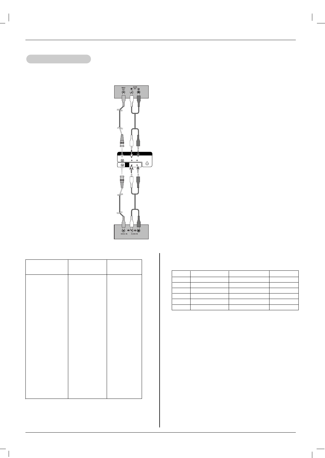
Installation
• When you set the input signal of the main screen as 'AV (CVBS)', you can transmit the signal that you're watching
to the AV output terminal.
W
Watching
atching A
AV Outputs
V Outputs
L-AUDIO-R S-VIDEO
AV IN
VIDEO
AV
OUT
Video/TV
Video/TV
BNC Cable
(not included)
BNC Cable
(not included)
Audio Cable
(not included)
Audio Cable
(not included)
Product
NOTES: • When multi-connecting in/out cascade format, cables to be less damaged are recommended.
We recommend that you should use cable distributor.
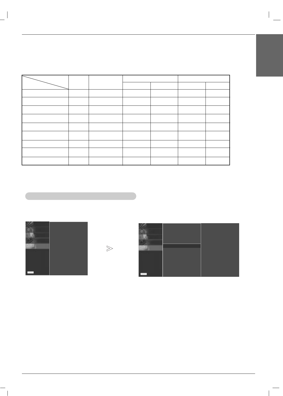
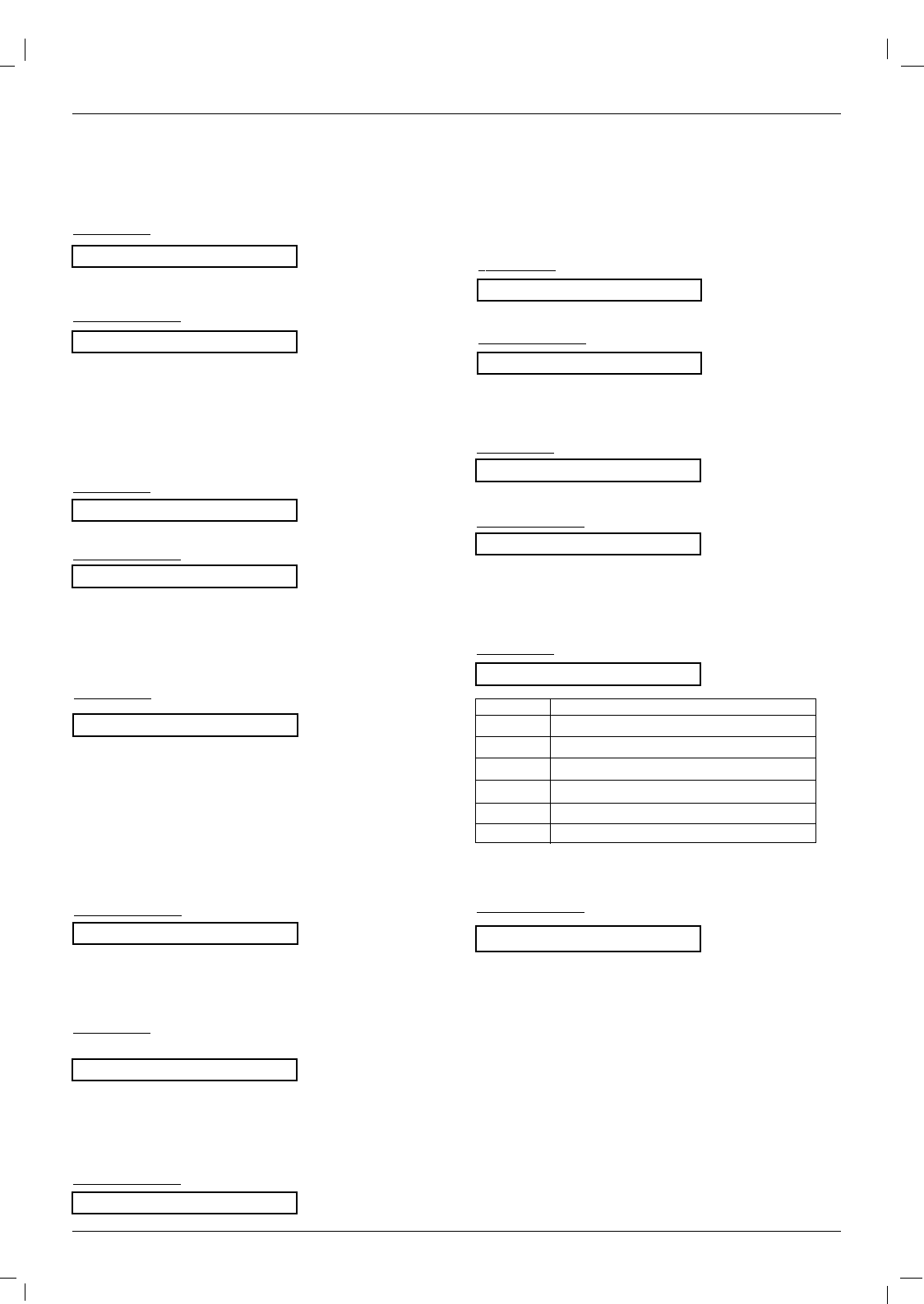
PC Mode – Preset Mode
Resolution Horizontal
Frequency(kHz)
31.468
31.469
31.469
37.500
43.269
37.879
46.875
53.674
49.725
48.363
60.023
68.677
44.772
47.693
47.700
47.700
63.981
79.980
75.000
1. VGA 640 x 350
2. VGA 720 x 400
3. VGA 640 x 480
4. VESA 640 x 480
5. VESA 640 x 480
6. VESA 800 x 600
7. VESA 800 x 600
8. VESA 800 x 600
9. MAC 832 x 624
10.VESA1024 x 768
11.VESA1024 x 768
12.VESA1024 x 768
13. VESA1280 x 720
14. VESA1280 x 768
15. VESA1360 x 768
16. VESA1366 x 768
17. VESA1280 x 1024
18. VESA 1280 x 1024
19.VESA 1600 x 1200
70.09
70.08
59.94
75.00
85.00
60.31
75.00
85.06
74.55
60.00
75.02
85.00
59.85
59.99
60.00
60.00
60.02
75.02
60.00
Vertical
Frequency(Hz)
DTV Mode
Component 1/2
O
O
O
O
O
O
RGB
X
X
O
O
O
O
HDMI
X
X
O
O
O
O
RGB : Mode 1 ~ Mode 19
HDMI/DVI : Mode 1 ~ Mode 17
Signal
480i
576i
480p
576p
720p
1080i
NOTES: We recommend using 1360*768, 60Hz (50PM4M) for
the PC mode, they provide the best picture quality. (
If the resolu-
tion of PC is over UXGA, there will be no picture on the set.)

Owner’s Manual 17
Operation
ENGLISH
Operation
Operation
Your Monitor's OSD (On Screen Display) may differ slightly from what is shown in this manual.
Menu Language Selection
Menu Language Selection
T
Turning on the Monitor
urning on the Monitor
Turning on the Monitor just after installation
1. Connect power cord correctly. At this moment, the Monitor is switched to standby mode.
2. Press the INPUT or button on the Monitor or press the POWER, INPUT button on the remote
control and then the Monitor will switch on.
-The menus can be shown on the screen in the selected language. First select your language.
1. Press the MENU button and then use DD/ EEbutton to select the SPECIAL menu.
2. Press the GGbutton and then use DD/ EEbutton to select Language.
3. Press the GGbutton and then use DD/ EEbutton to select your desired language.
From this point on, the on-screen menus will be shown in the language of your choice.
4. Press the
EXIT
button to save the new settings.
• Press the MENU button to return to the previous menu.
18 Plasma Monitor
Operation
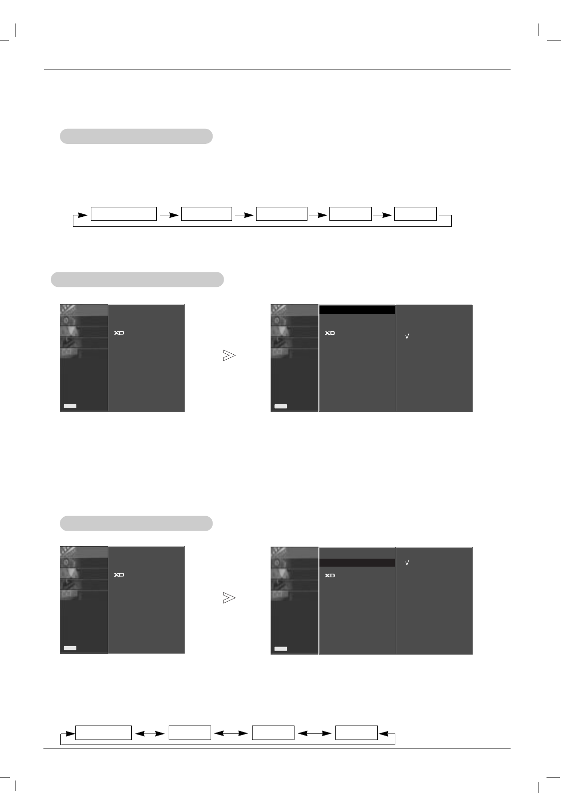
PSM (Picture Status Memory)
PSM (Picture Status Memory)
CSM (Colour Status Memory)
CSM (Colour Status Memory)
- Readjust Picture menu settings for each following input source as preferred.
Picture Menu Options
Picture Menu Options
1. Press the PSM button
- This function adjusts the set to the best picture appearance.
- When adjusting picture options (contrast, brightness, colour, sharpness and tint) manually, PSM is automatically
changed to
User
.
• Each press of the PSM button changes the screen display as shown below.
• You can also select
Dynamic
,
Standard
,
Mild
or
User1/2
in the PICTURE menu.
• Picture options
Dynamic
,
Standard
and
Mild
are preset and programmed for good picture quality at
the factory and cannot be changed.
Dynamic Standard Mild User1 User2
- To initialize values (reset to default settings), select the
Cool
option.
1. Press the MENU button and then use DD / EEbutton to select the PICTURE menu.
2. Press the GGbutton and then use DD / EEbutton to select
CSM
.
3. Press the GGbutton and then use DD / EEbutton to select the desired colour temperature.
4. Press the
EXIT
button to save the new settings.
• Each press of DD/ EEbutton changes the screen display as shown below.
Cool Normal Warm User
PICTURE 0
SOUND0
TIME0
SPECIAL0
SCREEN0
Prev.
Menu
PSM
CSM GG
Advanced
Reset
Cool
Normal
Warm
User
PICTURE0
SOUND0
TIME0
SPECIAL0
SCREEN0
Prev.
Menu
Dynamic
Standard
Mild
User1
User2
1. Press the MENU button and then use DD / EEbutton to select the PICTURE menu.
2. Press the GGbutton and then use DD / EEbutton to select
PSM
.
3. Press the GGbutton and then use DD / EEbutton to select
User1
or
User2
.
4. Press the GGbutton and then use DD / EEbutton to select the desired picture option (Contrast,Brightness,
Colour,Sharpness or Tint).
5. Press the GGbutton and then use FF / GGbutton to make appropriate adjustments.
6. Press the
EXIT
button to save the new settings.
- You can adjust picture contrast, brightness, colour, sharpness, and tint to the levels you prefer.
Manual Picture Control (user option)
Manual Picture Control (user option)
PSM GG
CSM
Advanced
Reset
SOUND0
TIME0
SPECIAL0
SCREEN0
Prev.
Menu
PSM
CSM
Advanced
Reset
PICTURE GG
SOUND0
TIME0
SPECIAL0
SCREEN0
Prev.
Menu
PSM
CSM
Advanced
Reset
PICTURE GG
Owner’s Manual 19
Operation
ENGLISH
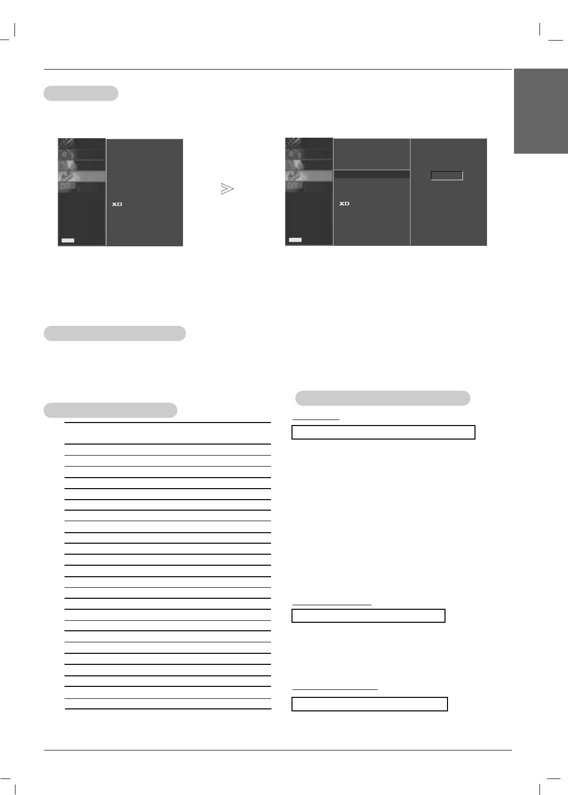
XD
XD
Manual Colour
Manual Colour T
Temperature Control (
emperature Control (CSM
CSM set to user option)
set to user option)
- You can adjust red, green, or blue to any colour temperature you prefer.
1. Press the MENU button and then use DD / EEbutton to select the PICTURE menu.
2. Press the GGbutton and then use DD / EEbutton to select CSM .
3. Press the GGbutton and then use DD / EEbutton to select User.
4. Press the GGbutton and then use DD / EEbutton to select Red, Green or Blue.
5. Use the FF / GGbutton to make appropriate adjustments.
• The adjustment range of Red, Green and Blue is -40 ~ +40.
6. Press the
EXIT
button to save the new settings.
PICTURE0
SOUND0
TIME0
SPECIAL0
SCREEN0
Prev.
Menu
PSM
CSM
Advanced
Reset
Auto
Manual
XD Contrast
XD Colour
XD NR
MPEG NR
GG
On
On
0
Off
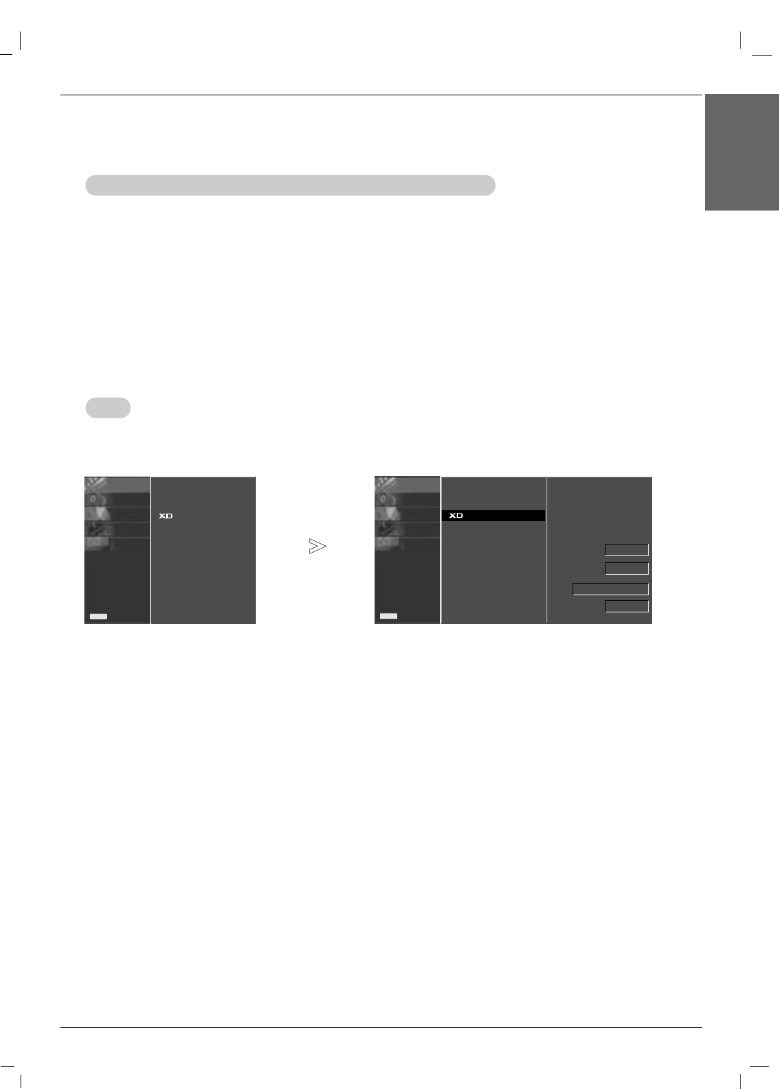
1. Press the MENU button and then use DD / EEbutton to select the PICTURE menu.
2. Press the GGbutton and then use DD / EEbutton to select
XD
.
3. Press the GGbutton and then use DD / EEbutton to select
Auto
or
Manual
.
4. Press the
EXIT
button to save the new settings.
* Selecting the Manual
This menu is activated after selecting the User1 or User2 of Picture Mode.
1. Press the GGbutton and then DD / EEbutton to select XD Contrast,XD Colour,XD NR or MPEG NR.
2. Press the GGbutton and then DD / EEbutton to select On or Off.
3. Press the
EXIT
button to save the new settings.
•XD Contrast : Optimizing the contrast automatically according to the brightness of the reflection.
•XD Colour : Adjusting the colours of the reflection automatically to reproduce as closely as possible to the natural colours.
•XD NR : Removing the noise up to the point where it does not damage the original picture.
•MPEG NR : To reduce the picture noise which may appear on the screen during watching the Monitor.
-XD is LG electronic's unique picture improving technology to display a real HD source through an
advanced digital signal processing algorithm.
- It’s not available to use this function in PC[RGB/HDMI] mode.
SOUND0
TIME0
SPECIAL0
SCREEN0
Prev.
Menu
PSM
CSM
Advanced
Reset
PICTURE GG
20 Plasma Monitor
Operation
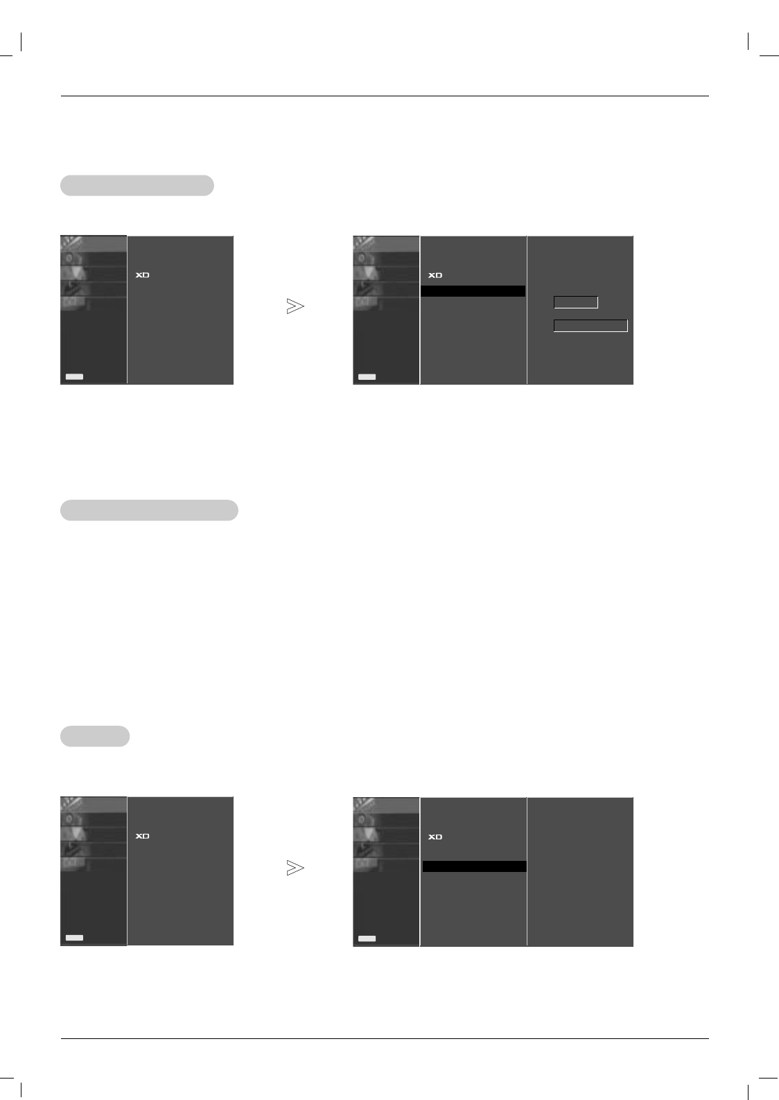
Advanced - Cinema
Advanced - Cinema
PICTURE0
SOUND0
TIME0
SPECIAL0
SCREEN0
Prev.
Menu
PSM
CSM
Advanced GG
Reset
Cinema
Black level
Off
Auto
-Set up the monitor for the best picture appearance for viewing movies.
- This feature operates only in AV, S-Video and Component 480i/576i mode.
1. Press the MENU button and then use DD / EEbutton to select the PICTURE menu.
2. Press the GGbutton and then use DD / EEbutton to select Advanced.
3. Press the GGbutton and then use DD / EEbutton to select Cinema.
4. Press the FF / GGbutton to select On or Off.
5. Press the
EXIT
button to save the new settings.
Advanced - Black level
Advanced - Black level
-When you watch the movie, this function adjusts the set to the best picture appearance. Adjusting the contrast and
the brightness of the screen using the black level of the screen.
- This function works in the following mode: AV (NTSC-M), S-Video (NTSC-M) or HDMI.
1. Press the MENU button and then use DD / EEbutton to select the PICTURE menu.
2. Press the GGbutton and then use DD / EEbutton to select Advanced.
3. Press the GGbutton and then use DD / EEbutton to select Black level.
4. Press the FF / GGbutton to select Auto, Low or High.
•Low
:
The reflection of the screen gets darker.
•High
:
The reflection of the screen gets brighter.
5. Press the
EXIT
button to save the new settings.
Picture Menu Options
Picture Menu Options
PICTURE0
SOUND0
TIME0
SPECIAL0
SCREEN0
Prev.
Menu
PSM
CSM
Advanced
Reset GGTo set
Reset
Reset
1. Press the MENU button and then DD/ EEbutton to select the PICTURE menu.
2. Press the GGbutton and then DD/ EEbutton to select Reset.
3. Press the GGbutton.
This function operates in current mode.
To initialize the adjusted value
SOUND0
TIME0
SPECIAL0
SCREEN0
Prev.
Menu
PSM
CSM
Advanced
Reset
PICTURE GG
SOUND0
TIME0
SPECIAL0
SCREEN0
Prev.
Menu
PSM
CSM
Advanced
Reset
PICTURE GG
Owner’s Manual 21
ENGLISH
Sound Menu Options
Sound Menu Options
Operation
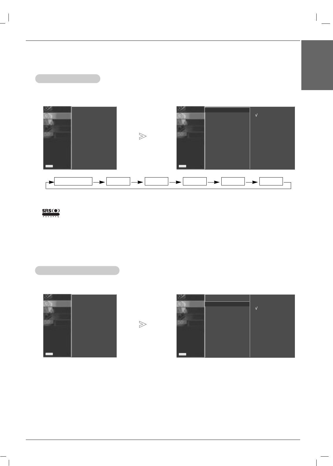
SSM
SSM
-This function lets you enjoy the best sound without any special adjustment because the set automatically selects the
appropriate sound option based on the program content.
• You can also select
Surround MAX
,
Flat
,
Music
,
Movie
,
Sports
or
User
in the SOUND menu.
•The sound
Surround MAX
,
Flat
,
Music
,
Movie
and
Sports
are programmed for good sound reproduction at the fac-
tory and cannot be changed.
Surround MAX Flat Music Movie Sports User
-is a trademark of SRS Labs, Inc.
- TruSurround XT technology is incorporated under license from SRS Labs, Inc.
R
TTruSurround XTruSurround XT
-This feature maintains an equal volume level; even if you change channels.
1. Press the MENU button and then use DD / EEbutton to select the SOUND menu.
2. Press the GGbutton and then use DD / EEbutton to select AVL.
3. Press the GGbutton and then use DD / EEbutton to select On or Off.
4. Press the
EXIT
button to save the new settings.
A
AVL
VL (Auto V
(Auto Volume Leveler)
olume Leveler)
PICTURE0
SOUND0
TIME0
SPECIAL0
SCREEN0
Prev.
Menu
On
Off
SSM
AVL GG
Balance 0
Speaker
PICTURE0
SOUND GG
TIME0
SPECIAL0
SCREEN0
Prev.
Menu
SSM
AVL
Balance 0
Speaker
PICTURE0
SOUND GG
TIME0
SPECIAL0
SCREEN0
Prev.
Menu
SSM
AVL
Balance 0
Speaker
PICTURE0
SOUND0
TIME0
SPECIAL0
SCREEN0
Prev.
Menu
Surround MAX
Flat
Music
Movie
Sports
User
SSM GG
AVL
Balance 0
Speaker
22 Plasma Monitor
Operation
1. Press the MENU button and then use DD / EEbutton to select the SOUND menu.
2. Press the GGbutton and then use DD / EEbutton to select Speaker.
3. Press the GGbutton and then use DD / EEbutton to select On or Off.
4. Press the
EXIT
button to save the new settings.
Speaker
Speaker
PICTURE0
SOUND0
TIME0
SPECIAL0
SCREEN0
Prev.
Menu
On
Off
SSM
AVL
Balance 0
Speaker GG
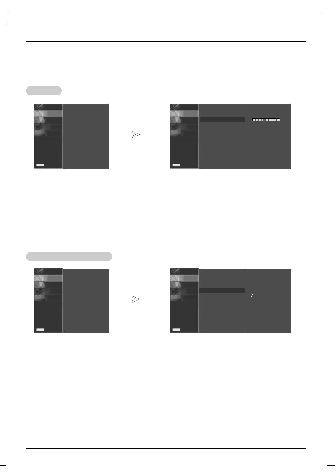
1. Press the MENU button and then use DD / EEbutton to select the SOUND menu.
2. Press the GGbutton and then use DD / EEbutton to select Balance.
3. Press the GGbutton and then use FF / GGbutton to make appropriate adjustments.
4. Press the
EXIT
button to save the new settings.
Balance
Balance
PICTURE0
SOUND0
TIME0
SPECIAL0
SCREEN0
Prev.
Menu
SSM
AVL
Balance 0GG
Speaker
L R
Sound Menu Options
Sound Menu Options
PICTURE0
SOUND GG
TIME0
SPECIAL0
SCREEN0
Prev.
Menu
SSM
AVL
Balance 0
Speaker
PICTURE0
SOUND GG
TIME0
SPECIAL0
SCREEN0
Prev.
Menu
SSM
AVL
Balance 0
Speaker
Owner’s Manual 23
ENGLISH
Operation
T
Timer Menu Options
imer Menu Options
Clock Setup
Clock Setup
PICTURE0
SOUND0
TIME GG
SPECIAL0
SCREEN0
Prev.
Menu
Clock
Off time
On time
Auto sleep
PICTURE0
SOUND0
TIME GG
SPECIAL0
SCREEN0
Prev.
Menu
Clock
Off time
On time
Auto sleep
PICTURE0
SOUND0
TIME0
SPECIAL0
SCREEN0
Prev.
Menu
Clock GG
Off time
On time
Auto sleep
- - : - -
PICTURE0
SOUND0
TIME0
SPECIAL0
SCREEN0
Prev.
Menu
Clock
Off time
On time GG
Auto sleep
- - : - -
30
-If current time setting is wrong, correct the clock setting.
1. Press the MENU button and then use DD / EEbutton to select the TIME menu.
2. Press the GGbutton and then use DD / EEbutton to select Clock.
3. Press the GGbutton and then use DD / EEbutton to set the hour.
4. Press the GGbutton and then use DD / EEbutton to set the minutes.
5. Press the
EXIT
button to save the new settings.
- Timer function operates only if current time has already been set.
- Off-Time function overrides On-Time function if they are set to the same time.
- If you do not press any button within 2 hours after the monitor turns on with the On Time function, the monitor will auto-
matically revert to standby mode.
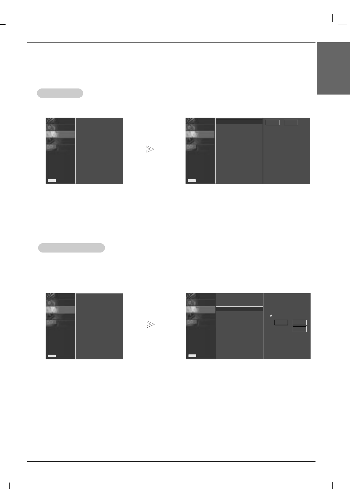
On/Of
On/Off
f T
Time Setup
ime Setup
1. Press the MENU button and then use DD / EEbutton to select the TIME menu.
2. Press the GGbutton and then use DD / EEbutton to select Off time or On time.
3. Press the GGbutton and then use DD / EEbutton to select On.
• To cancel On/Off time function, select Off.
4. Press the GGbutton and then use DD / EEbutton to set the hour.
5. Press the GGbutton and then use DD / EEbutton to set the minutes.
For only On time function; Press the GGbutton and then use DD / EEbutton to set volume level.
6. Press the
EXIT
button to save the new settings.
On
Off
Volume
24 Plasma Monitor
Operation
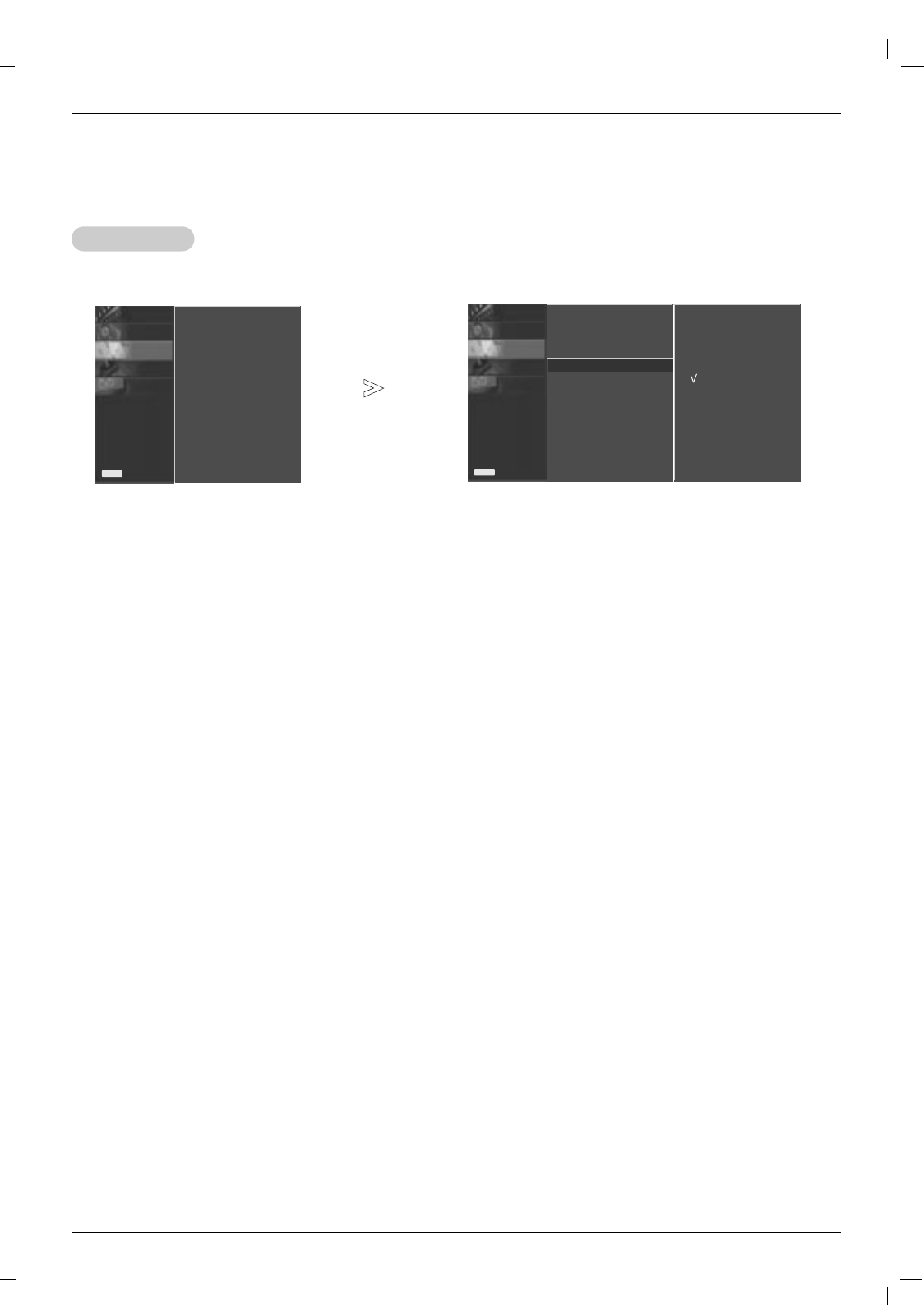
Auto sleep
Auto sleep
PICTURE0
SOUND0
TIME0
SPECIAL0
SCREEN0
Prev.
Menu
Clock
Off time
On time
Auto sleep GG
-If there is no input signal, the Monitor turns off automatically after 10 minutes.
1. Press the MENU button and then use DD / EEbutton to select the TIME menu.
2. Press the GGbutton and then use DD / EEbutton to select Auto sleep.
3. Press the GGbutton and then use DD / EEbutton to select On or Off.
4. Press the
EXIT
button to save the new settings.
On
Off
T
Timer Menu Options
imer Menu Options
PICTURE0
SOUND0
TIME GG
SPECIAL0
SCREEN0
Prev.
Menu
Clock
Off time
On time
Auto sleep
Owner’s Manual 25
ENGLISH
PICTURE0
SOUND0
TIME0
SPECIAL0
SCREEN0
Prev.
Menu
Operation
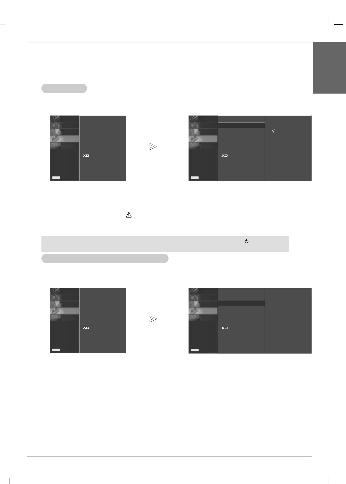
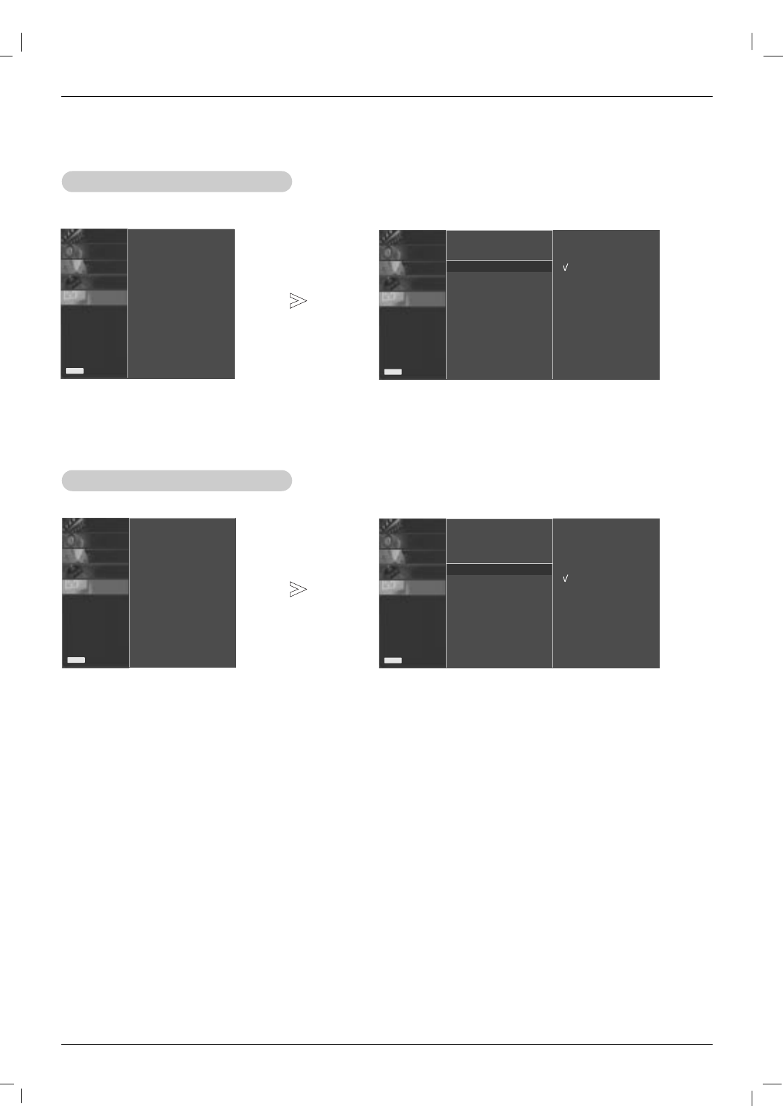
Child Lock
Child Lock
PICTURE0
SOUND0
TIME0
SPECIAL GG
SCREEN0
Prev.
Menu
Language
Child lock
ISM Method
Set ID
Tile mode
Low power
Demo
-The monitor can be set up so that it can only be used with the remote control.
- This feature can be used to prevent unauthorized viewing by disabling the front panel controls.
-This Monitor is programmed to remember which option it was last set to even if you turn the monitor off.
1. Press the MENU button and then use DD / EEbutton to select the SPECIAL menu.
2. Press the GGbutton and then use DD / EEbutton to select Child lock.
3. Press the GGbutton and then use DD / EEbutton to select On or Off.
• When you select On, the display ‘ Child lock On’appears on the screen if any button
on the front panel is pressed.
4. Press the
EXIT
button to save the new settings.
Special Menu Options
Special Menu Options
Language
Child lock GG
ISM Method
Set ID
Tile mode
Low power
Demo
On
Off
W
-In setting Child lock ‘On’, if the monitor is turned off with the remote control, press the / I, INPUT
SELECT on the monitor or POWER, INPUT on the remote control to turn the monitor on.
- A frozen still picture from a PC/video game displayed on the screen for prolonged periods will result in an ghost
image remaining; even when you change the image. Avoid allowing a fixed or still image to remain on the Monitor's
screen for a long period of time.
1. Press the MENU button and then use DD / EEbutton to select the SPECIAL menu.
2. Press the GGbutton and then use DD / EEbutton to select ISM Method.
3. Press the GGbutton and then use DD / EEbutton to select either Normal, White wash, Orbiter, Inversion or Orb.+lnv..
• Normal
If image sticking is never a problem, ISM is not necessary - set this to Normal.
• White wash
White Wash removes permanent images from the screen. Note: An excessive permanent image may be impossible to
clear completely using White Wash. To return to normal viewing, press the any button.
• Orbiter
Orbiter may help prevent ghost images. However, it is best not to allow any fixed image to remain on the screen. To
avoid a permanent image on the screen, the image will move every 2 minutes.
• Inversion
Inversion will automatically invert the plasma display panel colour every 30 minutes.
• Orb. + lnv.
This function inverts the panel color of the screen and may help prevent ghost images. The panel color is automatically
inverted every 30 minutes and the screen will move every 2 minutes.
4. Press the
EXIT
button to save the new settings.
ISM (Image Sticking Minimization) Method
ISM (Image Sticking Minimization) Method
PICTURE0
SOUND0
TIME0
SPECIAL0
SCREEN0
Prev.
Menu
Language
Child lock
ISM Method GG
Set ID
Tile mode
Low power
Demo
Normal
White wash
Orbiter
Inversion
Orb. + lnv.
PICTURE0
SOUND0
TIME0
SPECIAL GG
SCREEN0
Prev.
Menu
Language
Child lock
ISM Method
Set ID
Tile mode
Low power
Demo
26 Plasma Monitor
Operation
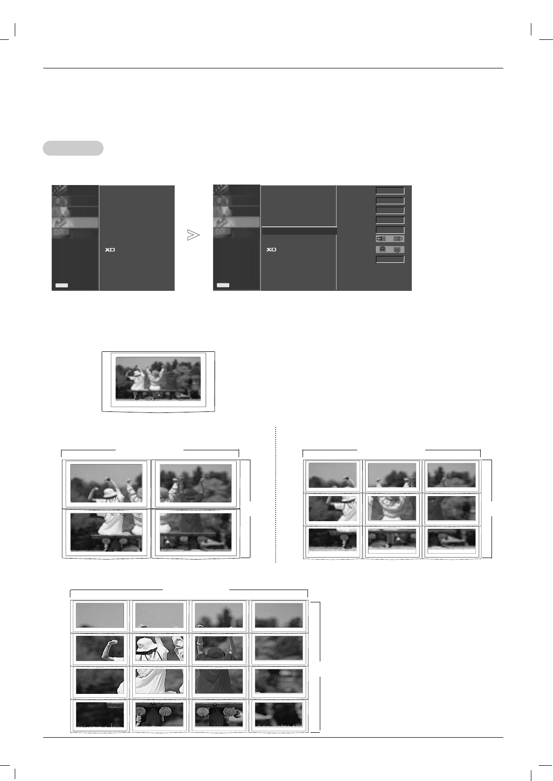
T
Tile mode
ile mode
PICTURE0
SOUND0
TIME0
SPECIAL0
SCREEN0
Prev.
Menu
Language
Child lock
ISM Method
Set ID
Tile mode GG
Low power
Demo
Tile mode
Natural
Tile ID
H-Size
V-Size
H-Position
V-Position
Reset
Off
Off
1
0
0
F G
To set
F G
It is used to
enlarge the screen
and also used with
several products
to view screen.
• Tile Mode Tile mode and choose Tile alignment and set the ID of the current product to set location.
* Only after pressing the SET button the adjustments made to the settings will be saved.
- Tile mode : row x column ( r = 1, 2, 3, 4 c = 1, 2, 3, 4)
- 4 x 4 available.
- Configuration of an integration screen is also available as well as configuration of One by one Display.
- Tile mode (product 1 ~ 4) : r(2) x c(2) - Tile mode (product 1 ~ 9) : r(3) x c(3)
row row
column
- Tile mode (product 1 ~16) : r(4) x c(4)
row
column
column
PICTURE0
SOUND0
TIME0
SPECIAL GG
SCREEN0
Prev.
Menu
Language
Child lock
ISM Method
Set ID
Tile mode
Low power
Demo
Special Menu Options
Special Menu Options
Owner’s Manual 27
Operation
ENGLISH
PICTURE0
SOUND0
TIME0
SPECIAL0
SCREEN0
Prev.
Menu
1. Press the MENU button and then use DD / EEbutton to select the SPECIAL menu.
2. Press the GGbutton and then use DD / EEbutton to select Tile mode.
3. Press the GGbutton and then DD/ EEor FF/ GG button to adjust the position.
4. Press the
EXIT
button to save the new settings.
• Natural The image is omitted by the distance between the screens to be naturally shown.
• Tile ID Select the location of the Tile by setting an ID.
• H Size Adjust the horizontal size of the screen taking into account the size of the bezel.
• V Size Adjust the vertical size of the screen taking into account the size of the bezel.
• H-Position Moving the screen position horizontally.
• V-Position Moving the screen position vertically.
• Reset Function to initialize and release Tile.
All Tile setting are released when selecting Tile recall and the screen returns to Full screen.
Language
Child lock
ISM Method
Set ID
Tile mode GG
Low power
Demo
Tile mode
Natural
Tile ID
H-Size
V-Size
H-Position
V-Position
Reset
Off
Off
1
0
0
F G
To set
F G
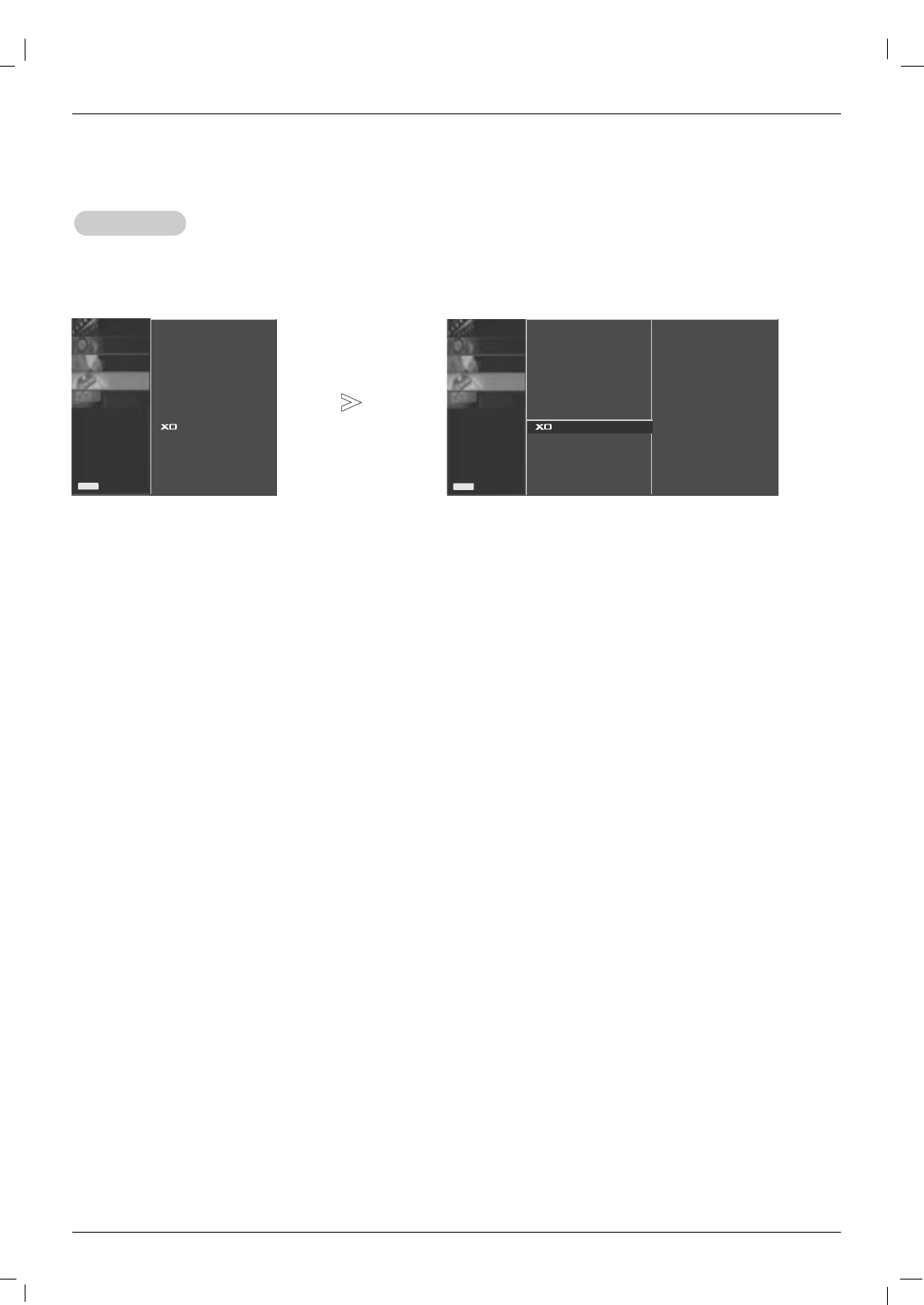
Low Power
Low Power
-Low power reduces the plasma display's power consumption.
1. Press the MENU button and then use DD / EEbutton to select the SPECIAL menu.
2. Press the GGbutton and then use DD / EEbutton to select Low power.
3. Press the GGbutton and then use DD / EEbutton to select On or Off.
• When you select On, the screen darkens.
4. Press the
EXIT
button to save the new settings.
PICTURE0
SOUND0
TIME0
SPECIAL0
SCREEN0
Prev.
Menu
Language
Child lock
ISM Method
Set ID
Tile mode
Low power GG
Demo
Off
On
- Tile mode (product 1 ~ 2) : r(2) x c(1)
row
column
PICTURE0
SOUND0
TIME0
SPECIAL GG
SCREEN0
Prev.
Menu
Language
Child lock
ISM Method
Set ID
Tile mode
Low power
Demo
PICTURE0
SOUND0
TIME0
SPECIAL GG
SCREEN0
Prev.
Menu
Language
Child lock
ISM Method
Set ID
Tile mode
Low power
Demo
28 Plasma Monitor
Operation
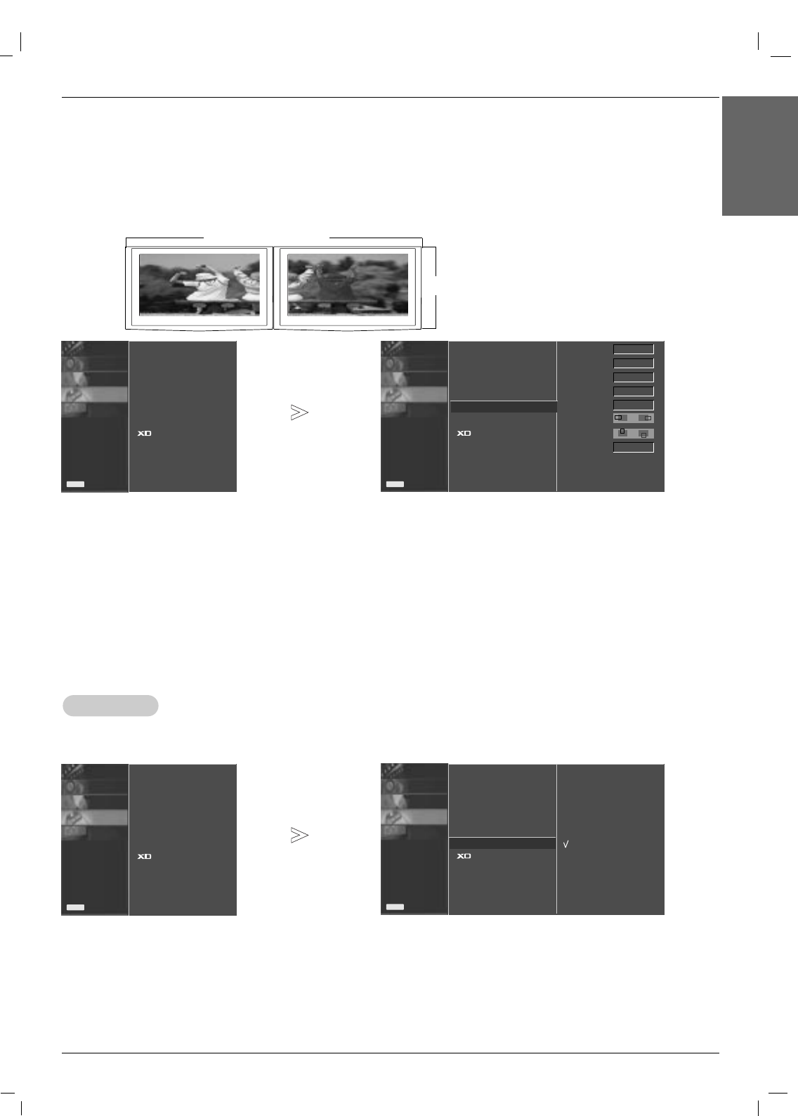
XD DEMO
XD DEMO
-Use it to see the difference between XD Demo on and XD Demo off.
- It’s not available to use this function in RGB[PC], HDMI[PC] mode.
1. Press the MENU button and then DD / EEbutton to select the SPECIAL menu.
2.
Press the GGbutton and then use DD/ EEbutton to select
XD Demo.
3. Press the GGbutton to begin XD Demo.
4. To stop XD Demo, press the MENU or EXIT button.
PICTURE0
SOUND0
TIME0
SPECIAL0
SCREEN0
Prev.
Menu
Language
Child lock
ISM Method
Set ID
Tile mode
Low power
Demo GGTo start
Special Menu Options
Special Menu Options
PICTURE0
SOUND0
TIME0
SPECIAL GG
SCREEN0
Prev.
Menu
Language
Child lock
ISM Method
Set ID
Tile mode
Low power
Demo
Owner’s Manual 29
ENGLISH
Operation
Screen Menu Options
Screen Menu Options
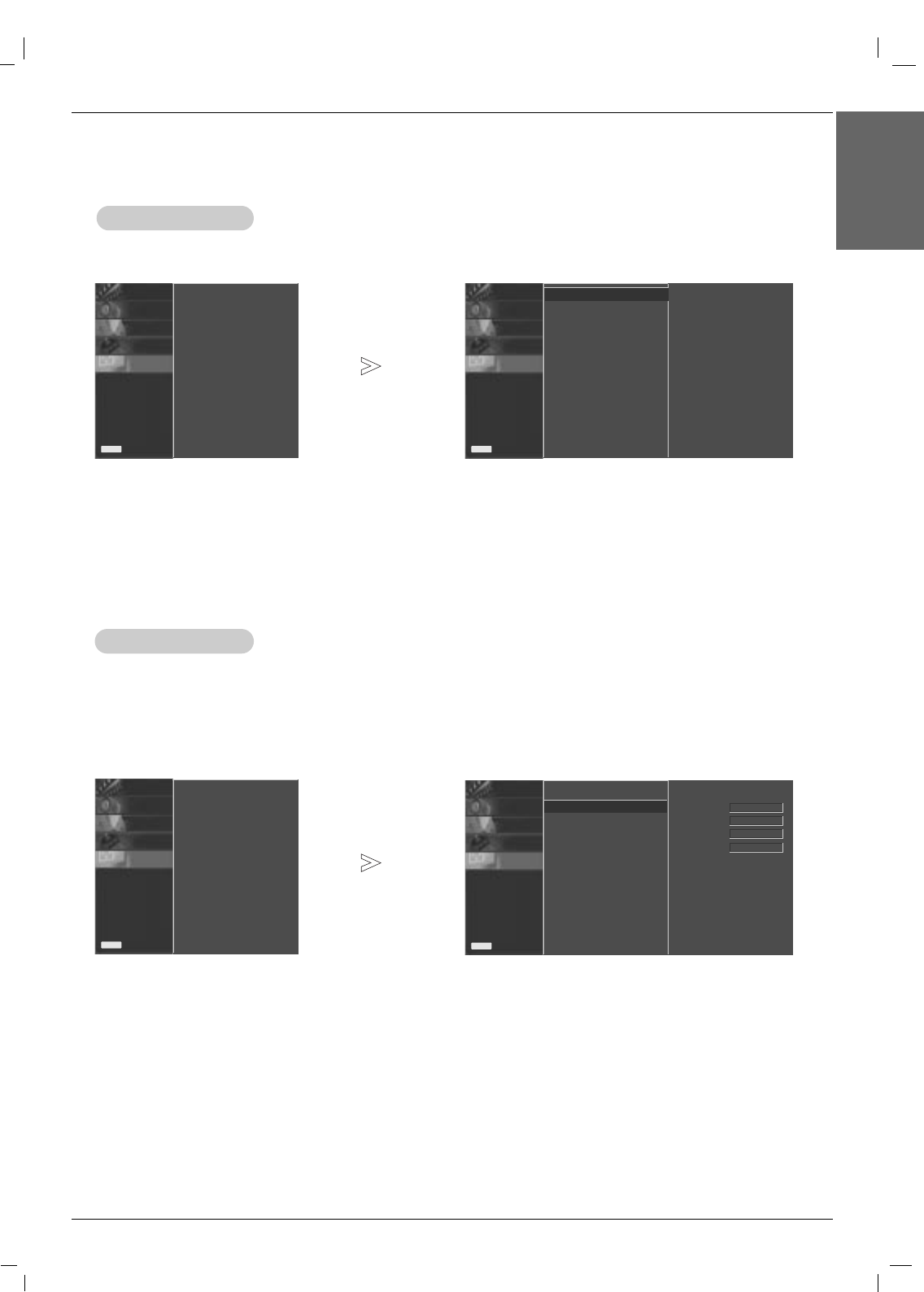
Auto Configure
Auto Configure
1. Press the MENU button and then use DD/ EEbutton to select the SCREEN menu.
2. Press the GGbutton and then use DD/ EEbutton to select Auto config..
3. Press the GGbutton to start Auto config..
• When Auto config. has finished, OK will be shown on screen.
•If the position of the image is still not correct, try Auto adjustment again.
4. If picture needs to be adjusted more after Auto adjustment in RGB (PC), you can adjust the Manual config..
5.
Press the
EXIT
button to save the new settings.
PICTURE0
SOUND0
TIME0
SPECIAL0
SCREEN GG
Prev.
Menu
Auto config.
Manual config.
XGA Mode
ARC
Reset
PICTURE0
SOUND0
TIME0
SPECIAL0
SCREEN0
Prev.
Menu
To set
Auto config. GG
Manual config.
XGA Mode
ARC
Reset
-Automatically adjusts picture position and minimizes image shaking.
-This function works in the following mode : RGB[PC].
Manual Configure
Manual Configure
-This function works in the following mode:
RGB[PC], RGB[DTV], HDMI[DTV], COMPONENT[DTV] mode only
- If the picture isn’t clear after auto adjustment and especially if characters are still trembling, adjust the picture
phase manually (RGB-PC mode only).
- To correct the screen size, adjust Clock (RGB-PC mode only).
1. Press the MENU button and then DD/ EEbutton to select the
SCREEN
menu.
2. Press the GGbutton and then DD/ EEbutton to select Manual config..
3. Press the GGbutton and then DD/ EEbutton to select Phase,Clock,H-Position or V-Position.
4. Press the FF/ GGbutton to make appropriate adjustments.
5. Press the
EXIT
button to save the new settings.
PICTURE0
SOUND0
TIME0
SPECIAL0
SCREEN0
Prev.
Menu
Phase
Clock
H-Position
V-Position
Auto config.
Manual config. GG
XGA Mode
ARC
Reset
0
0
0
0
PICTURE0
SOUND0
TIME0
SPECIAL0
SCREEN GG
Prev.
Menu
Auto config.
Manual config.
XGA Mode
ARC
Reset
30 Plasma Monitor
Operation
Selecting XGA
Selecting XGA mode
mode
- To see a normal picture, match the resolution of RGB mode and selection of XGA mode.
- This function works in the following mode : RGB[PC]
1. Press the MENU button and then use DD /EEbutton to select the
SCREEN
menu.
2. Press the GGbutton and then use DD /EEbutton to select XGA Mode.
3. Press the GGbutton and then use DD /EEbutton to select the desired XGA resolution.
4. Press the
SET
button.
5. Press the
EXIT
button to save the new settings.
PICTURE0
SOUND0
TIME0
SPECIAL0
SCREEN0
Prev.
Menu
1024x768
1280x768
1360x768
1366x768
Auto config.
Manual config.
XGA Mode GG
ARC
Reset
Setting the Picture Format
Setting the Picture Format
- You can watch the screen in various picture formats; Spectacle,Full,Original,4:3, 16:9,1:1, 14:9,Zoom1,Zoom2.
1. Press the MENU button and then use DD/ EEbutton to select the
SCREEN
menu.
2. Press the GGbutton and then use DD/ EEbutton to select ARC.
3. Press the GGbutton and then use DD / EEbutton to select Spectacle,Full,Original,4:3, 16:9,1:1, 14:9 or Zoom 1/2.
• Spectacle
When your AV receives the wide screen signal, it will lead you to adjust the picture horizontally, in a nonlinear propor-
tion, to fill the entire screen.
• Full
When your AV receives the wide screen signal, it will lead you to adjust the picture horizontally or vertically, in a linear
proportion, to fill the entire screen fully. (Europe an version only)
• Original
When your AV receives the wide screen signal, it will be automatically changed to picture format to be sent.
• 4:3
This pIcture format is 4:3 of general AV.
• 16:9
You can enjoy movies (the picture format of 16:9) or general TV programmes thorough 16:9 mode. Programmes with
16:9 format are viewed naturally but 4:3 programmes are magnified on the left and right so that the screen is16:9 format.
• 1:1
This pIcture format is 1:1 of general AV. (only RGB PC, HDMI/DVI PC)
• 14:9
You can enjoy the picture format of 14:9 or general AV programmes through 14:9 mode.
Programmes with 14:9 are viewed naturally, but 4:3 programmes are magnified on the top/bottom and left/right sides.
• Zoom1, 2
You can enjoy movies on a vast screen through Zoom mode. The 4:3 programmes are magnified on the top/bottom
and left/right sides so that screen is 16:9 format. The bottom and top of the picture may be lost.
4. Press the
EXIT
button to save the new settings.
PICTURE0
SOUND0
TIME0
SPECIAL0
SCREEN0
Prev.
Menu
Spectacle
Full
Original
4:3
16:9
1:1
14:9
Zoom1
Zoom2
Auto config.
Manual config.
XGA Mode
ARC GG
Reset
Screen Menu Options
Screen Menu Options
PICTURE0
SOUND0
TIME0
SPECIAL0
SCREEN GG
Prev.
Menu
Auto config.
Manual config.
XGA Mode
ARC
Reset
PICTURE0
SOUND0
TIME0
SPECIAL0
SCREEN GG
Prev.
Menu
Auto config.
Manual config.
XGA Mode
ARC
Reset
Owner’s Manual 31
ENGLISH
Initializing (Reset to original factory settings)
Initializing (Reset to original factory settings)
-This function operates in current mode.
- To initialize the adjusted value
1. Press the MENU button and then DD/ EEbutton to select the
SCREEN
menu.
2. Press the GGbutton and then DD/ EEbutton to select Reset.
3. Press the GGbutton.
• You can initialize Phase, Clock, H-Position, V-Position (
Except ARC)
.
PICTURE0
SOUND0
TIME0
SPECIAL0
SCREEN0
Prev.
Menu
To set
Auto config.
Manual config.
XGA Mode
ARC
Reset GG
Operation
Spectacle
Full
Original
4:3
16:9
14:9
Zoom1
Zoom2
1:1
MODE
ARC AV component HDMI/DVI
DTV PC
RGB
DTV PC
O
O
O
O
O
O
O
O
X
X
X
X
O
O
X
O
O
X
X
X
X
O
O
X
O
O
X
X
X
X
X
O
X
X
X
O
X
X
X
O
O
X
O
O
X
X
X
X
X
O
X
X
X
O
PICTURE0
SOUND0
TIME0
SPECIAL0
SCREEN GG
Prev.
Menu
Auto config.
Manual config.
XGA Mode
ARC
Reset
32 Plasma Monitor
External Control Device Setup
- Connect the RS-232C input jack to an external control device (such as a computer or an A/V control system)
and control the Monitor’s functions externally.
- Connect the serial port of the control device to the RS-232C jack on the Monitor back panel.
- RS-232C connection cables are not supplied with the Monitor.
External Control Device Setup
External Control Device Setup
REMOTE
CONTROL IN AUDIO
(RGB/DVI)
HDMI/DVI IN
RL
RS-232C
(CONTROL&SERVICE)
OUT
IN
RGB
OUT
IN
COMPONENT IN
VIDEO
2
1
L-AUDIO-R L-AUDIO-R
S-VIDEO
AV IN
VIDEO
AV
OUT
EXTERNAL SPEAKER
Owner’s Manual 33
ENGLISH
External Control Device Setup
Transmission
* [Command 1]: k, j, m,d
* [Command 2]: To control Plasma Monitor set.
* [Set ID]: You can adjust the set ID to choose desired moni-
tor ID number in Special menu. Adjustment range
is 1 ~ 99. When selecting Set ID ‘0’, every con-
nected Plasma Monitor set is controlled. Set ID is
indicated as decimal (1~99) on menu and as
Hexa decimal (0x0~0x63) on transmission/receiv-
ing protocol.
* [DATA]: To transmit command data.
Transmit ‘FF’ data to read status of command.
* [Cr]: Carriage Return
ASCII code ‘0x0D’
* [ ]: ASCII code ‘space (0x20)’
[Command1][Command2][ ][Set ID][ ][Data][Cr]
OK Acknowledgement
* The Monitor transmits ACK (acknowledgement) based on
this format when receiving normal data. At this time, if the
data is data read mode, it indicates present status data. If
the data is data write mode, it returns the data of the PC
computer.
[Command2][ ][Set ID][ ][OK][Data][x]
Error Acknowledgement
* * If there is error, it returns NG
[Command2][ ][Set ID][ ][NG][Data][x]
T
Transmission / Receiving Protocol
ransmission / Receiving Protocol
• Baud rate : 9600 bps (UART)
• Data length : 8 bits
• Parity : None
• Stop bit : 1 bit
• Communication code : ASCII code
• Use a straight cable.
Communication Parameters
Communication Parameters
01. Power k a 0 ~ 1
02. Input Select k b 2 ~ 9
03. Aspect Ratio k c 1 ~ 9
04. Screen Mute k d 0 ~ 1
05. Volume Mute k e 0 ~ 1
06. Volume Control k f 0 ~ 64
07. Contrast k g 0 ~ 64
08. Brightness k h 0 ~ 64
09. Colour k i 0 ~ 64
10. Tint k j 0 ~ 64
11. Sharpness k k 0 ~ 64
12. OSD Select k l 0 ~ 1
13. Remote Lock /Key Lock k m 0 ~ 1
14. Balance k t 0 ~ 64
15. Colour Temperature k u 0 ~ 3
16. Abnormal state k z FF
17. ISM mode j p 0 ~ 8
18. Auto Configure j u 1
19. Key m c Key Code
20. Tile Mode d d 0 ~ 44
21. Tile H Size d g 0 ~ 64
22. Tile V Size d h 0 ~ 64
23. Tile ID Set d i 0 ~ 10
24. Natural Mode (In Tile mode) d j 0 ~ 1
COMMAND 1 COMMAND 2 DATA
(Hexadecimal)
Command Reference List
Command Reference List
PICTURE0
SOUND0
TIME0
SPECIAL0
SCREEN0
Prev.
Menu
Set ID
Set ID
-Use this function to specify a monitor ID number.
- Refer to ‘Real Data Mapping 1’. See page 35.
1. Press the MENU button and then use the DD /EEbutton to select the SPECIAL menu.
2. Press the GGbutton and then use DD /EEbutton to select Set ID.
3. Press the GGbutton and then use F / Gbutton to adjust Set ID to choose the desired monitor ID number.
• The adjustment range of Set ID is 1 ~ 99.
Language
Child lock
ISM Method
Set ID GG
Tile mode
Low power
Demo
1
PICTURE0
SOUND0
TIME0
SPECIAL GG
SCREEN0
Prev.
Menu
Language
Child lock
ISM Method
Set ID
Tile mode
Low power
Demo
34 Plasma Monitor
External Control Device Setup
02. Input Select (Command 2:b) (Main Picture Input)
GTo select input source for the Monitor.
You can also select an input source using the INPUT
button on the Monitor's remote control.
Transmission
Data 2 : AV
4 : Component1
5 : Component2
6 : RGB (DTV)
7 : RGB (PC)
8 : HDMI/DVI(DTV)
9 : HDMI/DVI(PC)
[k][b][ ][Set ID][ ][Data][Cr]
Acknowledgement
[b][ ][Set ID][ ][OK][Data][x]
01. Power (Command 2:a)
GTo control Power On/Off of the Monitor.
Transmission
Data 0 : Power Off 1 : Power On
[k][a][ ][Set ID][ ][Data][Cr]
Acknowledgement
[a][ ][Set ID][ ][OK][Data][x]
GTo show Power On/Off.
Transmission
[k][a][ ][Set ID][ ][FF][Cr]
Acknowledgement
Data 0 : Power Off 1 : Power On
* In a like manner, if other functions transmit ‘FF’ data
based on this format, Acknowledgement data feedback
presents status about each function.
[a][ ][Set ID][ ][OK][Data][x]
03. Aspect Ratio (Command 2:c) (Main picture format)
GTo adjust the screen format.
You can also adjust the screen format using the ARC
(Aspect Ratio Control) button on remote control or in the
Screen menu.
Transmission
Data 1 : Normal screen (4:3)
2 : Wide screen (16:9)
3 : Horizon (Spectacle)
4 : Zoom1
5 : Zoom2
6 : Original
7 : 14 : 9
8 : Full (Europe version only)
9 : 1 : 1 (PC)
[k][c][ ][Set ID][ ][Data][Cr]
Acknowledgement
[c][ ][Set ID][ ][OK][Data][x]
05. Volume Mute (Command 2:e)
GTo control volume mute on/off.
You can also adjust mute using the MUTE button on
remote control.
Transmission
Data 0 : Volume mute on (Volume off)
1 : Volume mute off (Volume on)
[k][e][ ][Set ID][ ][Data][Cr]
Acknowledgement
[e][ ][Set ID][ ][OK][Data][x]
04. Screen Mute (Command 2:d)
GTo select screen mute on/off.
Transmission
Data 0 : Screen mute off (Picture on)
1 : Screen mute on (Picture off)
Data 0 : Screen mute off (Picture on)
1 : Screen mute on (Picture off)
[k][d][ ][Set ID][ ][Data][Cr]
Acknowledgement
[d][ ][Set ID][ ][OK][Data][x]
06. Volume Control (Command 2:f)
GTo adjust volume.
You can also adjust volume with the volume buttons
on remote control.
Transmission
Data Min : 0 ~ Max : 64
•Refer to ‘Real data mapping1’. See page 35.
[k][f][ ][Set ID][ ][Data][Cr]
Acknowledgement
[f][ ][Set ID][ ][OK][Data][x]
Data 2 : AV
4 : Component1
5 : Component2
6 : RGB (DTV)
7 : RGB (PC)
8 : HDMI/DVI(DTV)
9 : HDMI/DVI(PC)
Data 0 : Volume mute on (Volume off)
1 : Volume mute off (Volume on)
Data Min : 0 ~ Max : 64
* Real data mapping 1
0 : Step 0
A : Step 10 (SET ID 10)
F : Step 15 (SET ID 15)
10 : Step 16 (SET ID 16)
63 : Step 99 (SET ID 99)
64 : Step 100
Owner’s Manual 35
ENGLISH
External Control Device Setup
13. Remote Lock /Key Lock (Command2:m)
GTo control Remote Lock on/off to the set.
This function, when controlling RS-232C, locks the remote
control and the local keys.
Transmission
[k][m][ ][Set ID][ ][Data][Cr]
Acknowledgement
Data 0: off 1: on
[m][ ][Set ID][ ][OK][Data][x]
GTo adjust the screen sharpness.
You can also adjust sharpness in the Picture menu.
Transmission
11. Sharpness (Command2:k)
Data Min: 0 ~ Max: 64
•Refer to ‘Real data mapping 1’.
[k][k][ ][Set ID][ ][Data][Cr]
Acknowledgement
[k][ ][Set ID][ ][OK][Data][x]
12. OSD Select (Command2:l)
GTo select OSD (On Screen Display) on/off.
Transmission
[k][l][ ][Set ID][ ][Data][Cr]
Acknowledgement
Data 0: OSD off 1: OSD on
[l][ ][Set ID][ ][OK][Data][x]
09. Colour (Command2:i)
GTo adjust the screen colour.
You can also adjust colour in the Picture menu.
Transmission
Data Min : 0 ~ Max : 64
•Refer to ‘Real data mapping 1’.
[k][i][ ][Set ID][ ][Data][Cr]
Acknowledgement
[i][ ][Set ID][ ][OK][Data][x]
10. Tint (Command2:j) (Video only)
GTo adjust the screen tint.
You can also adjust tint in the Picture menu.
Transmission
Data Red : 0 ~ Green : 64
•Refer to ‘Real data mapping 1’.
[k][j][ ][Set ID][ ][Data][Cr]
Acknowledgement
[j][ ][Set ID][ ][OK][Data][x]
08. Brightness (Command2:h)
GTo adjust screen brightness.
You can also adjust brightness in the Picture menu.
Transmission
Data Min : 0 ~ Max : 64
•Refer to ‘Real data mapping 1’.
[k][h][ ][Set ID][ ][Data][Cr]
Acknowledgement
[h][ ][Set ID][ ][OK][Data][x]
Data Min : 0 ~ Max : 64
Data Min : 0 ~ Max : 64
Data Red : 0 ~ Green : 64
Data Min : 0 ~ Max : 64
Data 0: OSD off 1: OSD on
Data 0: off 1: on
07. Contrast (Command 2:g)
GTo adjust screen contrast.
You can also adjust contrast in the picture menu.
Transmission
Data Min : 0 ~ Max : 64
•Refer to ‘Real data mapping1’ as shown below.
[k][g][ ][Set ID][ ][Data][Cr]
Acknowledgement
[g][ ][Set ID][ ][OK][Data][x]
Data Min : 0 ~ Max : 64
36 Plasma Monitor
External Control Device Setup
16. Abnormal state (Command2 : z)
GAbnormal State : Used to Read the power off status
when Stand-by mode.
Transmission
Data FF : Read
0 : Normal (Power on and signal exist)
1: No signal (Power on)
2 : Turn the monitor off by remote control
3 : Turn the monitor off by sleep time function
4 : Turn the monitor off by RS-232C function
6 : AC down
8 : Turn the monitor off by off time function
9 : Turn the monitor off by auto off function
[k][z][ ][Set ID][ ][Data][Cr]
Acknowledgement
[z][ ][Set ID][ ][OK][Data][x]
17. ISM mode(Command: j p)
GUsed to select the afterimage preventing function.
Transmission
Data 1 : Inversion
2 : Orbiter
3 : Orb.+Inv.
4 : White Wash
8 : Normal
[j][p][ ][Set ID][ ][Data][Cr]
Acknowledgement
[p][ ][Set ID][ ][OK][Data][x]
14. Balance (Command2:t)
GTo adjust balance.
Transmission
Data Min: 0 ~ Max: 64
•Refer to ‘Real data mapping 1’. See page 35.
[k][t][ ][Set ID][ ][Data][Cr]
Acknowledgement
[t][ ][Set ID][ ][OK][Data][x]
Data Min: 0 ~ Max: 64
* Balance : L50 ~ R50
15. Colour Temperature (Command2:u)
GTo adjust colour temperature.
You can also adjust ACC in the Picture menu.
Transmission
Data 0: Normal 1: Cool 2: Warm 3: User
[k][u][ ][Set ID][ ][Data][Cr]
Acknowledgement
[u][ ][Set ID][ ][OK][Data][x]
Data 0: Normal 1: Cool 2: Warm 3: User 20. Tile Mode(Command : d d)
GChange a Tile Mode.
Transmission
[d][d][ ][Set ID][ ][Data][x]
* The data can not be set to 0X or X0 except 00.
Acknowledgement
[d][ ][Set ID][ ][OK][Data][x]
18. Auto Configure (Command: j u)
GTo adjust picture position and minimize image shaking
automatically. Auto Configure only works in RGB-PC
mode.
Transmission
Data 1: To set
[j][u][ ][Set ID][ ][Data][Cr]
Acknowledgement
[u][ ][Set ID][ ][OK][Data][x]
19. Key (Command: m c)
GTo adjust Key code for IR remote control.
Transmission
Data Key code : Refer to See page 39.
[m][c][ ][Set ID][ ][Data][Cr]
Acknowledgement
[c][ ][Set ID][ ][OK][Data][x]
Data
00
12
13
14
...
44
Description
Tile mode is off.
1 x 2 mode(column x row)
1 x 3 mode
1 x 4 mode
...
4 x 4 mode
Owner’s Manual 37
ENGLISH
External Control Device Setup
21. Tile H Size(Command : d g)
G To set the Horizontal size.
Transmission
[d][g][ ][Set ID][ ][Data][x]
Acknowledgement
[g][ ][Set ID][ ][OK][Data][x]
22. Tile V Size(Command : d h)
GTo set the Vertical size.
Transmission
[d][h][ ][Set ID][ ][Data][x]
Acknowledgement
[h][ ][Set ID][ ][OK][Data][x]
Data Min: 0 ~ Max: 64
•Refer to ‘Real data mapping 1’. See page 35.
23. Tile ID Set (Command : d i)
GTo assign the Tile ID for Tiling function .
Transmission
[d][i][ ][Set ID][ ][Data][x]
Acknowledgement
[i][ ][Set ID][ ][OK][Data][x]
Data Min: 0 ~ Max: 10
•Refer to ‘Real data mapping 1’. See page 35.
Data Min: 0 ~ Max: 64
•Refer to ‘Real data mapping 1’. See page 35.
24. Natural Mode (In Tile mode) (Command : d j)
GThe image is omitted by the distance between the
screens to be naturally shown.
Transmission
[d][j][ ][Set ID][ ][Data][x]
Acknowledgement
[j][ ][Set ID][ ][OK][Data][x]
Data 0 : Natural Off
1 : Natural On
ff : Read Status
38 Plasma Monitor
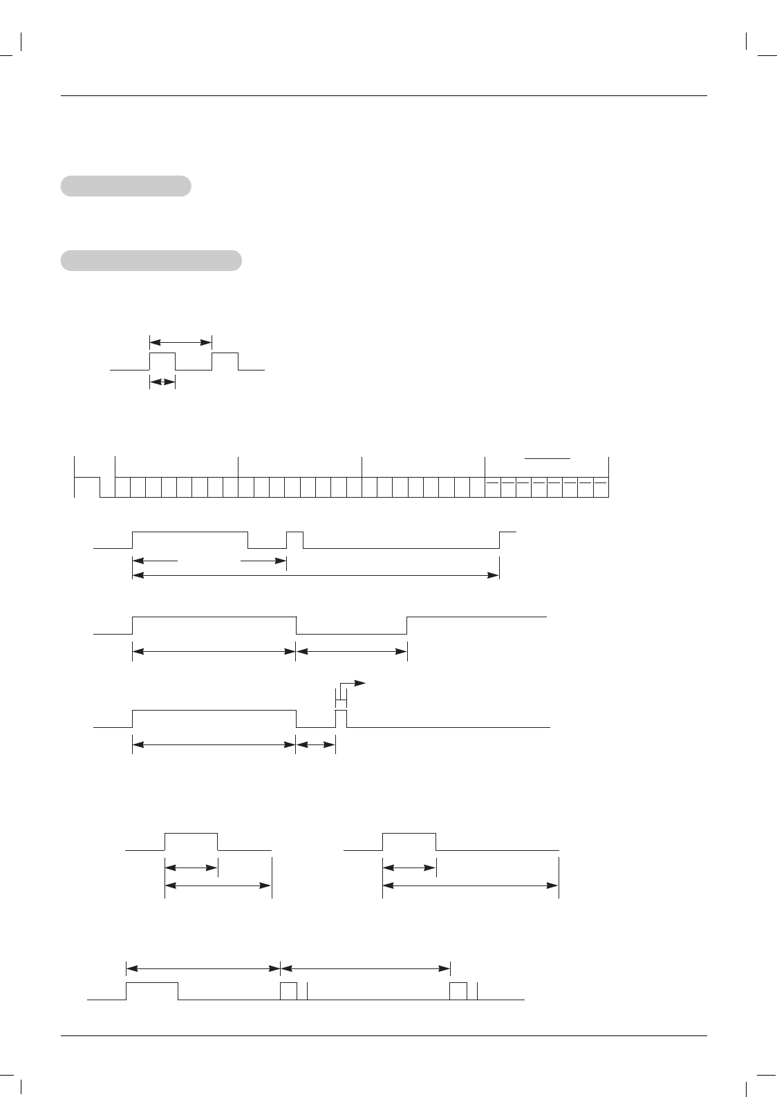
IR Code
G Connect your wired remote control to the Remote Control port on the Monitor.
G Output waveform
Single pulse, modulated with 37.917KHz signal at 455KHz
G Configuration of frame
G Repeat code
G Lead code
• 1st frame
Low
custom code
Lead
code High
custom code Data code Data code
TC
Tf
T1
C0
Carrier frequency
FCAR = 1/TC= fOSC/12
Duty ratio = T1/TC= 1/3
• Repeat frame
C1 C2 C3 C4 C5 C6 C7 C0 C1 C2 C3 C4 C5 C6 C7 D0 D1 D2 D3 D4 D5 D6 D7 D0 D1 D2 D3 D4 D5 D6 D7
Repeat code
9 ms 4.5 ms
0.55 ms
9 ms
2.25 ms
G Bit description
G Frame interval : Tf
The waveform is transmitted as long as a key is depressed.
• Bit “0”
Tf Tf
Tf=108ms @455KHz
0.56 ms 0.56 ms
1.12 ms
• Bit “1”
2.24 ms
How to Connect
How to Connect
Remote Control IR Code
Remote Control IR Code
IR Code
IR Code
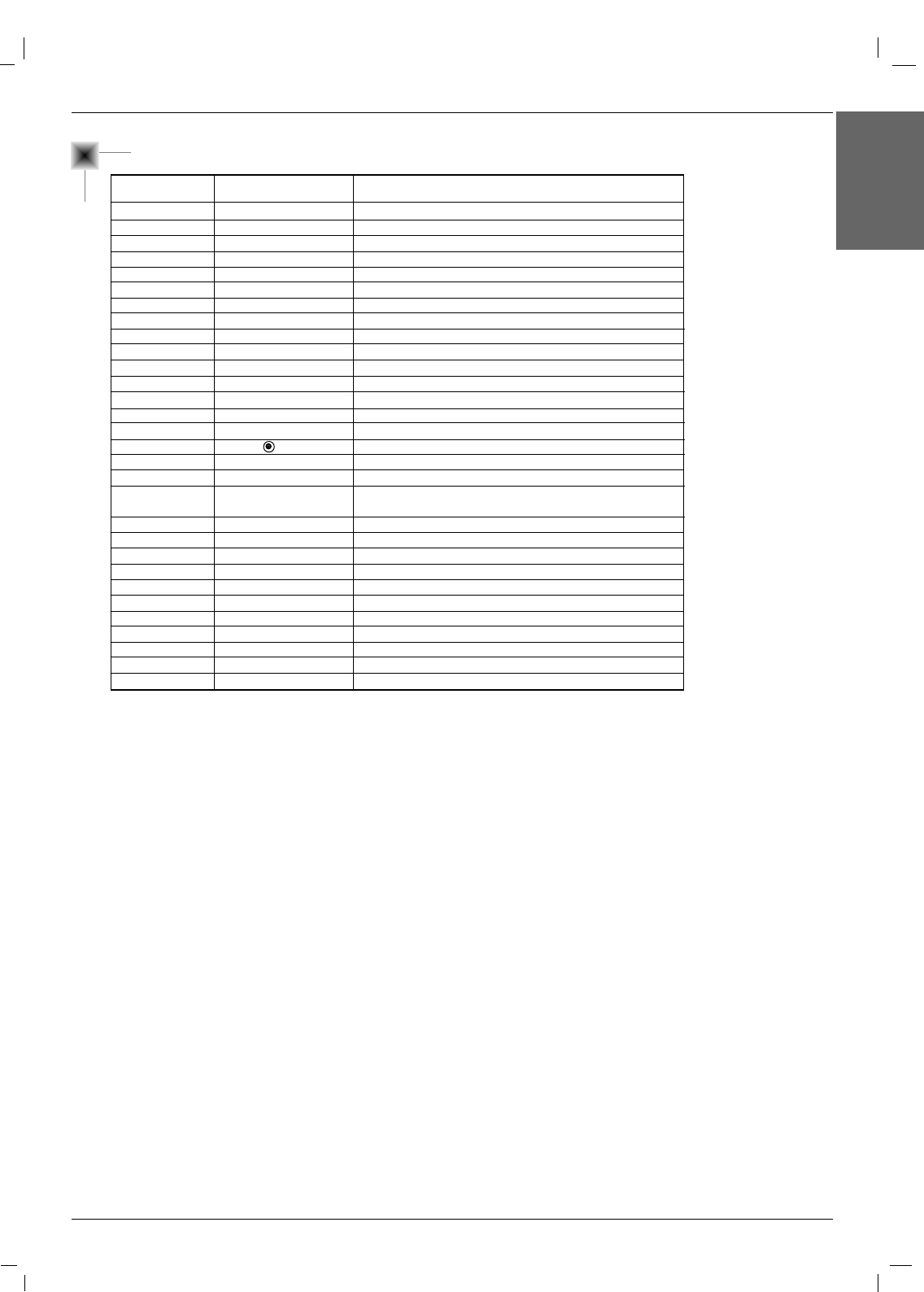
Owner’s Manual 39
ENGLISH
IR Code
Number Key 0
Number Key 1
Number Key 2
Number Key 3
Number Key 4
Number Key 5
Number Key 6
Number Key 7
Number Key 8
Number Key 9
SLEEP
MUTE
POWER
VOL+
VOL-
SET ( )
AII INPUT SELECT
MENU
ARC
F
G
D
E
EXIT
Auto config.
Input video
Input Component 1
Input Component 2
Input RGB
Input HDMI/DVI
10
11
12
13
14
15
16
17
18
19
0E
09
08
02
03
44
0B
43
79
07
06
40
41
5B
99
5A
BF
D4
D5
C6
R/C Button
R/C Button
R/C Button
R/C Button
R/C Button
R/C Button
R/C Button
R/C Button
R/C Button
R/C Button
R/C Button
R/C Button
R/C Button (Power On/Off)
Discrete IR Code
Discrete IR Code
R/C Button
R/C Button
R/C Button
R/C Button (Spectacle,Full, Original, 4:3, 16:9, 1:1,
14:9, Zoom1, 2 mode Selection)
R/C Button
R/C Button
R/C Button
R/C Button
R/C Button
Discrete IR Code (Only RGB mode)
Discrete IR Code (Input Video Selection)
Discrete IR Code (Input Component 1 Selection)
Discrete IR Code (Input Component 2 Selection)
Discrete IR Code (Input RGB Selection)
Discrete IR Code (Input HDMI/DVI Selection)
Code (Hexa) Function Note
40 Plasma Monitor
Troubleshooting Checklist
No output from one of
the speakers • Adjust Balance in the Sound menu.
Unusual sound from
inside the monitor
• A change in ambient humidity or temperature may result in an unusual noise
when the plasma display is turned on or off and does not indicate a fault with
the monitor.
No picture &
No sound
•Check whether the Monitor is turned on.
• Power cord inserted into wall outlet?
• Test the wall power outlet, plug other product’s power cord into the wall outlet
where the Monitor’s power cord was plugged in.
No or Poor colour
or Poor picture
• Select Colour in the Picture menu and press the Gbutton.
• Keep a sufficient distance between the Monitor and the VCR.
• Activate any function to restore the brightness of the picture.
(If still picture is on the screen for more than 5 minutes, the screen gets dark.)
The remote control
doesn’t work
•Check to see if there is any object between the Plasma Display and the
remote control causing obstruction.
• Are batteries installed with correct polarity (+ to +, - to -)?
• Install new batteries.
Picture OK &
No sound
•Press the VOLUME ( G) button.
• Sound muted? Press MUTE button.
Picture appears slowly
after switching on
•This is normal, the image is muted during the plasma display startup process.
Please contact your service center, if the picture has not appeared after five
minutes.
Horizontal/vertical bars
or picture shaking •Check for local interference such as an electrical appliance or power tool.
T
Troubleshooting Checklist
roubleshooting Checklist
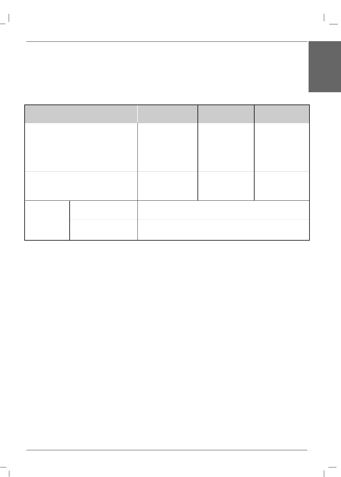
Owner’s Manual 41
ENGLISH
Product Specifications
Product Specifications
Product Specifications
MODELS
Width (inches / mm)
Height (inches / mm)
Depth (inches / mm)
Weight (pounds / kg)
Power requirement
Resolution
Environmental
condition
Operating Temperature
Operating Humidity
Storage Temperature
Storage Humidity
42 / 1066
25.6 / 650
3.9 / 97.5
62.8 / 28.5
49.3 / 1253
29.3 / 745
4.3 / 109.5
85.5 / 38.8
42PM4M
(42PM4M-WA)
(42PM4MA-WA)
50PM4M
(50PM4M-WA)
(50PM4MA-WA)
AC100-240V~ 50/60Hz 3.3A
1024x 768 (Dot)
AC100-240V~ 50/60Hz 4.5A
1365 x 768 (Dot)
56.9 / 1455
34.8 / 883
4.5 / 112
130.5 / 59.2
60PM4M
(60PM4M-WA)
(60PM4MA-WA)
AC100-240V~ 50/60Hz 5.8A
1366 x 768 (Dot)
32 ~ 140°F (0 ~ 60°C)
Less than 80%
-4 ~ 140°F (-20 ~ 60°C)
Less than 90%
• The specifications shown above may change without notice for quality improvement.