LG Electronics USA 60PZ750UA Plasma Monitor User Manual PZ5 7 1007
LG Electronics USA Plasma Monitor PZ5 7 1007
Contents
- 1. User Manual part 1 of 2
- 2. User Manual part 2 of 2
User Manual part 1 of 2

P/NO : SAC34134203 (1010-REV09) www.lg.com
The model and serial number of the TV is located
on the back and/or one side of the TV.
Record it below should you ever need service.
MODEL
SERIAL
OWNER’S MANUAL
LED LCD TV / LCD TV
PLASMA TV
Please read this manual carefully before operating
your set and retain it for future reference.
LCD TV MODELS
32LD550
42LD550
46LD550
52LD550
60LD550
47LD650
55LD650
LED LCD TV MODELS
32LE5400
42LE5400
47LE5400
55LE5400
42LE5350
47LE5350
42LE5500
47LE5500
55LE5500
42LE7500
47LE7500
55LE7500
47LE8500
55LE8500
42LX6500
47LX6500
55LX6500
PLASMA TV MODELS
50PK750
60PK750
50PZ750
60PZ750
50PZ540
60PZ540
50PZ550
60PZ550
2
WARNING / CAUTION
The lightning flash with arrowhead
symbol, within an equilateral trian-
gle, is intended to alert the user to
the presence of uninsulated “dan-
gerous voltage” within the product’s enclo-
sure that may be of sufficient magnitude to
constitute a risk of electric shock to persons.
The exclamation point within an equi-
lateral triangle is intended to alert
the user to the presence of important oper-
ating and maintenance (servicing) instruc-
tions in the literature accompanying the
appliance.
TO REDUCE THE RISK OF ELECTRIC
SHOCK DO NOT REMOVE COVER (OR
BACK). NO USER SERVICEABLE PARTS
INSIDE. REFER TO QUALIFIED SERVICE
PERSONNEL.
WARNING/CAUTION
TO REDUCE THE RISK OF FIRE AND
ELECTRIC SHOCK, DO NOT EXPOSE THIS
PRODUCT TO RAIN OR MOISTURE.
NOTE TO CABLE/TV INSTALLER
This reminder is provided to call the CATV system
installer’s attention to Article 820-40 of the National
Electric Code (U.S.A.). The code provides guide-
lines for proper grounding and, in particular, speci-
fies that the cable ground shall be connected to the
grounding system of the building, as close to the
point of the cable entry as practical.
WARNING / CAUTION
To prevent fire or shock hazards, do not expose
this product to rain or moisture.
FCC Notice
Class B digital device
This equipment has been tested and found to
comply with the limits for a Class B digital device,
pursuant to Part 15 of the FCC Rules. These
limits are designed to provide reasonable pro-
tection against harmful interference in a residen-
tial installation. This equipment generates, uses
and can radiate radio frequency energy and, if not
installed and used in accordance with the
instructions, may cause harmful interference to
radio communications. However, there is no
guarantee that interference will not occur in a
particular installation. If this equipment does
cause harmful interference to radio or television
reception, which can be determined by turning
the equipment off and on, the user is encour-
aged to try to correct the interference by one or
more of the following measures:
- Reorient or relocate the receiving antenna.
- Increase the separation between the equip-
ment and receiver.
- Connect the equipment to an outlet on a circuit
different from that to which the receiver is con-
nected.
- Consult the dealer or an experienced radio/TV
technician for help.
This device complies with part 15 of the FCC
Rules.
Operation is subject to the following two condi-
tions: (1) This device may not cause (harmful)
interference, and (2) this device must accept
any interference received, including interference
that may cause undesired operation (of the
device).
Any changes or modifications in construction of
this device which are not expressly approved by
the party responsible for compliance could void
the user’s authority to operate the equipment.
CAUTION
Do not attempt to modify this product in any
way without written authorization from LG
Electronics.
Unauthorized modification could void the user’s
authority to operate this product.
3
SAFETY INSTRUCTIONS
IMPORTANT SAFETY INSTRUCTIONS
Read these instructions.
Keep these instructions.
Heed all warnings.
Follow all instructions.
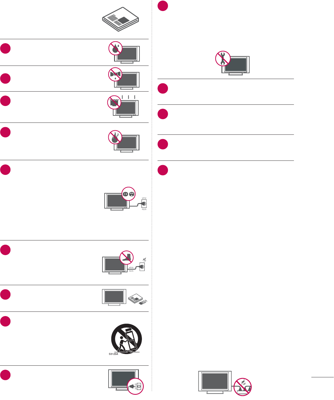
1Do not use this apparatus
near water.
2Clean only with dry cloth.
3Do not block any ventilation
openings. Install in accordance
with the manufacturer’s
instructions.
4
Do not install near any heat
sources such as radiators, heat
registers, stoves, or other appa-
ratus (including amplifiers) that
produce heat.
5
Do not defeat the safety pur-
pose of the polarized or ground-
ing-type plug. A polarized plug
has two blades with one wider
than the other. A grounding
type plug has two blades and a
third grounding prong, The wide
blade or the third prong are
provided for your safety. If the
provided plug does not fit into
your outlet, consult an electri-
cian for replacement of the
obsolete outlet.
6Protect the power cord from
being walked on or pinched
particularly at plugs, conve-
nience receptacles, and the
point where they exit from the
apparatus.
7Only use attachments/acces-
sories specified by the manu-
facturer.
8Use only with the cart, stand,
tripod, bracket, or table speci-
fied by the manufacturer, or
sold with the apparatus. When
a cart is used, use caution
when moving the cart/appara-
tus combination to avoid injury
from tip-over.
9Unplug this apparatus during
lighting storms or when unused
for long periods of time.
10
Refer all servicing to qualified service per-
sonnel. Servicing is required when the appa-
ratus has been damaged in any way, such
as power-supply cord or plug is damaged,
liquid has been spilled or objects have fallen
into the apparatus, the apparatus has been
exposed to rain or moisture, does not oper-
ate normally, or has been dropped.
11
Never touch this apparatus or antenna dur-
ing a thunder or lighting storm.
12
When mounting a TV on the wall, make sure
not to install the TV by the hanging power
and signal cables on the back of the TV.
13
Do not allow an impact shock or any objects
to fall into the product, and do not drop
onto the screen with something.
14
CAUTION concerning the Power Cord:
It is recommend that appliances be placed
upon a dedicated circuit; that is, a single
outlet circuit which powers only that appli-
ance and has no additional outlets or
branch circuits. Check the specification
page of this owner's manual to be certain.
Do n ot connect too many appliances to the
same AC power outlet as this could result in
fire or electric shock.
Do not overload wall outlets. Overloaded
wall outlets, loose or damaged wall outlets,
extension cords, frayed power cords, or
damaged or cracked wire insulation are
dangerous . Any of these conditions could
result in electric shock or fire. Periodically
examine the cord of your appliance, and if its
appearance indicates damage or deteriora-
tion, unplug it, discontinue use of the appli-
ance, and have the cord replaced with an
exact replacement part by an authorized
servicer. Protect the power cord from phys-
ical or mechanical abuse, such as being
twisted, kinked, pinched, closed in a door, or
walked upon. Pay particular attention to
plugs, wall outlets, and the point where the
cord exits the appliance.
Do not make the TV with the power cord
plugged in. Do not use a damaged or loose
power cord. Be sure do grasp the plug
when unplugging the power cord. Do not
pull on the power cord to unplug the TV.
4
SAFETY INSTRUCTIONS
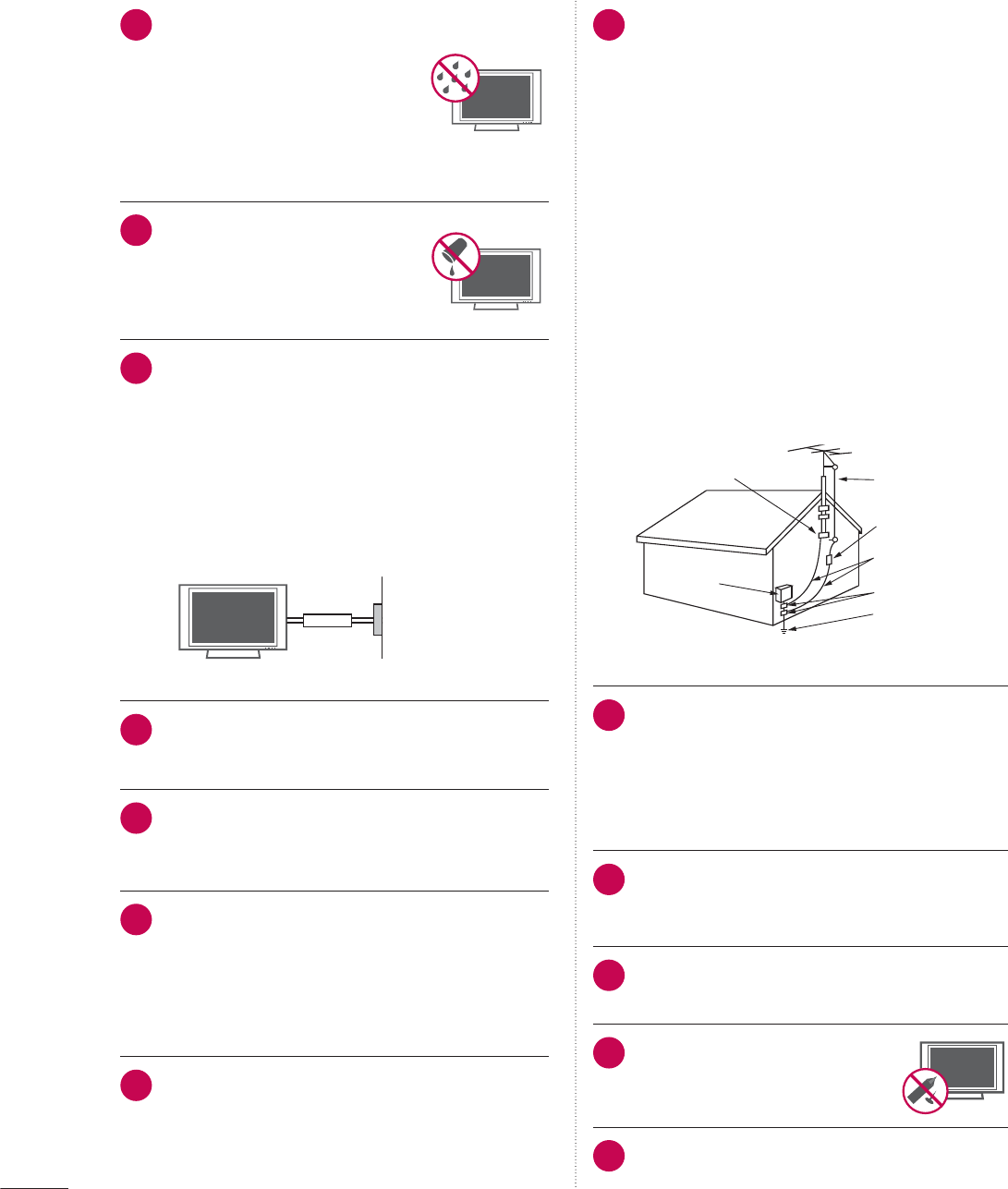
15
WARNING - To reduce the risk of
fire or electrical shock, do not
expose this product to rain,
moisture or other liquids. Do not
touch the TV with wet hands. Do
not install this product near
flammable objects such as gas-
oline or candles or expose the
TV to direct air conditioning.
16
Do not expose to dripping or
splashing and do not place
objects filled with liquids, such
as vases, cups, etc. on or over
the apparatus (e.g. on shelves
above the unit).
17
GROUNDING
Ensure that you connect the earth ground wire
to prevent possible electric shock (i.e. a TV with
a three-prong grounded AC plug must be con-
nected to a three-prong grounded AC outlet). If
grounding methods are not possible, have a
qualified electrician install a separate circuit
breaker.
Do not try to ground the unit by connecting it to
telephone wires, lightening rods, or gas pipes.
Power
Supply
Short-circuit
Breaker
18
DISCONNECTING DEVICE FROM MAINS
Mains plug is the disconnecting device. The
plug must remain readily operable.
19
As long as this unit is connected to the AC
wall outlet, it is not disconnected from the AC
power source even if you turn off this unit by
SWITCH.
20
Cleaning
When cleaning, unplug the power cord and
scrub gently with a soft cloth to prevent
scratching. Do not spray water or other liquids
directly on the TV as electric shock may
occur. Do not clean with chemicals such as
alcohol, thinners or benzene.
21
Moving
Make sure the product is turned off, unplugged
and all cables have been removed. It may
take 2 or more people to carry larger TVs. Do
not press against or put stress on the front
panel of the TV.
22
ANTENNAS
Outdoor antenna grounding
If an outdoor antenna is installed, follow the
precautions below. An outdoor antenna sys-
tem should not be located in the vicinity of
overhead power lines or other electric light
or power circuits, or where it can come in
contact with such power lines or circuits as
death or serious injury can occur.
Be sure the antenna system is grounded so
as to provide some protection against volt-
age surges and built-up static charges.
Section 810 of the National Electrical Code
(NEC) in the U.S.A. provides information
with respect to proper grounding of the
mast and supporting structure, grounding
of the lead-in wire to an antenna discharge
unit, size of grounding conductors, location
of antenna discharge unit, connection to
grounding electrodes and requirements for
the grounding electrode.
Antenna grounding according to the
National Electrical Code, ANSI/NFPA 70
Antenna Lead in Wire
Antenna Discharge Unit
(NEC Section 810-20)
Grounding Conductor
(NEC Section 810-21)
Ground Clamps
Power Service Grounding
Electrode System (NEC
Art 250, Part H)
Ground Clamp
Electric Service
Equipment
NEC: National Electrical Code
23
Ventilation
Install your TV where there is proper ventila-
tion. Do not install in a confined space such
as a bookcase. Do not cover the product
with cloth or other materials (e.g.) plastic
while plugged in. Do not install in exces-
sively dusty places.
24
Take care not to touch the ventilation open-
ings. When watching the TV for a long
period, the ventilation openings may
become hot.
25
If you smell smoke or other odors coming
from the TV, unplug the power cord contact
and authorized service center.
26
Do not press strongly upon the
panel with hand or sharp object
such as nail, pencil or pen, or
make a scratch on it.
27
Keep the product away from direct sunlight.

5
28
Dot Defect
The Plasma or LCD panel is a high technol-
ogy product with resolution of two million to
six million pixels. In a very few cases, you
could see fine dots on the screen while
you’reviewing the TV. Those dots are deacti-
vated pixels and do not affect the perfor-
mance and reliability of the TV.
29
Generated Sound
“Cracking” noise: A cracking noise that occurs
when watching or turning off the TV is gener-
ated by plastic thermal contraction due to
temperature and humidity. This noise is com-
mon for products where thermal deformation
is required.
Electrical circuit humming/panel buzzing: A
low level noise is generated from a high-speed
switching circuit, which supplies a large amount
of current to operate a product. It varies
depending on the product.
This generated sound does not affect the
performance and reliability of the product.
30
For LED LCD TV/LCD TV
If the TV feels cold to the touch, there may be
a small “flicker” when it is turned on. This is
normal, there is nothing wrong with TV.
Some minute dot defects may be visible on
the screen, appearing as tiny red, green, or
blue spots. However, they have no adverse
effect on the monitor’s performance.
Avoid touching the LCD screen or holding your
finger(s) against it for long periods of time.
Doing so may produce some temporary dis-
tortion effects on the screen.
31
Viewing 3D Imaging (For 3D TV)
ŹWhen viewing 3D imaging, watch the
TV from an effective viewing angle and
within the appropriate distance. If you ex-
ceed this viewing angle or distance, you
may not be able to view the 3D imaging.
Furthermore, the 3D imaging may not
display if it is viewed while you are lying
down.
ŹIf you watch the 3D imaging too closely
or for a long period of time, it may harm
your eyesight.
ŹWatching the TV or playing video games
that incorporate 3D imaging with the
3D glasses for a long period of time can
cause drowsiness, headaches or fatigue
to you and/or your eyes. If you have a
headache, or otherwise feel fatigued or
drowsy, stop watching the TV and take a
rest.
ŹPregnant woman, seniors, persons with
heart problems or persons who experi-
ence frequent drowsiness should refrain
from watching 3D TV.
ŹSome 3D imaging may cause you to duck
or dodge the image displayed in the video.
Therefore, it is best if you do not watch 3D
TV near fragile objects or near any objects
that can be knocked over easily.
Ź Please prevent children under the age of
5 from watching 3D TV. It may affect their
vision development.
ŹWarning for photosensitization seizure:
Some viewers may experience a seizure
or epilepsy when exposed to certain fac-
tors, including flashing lights or images
in TV or video games. If you or anybody
from your family has a history of epilepsy
or seizure, please consult with your doc-
tor before watching 3D TV.

6
Also certain symptoms can occur in un-
specified conditions without any previ-
ous history. If you experience any of the
following symptoms, immediately stop
watching the 3D imaging and consult a
doctor: dizziness or lightheadedness, vi-
sual transition or altered vision, visual or
facial instability, such as eye or muscle
twitching, unconscious action, convulsion,
loss of conscience, confusion or disorien-
tation, loss of directional sense, cramps,
or nausea. Parents should monitor their
children, including teenagers, for these
symptoms as they may be more sensitive
to the effects of watching 3D TV.
Risk of photosensitization seizure can be
reduced with the following actions.
- Take frequent breaks from watching 3D
TV.
- For those who have vision that is differ-
ent in each eye, they should watch the
TV after taking vision correction mea-
sures.
- Watch the TV so that your eyes are on
the same level as the 3D screen and
refrain from sitting too closely to the TV
- Do not watch the 3D imaging when
tired or sick, and avoid watching the 3D
imaging for a long period of time.
- Do not wear the 3D glasses for any oth-
er purpose than viewing 3D imaging on
a 3D TV.
- Some viewers may feel disoriented after
watching 3D TV. Therefore, after you watch
3D TV, take a moment to regain aware-
ness of your situation before moving.
ON DISPOSAL
(Only Hg lamp used LCD TV)
The fluorescent lamp used in this product con-
tains a small amount of mercury. Do not
dispose of this product with general house-
hold waste. Disposal of this product must be
carried out in accordance to the regulations of
your local authority.
SAFETY INSTRUCTIONS

7
WARNING / CAUTION
............................2
SAFETY INSTRUCTIONS
........................3
CONTENTS
......................................................6
FEATURE OF THIS TV
..............................9
PREPARATION
Accessories...........................................................10
Optional Extras ..................................................... 11
Front Panel Information .................................... 12
Back Panel Information..................................... 17
Stand Instructions
.....................................................20
VESA Wall Mounting ........................................26
Cable Management ..........................................28
Desktop Pedestal Installation ..........................31
Swivel Stand ......................................................... 31
Attaching the TV to a Desk ............................32
Kensington Security System ..........................32
Securing the TV to the wall to prevent falling
when the tv is used on a stand.....................33
Antenna or Cable Connection.......................34
EXTERNAL EQUIPMENT SETUP
HD Receiver Setup............................................35
DVD SETUP.........................................................39
VCR SETUP.........................................................42
Other A/V Source Setup.................................44
USB Connection ................................................45
Headphone Setup
....................................................46
Audio Out Connection..................................... 47
External Equipment WIreless Connection
(Optional Extras).................................................48
PC Setup..............................................................49
Network Setup ....................................................55
WATCHING TV / CHANNEL CONTROL
Remote Control Functions ..............................63
Turning on the TV..............................................66
Channel Selection..............................................66
Volume Adjustment ..........................................66
Initial Setting ....................................................... 67
On-Screen Menus Selection ..........................69
Quick Menu .......................................................... 71
Customer Support
- Software Update............................................. 72
- Picture Test/Sound Test................................ 73
- Product/Service Info...................................... 74
- Network Test..................................................... 74
Simple Manual.................................................... 75
Channel Setup
- Auto Scan (Auto Tuning).............................. 76
- Add/Delete Channel (Manual Tuning) ..... 77
- Channel Editing............................................... 78
Favorite Channel Setup.................................... 79
Favorite Channel List ........................................ 79
Channel List ....................................................... 80
Channel Information .......................................... 81
Channel Brief Information...............................82
Input List ..............................................................83
Input Label...........................................................84
Reset to Factory Default (Initial Setting).....85
Mode Setting ......................................................86
Demo Mode ........................................................ 87
AV Mode...............................................................88
Game.....................................................................89
SIMPLINK.............................................................90
3D VIDEO
3D Video...............................................................92
MY MEDIA
Entry Mode ..........................................................96
Connection Method .......................................... 97
Movie list............................................................. 102
Photo list............................................................. 109
Music list.............................................................. 115
DivX Registration Code.................................. 120
Deactivation ........................................................ 121
NETWORK
Legal Notice ...................................................... 122
CONTENTS

8
NETCAST
Netcast Menu.................................................... 123
YOUTUBE........................................................... 124
PICASA............................................................... 126
PICTURE CONTROL
Picture Size (Aspect Ratio) Control............ 128
Picture Wizard................................................... 130
ᰚEnergy Saving ............................................ 132
Preset Picture Settings (Picture Mode)..... 133
Manual Picture Adjustment - User Mode 134
Picture Improvement Technology (Advanced
Control) ............................................................... 135
Expert Picture control..................................... 136
Picture Reset..................................................... 139
TruMotion .........................................................140
LED Local Dimming ........................................141
Power Indicator ................................................ 142
Image Sticking Minimization (ISM) Method
.143
SOUND & LANGUAGE CONTROL
Auto Volume...................................................... 144
Clear Voice II ..................................................... 145
Balance ............................................................... 146
Preset Sound Settings (Sound Mode) .......147
Sound Setting Adjustment - User Mode. 148
Audio Reset....................................................... 149
TV Speakers On/Off Setup .......................... 150
Stereo/SAP Broadcast Setup ....................... 151
Audio Language ............................................. 152
On-screen Menus Language Selection.... 153
Caption Mode
- Analog Broadcasting System Captions. 154
- Digital Broadcasting System Captions... 155
- Caption Option.............................................. 156
TIME SETTING
Clock Setting
- Auto Clock Setup..........................................157
- Manual Clock Setup .................................... 158
Auto On/Off Time Setting ............................ 159
Sleep Timer Setting ........................................ 160
PARENTAL CONTROL / RATINGS
Set Password & Lock System
- Setting up Your Password ............................161
- Set Password ................................................. 162
- Lock System................................................... 163
Channel Blocking............................................. 164
Movie & TV Rating .......................................... 165
Downloadable Rating.......................................170
External Input Blocking ....................................171
Key Lock..............................................................172
APPENDIX
Troubleshooting.................................................173
Maintenance.......................................................176
Product Specifications ....................................177
IR Codes............................................................. 182
External Control Through RS-232C .......... 184
Open Source License..................................... 190
9
FEATURE OF THIS TV
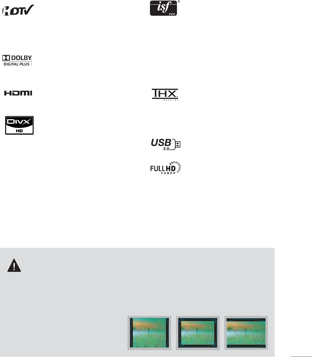
IMPORTANT INFORMATION TO PREVENT “IMAGE
BURN / BURN-IN” ON YOUR TV SCREEN
ᯫ
Some of these features are not available on all models.
This TV contains the detailed calibra-
tions necessary for professional certifi-
cation by the Imaging Science
Foundation. The resulting ISF “day” and
“night” modes will then be accessible
by the user to experience the best their
LG HDTV has to offer.
Sophisticated and detailed calibrations
can be made through the ISFccc mode.
Detailed calibration requires a licensed
technician.
Please contact your local dealer to
inquire about an ISF certified technician.
THX (Thomlinson Holman’s Experiment)
is an audio and video certification stan-
dard established by George Lucas and
Thomlinson. A THX certified display
guarantees screen quality that exceeds
the display standard specification in
both hardware and software.
View videos and photos and listen to
music on your TV through USB 2.0
(‘videos’ dependent on model).
Displays HDTV programs in full 1920 x
1080p resolution for a more detailed
picture.
ᯫ
When a fixed image (e.g. logos, screen menus, video game, and computer display) is displayed
on the TV for an extended period, it can become permanently imprinted on the screen. This
phenomenon is known as “image burn” or “burn-in.” Image burn is not covered under the man-
ufacturer’s warranty.
ᯫ
In order to prevent image burn, avoid displaying a fixed image on your TV screen for a prolonged
period (2 or more hours for LCD, 1 or more
hours for Plasma).
ᯫ
Image burn can also occur on the letter-
boxed areas of your TV if you use the 4:3
aspect ratio setting for an extended period.
High-definition television. High-
resolution digital television broadcast
and playback system composed of
roughly a million or more pixels, 16:9
aspect-ratio screens, and AC3 digital
audio. A subset of digital television,
HDTV formats include 1080p, 1080i,
and 720p resolutions.
Manufactured under license from Dolby
Laboratories. “Dolby “and the double-D
symbol are trademarks of Dolby
Laboratories.
HDMI, the HDMI logo and High-
Definition Multimedia Interface are
trademarks or registered trademarks of
HDMI Licensing LLC."
ABOUT DIVX VIDEO: DivX® is a digital
video format created by DivX,Inc. This is
an official DivX Certified device that
plays DivX video. Visit www.divx.com for
more information and software tools to
convert your files into DivX video.
ABOUT DIVX VIDEO-ON-DEMAND:
This DivX Certified® device must be
registered in order to play DivX Video-
on-Demand (VOD) content. To gener-
ate the registration code, locate the
DivX VOD section in the device setup
menu. Go to vod.divx.com with this
code to complete the registration pro-
cess and learn more about DivX VOD.
“DivX Certified® to play DivX® video up
to HD 1080p, including premium con-
tent”
“DivX®, DivX Certified® and associated
logos are registered trademarks of
DivX, Inc. and are used under license.”
Pat. 7,295,673; 7,460,668; 7,515,710;
7, 51 9, 2 74
PREPARATION
PREPARATION
10
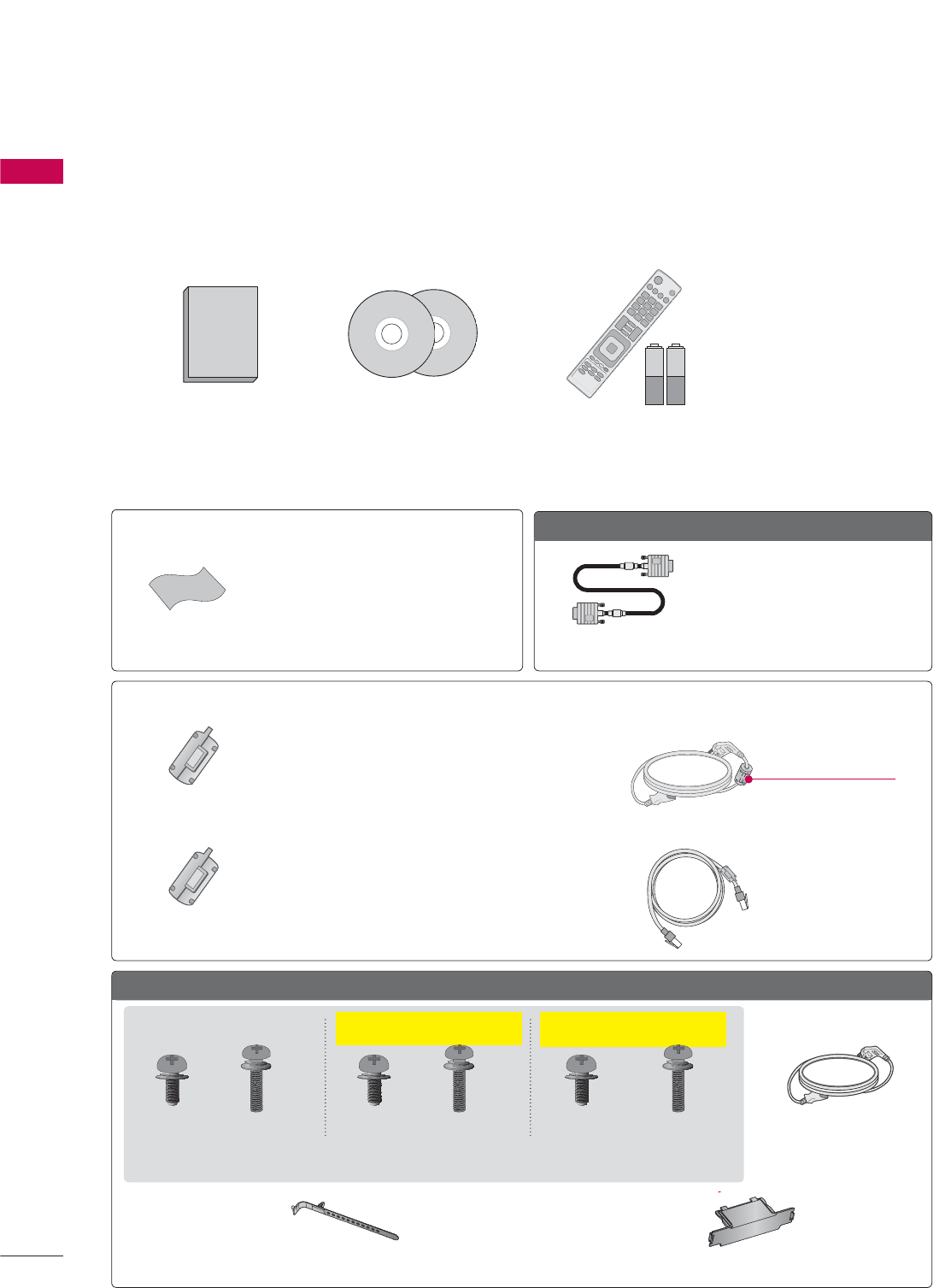
ACCESSORIES
PREPARATION
Ensure that the following accessories are included with your TV. If an accessory is missing, please con-
tact the dealer where you purchased the TV.
The accessories included may differ from the images below.
Option Extras
* Wipe spots on the exterior only with the
polishing cloth.
* Do not wipe roughly when removing
stains. Excessive pressure may cause
scratches or discoloration.
Polishing Cloth
Not included with all models
Not included with all models
D-sub 15 pin Cable
When using the VGA (D-sub 15
pin cable) PC connection, the user
must use shielded signal interface
cables with ferrite cores to main-
tain standards compliance.
1.5V 1.5V
Owner’s Manual CD Manual,
Nero MediaHome 4
Essentials CD
Remote Control,
Batteries (AAA)
Plasma TV
(For 50PK750) (50PZ540, 50PZ550,
50PZ750)
(For 60PZ540, 60PZ550,
60PZ750)
Protection Cover
(Refer to p.21)
Cable Holder
(Refer to p.28)
x 2
x 3 x 3 x 4x 4 x 4 x 4
Screws for stand assembly (Refer to P.20)
(M5 x 14) (M5 x 14) (M5 x 14)(M4 x 28) (M4 x 26) (M4 x 28)
Ferrite Core
(Black)
Ferrite Core
(White)
Close to the wall plug.
Ferrite core can be used to reduce the electromagnetic
waves that may interfere with the TV. Install the Ferrite
core on the power cable close to the wall plug.
Ferrite core can be used to reduce the electromagnetic
wave when connecting the LAN cable. Place the ferrite
core far from TV and wind the LAN cable in the ferrite
core once.
Power Cord
11
PREPARATION
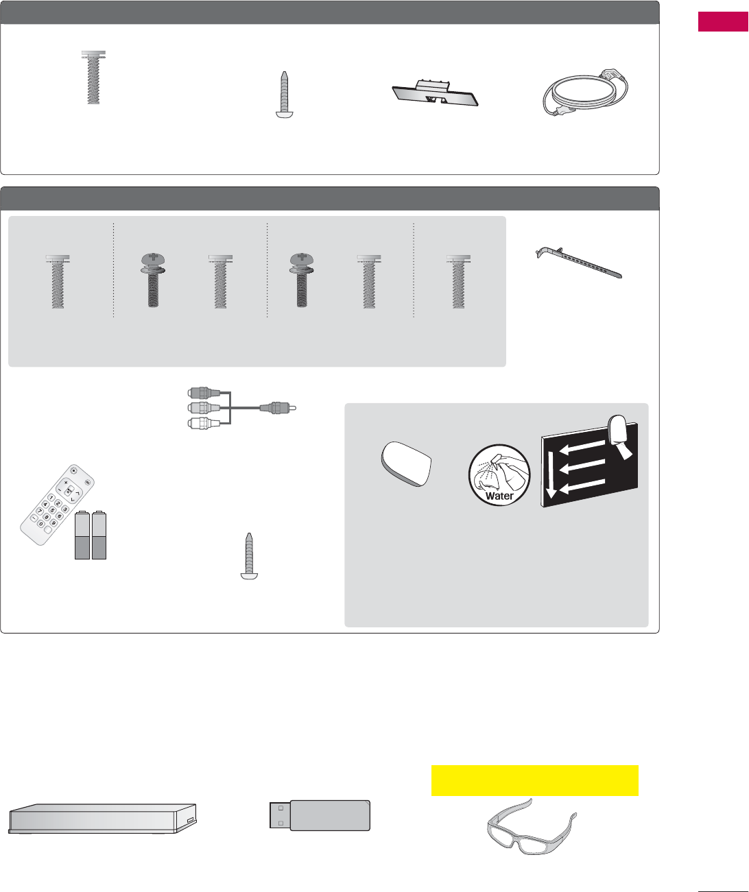
OPTIONAL EXTRAS
Optional extras can be changed or modified for quality improvement without any notification.
Contact your dealer for buying these items.
This device only works with compatible LG LED LCD TV, LCD TV, or Plasma TV.
32/42/46/52/60LD550, 47/55LD650
Protection Cover
(Refer to P.23)
Power Cord
Wireless Media Box
(AN-WL100W)
Wireless LAN for Broadband/
DLNA Adaptor
(AN-WF100)
(M4 x 20)
Screws for stand assembly
(Refer to P.22)
Screw for stand fixing
(Refer to P.32)
x 8
42/47LE5350, 32/42/47/55LE5400, 42/47/55LE5500, 42/47/55LE7500, 47/55LE8500, 42/47/55LX6500
Cable Holder
(Refer to p.30)
Screws for stand assembly (Refer to P.24)
x 8 x 8x 4 x 4x 4 x 4
Component gender cable,
AV gender cable
x 2
(M4 x 20) (M4 x 16)(M4 x 16) (M4 x 16)(M4 x 24) (M4 x 26)
(47/55LE8500) (Other models)(55LE5400/5500/7500,
55LX6500, 42LE5350)
(47LE5350)
(For 42/47/55LE7500)
(For 32/42LD550)
Screw for stand fixing
(Refer to P.32)
(For 32LE5400)
* Wipe spots on the exterior only with the cleasing cloths.
* Do not wipe roughly when removing stains. Excessive pres-
sure may cause scratches or discoloration.
* For cleaning front frame, please slowly wipe in one direction
after spraying water 1-2 times on cleansing cloths. Please
remove excessive moisture after cleaning. Excessive mois-
ture may cause water stains on the frame.
Simple Remote Control,
Batteries (AAA)
(For 42/47/55LE7500,
47/55LE8500)
1.5V 1.5V
CH
FLASHBK
VOL
POWER TV/INPUT
Cleansing Cloths
(mitt)
(For 42/47/55LX6500, 50/60PZ540,
50/60PZ550, 50/60PZ750)
(Except 42/47LE5350) (Except 42/47LE5350)
3D Glasses
(AG-S100)
PREPARATION
PREPARATION
12
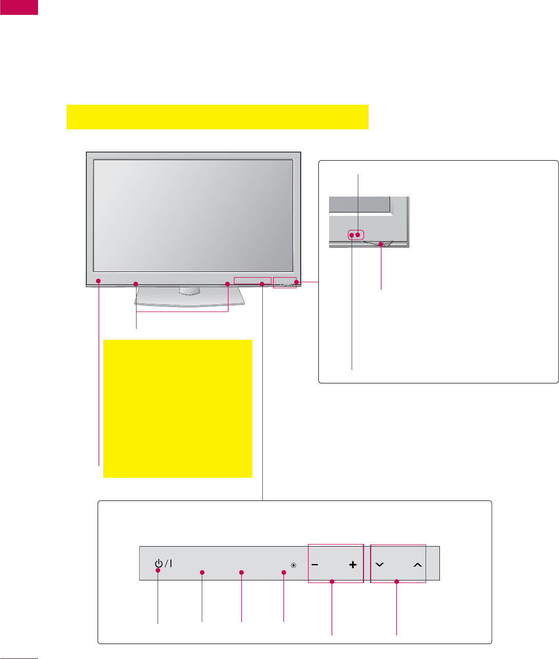
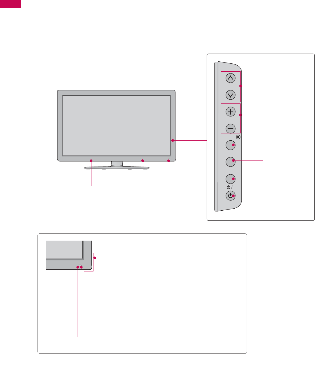
ᯫ
Image shown may differ from your TV.
50/6OK750, 50/60PZ540, 50/60PZ550, 50/60PZ750
FRONT PANEL INFORMATION
SPEAKER
Remote Control Sensor
Intelligent Sensor
Adjusts picture according to the
surrounding conditions
Touch Button
You can operate the button just by touching the button lightly with your finger.
ENTER CH
VOL
MENU
INPUT
CHANNEL
(ᰝ,ᰜ)
Buttons
VOLUME
(-, +)
Buttons
ENTER
Button
MENU
Button
INPUT
Button
POWER
Button
Power/Standby Indicator
Illuminates red in standby mode.
Emitter
(For 50/60PZ540,
50/60PZ550, 50/60PZ750)
It is the part equipped with the
emitter exchanging signal with
3D glasses.
Please be careful not to block
the screen with objects or
people while watching a 3D
Video.
13
PREPARATION
32/42/46/52/60LD550
ENTER
CH
VOL
MENU
INPUT
CHANNEL
(ᰜ,ᰝ) Buttons
VOLUME (+, -)
Buttons
ENTER Button
MENU Button
INPUT Button
POWER Button
Power/Standby Indicator
(Can be adjusted using the Power Indicator
in the OPTION menu.Źp.142)
SPEAKER
Remote Control Sensor
Intelligent Sensor
Adjusts picture according to the
surrounding conditions
PREPARATION
PREPARATION
14
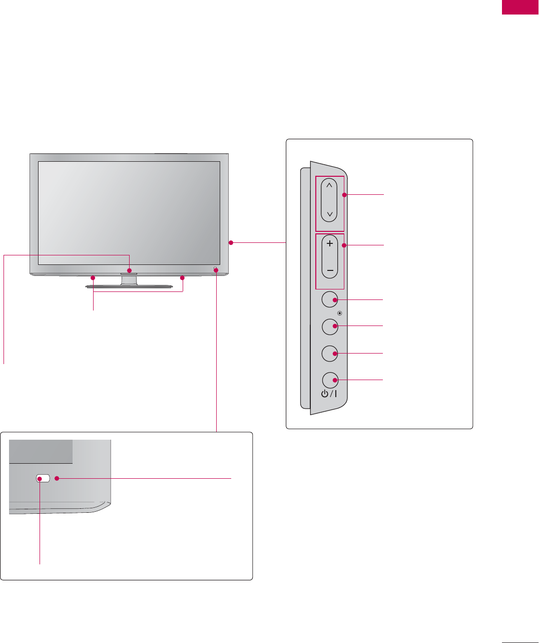
ᯫ
Image shown may differ from your TV.
47/55LD650
SPEAKER
CH
VOL
ENTER
INPUT
MENU
CHANNEL
(ᰜ,ᰝ) Buttons
VOLUME (+, -)
Buttons
ENTER Button
MENU Button
INPUT Button
POWER Button
Remote Control Sensor
Power/Standby Indicator
(Can be adjusted using the Power Indicator
in the OPTION menu.Źp.142)
Intelligent Sensor
Adjusts picture according to the surrounding conditions
15
PREPARATION
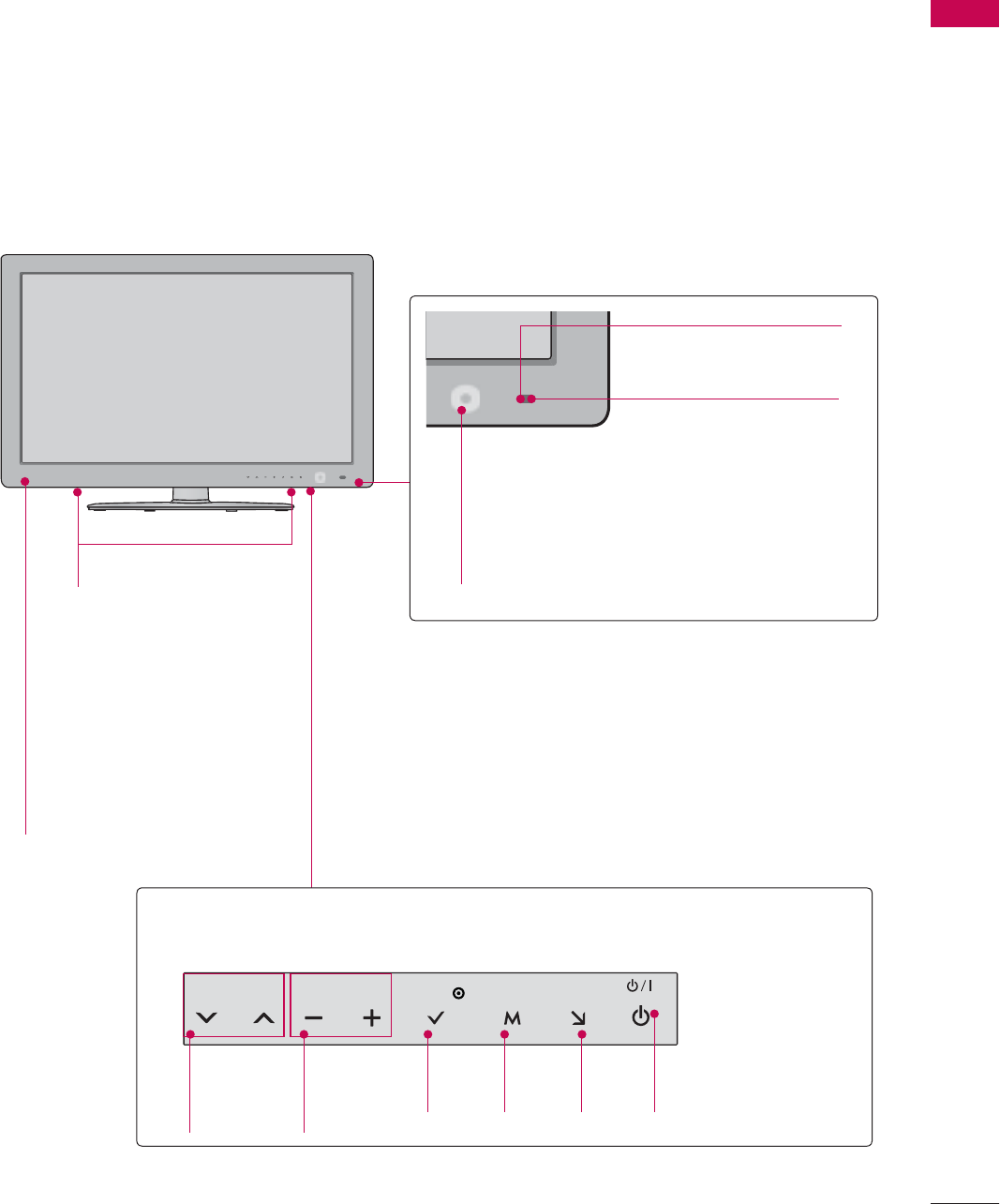
42/47LE5350, 32/42/47/55LE5400, 42/47/55LE5500, 42/47/55LE7500, 42/47/55LX6500
SPEAKER
Power/Standby Indicator
(Can be adjusted using the Power Indicator in
the OPTION menu.Źp.142)
Remote Control Sensor
VOL ENTERCH MENU INPUT
CHANNEL
(ᰝ,ᰜ)
Buttons
VOLUME
(-, +)
Buttons
ENTER
Button
MENU
Button
INPUT
Button
POWER
Button
Touch Button
You can operate the button just by touching the button lightly with your finger.
Intelligent Sensor
Adjusts picture according to
the surrounding conditions
Emitter
(For 42/47/55LX6500)
It is the part equipped with
the emitter exchanging
signal with 3D glasses.
Please be careful not to
block the screen with
objects or people while
watching a 3D Video.
PREPARATION
PREPARATION
16
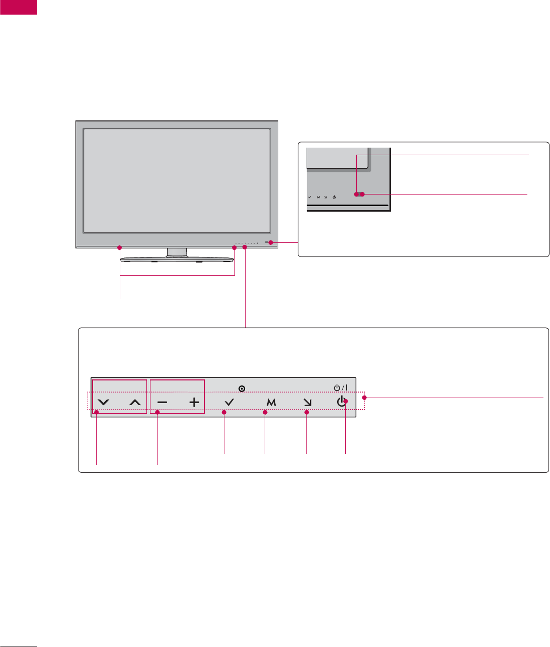
ᯫ
Image shown may differ from your TV.
47/55LE8500
SPEAKER
VOL ENTERCH MENU INPUT
CHANNEL
(ᰝ,ᰜ)
Buttons
VOLUME
(-, +)
Buttons
ENTER
Button
MENU
Button
INPUT
Button
POWER
Button
Touch Button
You can operate the button just by touching the button lightly with your finger.
Remote Control Sensor
Intelligent Sensor
Adjusts picture according to
the surrounding conditions
Power/Standby Indicator
(Can be adjusted using the
Power Indicator in the
OPTION menu.Źp.142)
17
PREPARATION
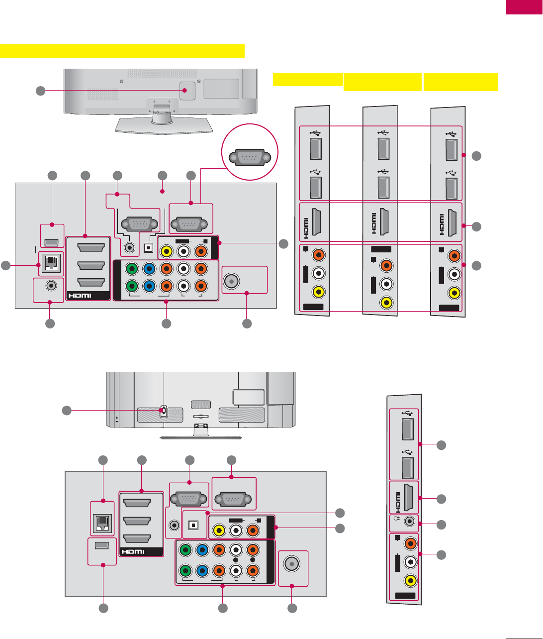
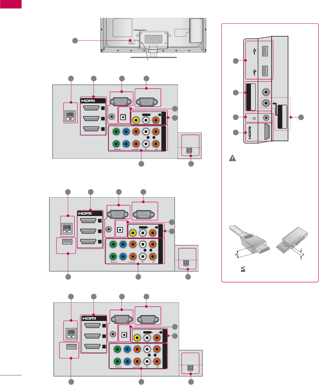
BACK PANEL INFORMATION
ᯫ
Image shown may differ from your TV.
ANTENNA
/CABLE
IN
RGB IN (PC)
LAN
WIRELESS
CONTROL
REMOTE CONTROL IN
AUDIO IN
(RGB/DVI)
O
PTICAL
DIGITAL
AUDIO OUT
/DVI IN
2
3
1
2
1
VIDEO
AUDIO
L(MONO)
R
VIDEO AUDIO
COMPONENT IN
AV IN 1
YLR
P
B
P
R
RS-232C IN
(CONTROL &
SERVICE)
DVI IN 4
USB IN 1 USB IN 2
AV IN 2
VIDEO
AUDIO
L(MONO)
R
4
USB IN 1 USB IN 2
AV IN 2
VIDEO
AUDIO
L(MONO)
R
4
USB IN 1 USB IN 2
AV IN 2
VIDEO
AUDIO
L(MONO)
R
50/60PK750, 50/60PZ550, 50/60PZ750
50/60PK750 50/60PZ75050/60PZ550
1
2 3 45
6
7813
9
12
CABLE MANAGEMENT
AC IN
ANTENNA/
CABLE IN
RGB IN (PC)
LAN
WIRELESS
CONTROL
AUDIO IN
AUDIO OUT
RGB/DVI
RS-232C IN
(
SERVICE ONLY)
OPTICAL DIGITAL
/DVI IN
2
3
1
2
1
VIDEO
AUDIO
L(MONO)
R
VIDEO AUDIO
COMPONENT INAV IN 1
YP
B
P
R
ꔡ
LR
IN 4
H/P USB IN 1 USB IN 2
AV IN 2
VIDEO
AUDIO
L/MONO
R
1
12
2 3 4
5
6
789
32/42/46/52/60LD550, 47/55LD650
10
2
11
6
or
SERVICE ONLY
10
2
6
PREPARATION
PREPARATION
18
12
42/47LE5350, 32/42/47/55LE5400, 42/47/55LE5500, 42/47/55LE7500, 47/55LE8500, 42/47/55LX6500
32/42/47/55LE5400, 42/47/55LE5500, 42/47/55LE7500,
47/55LE8500
42/47/55LX6500
ANTENNA/
CABLE IN
RGB IN (PC)
LAN
WIRELESS
CONTROL
(RGB/DVI)
OPTICAL DIGITAL
/DVI IN
2
3
1
VIDEO
AUDIO
L(MONO)
R
VIDEO AUDIO
COMPONENT INAV IN 1
YP
B
P
R
L R
AUDIO IN
AUDIO OUT
2
1
RS-232C IN
(
SERVICE ONLY)
ꔡ
1 2 3 4
5
6
8 79
COMPONENT IN3
AUDIO / Y P
B
P
R
IN 4
H/P USB IN 1 USB IN 2
AV IN2
VIDEO / AUDIO
10
8
11
2
6
CAUTION
For HDMI IN 4 and USB IN 1, 2
ŹFor an optimal connection,
HDMI cables and USB
devices should have bezels
less than 10 mm (0.39
inches) thick.
*A 10 mm (0.39 inches)
ANTENNA/
CABLE IN
RGB IN (PC)
LAN
WIRELESS
CONTROL
(RGB/DVI)
OPTICAL DIGITAL
/DVI IN
2
3
1
VIDEO
AUDIO
L(MONO)
R
VIDEO AUDIO
COMPONENT INAV IN 1
YP
B
P
R
L R
AUDIO IN
AUDIO OUT
2
1
RS-232C IN
(CONTROL&
SERVICE)
ꔡ
1 2 3 4
5
6
8 79
42/47LE5350
ANTENNA/
CABLE IN
RGB IN (PC)
LAN
(RGB/DVI)
OPTICAL DIGITAL
/DVI IN
2
3
1
VIDEO
AUDIO
L(MONO)
R
VIDEO AUDIO
COMPONENT INAV IN 1
YP
B
P
R
L R
AUDIO IN
AUDIO OUT
2
1
RS-232C IN
(CONTROL&
SERVICE)
1 2 3 4
5
6
8 7

19
PREPARATION
1LAN
Network connection for Netflix, Yahoo! TV
Widgets, etc (for USA).
Also used for video, photo and music files on
a local network.
2HDMI/DVI IN, HDMI IN
Digital Connection.
Supports HD video and Digital audio. Doesn’t
support 480i.
Accepts DVI video using an adapter or HDMI
to DVI cable (not included).
3RGB IN (PC)
Analog PC Connection. Uses a D-sub 15 pin
cable (VGA cable).
AUDIO IN (RGB/DVI)
0.32 cm (1/8 inch) headphone jack for analog
PC audio input.
4RS-232C IN (CONTROL & SERVICE),
SERVICE ONLY, or RS-232C IN (SERVICE
ONLY)
Used by third party devices.
This port is used for service or Hotel mode.
5OPTICAL DIGITAL AUDIO OUT
Digital optical audio output for use with amps
and home theater systems.
Note: In standby mode, this port doesn’t work.
6AV (Audio/Video) IN
Analog composite connection. Supports
standard definition video only (480i).
7ANTENNA/CABLE IN
Connect over-the-air or cable signals to this
jack.
8COMPONENT IN
Analog Connection.
Supports HD.
Uses a red, green, and blue cable for video &
red and white for audio.
9WIRELESS CONTROL
Connect the Wireless Ready Dongle to the TV
to control the external input devices con-
nected to Media Box wirelessly.
10 USB INPUT
Used for viewing photos, watching movies
and listening to MP3s.
11 HEADPHONE
0.32 cm (1/8 inch) headphone jack
Impedance 16 Ω , Maximum audio out 15 mW
12 Power Cord or Socket
For operation with AC power.
Caution: Never attempt to operate the TV on
DC power.
13 REMOTE CONTROL IN
For a wired remote control.
50/60PZ540
PREPARATION
PREPARATION
20
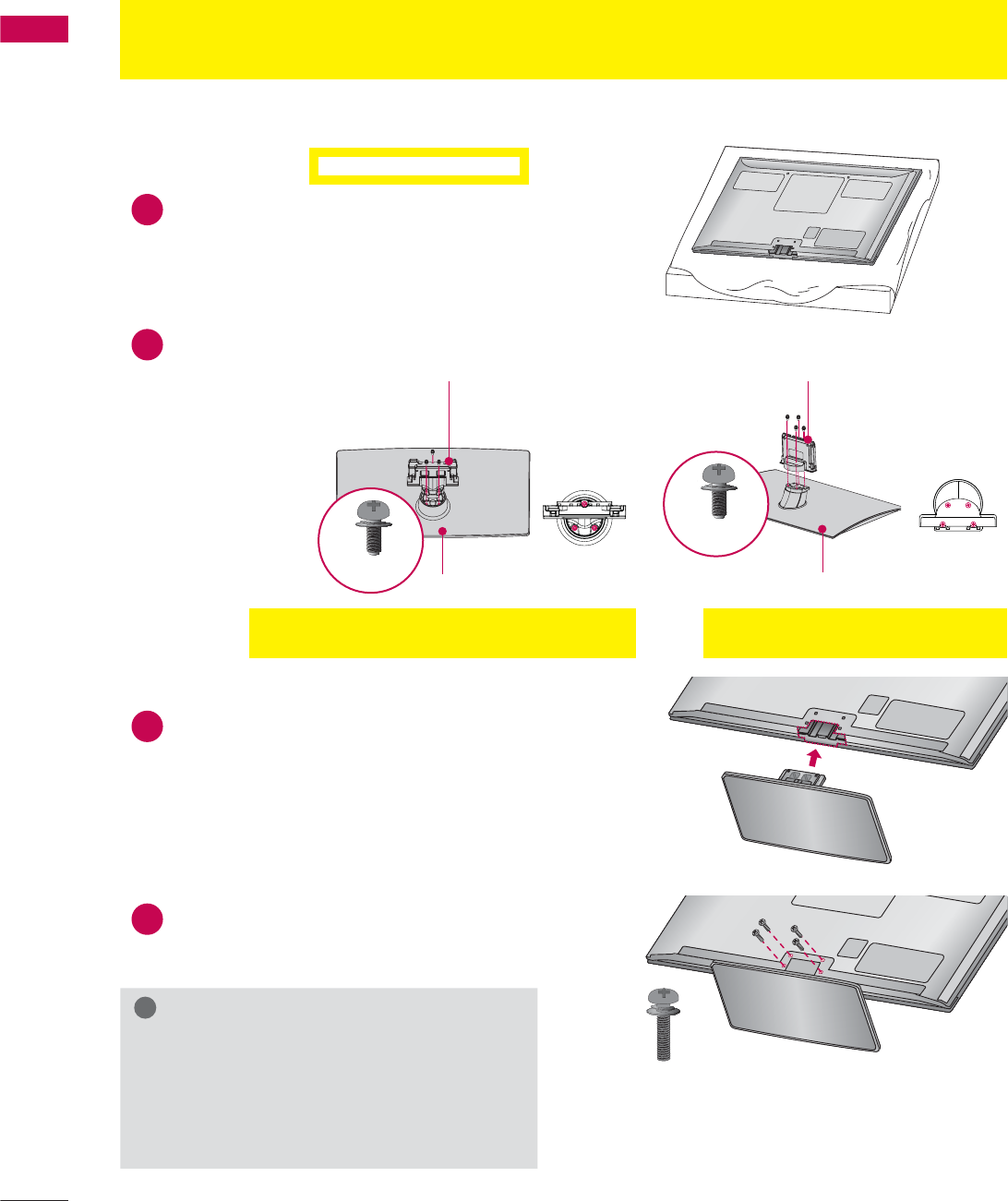
STAND INSTRUCTIONS
(For 50/60PK750, 50/60PZ540, 50/60PZ550, 50/60PZ750)
ᯫ
Image shown may differ from your TV.
INSTALLATION
!
NOTE
ŹWhen assembling the desk type stand,
make sure the screws are fully tightened (If
not tightened fully, the TV can tilt forward
after the product installation). Do not over
tighten.
1Carefully place the TV screen side down on
a cushioned surface to protect the screen
from damage.
2Assemble the parts of the STAND BODY
with the STAND BASE of the TV.
3Assemble the TV as shown.
4Install the 4 screws into the holes shown.
STAND BASE STAND BASE
STAND BODY STAND BODY
M5 x 14
M5 x 14
50PK750, 50PZ540, 50PZ550, 50PZ750
(provided as parts of the product)
60PZ540, 60PZ550, 60PZ750
(provided as parts of the product)
M4 x 26
(50PZ540/550/750)
M4 x 28
(Other models)
21
PREPARATION
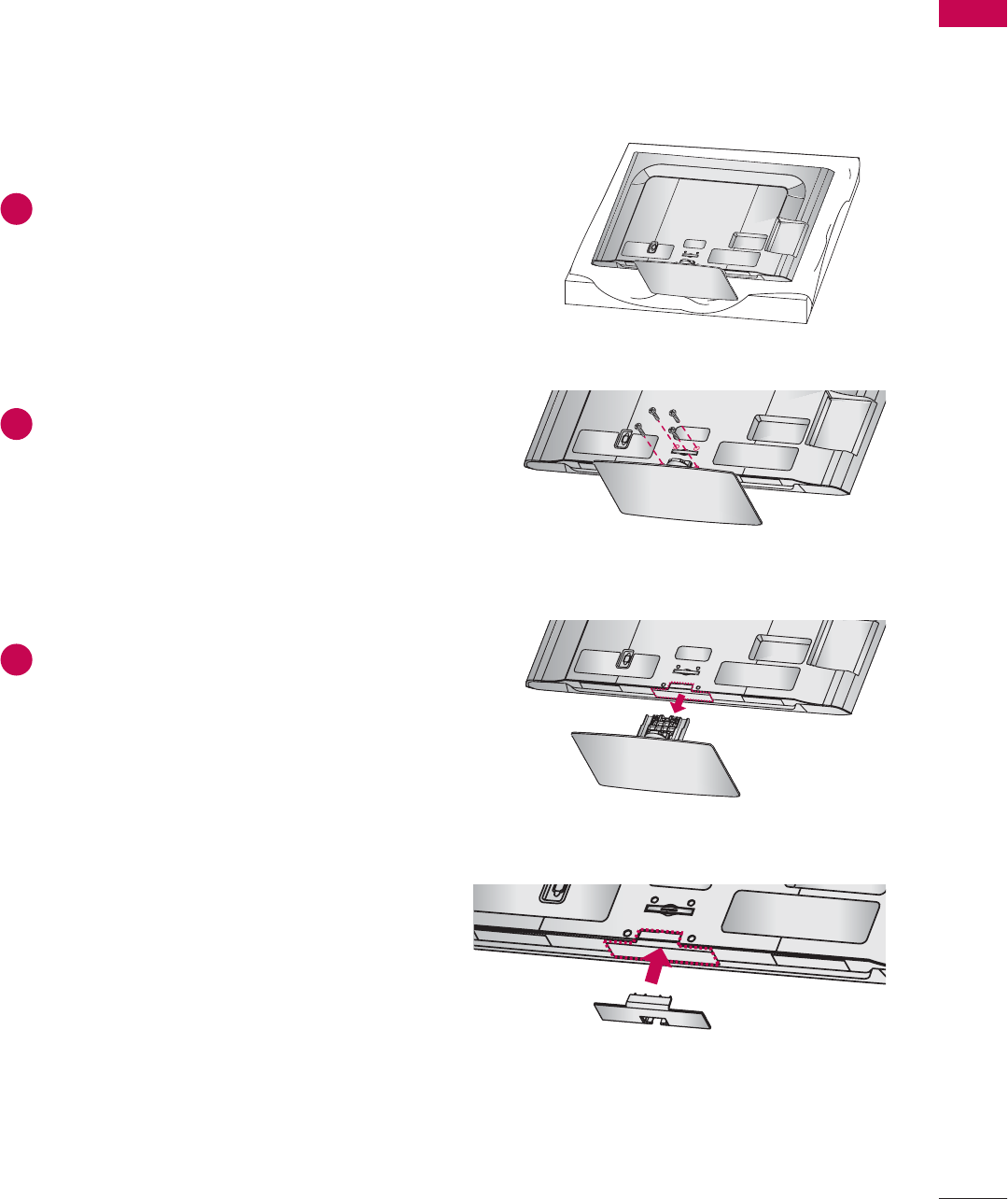
DETACHMENT
PROTECTION COVER
After removing the stand, install the included
PROTECTION COVER over the hole for the
stand.
Press the PROTECTION COVER into the TV until
you hear it click.
When installing the wall mounting bracket, use
the PROTECTION COVER.
1Carefully place the TV screen side down on
a cushioned surface to protect the screen
from damage.
2Remove the screws that hold the stand on.
3Detach the stand from TV.
PROTECTION COVER
Fix a guide to the outside.
(50PK750, 60PZ540,
60PZ550, 50/60PZ750)
(50PZ540/550)
(60PK750)
M4 x 30
M4 x 28
M4 x 26
PREPARATION
PREPARATION
22
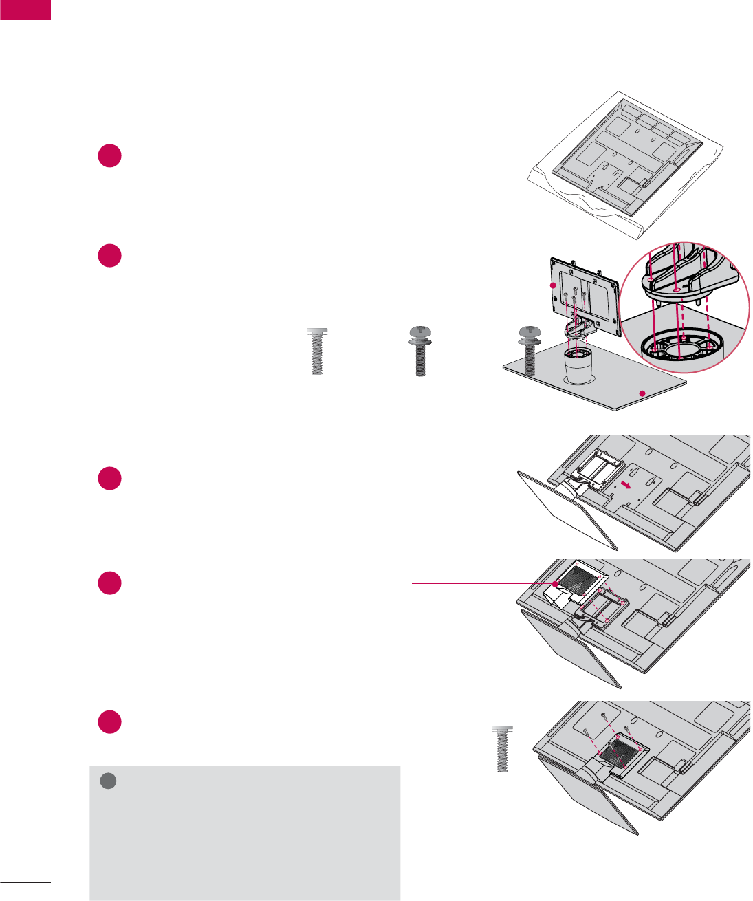
STAND INSTRUCTIONS
(For 32/42/46/52/60LD550, 47/55LD650)
ᯫ
Image shown may differ from your TV.
!
NOTE
ŹWhen assembling the desk type stand,
make sure the screws are fully tightened (If
not tightened fully, the TV can tilt forward
after the product installation). Do not over
tighten.
1Carefully place the TV screen side down on
a cushioned surface to protect the screen
from damage.
2Assemble the parts of the STAND BODY
with the STAND BASE of the TV.
3Assemble the TV as shown.
4Install the 4 screws into the holes shown.
AC IN
CABLEMANAGEMENT
AC IN
CABLE MANAGEMENT
AC IN
CABLE MANAGEMENT
STAND BASE
STAND BODY
INSTALLATION
M4 x 20
M4 x 20
23
PREPARATION
AC IN
CABLE MANAGEMENT
AC IN
CABLE MANAGEMENT
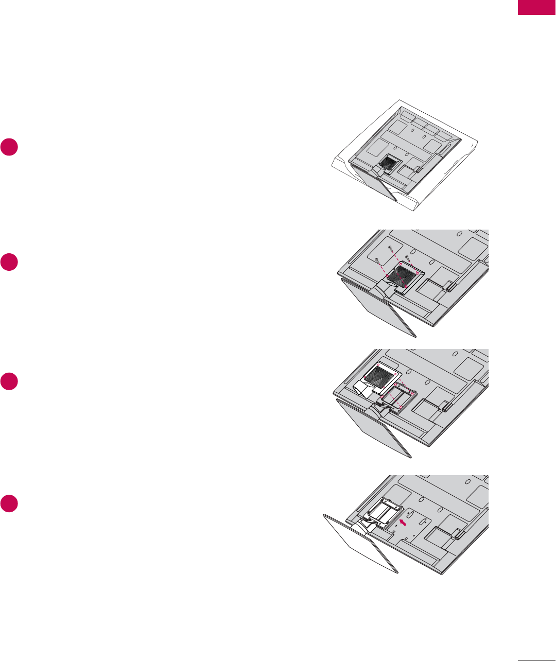
DETACHMENT
ACIN
CABLE MANAGEMENT
PROTECTION COVER
After removing the stand, install the included
PROTECTION COVER over the hole for the
stand.
Press the PROTECTION COVER into the TV until
you hear it click.
When installing the wall mounting bracket, use
the PROTECTION COVER.
1Carefully place the TV screen side down on
a cushioned surface to protect the screen
from damage.
2Remove the screws that hold the stand on.
3Detach the stand from TV.
PREPARATION
PREPARATION
24
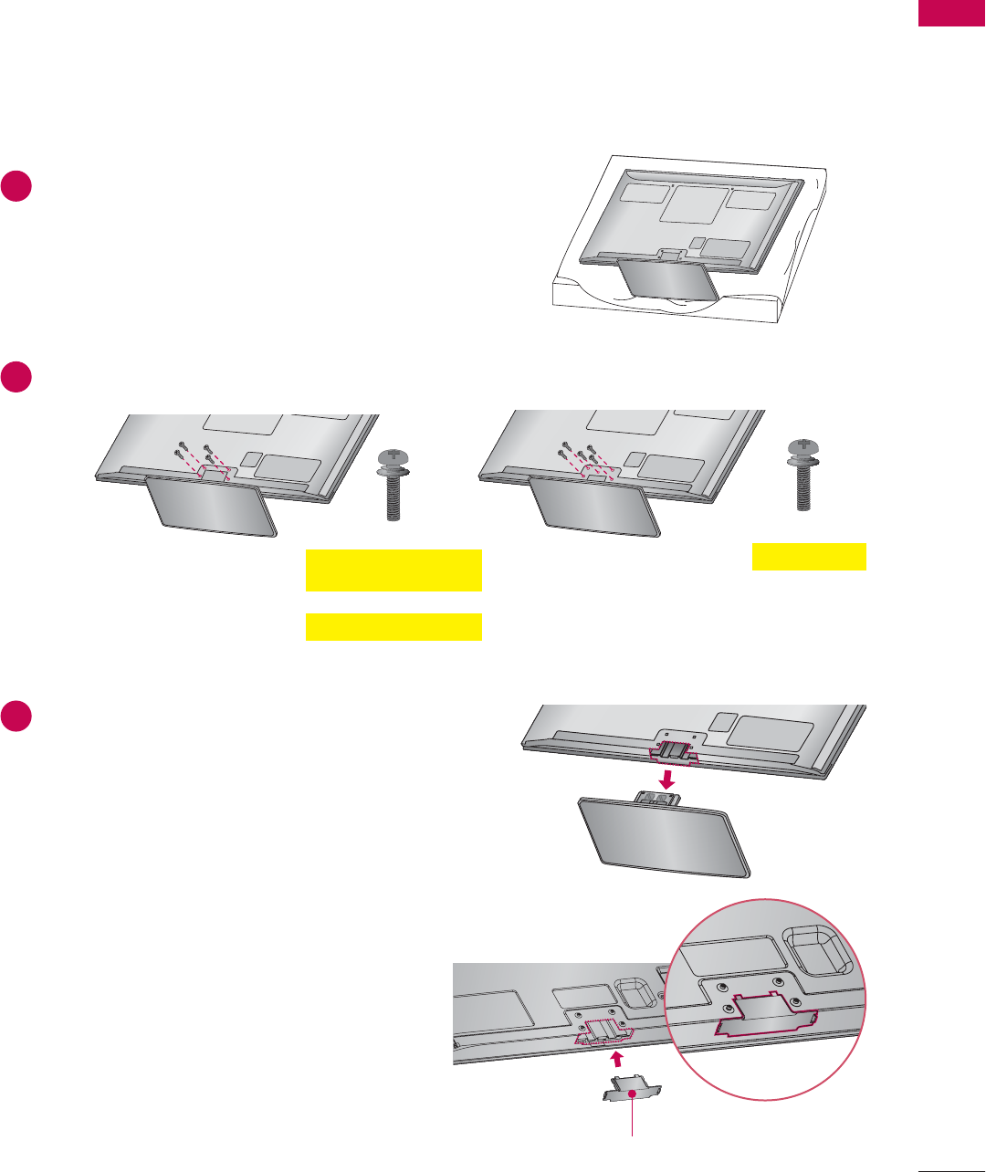
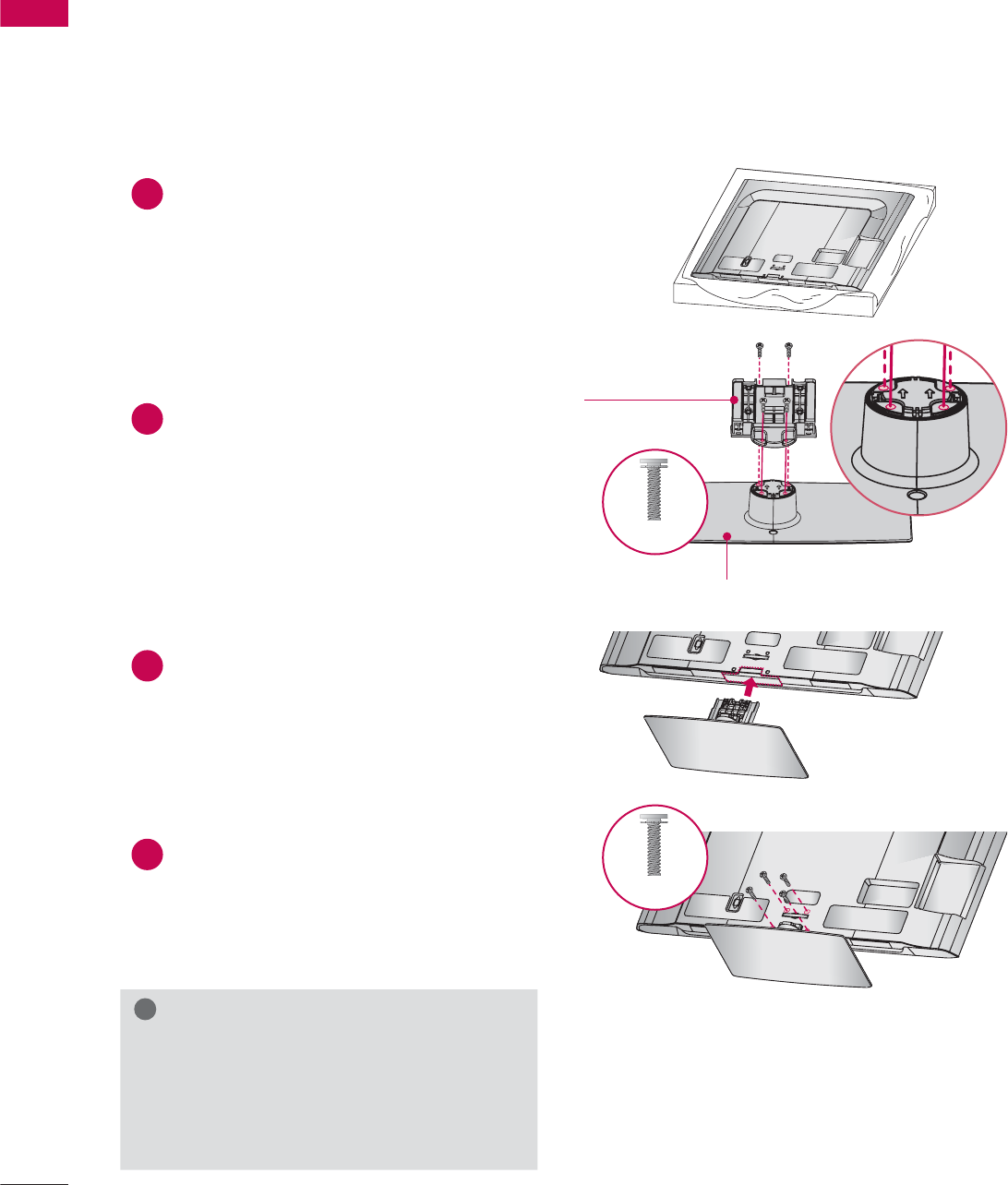
STAND INSTRUCTIONS
(For 42/47LE5350, 32/42/47/55LE5400, 42/47/55LE5500, 42/47/55LE7500, 47/55LE8500,
42/47/55LX6500)
ᯫ
Image shown may differ from your TV.
INSTALLATION
!
NOTE
ŹWhen assembling the desk type stand,
make sure the screws are fully tightened (If
not tightened fully, the TV can tilt forward
after the product installation). Do not over
tighten.
2Assemble the parts of the STAND BODY
with the STAND BASE of the TV.
At this time, tighten the screws that hold the
STAND BODY on.
3Assemble the TV as shown.
1Carefully place the TV screen side down on
a cushioned surface to protect the screen
from damage.
4Assemble the part of the STAND
REAR COVER with the TV.
5Install the 4 screws into the holes shown.
STAND BASE
STAND BODY
STAND REAR
COVER
M4 x 20
(47/55LE8500)
M4 x 16
(Other models)
M4 x 24 M4 x 26
(55LE5400/5500/7500,
55LX6500, 42LE5350)
(47LE5350)
M4 x 20
(47/55LE8500)
M4 x 16
(Other models)
25
PREPARATION
DETACHMENT
1Carefully place the TV screen side down on
a cushioned surface to protect the screen
from damage.
2Remove the screws that hold the stand on.
3Detach the STAND REAR COVER from TV.
4Detach the stand from TV.
PREPARATION
PREPARATION
26
VESA WALL MOUNTING
Install your wall mount on a solid wall perpendicular to the floor. When attaching to other building mate-
rials, please contact your nearest installer.
If installed on a ceiling or slanted wall, it may fall and result in severe personal injury.
We recommend that you use an LG brand wall mount when mounting the TV to a wall.
LG recommends that wall mounting be performed by a qualified professional installer.
Model
VESA (A * B)
A
B
Standard
Screw Quantity Wall Mounting Bracket
(sold separately)
32LD550,
32LE5400 200 * 100 M4 4 LSW100B, LSW100BG
42/46LD550,
47LD650,
42/47LE5350,
42/47LE5400,
42/47LE5500,
42/47LE7500,
47LE8500,
42/47LX6500
200 * 200 M6 4 LSW200B, LSW200BG
52LD550, 55LD650,
55LE5400,
55LE5500,
55LE7500,
55LE8500,
60LD550,
55LX6500
400 * 400 M6 4 LSW400B, LSW400BG,
DSW400BG
50PK750,
50PZ540
50PZ550,
50PZ750
400 * 400 M6 4 PSW400B, PSW400BG
60PK750,
60PZ540
60PZ550,
60PZ750
600 * 400 M8 4 PSW600B, PSW600BG

27
PREPARATION
CAUTION
ŹDo not install your wall mount kit while your TV is turned on. It may result in personal injury due to
electric shock.
!
NOTE
ŹScrew length needed depends on the wall
mount used. For further information, refer to
the instructions included with the mount.
ŹStandard dimensions for wall mount kits are
shown in the table.
ŹWhen purchasing our wall mount kit, a detailed
installation manual and all parts necessary for
assembly are provided.
ŹDo not use screws longer than the standard
dimension, as they may cause damage to the
inside to the TV.
ŹFor wall mounts that do not comply with the
VESA standard screw specifications, the length
of the screws may differ depending on their
specifications.
ŹDo not use screws that do not comply with the
VESA standard screw specifications.
Do not use fasten the screws too strongly, this
may damage the TV or cause the TV to a fall,
leading to personal injury. LG is not liable for
these kinds of accidents.
ŹLG is not liable for TV damage or personal
injury when a non-VESA or non specified wall
mount is used or the consumer fails to follow
the TV installation instructions.
PREPARATION
PREPARATION
28
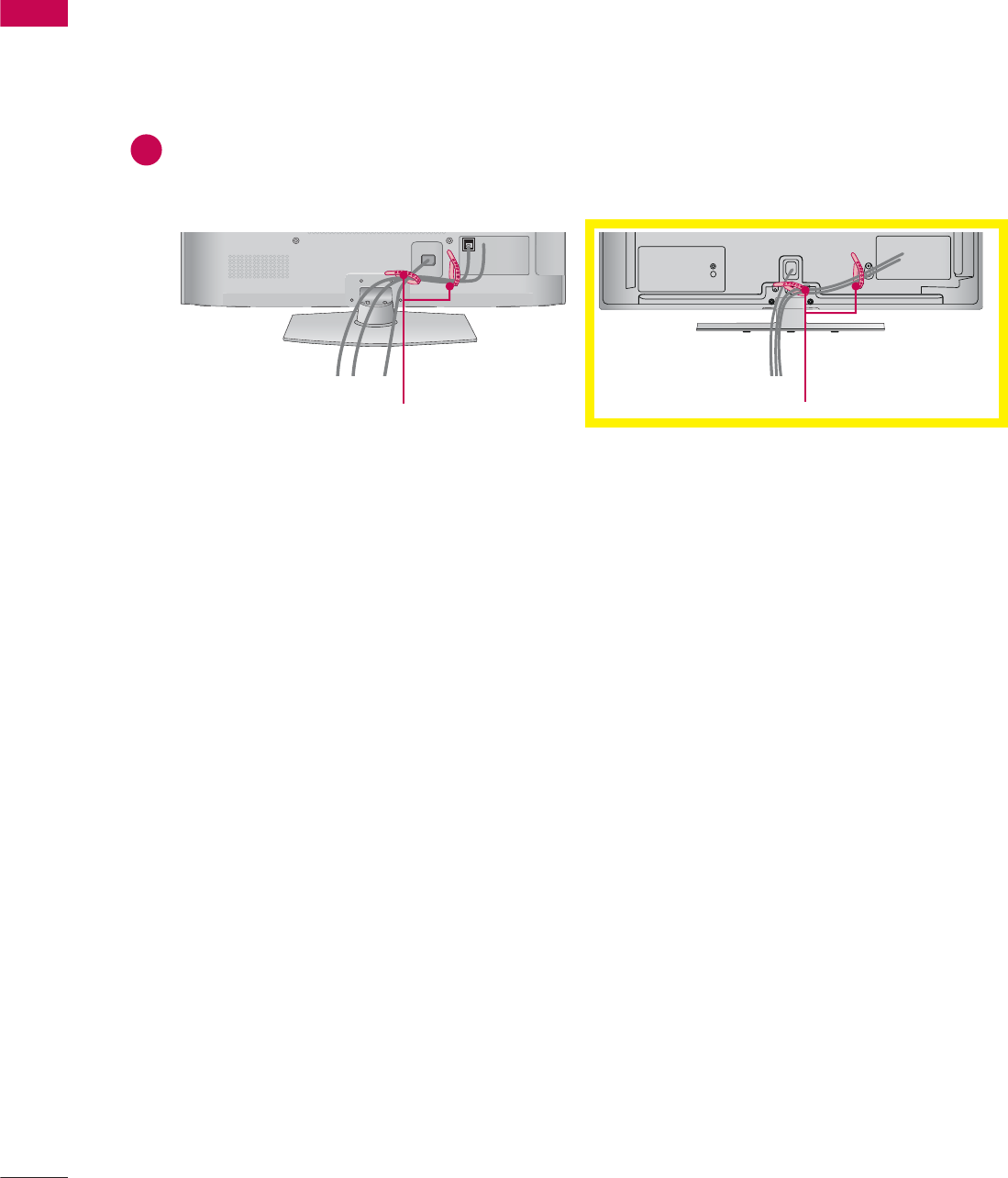
CABLE MANAGEMENT
ᯫ
Image shown may differ from your TV.
Plasma TV
CABLE HOLDER CABLE HOLDER
1After connecting the cables as necessary, install the CABLE HOLDER as shown and bundle the
cables.
In case of the LAN cable, install as shown to reduce the electromagnetic wave.
29
PREPARATION
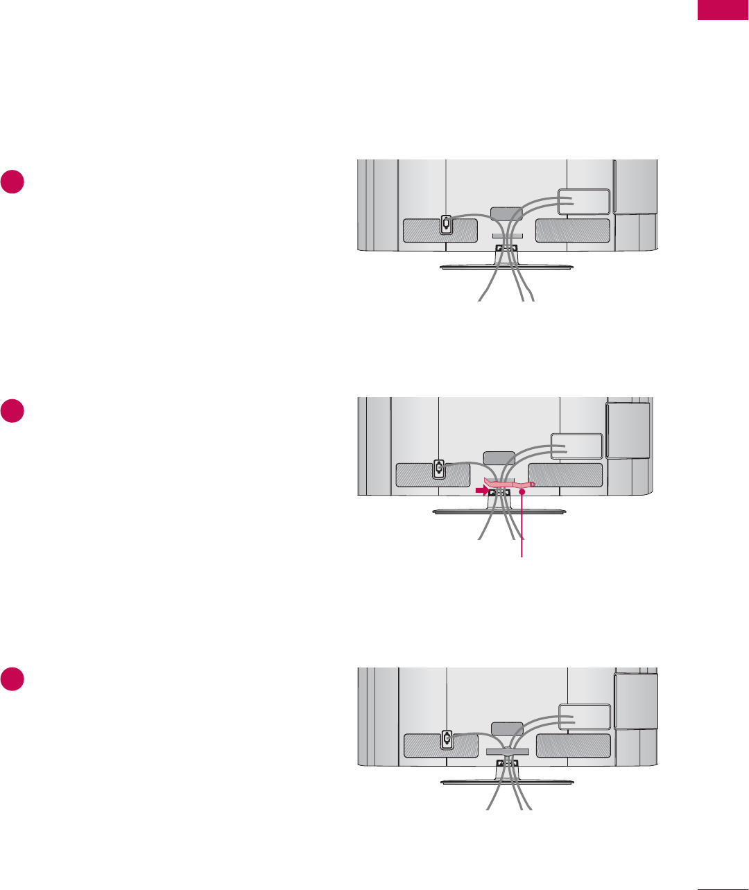
32/42/46/52/60LD550, 47/55LD650
ᯫ
Image shown may differ from your TV.
1Connect the cables as necessary.
To connect additional equipment, see the
EXTERNAL EQUIPMENT SETUP section.
2Open the CABLE MANAGEMENT CLIP as
shown.
3Put the cables inside the CABLE
MANAGEMENT CLIP and snap it closed.
AC IN
AC IN
AC IN
CABLE MANAGEMENT CLIP
PREPARATION
PREPARATION
30
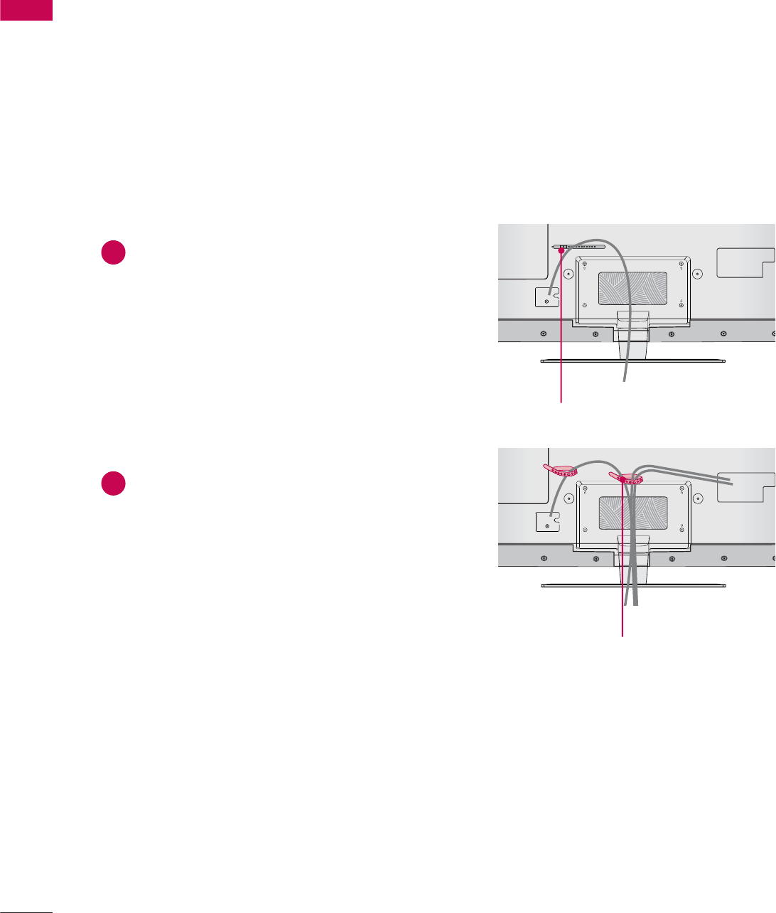
CABLE HOLDER
CABLE HOLDER
ᯫ
Image shown may differ from your TV.
2After connecting the cables as necessary,
install the CABLE HOLDER as shown
and bundle the cables.
1Secure the power cord with the CABLE
HOLDER on the TV back cover.
It will help prevent the power cable from
being removed by accident.
42/47LE5350, 32/42/47/55LE5400, 42/47/55LE5500, 42/47/55LE7500, 47/55LE8500,
42/47/55LX6500
31
PREPARATION
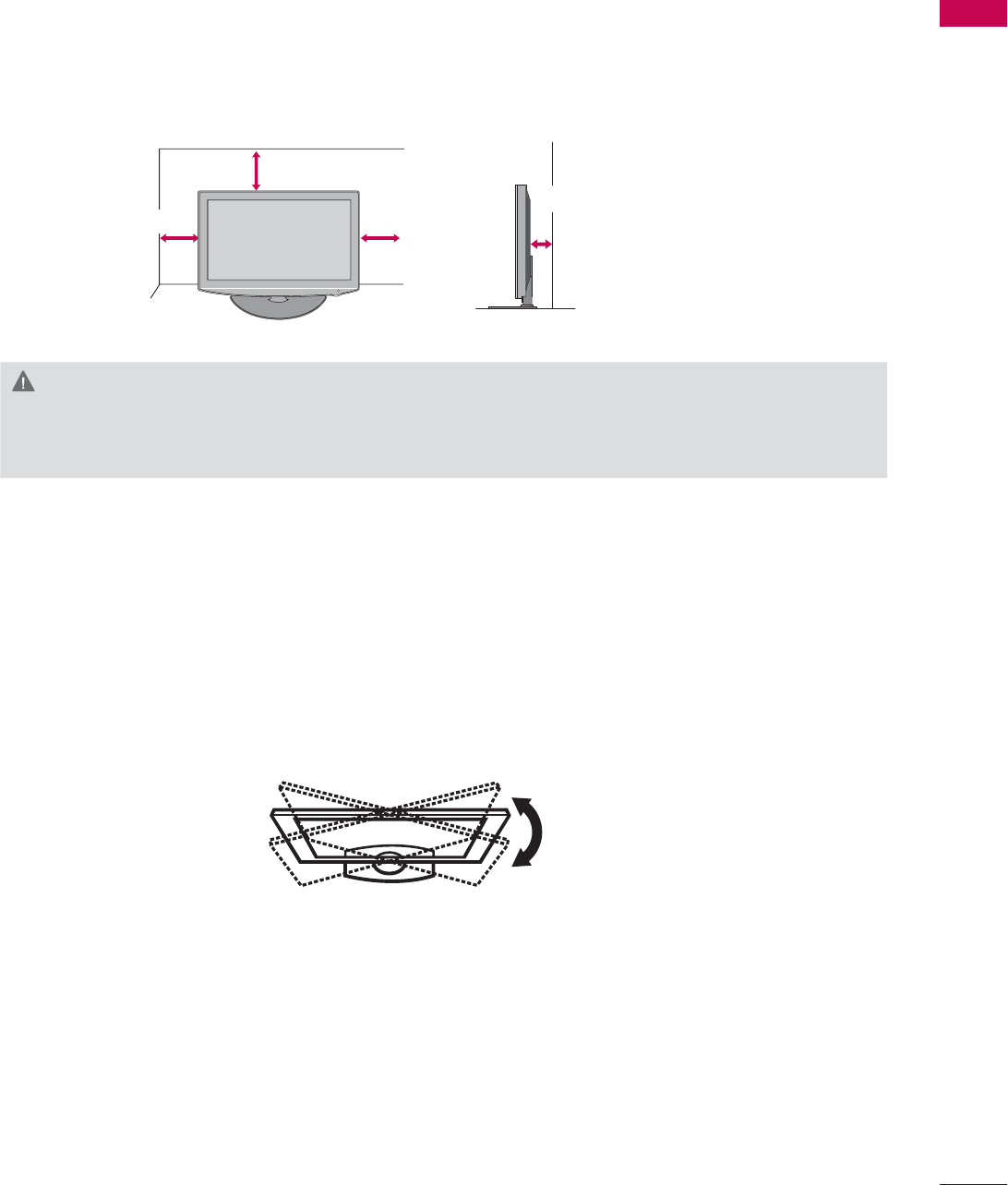
DESKTOP PEDESTAL INSTALLATION
SWIVEL STAND
After installing the TV, you can adjust the TV set manually to the left or right direction by 20 º to suit
your viewing position.
ᯫ
Image shown may differ from your TV.
For proper ventilation, allow a clearance of 10.1 cm (4 inch) on all four sides from the wall.
10.1 cm (4 inch)
10.1 cm (4 inch)
10.1 cm (4 inch)
10.1 cm (4 inch)
CAUTION
ŹEnsure adequate ventilation by following the clearance recommendations.
ŹDo not mount near or above any type of heat source.
PREPARATION
PREPARATION
32
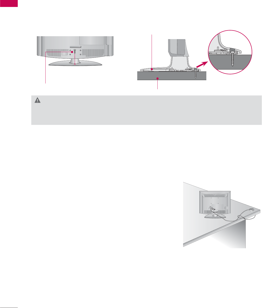
ATTACHING THE TV TO A DESK (For
32/42LD550, 32LE5400
)
The TV must be attached to a desk so it cannot be pulled in a forward/backward direction, poten-
tially causing injury or damaging the product.
1-Screw
(provided as parts of the product)
Desk
Stand
KENSINGTON SECURITY SYSTEM
ᯫ
This feature is not available for all models.
- The TV is equipped with a Kensington Security System con-
nector on the back panel. Connect the Kensington Security
System cable as shown below.
- For the detailed installation and use of the Kensington Security
System, refer to the user’s guide provided with the Kensington
Security System.
For further information, contact http://www.kensington.com,
the internet homepage of the Kensington company. Kensington
sells security systems for expensive electronic equipment such
as notebook PCs and LCD projectors.
NOTE: The Kensington Security System is an optional accessory.
WARNING
ŹTo prevent TV from falling over, the TV should be securely attached to the floor/wall per installa-
tion instructions. Tipping, shaking, or rocking the machine may cause injury.
ᯫ
Image shown may differ from your TV.
33
PREPARATION
SECURING THE TV TO THE WALL TO PREVENT FALLING
WHEN THE TV IS USED ON A STAND
We recommend that you set up the TV close to a wall so it cannot fall over if pushed backwards.
Additionally, we recommend that the TV be attached to a wall so it cannot be pulled in a forward
direction, potentially causing injury or damaging the product.
Caution: Please make sure that children don’t climb on or hang from the TV.
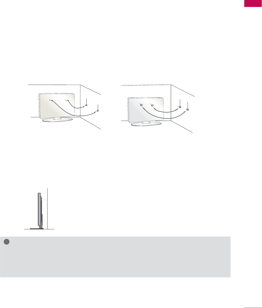
ᯫ
Insert the eye-bolts (or TV brackets and bolts) to tighten the product to the wall as shown in the
picture.
* If your product has the bolts in the eye-bolts position before inserting the eye-bolts, loosen the
bolts.
* Insert the eye-bolts or TV brackets/bolts and tighten them securely in the upper holes.
Secure the wall brackets with the bolts (sold separately) to the wall. Match the height of the bracket
that is mounted on the wall to the holes in the product.
Ensure the eye-bolts or brackets are tightened securely.
ᯫ
Use a sturdy rope (sold separately) to tie the product. It is safer to tie the
rope so it becomes horizontal between the wall and the product.
ᯫ
You should purchase necessary components to prevent the TV from tipping over (when not using a
wall mount).
ᯫ
Image shown may differ from your TV.
!
NOTE
ŹUse a platform or cabinet strong enough and large enough to support the size and weight of
the TV.
ŹTo use the TV safely make sure that the height of the bracket on the wall and the one on the TV are
the same.
PREPARATION
PREPARATION
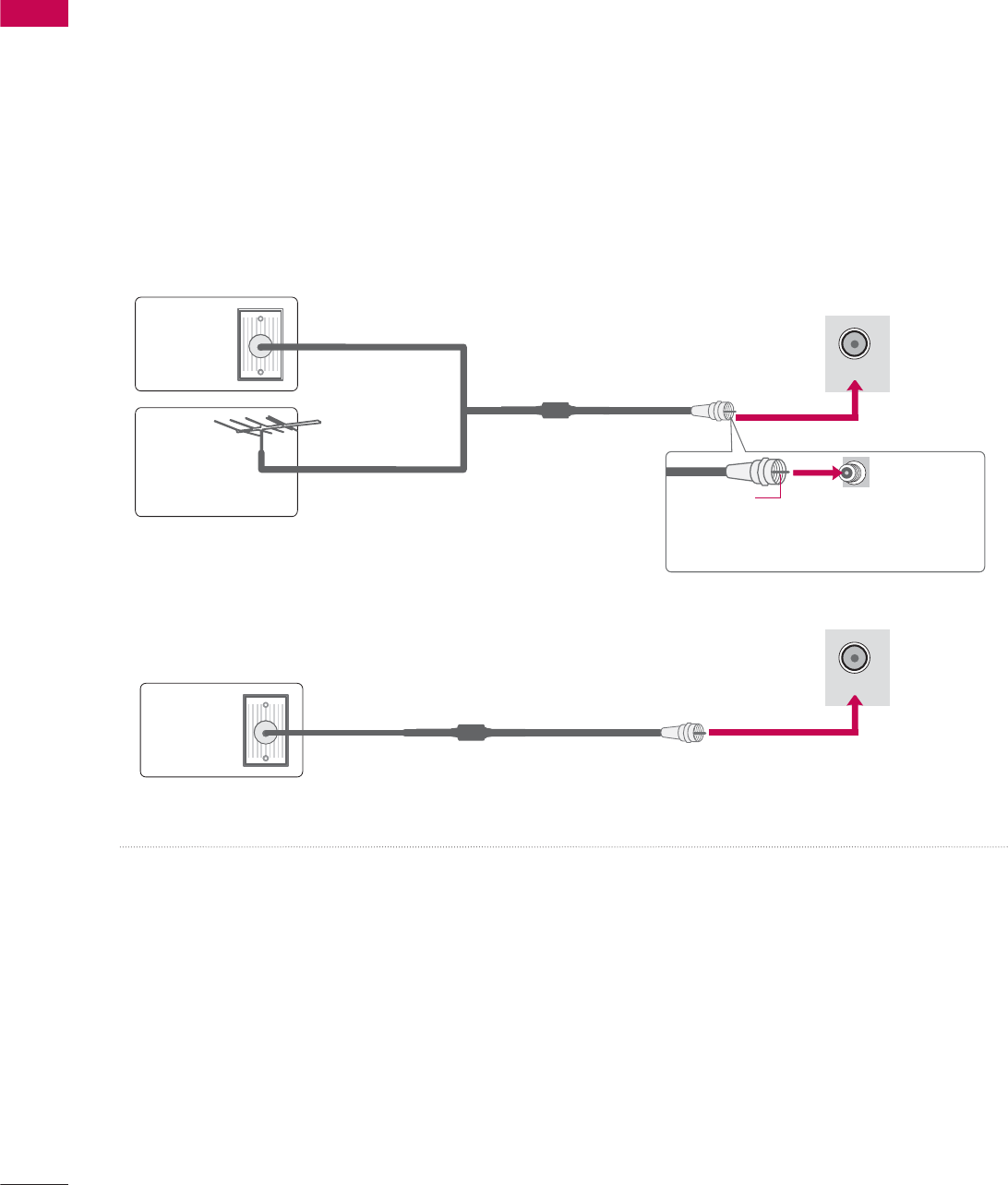
34
ANTENNA OR CABLE CONNECTION
ᯫ
To prevent damage do not connect to the power outlet until all connections are made between the
devices.
ᯫ
Image shown may differ from your TV.
1. Antenna (Analog or Digital)
Wall Antenna Socket or Outdoor Antenna without a Cable Box Connections.
For optimum picture quality, adjust antenna direction if needed.
2. Cable
Wall
Antenna
Socket
Outdoor
Antenna
(VHF, UHF)
Cable TV
Wall Jack
Multi-family Dwellings/Apartments
(Connect to wall antenna socket)
RF Coaxial Wire (75 Ω)
RF Coaxial Wire (75 Ω)
Single-family Dwellings /Houses
(Connect to wall jack for outdoor antenna)
Be careful not to bend the copper wire
when connecting the antenna.
Copper Wire
ᯫ
If the antenna needs to be split for two TV’s, install a 2-Way Signal Splitter.
ᯫ
For much more information about antennas visit our Knowledgebase at http://lgknowledgebase.
com. Search for antenna.
ANTENNA/
CABLE IN
ANTENNA/
CABLE IN
35
EXTERNAL EQUIPMENT SETUP
HD RECEIVER SETUP
ᯫ
To prevent the equipment damage, never plug in any power cords until you have finished connecting all
equipment.
ᯫ
I
mage shown may differ from your TV.
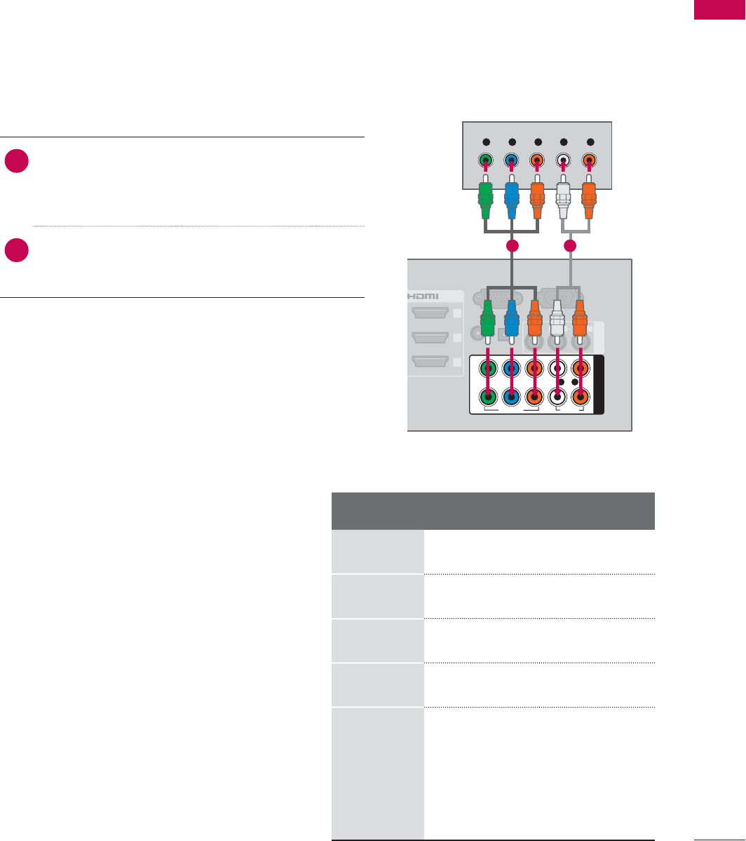
1. How to connect
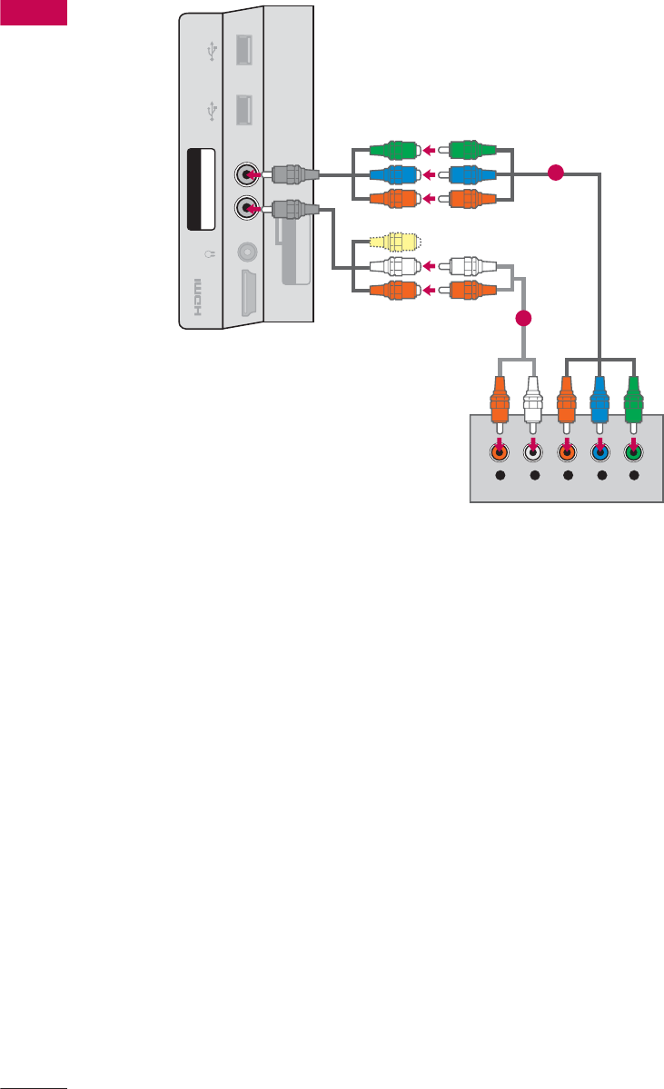
1Connect the video outputs (Y, P B, PR) of the
digital set-top box to the COMPONENT IN
VIDEO 1, 2,or3* jacks on the TV. Match the
jack colors (Y = green, PB = blue, and PR = red).
2Connect the audio output of the digital set-top
box to the COMPONENT IN AUDIO 1, 2,or3*
jacks on the TV.
2. How to use
ᯫ
Turn on the digital set-top box.
(Refer to the owner’s manual for the digital set-
top box operation.)
ᯫ
Select the Component1,Component2, or
Component3 input source on the TV using the
INPUT button on the remote control.
Component Connection
This TV can receive digital over-the-air/digital cable signals without an external digital set-top box.
However, if you do receive digital signals from a digital set-top box or other digital external device.
EXTERNAL EQUIPMENT SETUP
RGB IN (PC)
(RGB/DVI)
RS-232C IN
(
SERVICE ONLY)
OPTICAL
DIGITAL
/DVI IN
2
3
1
VIDEO
AUDIO
L(MONO)
R
AV IN 1
AUDIO IN
AUDIO OUT
VIDEO AUDIO
COMPONENT IN
YP
B
P
R
L R
2
1
Y L RP
B
P
R
1 2
Y, C B/PB, CR/PR
Resolution Horizontal
Frequency(kHz)Vertical
Frequency(Hz)
720x480i 15.73 59.94
15.73 60.00
720x480p 31.47 59.94
31.50 60.00
1280x720p 44.96 59.94
45.00 60.00
1920x1080i
33.72 59.94
33.75 60.00
1920x1080p
26.97 23.976
27.00 24.00
33.71 29.97
33.75 30.00
67.432 59.94
67.50 60.00
* Component3: For LED LCD TV
EXTERNAL EQUIPMENT SETUP
EXTERNAL EQUIPMENT SETUP
36
YLR P
B
P
R
AUDIO / Y P
B
P
R
IN 4
H/P USB IN 1 USB IN 2
AV IN2
VIDEO / AUDIO
COMPONENT IN3
For LED LCD TV
1
2
37
EXTERNAL EQUIPMENT SETUP
HDMI Connection
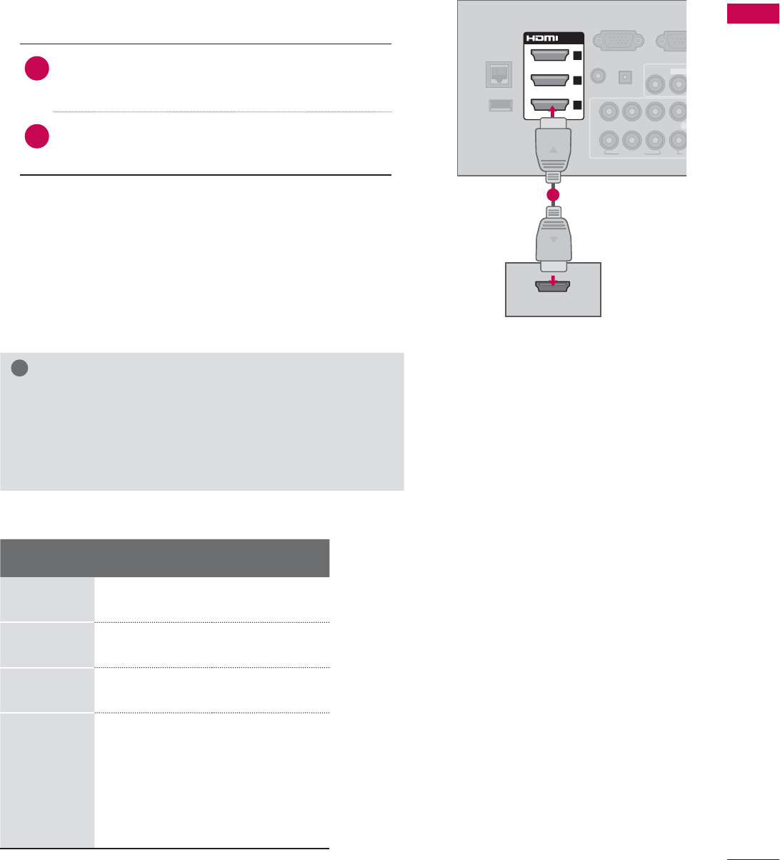
1. How to connect
1Connect the digital set-top box to HDMI/DVI IN
1,2,3, or 4jack on the TV.
2No separate audio connection is necessary.
HDMI supports both audio and video.
2. How to use
ᯫ
Turn on the digital set-top box.
(Refer to the owner’s manual for the digital set-
top box.)
ᯫ
Select the HDMI1,HDMI2,HDMI3, or HDMI4 input
source on the TV using the INPUT button on the
remote control.
!
NOTE
ŹIf an HDMI cable doesn’t support High Speed HDMI,
it can cause flickers or no screen display. In this case
use the latest cables that support High Speed HDMI.
ŹHDMI Audio Supported Format: Dolby Digital (32 kHz, 44.1
kHz, 48 kHz), Linear PCM (32 kHz, 44.1 kHz, 48 kHz)
HDMI-DTV
Resolution Horizontal
Frequency(kHz)Vertical
Frequency(Hz)
720x480p 31.47 59.94
31.50 60.00
1280x720p 44.96 59.94
45.00 60.00
1920x1080i
33.72 59.94
33.75 60.00
1920x1080p
26.97 23.976
27.00 24.00
33.71 29.97
33.75 30.00
67.432 59.94
67.50 60.00
HDMI OUTPUT
RGB IN (PC)
LAN
WIRELESS
CONTROL
(RGB/DVI)
VIDEO
L(MONO
VIDEO A
AUDIO IN
AUDIO OUT
2
1
/DVI IN
2
3
1
YP
B
P
R
L
OPTICAL DIGITAL
RS-23
2
(
SERVICE
ꔡ
1
EXTERNAL EQUIPMENT SETUP
EXTERNAL EQUIPMENT SETUP
38
DVI to HDMI Connection
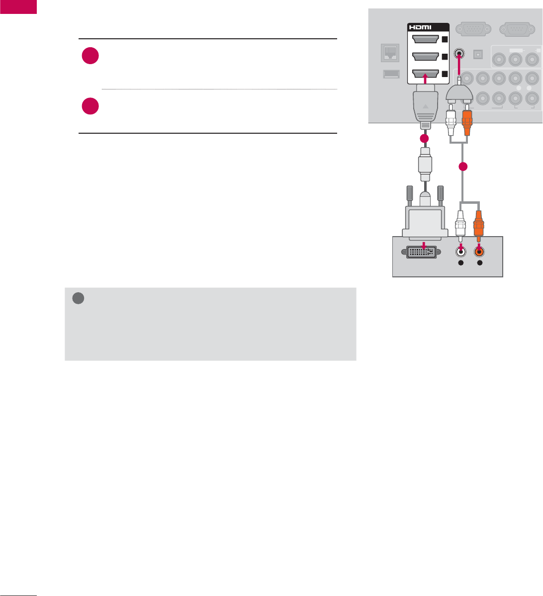
1. How to connect
1Connect the DVI output of the digital set-top
box to the HDMI/DVI IN 1,2,3, or 4* jack on
the TV.
2Connect the digital set-top box audio output to
the AUDIO IN (RGB/DVI) jack on the TV.
2. How to use
ᯫ
Turn on the digital set-top box.
(Refer to the owner’s manual for the digital set-
top box.)
ᯫ
Select the HDMI1,HDMI2,HDMI3, or HDMI4* input
source on the TV using the INPUT button on the
remote control.
!
NOTE
ŹA DVI to HDMI cable or adapter is required for this con-
nection. DVI doesn't support audio, so a separate audio
connection is necessary.
L R
DVI OUTPUT
AUDIO
RGB IN (PC)
LAN
WIRELESS
CONTROL
RS-232C IN
(
SERVICE ONLY)
VIDEO
AUDIO
L(MONO)
R
VIDEO AUDIO
YP
B
P
R
L R
AUDIO OUT
2
1
/DVI IN
2
3
1
(RGB/DVI)
AUDIO IN
OPTICAL DIGITAL
ꔡ
1
2
* HDMI4: For Plasma TV
39
EXTERNAL EQUIPMENT SETUP
DVD SETUP
Component Input ports
To get better picture quality, connect a DVD player
to the component input ports as shown below.
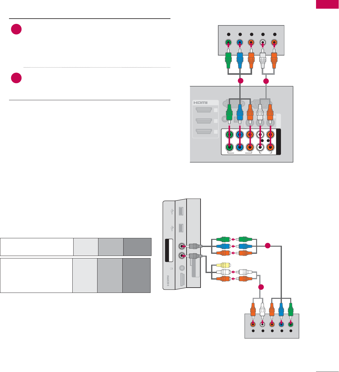
1. How to connect
1Connect the video outputs (Y, P B, PR) of the
DVD to the COMPONENT IN VIDEO 1, 2,or3*
jacks on the TV.
Match the jack colors (Y = green, PB = blue, and
PR = red).
2Connect the audio outputs of the DVD to the
COMPONENT IN AUDIO 1, 2,or3* jacks on the
TV.
2. How to use
ᯫ
Turn on the DVD player, insert a DVD.
ᯫ
Select the Component1, Component2, or
Component3 input source on the TV using the
INPUT button on the remote control.
ᯫ
Refer to the DVD player’s manual for operating
instructions.
Component Connection
RGB IN (PC)
S
L
(RGB/DVI)
/DVI IN
2
3
1
VIDEO
AUDIO
L(MONO)
R
AV IN 1
AUDIO IN
AUDIO OUT
VIDEO AUDIO
COMPONENT IN
YP
B
P
R
L R
2
1
Y L RP
B
P
R
OPTICAL DIGITAL
RS-232C IN
(
SERVICE ONLY)
12
* Component3: For LED LCD TV
Component ports on
the TV
YP
B
P
R
Video output ports
on DVD player
YP
B
P
R
YB-YR-Y
YCbCr
YPb Pr
YLR P
B
P
R
AUDIO / Y P
B
P
R
IN 4
H/P USB IN 1 USB IN 2
AV IN2
VIDEO / AUDIO
COMPONENT IN3
1
2
For LED LCD TV
EXTERNAL EQUIPMENT SETUP
EXTERNAL EQUIPMENT SETUP
40
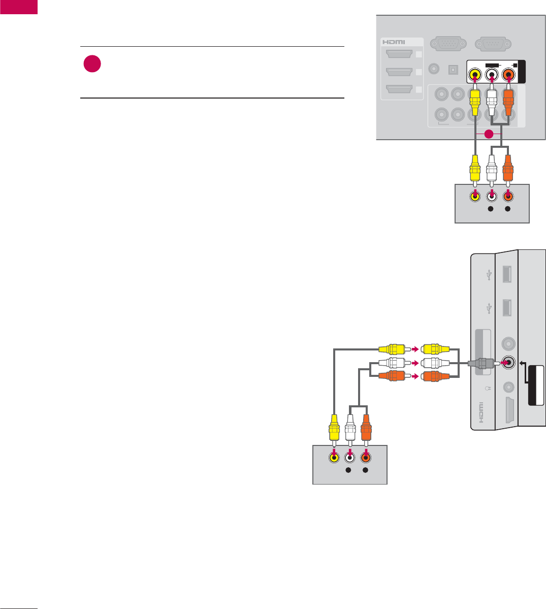
Composite (RCA) Connection
1. How to connect
1Connect the AUDIO/VIDEO jacks between TV
and DVD. Match the jack colors (Video = yellow,
Audio Left = white, and Audio Right = red)
2. How to use
ᯫ
Turn on the DVD player, insert a DVD.
ᯫ
Select the AV1 or AV2 input source on the TV
using the INPUT button on the remote control.
ᯫ
Refer to the DVD player's manual for operating
instructions.
RGB IN (PC)
S
L
(RGB/DVI)
/DVI IN
2
3
1
VIDEO AUDIO
COMPONENT IN
AUDIO IN
AUDIO OUT
2
1
VIDEO
AUDIO
L(MONO)
R
AV IN 1
YP
B
P
R
L R
OPTICAL DIGITAL
RS-232C IN
(
SERVICE ONLY)
L R
VIDEO
AUDIO
1
L R
VIDEO
AUDIO
AUDIO / Y P
B
P
R
IN 4
H/P USB IN 1 USB IN 2
VIDEO / AUDIO
COMPONENT IN3
AV IN2
For LED LCD TV
41
EXTERNAL EQUIPMENT SETUP
HDMI OUTPUT
RGB IN (PC)
LAN
WIRELESS
CONTROL
(RGB/DVI)
VIDEO
AUDIO
L(MONO)
R
VIDEO AUDIO
COMPONENT INAV IN 1
AUDIO IN
AUDIO OUT
2
1
/DVI IN
2
3
1
YP
B
P
R
L R
OPTICAL DIGITAL
RS-232C IN
(
SERVICE ONLY)
ꔡ
1
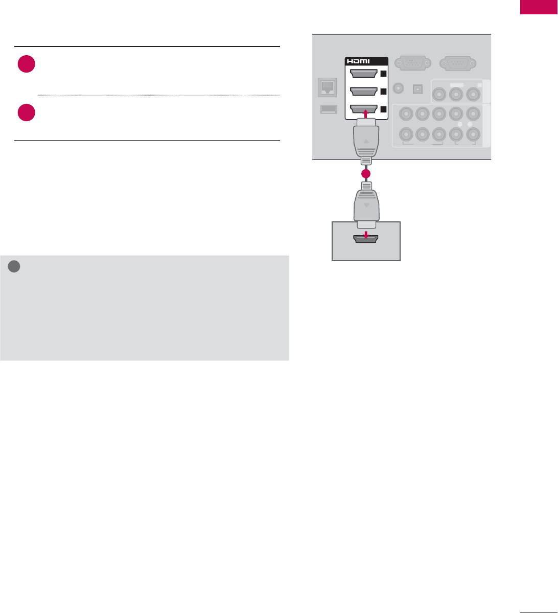
HDMI Connection
1. How to connect
1Connect the HDMI output of the DVD to the
HDMI/DVI IN 1,2,3or 4 jack on the TV.
2No separate audio connection is necessary.
HDMI supports both audio and video.
2. How to use
ᯫ
Select the HDMI1,HDMI2,HDMI3, or HDMI4 input
source on the TV using the INPUT button on the
remote control.
ᯫ
Refer to the DVD player's manual for operating
instructions.
!
NOTE
ŹIf an HDMI cable doesn’t support High Speed HDMI,
it can cause flickers or no screen display. In this case
use the latest cables that support High Speed HDMI.
ŹHDMI Audio Supported Format: Dolby Digital (32 kHz, 44.1
kHz, 48 kHz), Linear PCM (32 kHz, 44.1 kHz, 48 kHz)
EXTERNAL EQUIPMENT SETUP
EXTERNAL EQUIPMENT SETUP
42
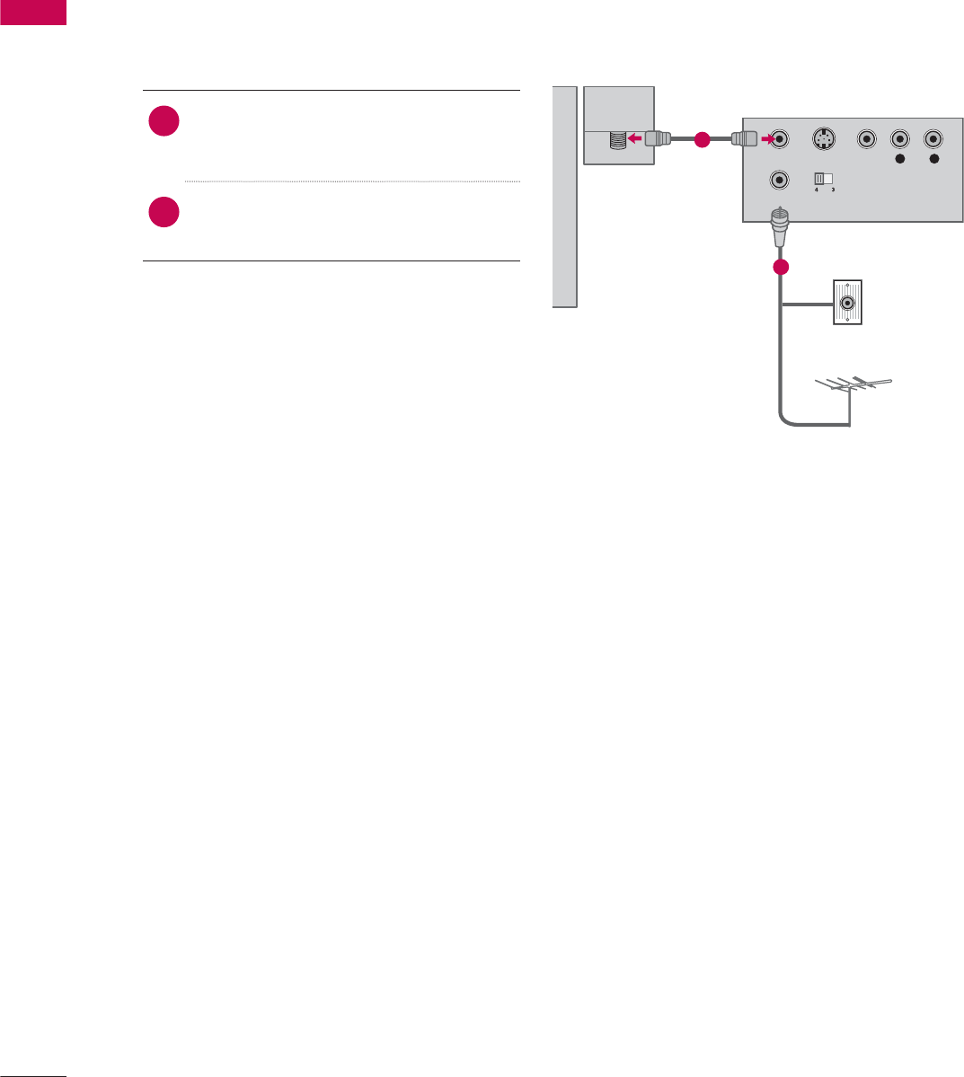
VCR SETUP
Antenna Connection
ANTENNA/
CABLE IN
L R
S-VIDEO VIDEO
AUDIO
OUTPUT
SWITCH
ANT IN
ANT OUT
Wall Jack
Antenna
1. How to connect
1Connect the RF antenna out socket
of the VCR to the ANTENNA/CABLE
IN socket on the TV.
2Connect the antenna cable to the RF
antenna in socket of the VCR.
2. How to use
ᯫ
Set VCR output switch to 3 or 4 and
then tune TV to the same channel num-
ber.
ᯫ
Insert a video tape into the VCR and
press PLAY on the VCR (Refer to the
VCR owner’s manual).
1
2
43
EXTERNAL EQUIPMENT SETUP
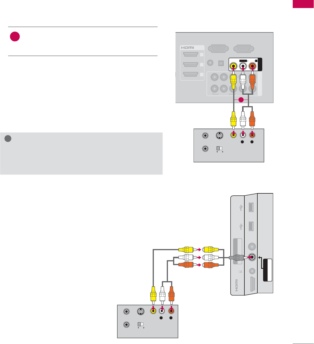
Composite (RCA) Connection
S-VIDEO
OUTPUT
SWITCH
ANT IN
ANT OUT
RGB IN (PC)
S
S
O
L
(RGB/DVI)
/DVI IN
2
3
1
VIDEO AUDIO
COMPONENT IN
AUDIO IN
AUDIO OUT
2
1
VIDEO
AUDIO
L(MONO)
R
AV IN 1
YP
B
P
R
L R
OPTICAL DIGITAL
RS-232C IN
(
SERVICE ONLY)
L R
VIDEO
AUDIO
1. How to connect
1Connect the AUDIO/VIDEO jacks between TV
and VCR. Match the jack colors (Video = yellow,
Audio Left = white, and Audio Right = red)
2. How to use
ᯫ
Insert a video tape into the VCR and press PLAY
on the VCR. (Refer to the VCR owner’s manual.)
ᯫ
Select the AV1 or AV2 input source on the TV
using the INPUT button on the remote control.
!
NOTE
ŹIf you have a mono VCR, connect the audio cable
from the VCR to the AUDIO L/MONO jack of the TV.
1
S-VIDEO
OUTPUT
SWITCH
ANT IN
ANT OUT
L R
VIDEO
AUDIO
AUDIO / Y P
B
P
R
IN 4
H/P USB IN 1 USB IN 2
VIDEO / AUDIO
COMPONENT IN3
AV IN2
For LED LCD TV
EXTERNAL EQUIPMENT SETUP
EXTERNAL EQUIPMENT SETUP
44
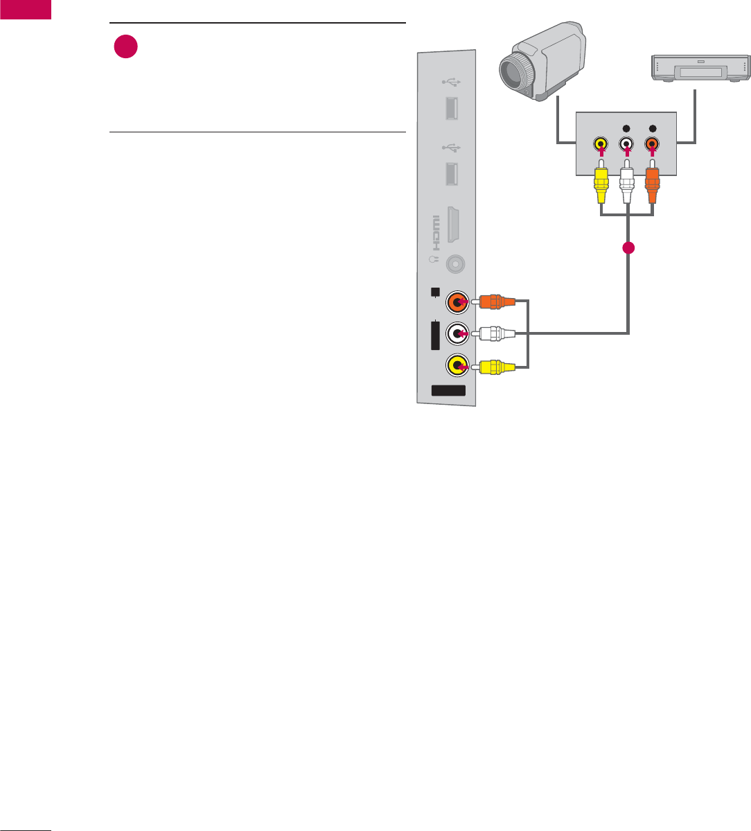
OTHER A/V SOURCE SETUP
AV IN 2
VIDEO
AUDIO
L(MONO)
R
H/P
IN 4
USB IN 1 USB IN 2
L R
VIDEO
Camcorder
Video Game Set
1. How to connect
1Connect the AUDIO/VIDEO jacks
between TV and external equipment.
Match the jack colors
.
(Video = yellow, Audio Left = white, and
Audio Right = red)
2. How to use
ᯫ
Select the AV1 or AV2 input source on
the TV using the INPUT button on the
remote control.
ᯫ
Operate the corresponding external
equipment.
1
45
EXTERNAL EQUIPMENT SETUP
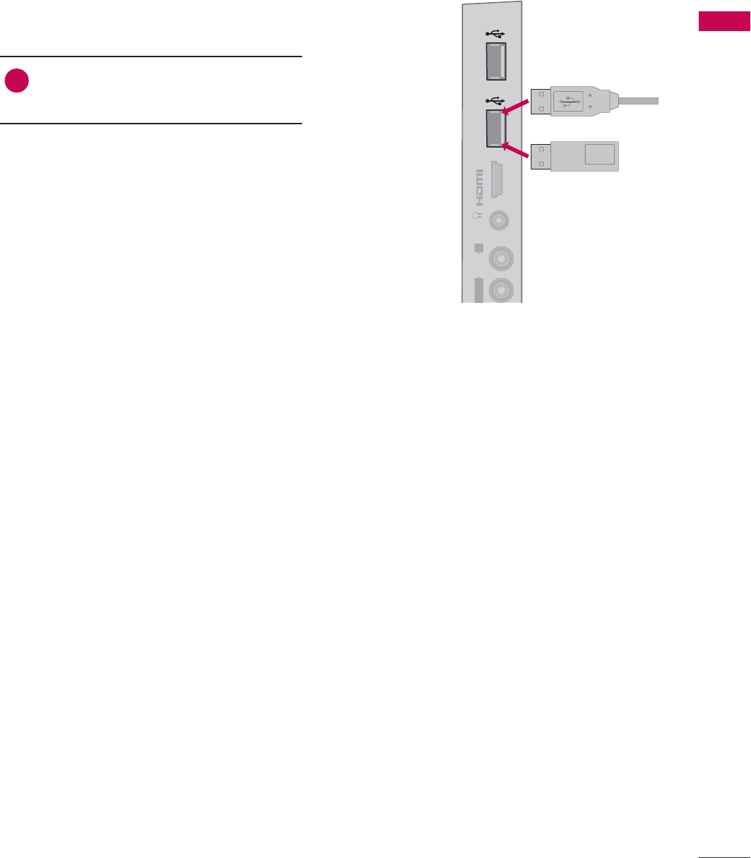
USB CONNECTION
IN 4
AUDIO
L
(MONO)
R
H/P USB IN 1 USB IN 2
Memory Key
or
1. How to connect
1Connect the USB device to the USB
IN 1 or 2 jack on the side of TV.
2. How to use
ᯫ
After connecting the USB IN jack, you
use the USB function. (Źp.97)
EXTERNAL EQUIPMENT SETUP
EXTERNAL EQUIPMENT SETUP
46
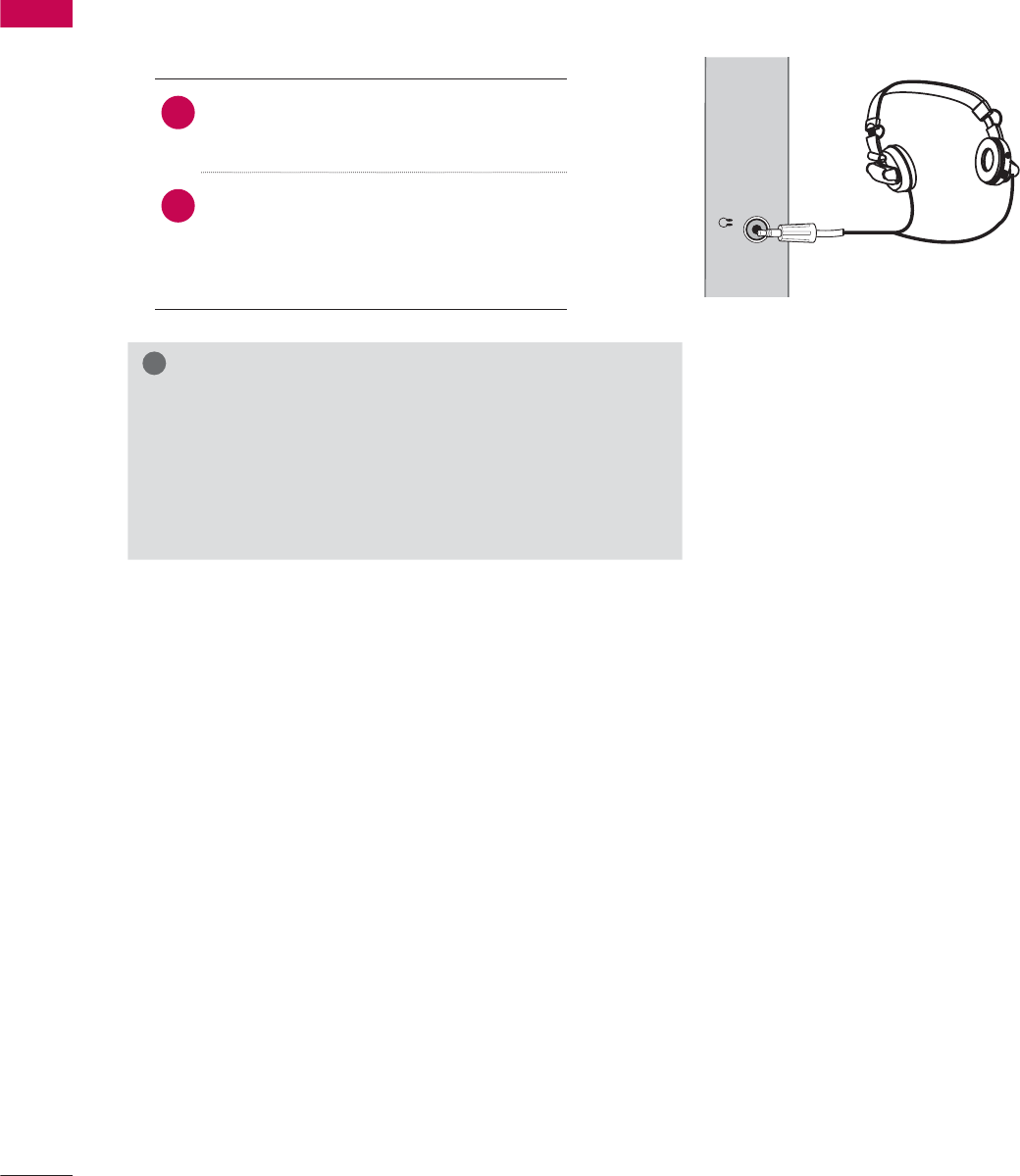
HEADPHONE SETUP (FOR LED LCD TV/LCD TV)
H/P
You can listen to the sound through the headphone.
1. How to connect
1Plug the headphone into the head-
phone socket.
2To adjust the headphone volume,
press the VOL +/- button. If you
press the MUTE button, the sound
from the headphone is switched off.
!
NOTE
ŹAUDIO menu options are disabled when connecting a
headphone.
ŹWhen changing AV MODE with a headphone con-
nected, the change is applied to video but not to audio.
ŹOptical Digital Audio Out is not available when con-
necting a headphone.
47
EXTERNAL EQUIPMENT SETUP
()
L
ESS
T
ROL
(RGB/DVI)
/DVI IN
2
3
1
VIDEO
AUDIO
L(MONO)
R
VIDEO AUDIO
COMPONENT INAV IN 1
AUDIO IN
2
1
AUDIO OUT
YP
B
P
R
L R
OPTICAL DIGITAL
(
)
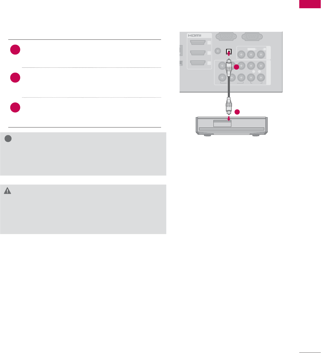
AUDIO OUT CONNECTION
Send the TV’s audio to external audio equipment via the Audio Output port.
If you want to enjoy digital broadcasting through 5.1-channel speakers, connect the OPTICAL DIGITAL
AUDIO OUT terminal on the back of TV to a Home Theater (or amp).
!
NOTE
ŹWhen connecting with external audio equipment, such
as amplifiers or speakers, you can turn the TV speakers
off in the menu. (Źp.150)
CAUTION
ŹDo not look into the optical output port. Looking at
the laser beam may damage your vision.
ŹAudio with ACP (Audio Copy Protection) function may
block digital audio output.
1. How to connect
1Connect one end of the optical cable to the
TV port of OPTICAL DIGITAL AUDIO OUT.
2Connect the other end of the optical cable to
the digital audio input on the audio equip-
ment.
3Set the “TV Speaker option - Off” in the
AUDIO menu. (Źp.150). See the external audio
equipment instruction manual for operation.
1
2
EXTERNAL EQUIPMENT SETUP
EXTERNAL EQUIPMENT SETUP
48
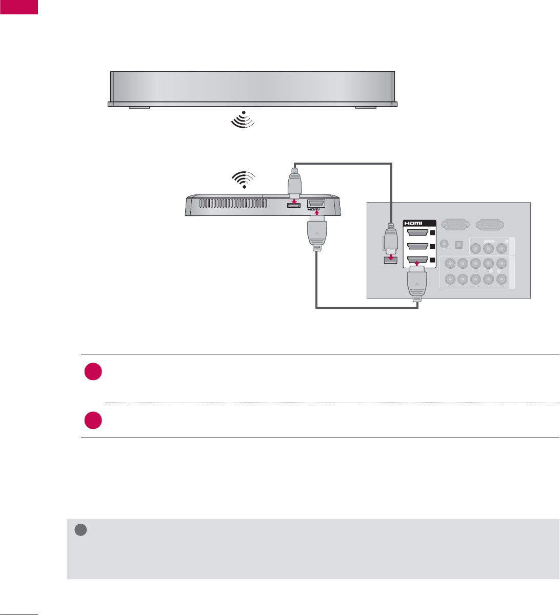
EXTERNAL EQUIPMENT WIRELESS CONNECTION
(OPTIONAL EXTRAS, EXCEPT 42/42LE5350)
LG TVs with a Wireless Control port support the LG Wireless Media Box, which is sold separately.
When you connect the wireless ready dongle (included with the media box) to the TV, external devices
can be connected to the LG Wireless Media Box and video and audio will be sent to the TV wirelessly.
RGB IN (PC)
LAN
(RGB/DVI)
VIDEO
AUDIO
L(MONO)
R
VIDEO AUDIO
COMPONENT INAV IN 1
AUDIO IN
AUDIO OUT
2
1
WIRELESS
CONTROL
OUT
WIRELESS
CONTROL
/DVI IN
2
3
1
YP
B
P
R
L R
OPTICAL DIGITAL
RS-232C IN
(
SERVICE ONLY)
ꔡ
1. How to connect
1Connect the WIRELESS CONTROL jack of the Wireless Ready Dongle to the WIRELESS
CONTROL jack on the TV.
2Connect HDMI OUT jack of the Wireless Ready Dongle to the HDMI IN jack on the TV.
2. How to use
ᯫ
Select the desired input source on the TV using the INPUT button on the remote control.
ᯫ
Refer to the Wireless Media Box manual for operating instructions.
!
NOTE
ŹWhen using the external device connected to the Wireless Media Box, some functions of the TV
menu may not work.
49
EXTERNAL EQUIPMENT SETUP
LAN
IRELESS
O
NTROL
/DVI IN
2
3
1
VIDEO
AUDIO
L(MONO)
R
VIDEO AUDIO
COMPONENT INAV IN 1
AUDIO OUT
2
1
RGB IN (PC)
RGB OUTPUT
AUDIO
(RGB/DVI)
AUDIO IN
YP
B
P
R
L R
OPTICAL DIGITAL
RS-232C IN
(
SERVICE ONLY)
ꔡ
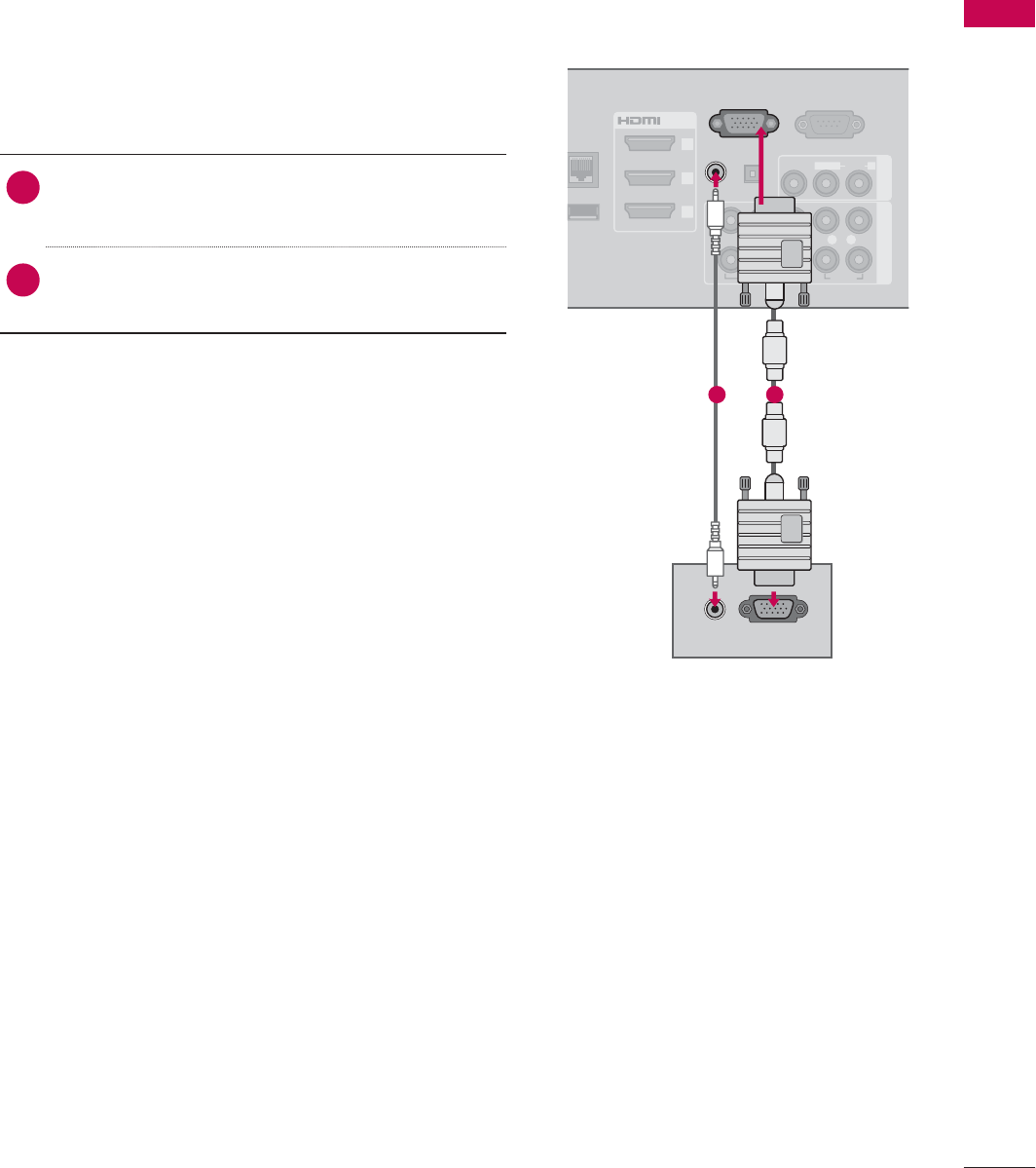
PC SETUP
This TV provides Plug and Play capability, meaning that a PC adjusts automatically to the TV's set-
tings.
1. How to connect
1Connect the VGA output of the PC to the
RGB IN (PC)jack on the TV.
2Connect PC audio output to the AUDIO IN
(RGB/DVI) jack on the TV.
2. How to use
ᯫ
Turn on the PC and the TV.
ᯫ
Select the RGB-PC input source on the TV using
the INPUT button on the remote control.
VGA (D-Sub 15 Pin) Connection
12
EXTERNAL EQUIPMENT SETUP
EXTERNAL EQUIPMENT SETUP
50
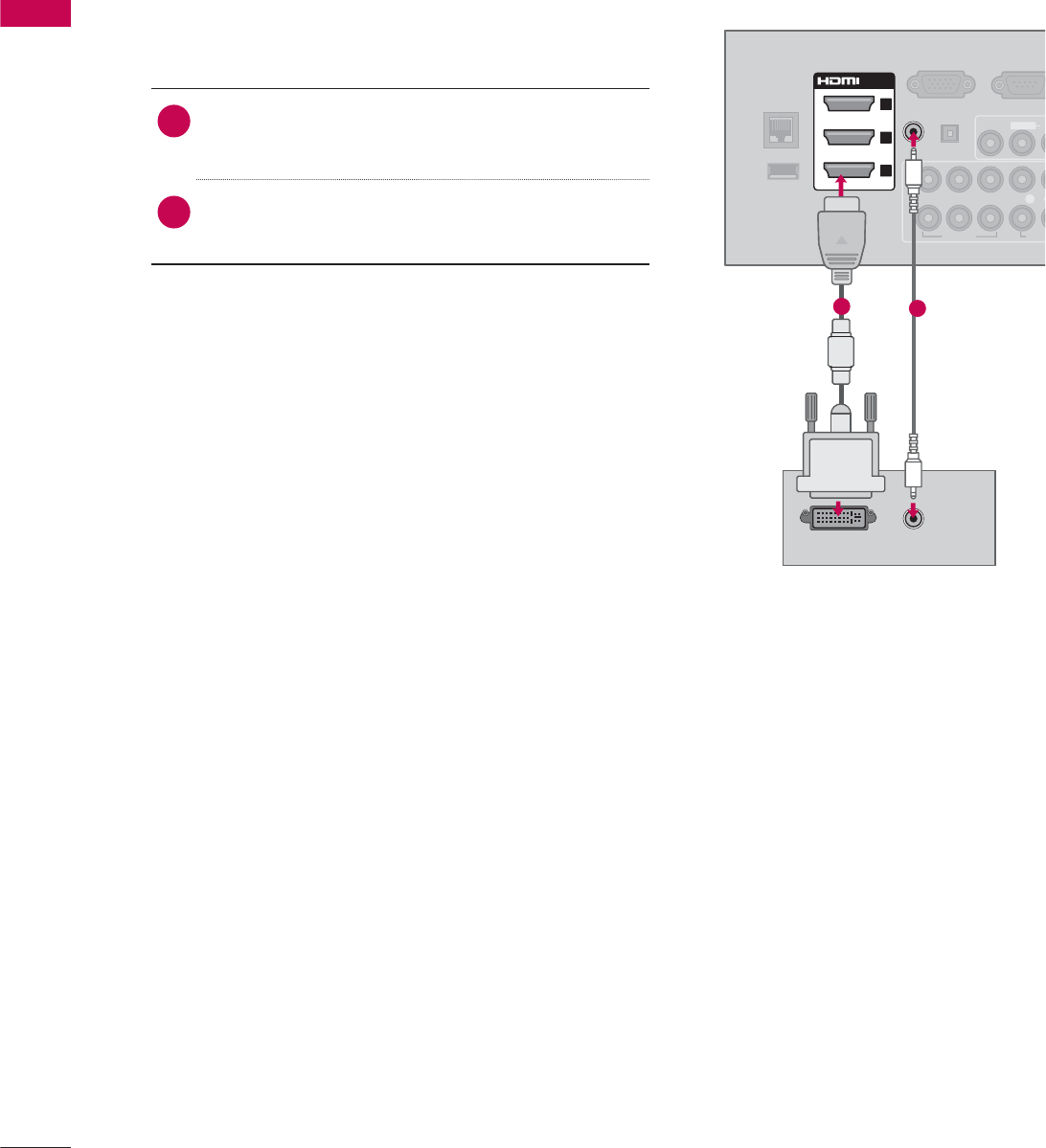
DVI to HDMI Connection
1. How to connect
1Connect the DVI output of the PC to the HDMI/
DVI IN 1,2,3, or 4* jack on the TV.
2Connect the PC audio output to the AUDIO IN
(RGB/DVI) jack on the TV.
2. How to use
ᯫ
Turn on the PC and the TV.
ᯫ
Select the HDMI1,HDMI2,HDMI3, or HDMI4* input
source on the TV using the INPUT button on the
remote control.
DVI OUTPUT AUDIO
RGB IN (PC)
LAN
WIRELESS
CONTROL
VIDEO
A
U
L(MONO)
VIDEO AUDI
AUDIO OUT
2
1
/DVI IN
2
3
1
(RGB/DVI)
AUDIO IN
YP
B
P
R
L
OPTICAL DIGITAL
RS-232C
I
(
SERVICE ON
L
ꔡ
12
* HDMI4: For Plasma TV
51
EXTERNAL EQUIPMENT SETUP
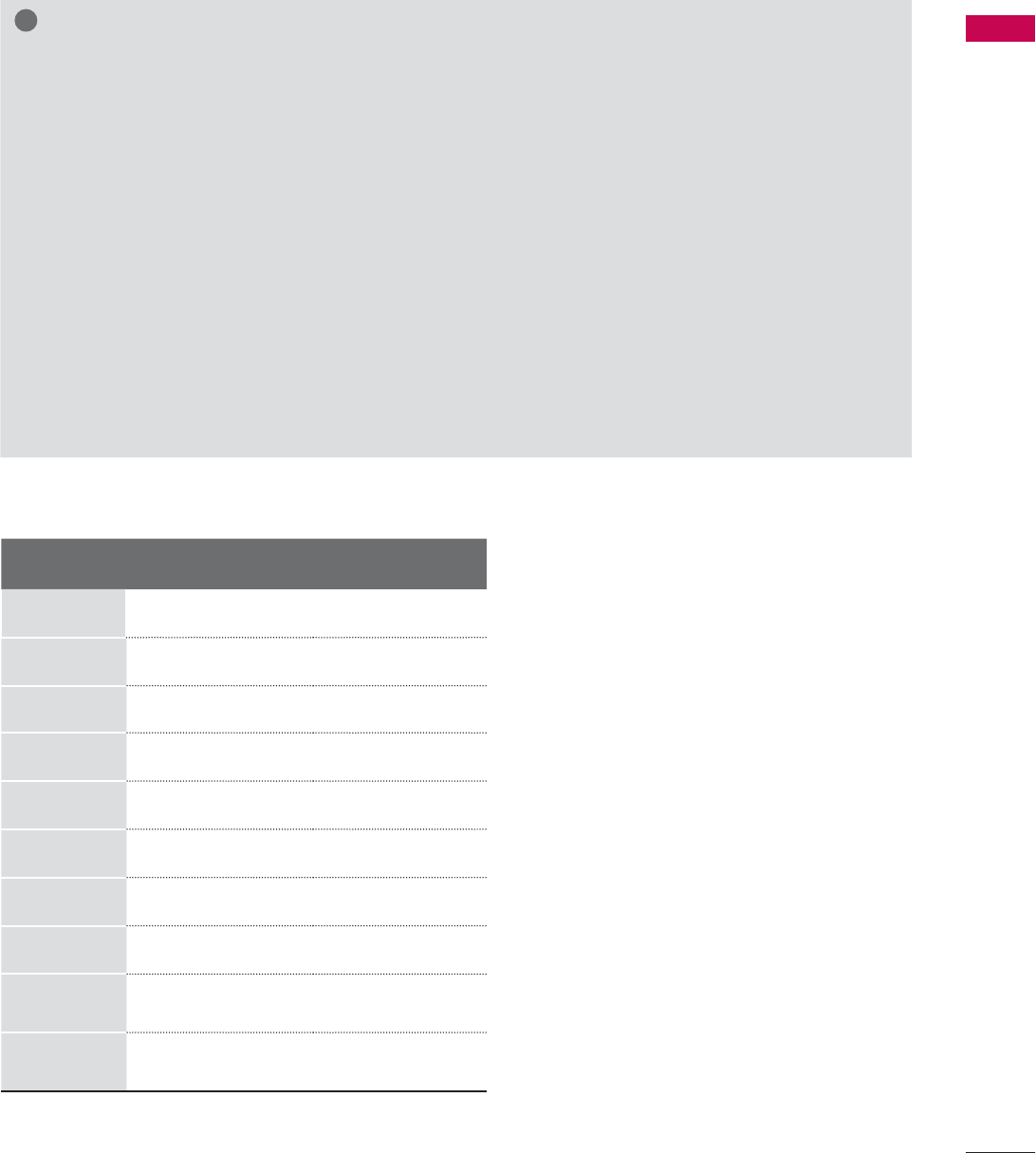
Supported Display Specifications (RGB-PC, HDMI-PC)
!
NOTE
ŹTo get the the best picture quality, adjust the PC graphics card to 1920x1080.
ŹDepending on the graphics card, DOS mode may not work if a HDMI to DVI Cable is in use.
ŹIn PC mode, there may be noise associated with the resolution, vertical pattern, contrast or bright-
ness. If noise is present, change the PC output to another resolution, change the refresh rate to
another rate or adjust the brightness and contrast on the PICTURE menu until the picture is clear.
ŹAvoid keeping a fixed image on the screen for a long period of time. The fixed image may become
permanently imprinted on the screen.
ŹThe synchronization input form for Horizontal and Vertical frequencies is separate.
ŹDepending on the graphics card, some resolution settings may not allow the image to be posi-
tioned on the screen properly.
ŹIf you experience overscan issues when using HDMI-PC 1920x1080, change aspect ratio to Just
scan.
ŹWhen selecting HDMI-PC, set the “Input Label - PC” in the OPTION menu.
Resolution Horizontal
Frequency (kHz)Vertical
Frequency (Hz)
640x350 31.468 70.09
720x400 31.469 70.08
640x480 31.469 59.94
800x600 37.879 60.31
1024x768 48.363 60.00
1280x768 47.776 59.87
1360x768
47.712 60.015
1280x1024
63.981 60.02
1920x1080
RGB-PC
66.587 59.934
1920x1080
HDMI-PC
67.50 60.00
EXTERNAL EQUIPMENT SETUP
EXTERNAL EQUIPMENT SETUP
52
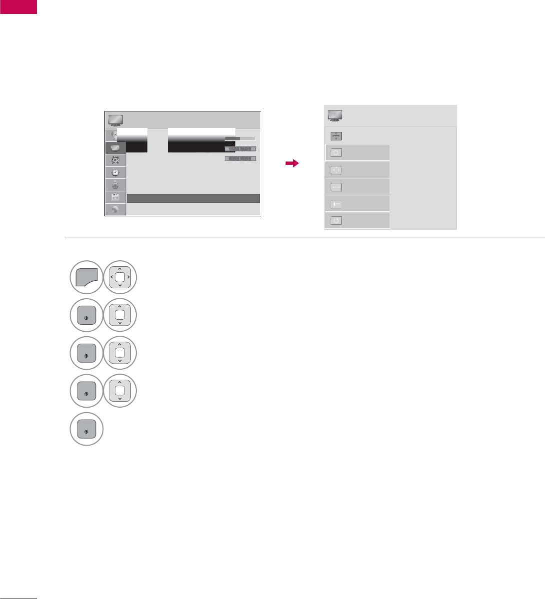
Screen Setup for PC mode
You can choose the resolution in RGB-PC mode.
The Position, Phase, and Size can also be adjusted.
You can choose this option only when the PC resolution is set to 1024X768, 1280X768 or 1360X768.
Selecting Resolution
ᯡ[
۳[
۳[
$XWR&RQILJ
5HVROXWLRQ
3RVLWLRQ
6L]H
Phase
Reset
6&5((1
ᯒ0RYHᰙ3UHY
1
MENU
Select PICTURE.
2
ENTER
Select Screen (RGB-PC).
3
ENTER
Select Resolution.
4
ENTER
Select the desired resolution.
5
ENTER
3,&785( ᯒ0RYHᯙ(QWHU
ᯐ
ᯙ
ؒ&RORU
ؒ7LQW
ؒ&RORU7HPS
ؒ$GYDQFHG&RQWURO
ؒ3LFWXUH5HVHW
ؒ7UX0RWLRQ
ؒ6FUHHQ5*%3&
ؒ/('/RFDO'LPPLQJ2Q
R*
W&
53
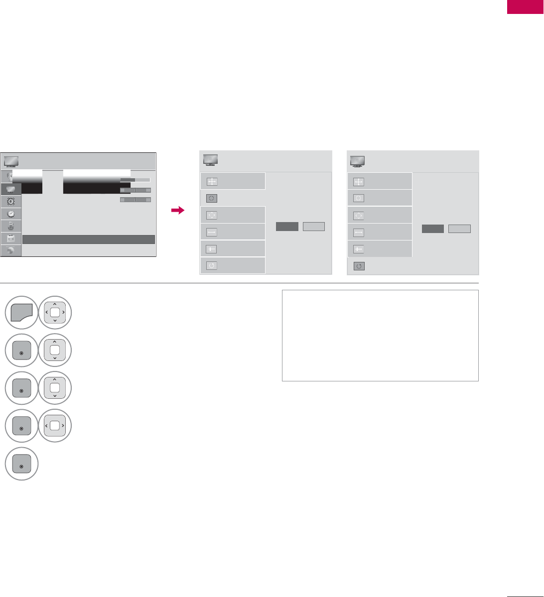
EXTERNAL EQUIPMENT SETUP
Automatically adjusts picture position and minimizes image instability. After adjustment, if the image
is still not correct, try using the manual settings or a different resolution or refresh rate on the PC.
Auto Configure
1
MENU
Select PICTURE.
2
ENTER
Select Screen (RGB-PC).
3
ENTER
Select Auto Config. or
Reset.
4
ENTER
Select Yes.
5
ENTER
ᯫ
If the position of the image is still not
correct, try Auto adjustment again.
ᯫ
If picture needs to be adjusted again
after Auto adjustment in RGB-PC,
you can adjust the Position,Size or
Phase.
$XWR&RQILJ
5HVROXWLRQ
3RVLWLRQ
6L]H
Phase
Reset
$XWR&RQILJ
Yes 1R
6&5((1
ᯒ0RYHᰙ3UHY
3,&785( ᯒ0RYHᯙ(QWHU
ᯐ
ᯙ
ؒ&RORU
ؒ7LQW
ؒ&RORU7HPS
ؒ$GYDQFHG&RQWURO
ؒ3LFWXUH5HVHW
ؒ7UX0RWLRQ
ؒ6FUHHQ5*%3&
ؒ/('/RFDO'LPPLQJ2Q
R*
W&
Returns Position,Size, and Phase to the default initial settings.
This feature operates only in RGB-PC mode.
Screen Reset (Reset to original initial values)
$XWR&RQILJ
3RVLWLRQ
5HVROXWLRQ
6L]H
Phase
Reset
7R6HW
Yes 1R
6&5((1
ᯒ0RYHᰙ3UHY
EXTERNAL EQUIPMENT SETUP
EXTERNAL EQUIPMENT SETUP
54
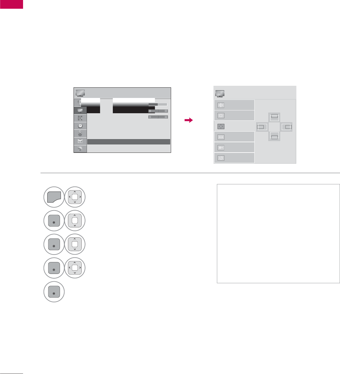
If the picture is not clear after auto adjustment or if text is shaking, adjust the picture phase manually.
This feature operates only in RGB-PC mode.
Adjustment for screen Position, Size, and Phase
1
MENU
Select PICTURE.
2
ENTER
Select Screen (RGB-PC).
3
ENTER
Select Position,Size, or Phase.
4
ENTER
Make appropriate adjustments.
5
ENTER
ᯫ
Position: This function is to adjust
picture to left/right and up/down as
you prefer.
ᯫ
Size: This function is to minimize any
vertical bars or stripes visible on the
screen background. And the horizon-
tal screen size will also change.
ᯫ
Phase: This function allows you to
remove any horizontal noise and
clear or sharpen the image of char-
acters.
$XWR&RQILJ
5HVROXWLRQ
3RVLWLRQ
6L]H
Phase
Reset
6&5((1
ᯒ0RYHᰙ3UHY
3,&785( ᯒ0RYHᯙ(QWHU
ᯐ
ᯙ
ؒ&RORU
ؒ7LQW
ؒ&RORU7HPS
ؒ$GYDQFHG&RQWURO
ؒ3LFWXUH5HVHW
ؒ7UX0RWLRQ
ؒ6FUHHQ5*%3&
ؒ/('/RFDO'LPPLQJ2Q
R*
W&
ۻ
܁۽
ۿ
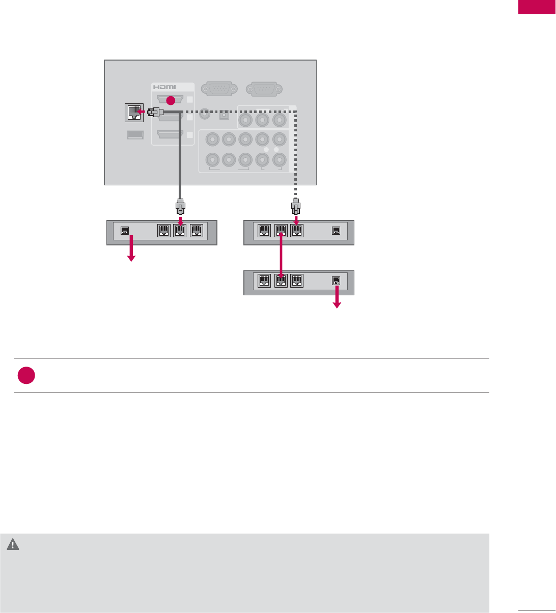
55
EXTERNAL EQUIPMENT SETUP
RGB IN (PC)
WIRELESS
CONTROL
(RGB/DVI)
/DVI IN
2
3
1
VIDEO
AUDIO
L(MONO)
R
VIDEO AUDIO
COMPONENT INAV IN 1
AUDIO IN
AUDIO OUT
2
1
LAN
YP
B
P
R
L R
OPTICAL DIGITAL
RS-232C IN
(
SERVICE ONLY)
ꔡ
Broadband modem
Broadband modem
Router
Broadband Service
Broadband Service
NETWORK SETUP
This TV can be connected to a local area network (LAN) via the LAN port. After making the physical
connection, the TV needs to be set up for network communication.
CAUTION
ŹDo not connect a modular phone cable to the LAN port.
ŹSince there are various connection methods, please follow the specifications of your telecommu-
nication carrier or internet service provider.
1. How to connect
1Connect the LAN port of the Modem or Router to the LAN port on the TV.
2. How to use
ᯫ
Select “Network Setting” in the NETWORK menu.
ᯫ
After connecting the LAN port, use the NETCAST menu.
ᯫ
For more information about NETCAST setup and troubleshooting, visit http://lgknowledgebase.
com. Search for NETCAST.
Wired Network Connection
1
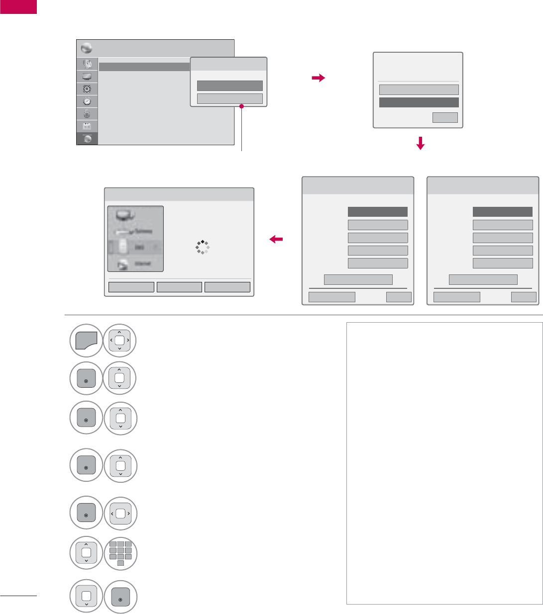
EXTERNAL EQUIPMENT SETUP
EXTERNAL EQUIPMENT SETUP
56
ᯫ
This feature requires an always-on
broadband internet connection.
ᯫ
You do not need to connect to a PC
to use this function.
ᯫ
If Network Setting is not working,
check your network conditions. Check
the LAN cable and make sure your
router has DHCP turned on if you
wish to use the Auto Setting.
ᯫ
If the Network Setting is not com-
pleted, network may not operate nor-
mally.
ᯫ
IP Auto Setting: Select it if there is a
DHCP server on the local area net-
work (LAN) via wired connection, the
TV will automatically be allocated an
IP address. If you’re using a broad-
band router or broadband modem
that has a DHCP (Dynamic Host
Configuration Protocol) server func-
tion. The IP address will automati-
cally be determined.
ᯫ
IP Manual Setting: Select it if there is
no DHCP server on the network and
you want to set the IP address manu-
ally.
1(7:25. ᯒ0RYHᯙ(QWHU
ؒ1HWZRUN6HWWLQJ :LUHG
ؒ1HWZRUN6WDWXV ,QWHUQHWLVFRQQHFWHG
ؒ/HJDO1RWLFH
ؒ(61
Wired Network Setup
1
MENU
Select NETWORK.
2
ENTER
Select Network Setting.
3
ENTER
Select Wired.
4
ENTER
If you already set Network Setting:
Select Resetting. The new connection
settings resets the current network
settings.
5
ENTER
Select IP Auto Setting or IP Manual
Setting.
12
ABC
3
DEF
4
GHI
5
JKL
6
MNO
7
PQRS
8
TUV
0
9
WXYZ
When Selecting IP Manual Setting:
IP addresses will need to be input
manually.
6
ENTER
Select Enter.
IP Auto Setting
If you already set the
Network Setting
IP Manual Setting
If wired and wireless networks are both available, wired is the preferred method.
After making a physical connection, a small number of home networks may require the TV network
settings to be adjusted.
For detail information, contact your internet provider or router manual.
1HWZRUN7\SH
:LUHGQHWZRUNLVUHFRPPHQGHG
:LUHG
:LUHOHVV
1HWZRUN6HWWLQJ
6HOHFWWKH,3VHWWLQJPRGH
,30RGH ܁,3$XWR6HWWLQJ۽
ᯘ,3$GGUHVV
ᯘ6XEQHW0DVN
ᯘ*DWHZD\
ᯘ'166HUYHU
ᰙ3UHYLRXV
(QWHU
᰿([LW
1HWZRUN6HWWLQJ
,QVHUWWKH,3DGGUHVV
,30RGH ܁,30DQXDO6HWWLQJ۽
ᯘ,3$GGUHVV
ᯘ6XEQHW0DVN
ᯘ*DWHZD\
ᯘ'166HUYHU
ᰙ3UHYLRXV
(QWHU
᰿([LW
1HWZRUN6WDWXV
1HWZRUNFRQQHFWLQJ
6HWWLQJ 7HVW &ORVH
3UHYLRXVVHWWLQJYDOXHH[LVWV'R
\RXZDQWWRFRQQHFWZLWKWKH
SUHYLRXVVHWWLQJ"
(QWHU
5HVHWWLQJ
᰿([LW
ᯙ1H[W
79
Appeared when wired and
wireless are simultaneously
connected.

57
EXTERNAL EQUIPMENT SETUP
!
NOTE
ŹFor more information about NETCAST setup
and troubleshooting, visit http://lgknowledge-
base.com. Search for NETCAST.
ŹUse a standard LAN cable with this TV. Cat5
or better with a RJ45 connector.
ŹMany network connection problems during set
up can often be fixed by re-setting the router
or modem. After connecting the player to the
home network, quickly power off and/or dis-
connect the power cable of the home network
router or cable modem. Then power on and/or
connect the power cable again.
ŹDepending on the internet service provider
(ISP), the number of devices that can receive
internet service may be limited by the appli-
cable terms of service. For details, contact
your ISP.
ŹLG is not responsible for any malfunction of
the TV and/or the internet connection feature
due to communication errors/malfunctions
associated with your broadband internet con-
nection, or other connected equipment.
ŹLG is not responsible for problems within your
internet connection.
ŹSome content available through the network
connection may not be compatible with the
TV. If you have questions about such content,
please contact the producer of the content.
ŹYou may experience undesired results if the
network connection speed does not meet the
requirements of the content being accessed.
ŹSome internet connection operations may not
be possible due to certain restrictions set by
the Internet service provider (ISP) supplying
your broadband Internet connection.
ŹAny fees charged by an ISP including, without
limitation, connection charges are your respon-
sibility.
ŹA 10 Base-T or 100 Base-TX LAN port is
required for connection to this TV. If your inter-
net service does not allow for such a connec-
tion, you will not be able to connect the TV.
ŹA DSL modem is required to use DSL service
and a cable modem is required to use cable
modem service. Depending on the access
method of and subscriber agreement with
your ISP, you may not be able to use the inter-
net connection feature contained in this TV or
you may be limited to the number of devices
you can connect at the same time. (If your ISP
limits subscription to one device, this TV may
not be allowed to connect when a PC is
already connected.)
ŹThe use of a “Router” may not be allowed or
its usage may be limited depending on the
policies and restrictions of your ISP. For details,
contact your ISP directly.
ŹThe wireless network operates at 2.4 GHz
radio frequencies that are also used by other
household devices such as cordless tele-
phone, Bluetooth® devices, microwave oven,
and can be affected by interference from
them. It can be interrupted by the device
using 5Ghz radio frequencies. It is same
device with LG wireless media box, cordless
telephone, other Wi-Fi device.
ŹIt may decrease the service speed using
Wireless network by surrounding wireless con-
dition.
ŹTurn off all unused network equipment in your
local home network. Some devices may gen-
erate network traffic.
ŹIn some instances, placing the access point or
wireless router higher up away from the floor
may improve the reception.
ŹThe reception quality over wireless depends
on many factors such as type of the access
point, distance between the TV and access
point, and the location of the TV.
ŹWhen connecting internet through the wired/
wireless sharing machine, it may interrupt the
connection because of the use limitation and
confirmation of service company.
ŹTo connect wireless AP, an AP that supports
the wireless connection is necessary, and the
wireless connection function of the AP needs
to be activated. Please enquire to the AP sup-
plier for the possibility of AP wireless connec-
tions.
ŹPlease verify the security settings of AP SSID
for wireless AP connection, and enquire to the
AP supplier for the AP SSID security settings.
ŹThe TV can become slower or malfunction
with wrong settings of network equipments
(wired/wireless router, hub, etc). Please install
correctly by referring to the manual of the
equipment, and set the network.
ŹWhen AP is set to include 802.11 n, and if
Encryption is designated as WEP(64/128bit)
or WPA(TKIP/AES), the connection may not
be possible. There may be different connec-
tion methods according to the AP manufac-
turers.
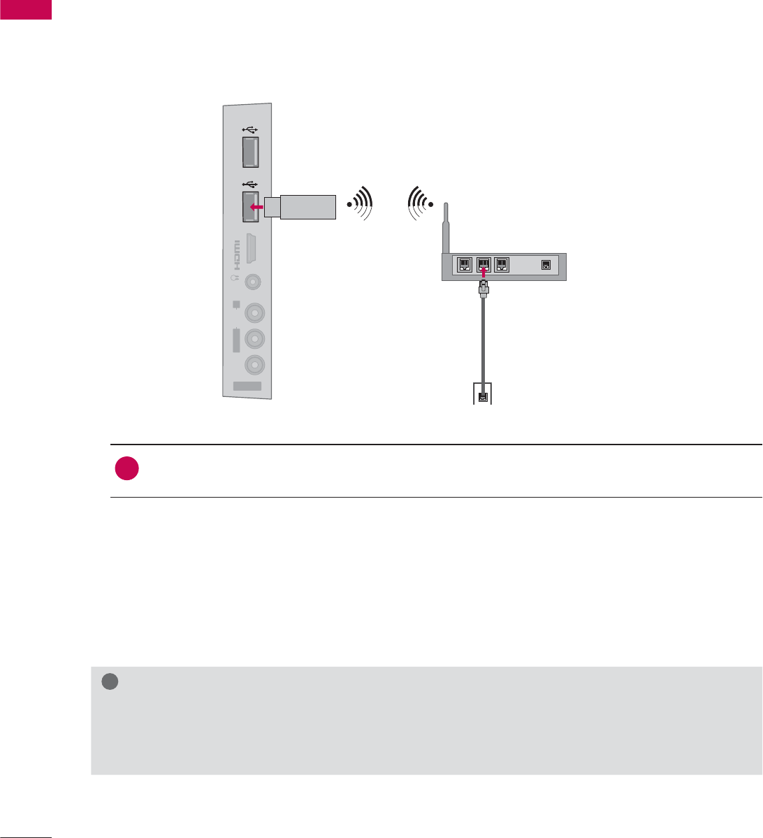
EXTERNAL EQUIPMENT SETUP
EXTERNAL EQUIPMENT SETUP
58
IN 4
AV IN 2
VIDEO
AUDIO
L(MONO)
R
H/P USB IN 1 USB IN 2
The LG Wireless LAN for Broadband/DLNA Adaptor, which is sold separately, allows the TV to connect
to a wireless lan network.
The network configuration and connection method may vary depending on the equipment in use and
the network environment. Refer to the setup instructions supplied with your access point or wireless
router for detailed connection steps and network settings.
1. How to connect
1Connect the “LG Wireless LAN for Broadband/DLNA Adaptor (sold separately)” to the USB
IN 1 or 2port on the TV.
2. How to use
ᯫ
Select “Network Setting” in the NETWORK menu.
ᯫ
After connecting, you can use the NETCAST menu.
Wireless Network Connection (Except 42/47LE5350)
!
NOTE
ŹFor enjoying pictures, music, or video stored in the PC using the router, the use of wired port in
the router is recommended.
ŹWhen the wireless port of the router is used, there may be restrictions for some functions.
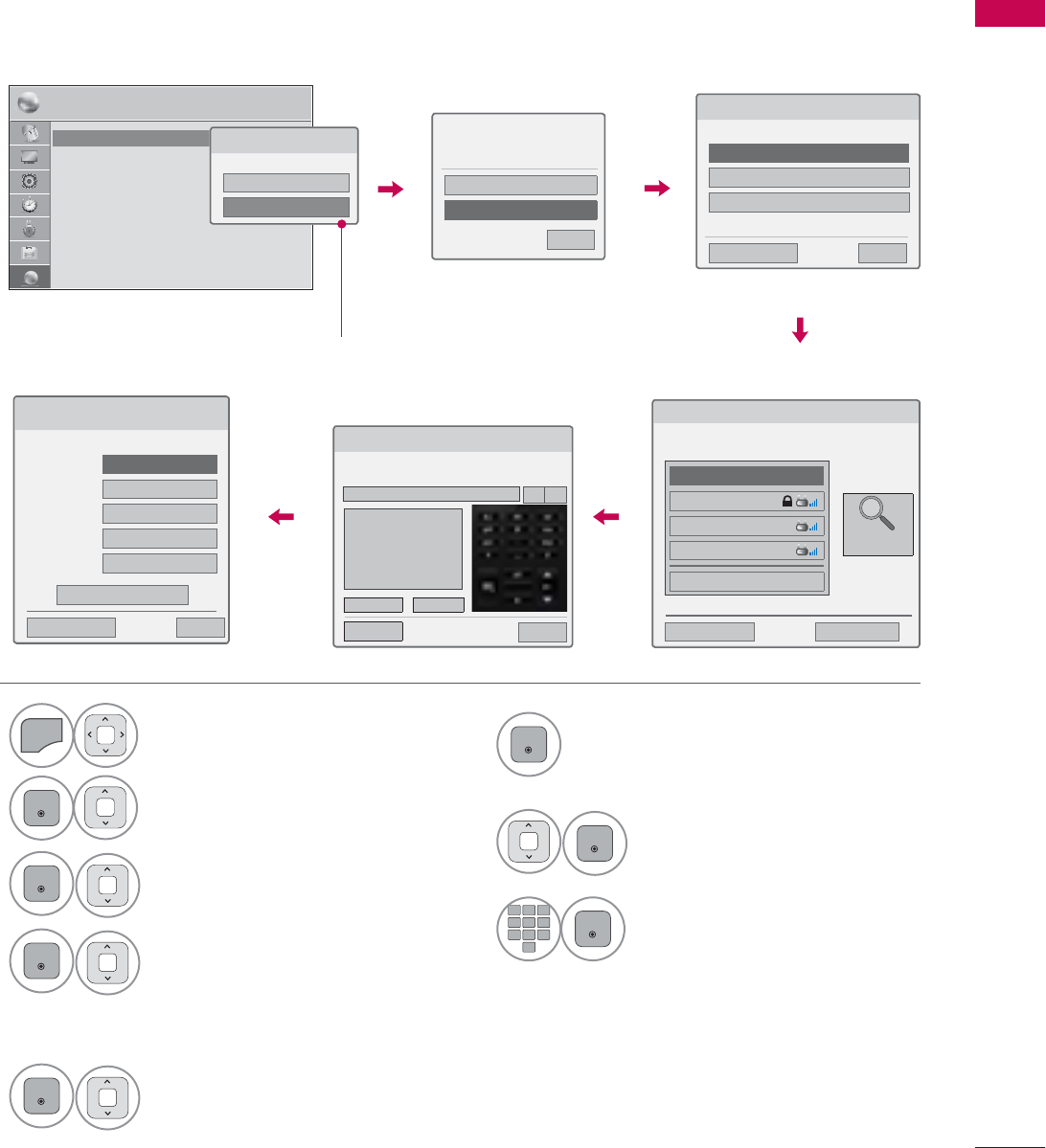
59
EXTERNAL EQUIPMENT SETUP
Setting up the AP (Access Point) or the wireless router is required before connecting the TV to the
network.
Wireless Network Setup (Except 42/47LE5350)
6
ENTER
Scan the all available AP (Access
Point) or wireless routers within range
and display them as a list.
7
ENTER
Select an AP (Access Point) or
wireless router on the list.
(If your AP is locked, insert the
security key of AP).
8
12
ABC
3
DEF
4
GHI
5
JKL
6
MNO
7
PQRS
8
TUV
0
9
WXYZ
ENTER
Input the security key of AP.
1
MENU
Select NETWORK.
2
ENTER
Select Network Setting.
3
ENTER
Select Wireless.
4
ENTER
If you already set Network
Setting: Select Resetting.
The new connection settings
resets the current network set-
tings.
5
ENTER
Select Setting from the AP list.
1(7:25. ᯒ0RYHᯙ(QWHU
ؒ1HWZRUN6HWWLQJ :LUHG
ؒ1HWZRUN6WDWXV ,QWHUQHWLVFRQQHFWHG
ؒ/HJDO1RWLFH
ؒ(61
1HWZRUN7\SH
:LUHGQHWZRUNLVUHFRPPHQGHG
:LUHG
:LUHOHVV
6HOHFWLQJWKHZLUHOHVVQHWZRUNVHWWLQJW\SH
6HOHFWWKHZLUHOHVVQHWZRUNVHWWLQJW\SH
6HWWLQJIURPWKH$3OLVW
6LPSOHVHWWLQJ:36EXWWRQPRGH
6HWWLQJ$GKRFQHWZRUN
ᰙ3UHYLRXV ᰿([LW
ᯙ1H[W
6HOHFWLQJ$3
ᰙ3UHYLRXV ᰿([LW
ᯙ1H[W
6HOHFW$3\RXZDQWWRFRQQHFW
PDJH1/1
,QSXWWKHQHZ66,'
LSWLPH
ASW
1HWZRUN
ᯕ&RQQHFWLQJZLWK3,1PRGH
$FFHVV3RLQW
6HDUFK
9Repeat step 4-5 on P.56.
If your AP is locked
If you already set the
Network Setting
3UHYLRXVVHWWLQJYDOXHH[LVWV'R
\RXZDQWWRFRQQHFWZLWKWKH
SUHYLRXVVHWWLQJ"
(QWHU
5HVHWWLQJ
᰿([LW
ᯙ1H[W
,QVHUWLQJWKHVHFXULW\NH\
,QVHUWWKHVHFXULW\NH\RI$3
,QVHUWa$6&,,FKDUDFWHUV
(QWHU &DQFHO
ᰙ3UHY ᰿([LW
܁۽
1HWZRUN6HWWLQJ
6HOHFWWKH,3VHWWLQJPRGH
,30RGH ܁,3$XWR6HWWLQJ۽
ᯘ,3$GGUHVV
ᯘ6XEQHW0DVN
ᯘ*DWHZD\
ᯘ'166HUYHU
ᰙ3UHYLRXV
(QWHU
᰿([LW
Appeared when wired and wireless
are simultaneously connected.
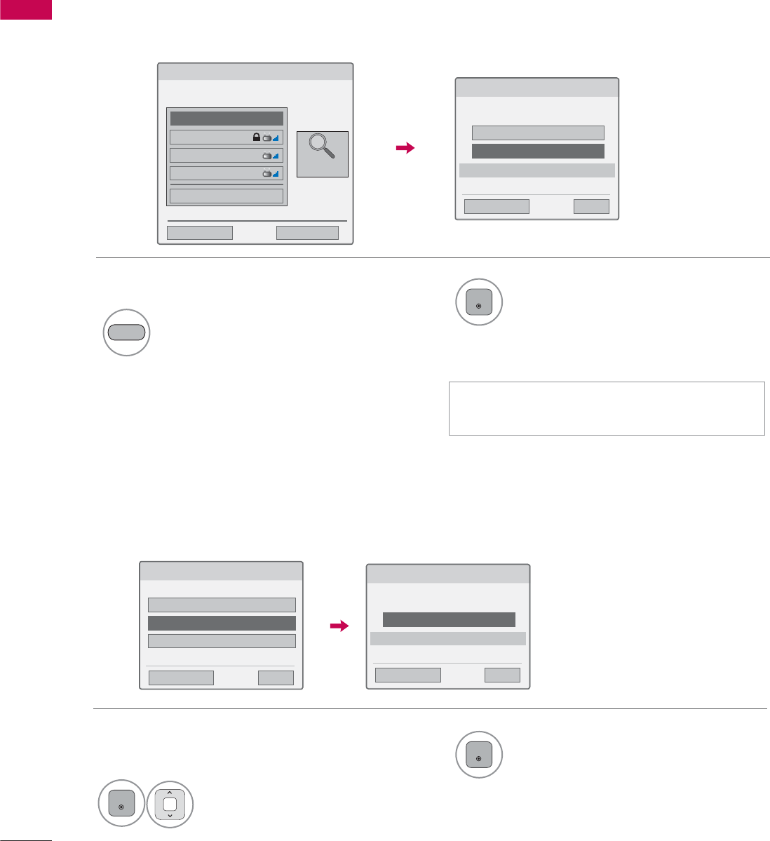
EXTERNAL EQUIPMENT SETUP
EXTERNAL EQUIPMENT SETUP
60
If you want to connect the AP (Access Point) or router with PIN, use this feature.
If your access point or wireless router that supports PIN or WPS (Wi-Fi Protected Setup), it’s available
to use your access point or wireless router within 120 counts. You do not need to know the access
point name (SSID: Service Set Identifier) and security code of your access point or wireless router.
When a security code is already set
PIN (Personal Identification Number)
Simple setting (WPS-button mode)
ᯫ
PIN number is the unique 8 digit number
of the dongle.
&RQQHFWLQJZLWK3,1PRGH
,QVHUW3,1QXPEHUDWWKH$3ZHESDJHDQG
SUHVV؋&RQQHFW،EXWWRQ
3,118%0(5
&RQQHFW
ᰙ3UHYLRXV
)RUPRUHLQIRUPDWLRQFKHFNWKH$3PDQXDO
᰿([LW
ᯙ1H[W
6LPSOHVHWWLQJ:36EXWWRQPRGH
3UHVV3%&0RGHEXWWRQRI$3DQGSUHVV؋&RQQHFW،EXWWRQ
&RQQHFW
ᰙ3UHYLRXV
&DXWLRQ&KHFNLI3%&PRGHEXWWRQLVDYDLODEOHIRU\RXU$3
᰿([LW
ᯙ1H[W
6HOHFWLQJ$3
ᰙ3UHYLRXV ᰿([LW
ᯙ1H[W
6HOHFW$3\RXZDQWWRFRQQHFW
PDJH1/1
,QSXWWKHQHZ66,'
LSWLPH
ASW
1HWZRUN
ᯕ&RQQHFWLQJZLWK3,1PRGH
$FFHVV3RLQW
6HDUFK
2Connect the acccess point with PIN
mode.
4
ENTER
Select Connect.
RED
1Repeat step 1-6 on P.59.
3You can see the Network ID and Security Key
on your TV screen.
Enter the PIN number to your device.
6HOHFWWKHZLUHOHVVQHWZRUNVHWWLQJW\SH
6HOHFWWKHZLUHOHVVQHWZRUNVHWWLQJW\SH
6HWWLQJIURPWKH$3OLVW
6LPSOHVHWWLQJ:36EXWWRQPRGH
6HWWLQJ$GKRFQHWZRUN
ᰙ3UHYLRXV ᰿([LW
ᯙ1H[W
1Repeat step 1-4 on P.59. 3
ENTER
Select Connect.
2
ENTER
Select Simple setting (WPS-
button mode).
5Repeat step 4-5 on P.56.
4Repeat step 4-5 on P.56.
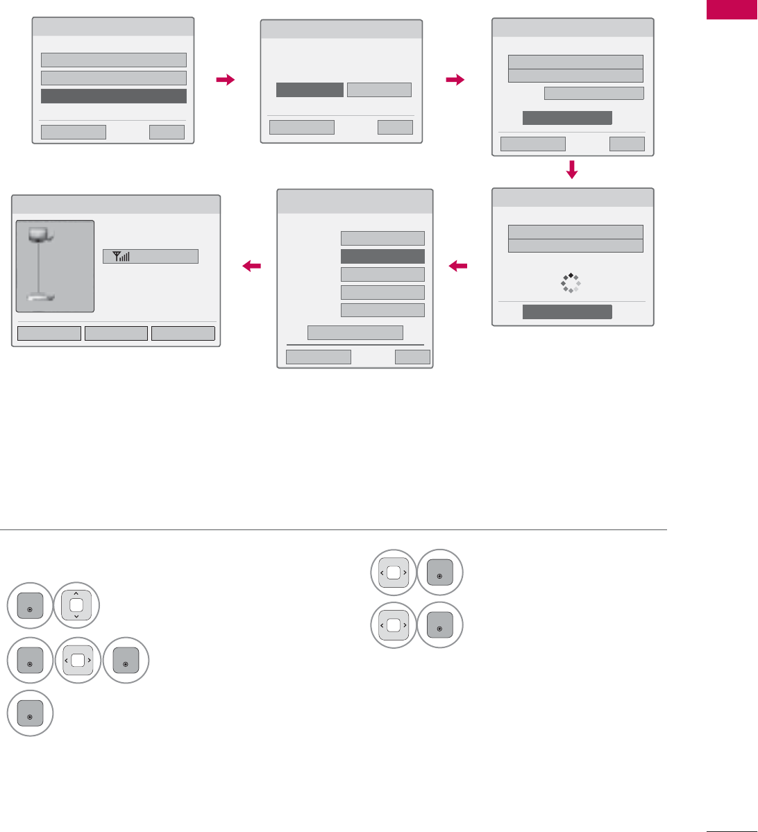
61
EXTERNAL EQUIPMENT SETUP
This is the method of communicating directly with the machine to communicate without AP.
This is the same as connecting two PCs with a cross cable.
AD-hoc Mode
1Repeat step 1-3 on P.59.
6HOHFWLQJWKHZLUHOHVVQHWZRUNVHWWLQJW\SH
6HOHFWWKHZLUHOHVVQHWZRUNVHWWLQJW\SH
6HWWLQJIURPWKH$3OLVW
6LPSOHVHWWLQJ:36EXWWRQPRGH
6HWWLQJ$GKRFQHWZRUN
ᰙ3UHYLRXV ᰿([LW
ᯙ1H[W
6HWWLQJ$GKRFQHWZRUN
)HDWXUHVXVLQJH[LWLQJQHWZRUNFDQEHXQDYDLODEOH'R\RX
ZDQWWRFKDQJHQHWZRUNFRQQHFWLRQ"
ᰙ3UHYLRXV ᰿([LW
ᯙ1H[W
(QWHU &DQFHO
6HWWLQJ$GKRFQHWZRUN
,QVHUWWKHVHWWLQJLQIRUPDWLRQLQWRWKHGHYLFH
ᰙ3UHYLRXV ᰿([LW
ᯙ1H[W
1HWZRUN,'66,'/*79
6HFXULW\.H\
ᯕ&KDQJLQJWKHVHWWLQJLQIRUPDWLRQ
&RQQHFW
2
ENTER
Select Setting AD-hoc net-
work.
3
ENTER
ENTER
Select Enter.
4
ENTER
Select Connect to connect Ad-hoc
network.
You can see the Network ID and
Security Key on your TV screen.
Enter this Network ID and Security
Key to your device.
If a network may not operate,
change the setting information
using the RED button.
5
ENTER
Insert the IP address.
6
ENTER
Network setting is completed.
Select Close.
1HWZRUN6HWWLQJ
,QVHUWWKH,3DGGUHVV
,30RGH ,30DQXDO6HWWLQJ
ᯘ,3$GGUHVV
ᯘ6XEQHW0DVN
ᯘ*DWHZD\
ᯘ'166HUYHU
ᰙ3UHYLRXV
(QWHU
᰿([LW
1HWZRUN6WDWXV
$GKRFQHWZRUNLVFRQQHFWHG
/*79
0DF$GGUHVV
,3$GGUHVV
6XEQHW0DVN
*DWHZD\
6HWWLQJ 7HVW &ORVH
6LJQDO6WUHQJWK
79
*DWHZD\
6HWWLQJ$GKRFQHWZRUN
,QVHUWWKHVHWWLQJLQIRUPDWLRQLQWRWKHGHYLFH
1HWZRUN,'66,'/*79
6HFXULW\.H\
&DQFHO
&RQQHFWLQJWKH$GKRFQHWZRUN
ᯫ
PC Setting
Internet Protocol(TCP/IP) of PC needs to be set
manually.
IP address, Subnet Mask, and default Gateway
can be set with your own discretion.
i.e) IP address: 192.168.0.1 / Subnet Mask:
255.255.255.0 / default Gateway: 192.168.0.10
ᯫ
TV Setting
Verify IP address and gateway of PC.
Input Gateway address of PC to IP Address, and
IP Address of PC to Gateway, and select Enter.
i.e) IP address: 192.168.0.10 / Subnet Mask:
255.255.255.0 / default Gateway: 192.168.0.1
ᯫ
Example of the PC setting that
supports a wireless network
1. Find a wireless network device in
your PC.
2. Select LGTV10 that appears in
the list. (Select the same name
as the network ID that appears
on your TV screen.)
3. Type 1111111111 in the Inserting
the security key dialog.
(Type the security key that
appears on your TV screen.)
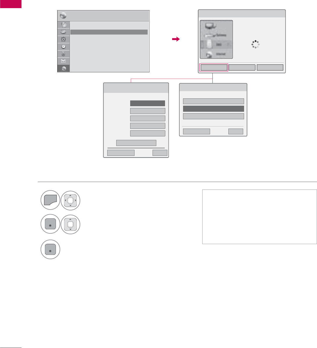
EXTERNAL EQUIPMENT SETUP
EXTERNAL EQUIPMENT SETUP
62
1
MENU
Select NETWORK.
2
ENTER
Select Network Status.
3
ENTER
Check the newtwork status.
Network Status
ᯫ
Setting: Return to the network set-
ting menu or wireless network setting
type menu.
ᯫ
Test: Test the current network status
after setting the network.
ᯫ
Close: Return to the previous menu.
1(7:25. ᯒ0RYHᯙ(QWHU
ؒ1HWZRUN6HWWLQJ :LUHG
ؒ1HWZRUN6WDWXV ,QWHUQHWLVFRQQHFWHG
ؒ/HJDO1RWLFH
ؒ(61
6HOHFWWKHZLUHOHVVQHWZRUNVHWWLQJW\SH
6HOHFWWKHZLUHOHVVQHWZRUNVHWWLQJW\SH
6HWWLQJIURPWKH$3OLVW
6LPSOHVHWWLQJ:36EXWWRQPRGH
6HWWLQJ$GKRFQHWZRUN
ᰙ3UHYLRXV ᰿([LW
ᯙ1H[W
Wired Connection
Wireless Connection
1HWZRUN6HWWLQJ
6HOHFWWKH,3VHWWLQJPRGH
,30RGH ܁,3$XWR6HWWLQJ۽
ᯘ,3$GGUHVV
ᯘ6XEQHW0DVN
ᯘ*DWHZD\
ᯘ'166HUYHU
ᰙ3UHYLRXV
(QWHU
᰿([LW
1HWZRUN6WDWXV
1HWZRUNFRQQHFWLQJ
6HWWLQJ 7HVW &ORVH
79
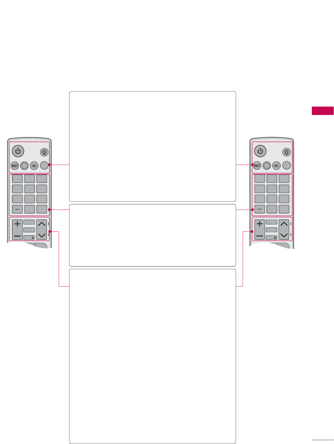
63
WATCHING TV / CHANNEL CONTROL
REMOTE CONTROL FUNCTIONS
When using the remote control, aim it at the remote control sensor on the TV.
The remote control may differ from the images below.
WATCHING TV / CHANNEL CONTROL
ENERGY
CHVOL
12ABC 3 DEF
4 GHI 5JKL 6
MNO
7
PQRS
8 TUV
0
9
WXYZ
P
A
G
E
SAVING
TV
AV MODE
INPUT
LIGHT
FAV
RATIO
MUTE
MARK
DELETE
CHAR/NUM
LIST
FLASHBK
MENU
Q.MENU
ENERGY
CHVOL
12ABC 3 DEF
4 GHI 5 JKL 6
MNO
7
PQRS
8 TUV
0
9
WXYZ
P
A
G
E
SAVING
TV
AV MODE
INPUT
LIGHT
FAV
3D
MUTE
MARK
DELETE
CHAR/NUM
LIST
FLASHBK
MENU
Q.MENU
POWER Turns the TV on from standby or off to
standby.
LIGHT Illuminates the remote control buttons.
(Except 32/42/46/52/60LD550,
47/55LD650)
ENERGY SAVING
Adjusts the Energy Saving setting.
Źp.132
AV MODE Toggles through preset Video and
Audio modes. Źp.88
INPUT Rotates through inputs.
Also switches the TV on from standby.
TV Returns to the last TV channel.
NUMBER button
— (DASH) Used to enter a program number for
multiple program channels such as 2-1,
2-2, etc.
LIST Displays the channel table.
FLASHBK Tunes to the last channel viewed.
VOLUME UP/
DOWN Adjusts the volume.
FAV Set up desired favorite channels list.
MARK Select the input to apply the Picture
Wizard settings. Źp.131
Use to mark or unmark a photo/music/
movie. Źp.105, 110, 116
RATIO Changes the aspect ratio. Źp.128
3D Used for viewing the 3D video. Źp.94
CHAR/NUM Shifts the Character or Number for
internet service.
MUTE Switches the sound on or off.
DELETE Deleted the character or number on the
screen.
CHANNEL
UP/DOWN
Changes the channel.
PAGE
UP/DOWN
Moves from one full set of screen infor-
mation to the next one.
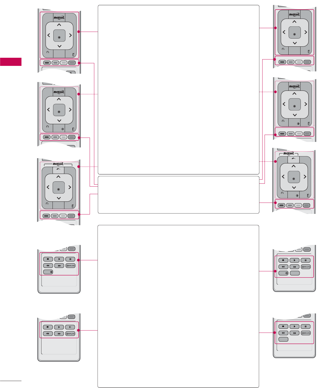
WATCHING TV / CHANNEL CONTROL
WATCHING TV / CHANNEL CONTROL
64
MUTE
BACK
WIDGETS
EXIT
ENTER
DELETE
MENU
L/R SELECT
Q.MENU
MUTE
BACK EXIT
ENTER
MENU
L/R SELECT
Q.MENU
INFO
MUTE
BACK EXIT
ENTER
PREMIUM
3D SETTING
FREEZE
Q.MENU
H
OME
INFO
MUTE
BACK
WIDGETS
EXIT
ENTER
MENU
FREEZE
Q.MENU
FREEZE
INFO
L/R SELECT
INFO RATIO
FREEZE
L/R SELECT
RATIO
USB,
SIMPLINK
Control buttons
ţControls MY MEDIA menu (Movie List,
Photo List, Music List)
ţControls the SIMPLINK compatible
devices.
FREEZE
(For Plasma TV)
Pause the present picture at the screen.
(It doesn’t work at USB Mode and
Simplink.)
The TV returns to normal viewing auto-
matically if no signal is received or no
operation is performed for 5 minutes.
If you keep the screen in Freeze condi-
tion, the residual image can exist.
SIMPLINK See a list of AV devices connected to
TV.
When you toggle this button, the
SIMPLINK menu appears at the screen.
Źp.90
RATIO Changes the aspect ratio. Źp.128
MUTE
BACK
Q.MENU
EXIT
ENTER
PREMIUM
3D SETTING
FREEZE
WIDGETS
H
OME
MUTE
BACK EXIT
ENTER
MENU
Q.MENU
INFO
FREEZE
MENU, HOME Displays the main menu or clears all
on-screen displays and return to TV
viewing.
NETCAST,
PREMIUM
Select the desired NETCAST menu
source.
Źp.123
Q.MENU Opens the list of Quick Menu options.
Źp.71
THUMBSTICK
(Up/Down/Left
Right/ENTER)
Navigates the on-screen menus and
adjusts the system settings to your
preference.
BACK Allows the user to move return one step
in an interactive application or other
user interaction function.
WIDGETS WIDGETS for showing or hiding the
Yahoo! Dock and accessing the Yahoo!
TV Widgets user experience.
INFO Displays channel information at the
bottom of the screen. Źp.81
EXIT Clears all on-screen displays and return
to TV viewing.
COLOR
BUTTON
Access special functions in some
menus.
L/R SELECT,
3D SETTING
Used for viewing the 3D video. Źp.95
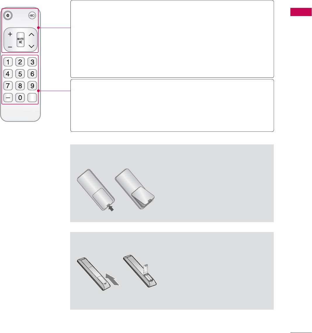
65
WATCHING TV / CHANNEL CONTROL
ᯫ
Open the battery compartment cover
on the back side and install the batter-
ies matching correct polarity.
ᯫ
Install two 1.5V AAA batteries. Don’t
mix old or used batteries with new
ones.
ᯫ
Close cover.
ᯫ
Open the battery compartment cover
on the back side and install the batter-
ies matching correct polarity.
ᯫ
Install two 1.5V AAA batteries. Don’t
mix old or used batteries with new
ones.
ᯫ
Close cover.
Installing Batteries
Installing Batteries
Simple Remote Control
(For 42/47/55LE7500, 47/55LE8500)
CH
FLASHBK
VOL
POWER TV/INPUT
POWER Turns the TV on from standby or off to standby.
TV/INPUT Rotates through inputs.
Also switches the TV on from standby. Źp.83
VOLUME UP/
DOWN Adjusts the volume.
MUTE Switches the sound on or off. Źp.66
CHANNEL
UP/DOWN
Changes the channel.
NUMBER button
— (DASH) Used to enter a program number for multiple program
channels such as 2-1, 2-2, etc.
FLASHBK Tunes to the last channel viewed.
WATCHING TV / CHANNEL CONTROL
WATCHING TV / CHANNEL CONTROL
66
TURNING ON THE TV
CHANNEL SELECTION
VOLUME ADJUSTMENT
Adjust the volume to suit your personal preference.
1First, connect power cord correctly.
At this moment, the TV switches to standby mode.
ᯫ
In standby mode to turn TV on, press the / I,INPUT,CH (ᰜor ᰝ) button on the TV or press
the , INPUT, CH (ᰜor ᰝ),Number (0-9) button on the remote control.
2Select the viewing source by using the INPUT button on the remote control.
3When finished using the TV, press the POWER button on the remote control. The TV reverts
to standby mode.
!
NOTE
Ź If you intend to be away on vacation, disconnect the power plug from the wall power outlet.
Ź If you do not complete the Initial setting, it will appear whenever the TV is switched on until the
Initial setting procedure is completed.
1Press the CH (ᰜor ᰝ) or NUMBER buttons to select a channel number.
1 Press the VOL (+ or -) button to adjust the volume.
2If you want to switch the sound off, press the MUTE button.
3You can cancel the Mute function by pressing the MUTE or VOL (+ or -) button.
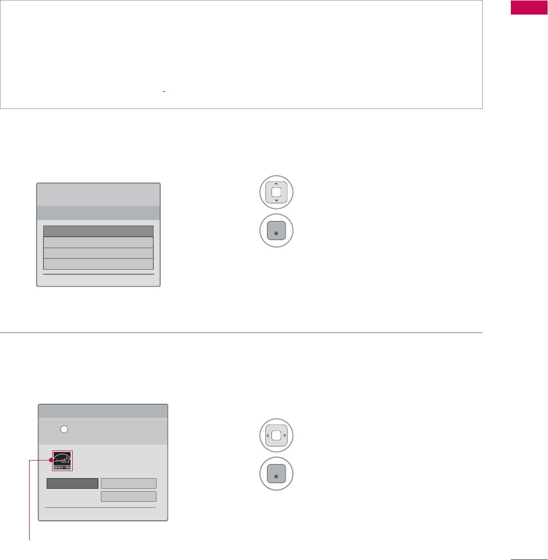
67
WATCHING TV / CHANNEL CONTROL
Step 1. Selecting Language
Step 2. Mode setting
INITIAL SETTING
This Function guides the user to easily set the essential items for viewing the TV for the first time
when purchasing the TV. It will be displayed on the screen when turning the TV on for the first time. It
can also be activated from the user menus.
ᯫ
Default selection is “Home Use”. We recommend setting the TV to “Home Use” mode for the best
picture in your home environment.
ᯫ
“Store Demo” Mode is only intended for use in retail environments. Customers can adjust the
“Picture menu - Picture mode” manually while inspecting the TV, but the TV will automatically
return to preset in-store mode after 5 minutes.
ᯫ
“Store Demo” Mode is an optimal setting for displaying at stores. “Store Demo” mode initializes
the TV to set the image quality.
1Select Menu Language.
2
ENTER
1Select Home Use.
2
ENTER
6WHS0RGH6HWWLQJ
6HOHFWLQJWKHHQYLURQPHQW
&KRRVHWKHVHWWLQJPRGH\RXZDQW
6HOHFW>+RPH8VH@ZKHQVHWWLQJ79XS
LQKRPH<RXFDQDGMXVWSLFWXUHTXDOLW\
DFFRUGLQJO\WKURXJK3LFWXUH0RGHPHQX
RSWLRQ
ᰙ3UHYLRXV ᯙ1H[W
:(/&20(
7KDQN\RXIRUFKRRVLQJ/*
ᯙ1H[W
6WHS/DQJXDJH
(QJOLVK
(VSDñol
)UDQ«DLV
䭢⍴㮻
L
+RPH8VH 6WRUH'HPR
ؒ'HPR0RGH 2II
Except Plasma TV, 32LD550
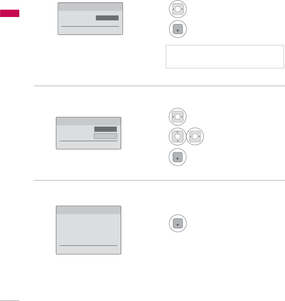
WATCHING TV / CHANNEL CONTROL
WATCHING TV / CHANNEL CONTROL
68
Step 4. Time Zone
Step 5. Auto Tuning
1Select Time Zone option.
2Select Daylight Saving
option.
3
ENTER
1
ENTER
Check your antenna connection and
start Auto Tuning.
6WHS7LPH=RQH
ᰙ3UHYLRXV ᯙ1H[W
7LPH=RQH ܁(DVWHUQ۽
'D\OLJKW6DYLQJ Auto
6WHS$XWR7XQLQJ
ᰙ3UHYLRXV ᯙ1H[W
%HIRUHVWDUWLQJ
EHVXUHWKDWWKH
79DQWHQQDLVFRQQHFWHG
Step 3. Power Indicator (For LED LCD TV)
1Select On or Off.
2
ENTER
6WHS3RZHU,QGLFDWRU
ᰙ3UHYLRXV ᯙ1H[W
6WDQGE\/LJKW ܁2II۽
ᯫ
This function is disable in “Step2. Mode
Setting - Store Demo”.