LG Electronics USA DT-CG Personal Computer User Manual DT final EN 2
LG Electronics USA Personal Computer DT final EN 2
Contents
- 1. Users Manual Part 1
- 2. Users Manual Part 2
Users Manual Part 2
23System Expansion
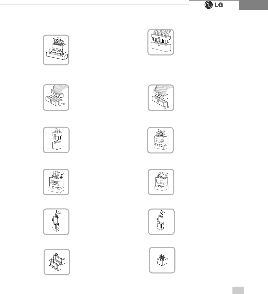
℘Power switch, power/ hard disk activity
LED connector (JFP1)
connects to the power
supply.
ℜPower connector(JPW1: 4 pins)
ℙPower connector (CONN1: 20 pins)
connects to the USB on
the front of the comput-
er.
ℝUSB connector(JUSB1: 10 pins)
JFP1
ATX1
JPW1 JUSB 1
,
connects to the IEEE
1394(6 pins) on the
front of the computer.
℞1394 connector
J1394
connects to the head-
phone and microphone
jacks on the front of the
computer.
℟Audio connector(JAUD1: 7 pins)
JAUD1
connects and supplies
power to the CPU fan.
℠CPU fan(C_FAN1: 3 pins)
CPU_FAN
If you are attaching only
one hard disk drive, be
sure to connect it to IDE1.
connects to the floppy
disk drive.
ℚHard disk/CD-ROM drive connectors
(IDE1, IDE2: 40 pins)
ℛFloppy disk drive connector(FDD1: 34
pins)
IDE1 IDE2 FDD1
connects and supplies
power to the system
fan at the bottom of the
computer.
℡System fan (S_FAN1: 3 pins)
SYSTEM_FAN
connects
6$7$GHYLFH
⌅
6$7$FRQQHFWRU
SATA
connects VFD.
⌆VFD connector
VFD
24 System Expansion
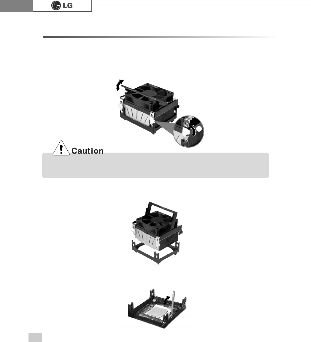
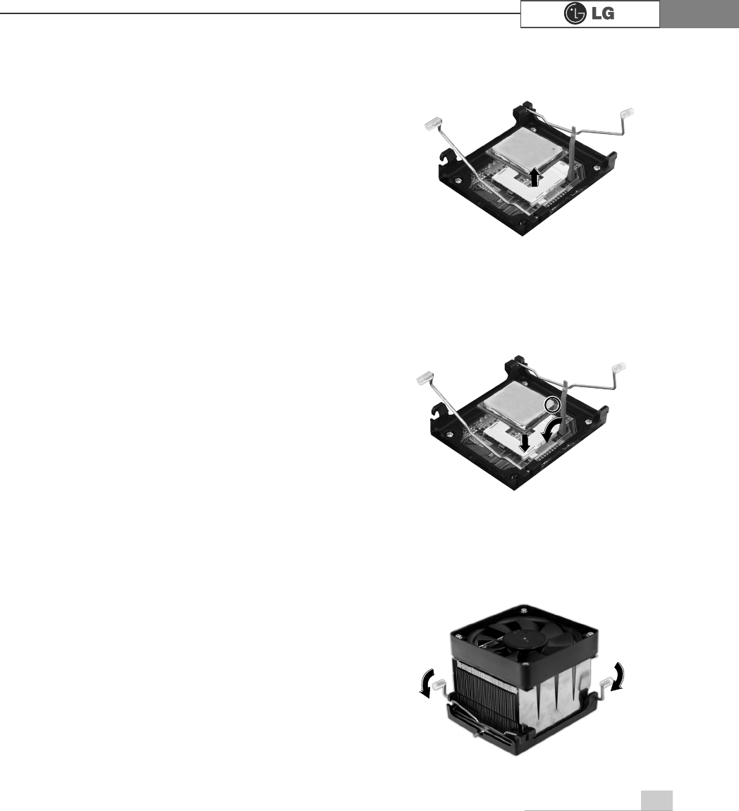
3-4 Replacing the CPU (CG/DG/CM/EG models)
The shape and replacement method of the CPU fan may be different depending on
the model.
1. Clamps on both sides of the CPU fasten the fan tightly to the CPU socket.
raise the handle(1) , release the clamps, and then spread them outward(2).
2. After releasing the clamps, lift and remove the CPU fan from the socket.
3. Raise the handle on the CPU socket to unlock the CPU.
℘
Consult your service representatives before replacing the CPU.
ℙ
25System Expansion
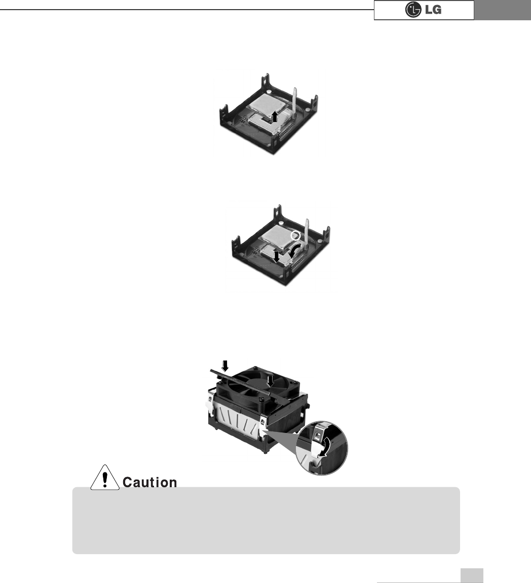
5.
Align the identifying marks at the corners of the new CPU and socket, and carefully
install the CPU in the socket. Lower the handle to lock the CPU in place.
6. Lift the clamps and slide them into the rails at the corners of the CPU socket, and
place the fan into the socket. Push down the handles to lock the clamps.
4. Lift the CPU straight up. Be careful not to damage the pins at the bottom of the CPU.
In some models, you can not lower one of the handles of the clamps all the way down.
For removing CPUs in these models, release the clamp on the other side first. For
installing CPUs in these models, lock this clamp first.
26 System Expansion
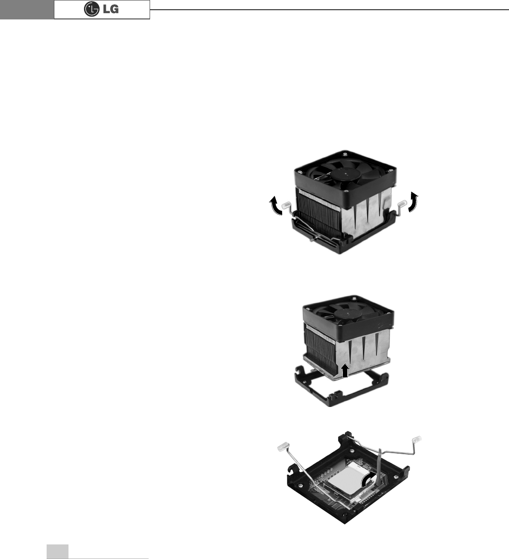
The shape and replacement method of the CPU fan may be different depending on
the model.
Replacing the CPU (FG model)
ⓞ5
elease the clamps as arrows indicate.
ⓟ
After releasing the clamps, lift and remove the CPU fan from the socket.
ⓠ
Raise the handle on the CPU socket to unlock the CPU.
27System Expansion
ⓡ
Gently lift the CPU straight up to remove.
ⓢ
Align the identifying marks at the corners of the new CPU and socket, and carefully
install the CPU in the socket. Lower the handle to lock the CPU in place.
ⓣ 3XVK
the clamps as arrows indicate.
28 System Expansion
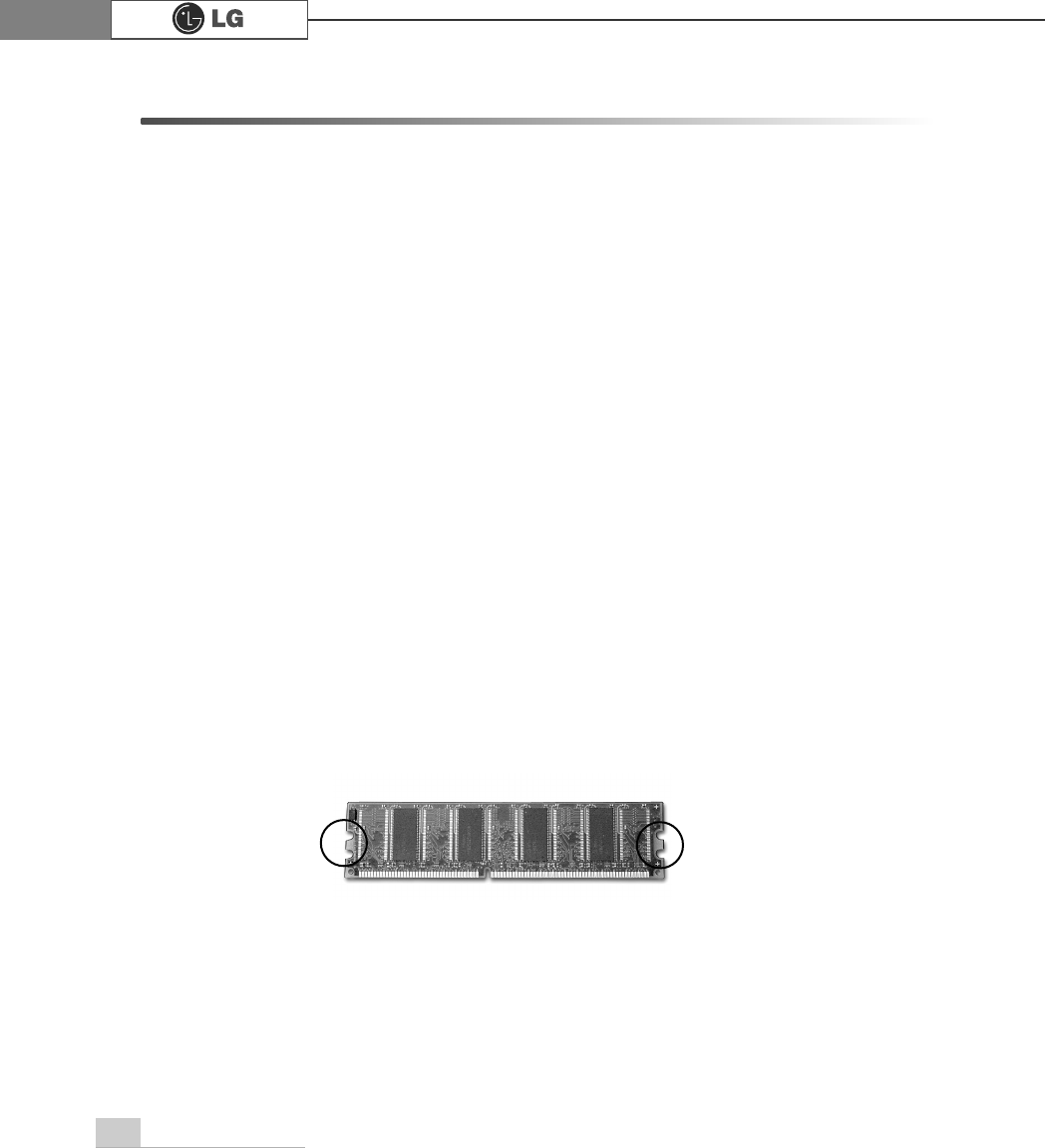
3-5. Increasing the memory
If you run out of memory while using the computer, you may want to increase the
amount of memory in your computer.
Note
Use a 2.5V DDR SDRAM DIMM.(The shape of the memory may be different depend-
ing on the model) DDR SDRAM enhances the rate of data transmission of the
SDRAM and looks different from SDRAM.
DDR
About memory
Your computer uses DDR(Double Data Rate) SDRAM DIMM(Dual In-Line Memory
Module) with 184 pins. Your computer supports Unbuffered DDR SDRAM DIMM of
128MB up to 1024MB in size in each socket, and 2048MB total.
Note: Windows 95, 98SE, ME supports memory up to 512MB total. Increasing the
memory beyond 512MB in these systems may cause errors while using the
computer.
Before increasing the memory
Static electricity can damage memory modules; be sure to minimize the static electric-
ity when replacing memory.
Make sure to replace the memory of the same type as the installed memory.
DIMM is different from SIMM in that it is configured for 64 bit operation; therefore,
your computer can operate with only one DIMM installed.
29System Expansion
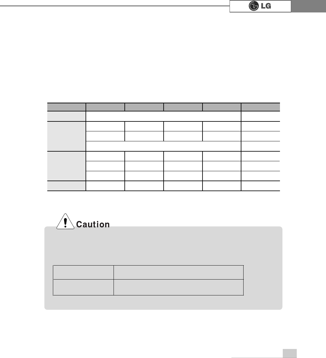
Purchasing a memory
Check the type of memory installed in your computer and refer to the memory configura-
tion chart before purchasing a memory.
Specification: PC2700/3200(184 pin DDR SDRAM DIMM)
Speed: 333MHz(166MHz X 2), 400MHz(200MHz X 2)
Size: 256MB, 512MB
Memory configuration chart
Total memory DIMM 1 DIMM 2 DIMM 3 DIMM 4 DUAL/SINGLE
SINGLE
DUAL
DUAL
SINGLE
DUAL
DUAL
DUAL
DUAL
512MB
256MB 256MB
256MB 256MB
256MB
1024MB
256MB 256MB 256MB 256MB
512MB 512MB
512MB 512MB
2048MB 512MB 512MB 512MB 512MB
512 (1/4)
256
Your computer supports PC2700/3200 DDR memory.
Use Unbuffered DDR SDRAM DIMM only to increase the memory.
FSB Frequency Supported memory type
533/800 MHz PC2700/3200-DDR SDRAM 333/400 MHz
30 System Expansion
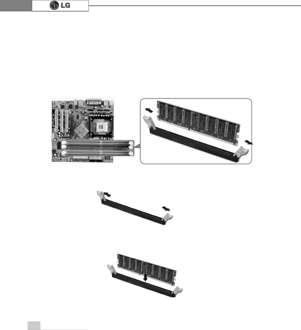
Replacing the memory
The main board configuration, memory socket, and the shape of memory may be dif-
ferent depending on the model.
1. Remove the screws on the real of the computer, and open the computer case.
1. Pull the latch on each side of a memory socket.
2. Align the notch at the bottom of the memory with a protrusion in the middle of the
socket, and then insert the memory straight down.
Note: Push the latch inward so that the memory is securely locked in the socket.
2. Pull the latch on each side of a memory socket to release the memory.
Installing a memory
Note: Before opening the case, turn off the computer and peripheral devices, and
remove the power cords.
31System Expansion
Checking the size of the installed memory
The computer automatically recognizes the newly installed memory; therefore, you do
not need to change the system setup. Follow the instruction below to check the size
of the installed memory.
1. Connect the power cord and other devices, and turn on the computer and monitor.
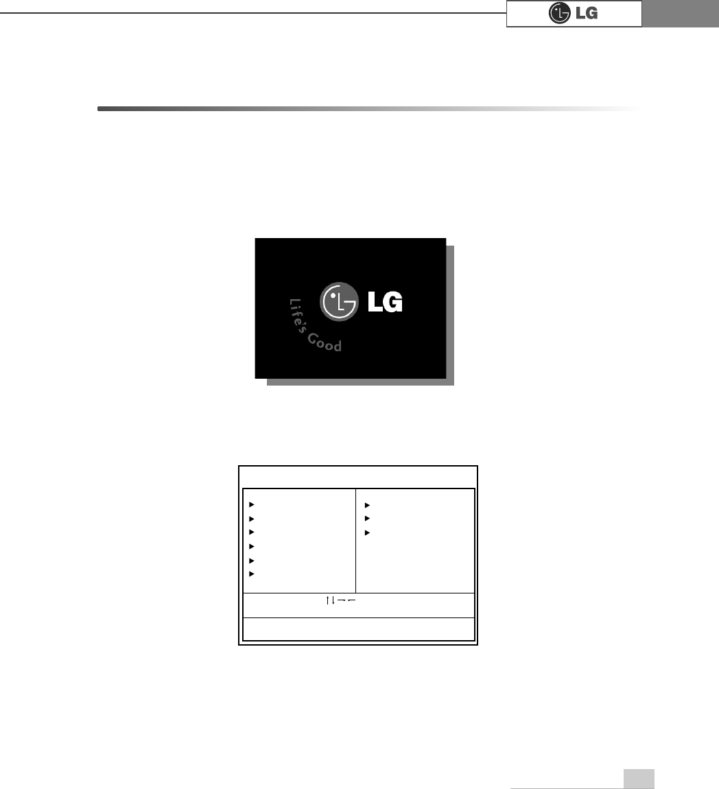
2. Press Delete when the following logo screen appears. In CMOS Setup Utility, select
Advanced BIOS Features. Change Full Screen Logo Show Selectable from Enabled to
Disabled. Press F10, and Enter to save the new setting.
3. The computer restarts. Press Esc at the logo screen shown above. If the following
screen appears, press Pause to stop and check the size of memory next to
Memory Testing.
4. Press Esc to continue the startup.
Press DEL to enter SETUP
$ZDUG0RGXODU%,26Y;;;;;$Q(QHUJ\6WDU$OO\
&RS\ULJKW&$ZDUG6RIWZDUH,QF
%XLOG,'/*;;;;;;;;;;;;;;
0DLQ3URFHVVRU,QWHO53HQWLXP5;3URFHVVRU;;;0+]
0HPRU\7HVW;;;;;;2.
3UHVV'(/WRHQWHU6(783
;;;;;;;;;;;;;;;;;;;;;;;;;
0HPRU\7HVWLQJ;;;;;;2.
To stop the logo screen for a moment,
press Delete key
⎀
Advanced
BIOS Features
⎀
Full Screen
Logo Show Selectable, and then
select Disable
Note:
32 System Expansion
3-6. Adding a hard disk drive
Your computer supports up to 4 E-IDE controllers and 2 hard disk drives.
Before adding a hard disk drive
Adding a hard disk drive
The following instruction describes the most typical configuration where your comput-
er already has a master hard disk drive and you are adding a slave hard disk drive.
Note: Check and write down the jumper settings, size, and number of cylinders,
heads, and sectors of the hard disk drive where you can refer to when you use
the system setup. (Some hard disk drives do not have the information written
on the drive)
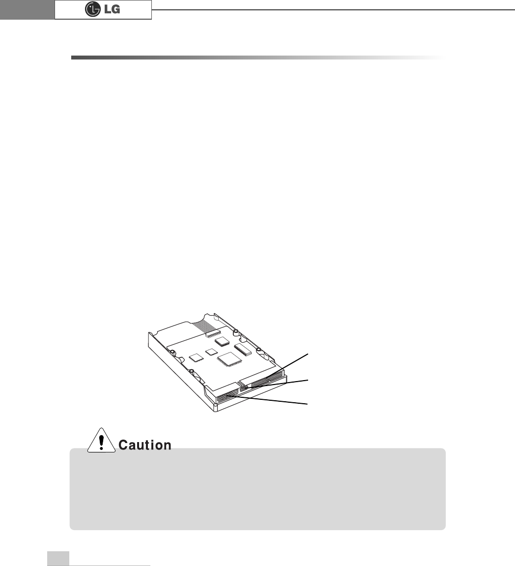
Note
Purchase an E-IDE hard disk drive.
Set the jumper setting to SL: Slave.
The jumper settings differ from one hard disk drive to another, so make sure you fol-
low the jumper setting information on top of the drive.
Jumper
Signal cable connector
Power connector
If the master hard drive is set to CS(Cable Select), the slave drive must also be
set to CS(Cable Select).
Using screws other than the ones provided with the hard disk drive can damage
the drive. Using longer or thicker screws can be fatal to the disk drive. A hard
disk drive must be mounted securely in order to provide reliable performance.
33System Expansion
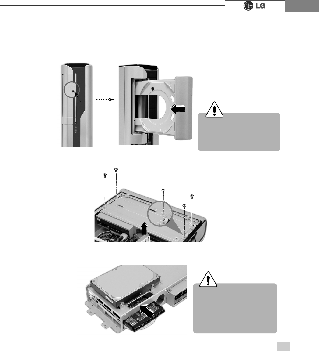
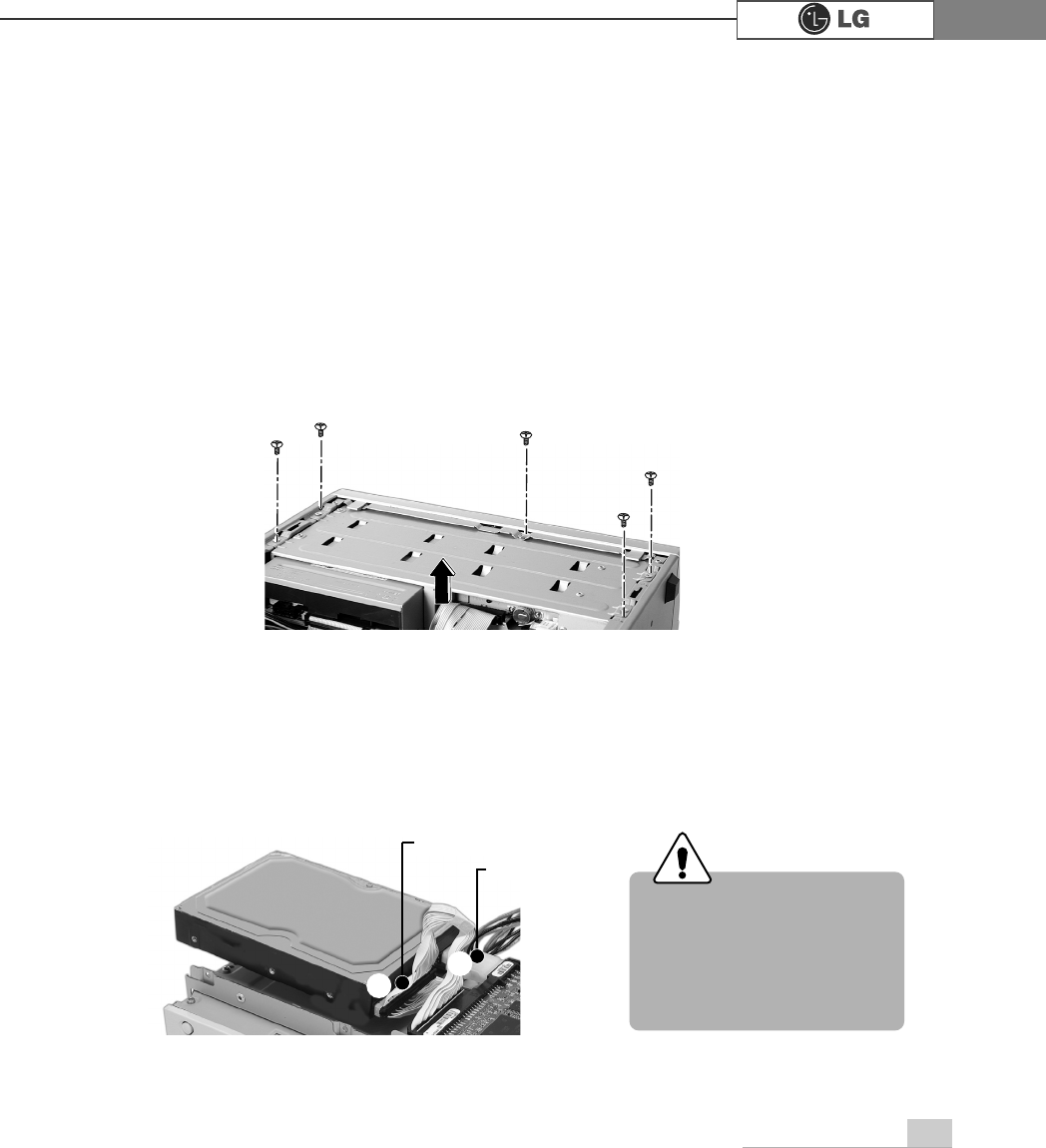
ⓟUse the screwdriver to remove the computer cover.
ⓞ
ⓞOpen the CD-ROM tray using a sharp pin 1...Remove the CD-ROM tray in the
direction of arrow 2.
ⓠGently push a new hard disk drive in the hard drive case as the direction of
arrow
Incorrect connection of the
power and signal cables to
a hard disk drive may dam-
age the drive and result in
drive malfunction or electric
shock.
Warning
℘ℙ
Turn off the computer before
remove power cable from your
computer. There is a risk of
electrical shock
Warning
Adding a hard disk drive (FG model)
34 System Expansion
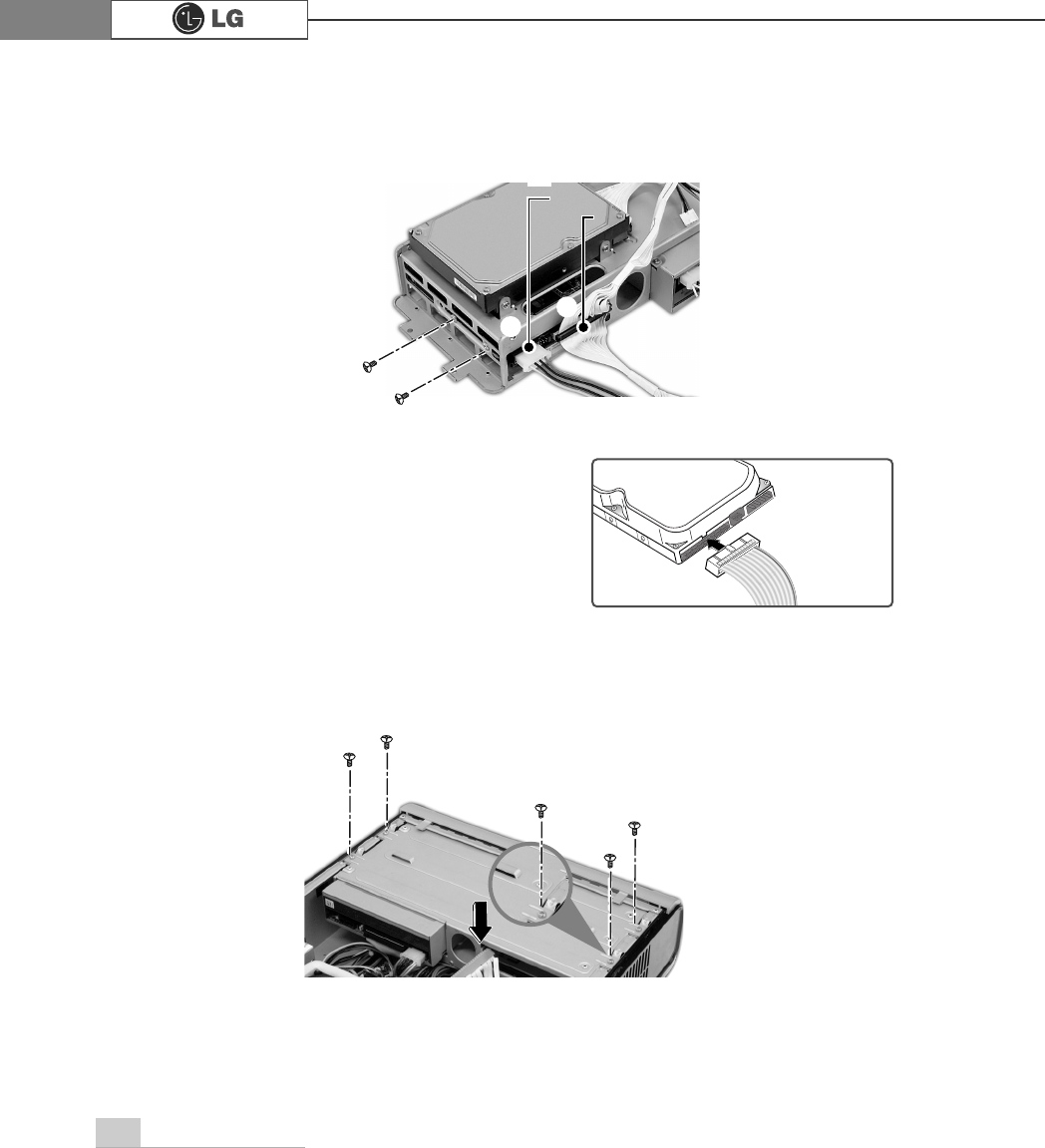
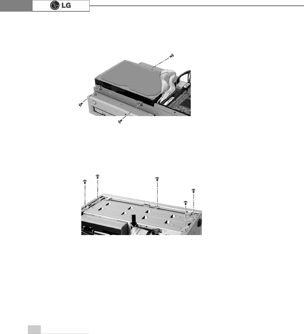
ⓡ
Connect a signal and power cable to the newly installed hard disk drive.
ⓢ
Install the hard disk drive case to the computer and tighten screws.
When connecting the signal cable to the hard
disk drive, be sure to align the tab in the mid-
dle of the cable with the notch on the connec-
tor of the hard disk drive. The notch and tab
prevent inserting the cable upside down.
Depending on the hard disk drive, the notch
may be at the bottom of the connector.
Note:
power cable
signal cable
℘ℙ
Note
You must setup and format the newly installed hard disk drive. Refer to Hard disk
drive setup.
35System Expansion
ⓞ
Refer to Opening the computer case to remove the computer case cover.
ⓠ
Connect a signal and power cable to the newly installed hard disk drive.
ⓟ
Remove screws on the hard drive case.
Adding a hard disk drive (CG/DG/CM models)
Incorrect connection of the
power and signal cables to
a hard disk drive may dam-
age the drive and result in
drive malfunction or electric
shock.
Warning
signal cable
power cable
ก
36 System Expansion
ⓣ
Refer to Closing the computer case to close the computer case cover
ⓢ
Tighten screws as shown o the picture
ⓡ
Install the hard disk drive case to the computer and tighten screws.
37System Expansion
Hard disk drive setup
1. Turn on the computer and monitor.
2. Press Delete key at the logo screen.
3. The CMOS Setup Utility opens.
4. Use arrow keys to select Standard CMOS Features, and press Enter.
Standard CMOS Features
Advanced BIOS Features
Advanced Chipset Features
Integrated Peripherals
Power Management Setup
PnP/PCI Configurations
ESC:Quit
F10:Save & Exit Setup
:Select Item
CMOS Setup Utility-Copyright(C) 1984-2001 Award Software
PC Health Status
Frequency/Voltage Control
Load Optimized Defaults
Set Password
Save & Exit Setup
Exit Without Saving
Virus Protection, Boot Sequence...
Press DEL to enter SETUP
38 System Expansion
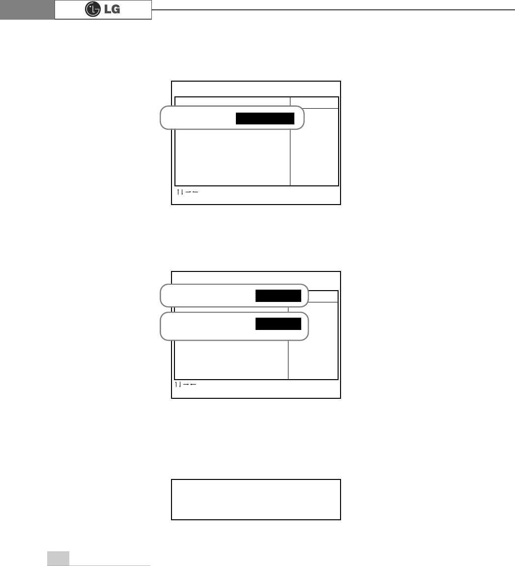
5. Use arrow keys to select IDE Primary Slave, and press Enter.
6. After setting IDE Primary Slave to Auto by pressing Enter, press Enter in IDE HDD
Auto-Detection so the system automatically recognizes the newly installed slave
hard disk drive.
7. Press F10 to save the new setting.
8. If the following message appears, press Enter. The computer restarts.
CMOS Setup Utility-Copyright(C) 1984-2001 Award Software
Standard CMOS Features
Date (mm:dd:yy) XX:XX:XX Item Help
Time (hh:mm:ss) XX:XX:XX
IDE Primary Slave Press Enter None Menu Level
Drive A XXXM, XXin To auto-detect the
Drive B None HDD’s size, head...
on this channel
Video EGA/VGA
Halt On Alt. But. Keyboard
Base Memory
Extended Memory
Total Memory
:Move Enter:Select +/-/PU/PD:Value F10:Save ESC:Exit
F1:Help F5:Previous Values F7:Optimized Defaults
CMOS Setup Utility-Copyright(C) 1984-2001 Award Software
Standard CMOS Features
IDE HDD Auto-Detection Press Enter Item Help
Menu Level
IDE Primary Slave Auto
Access Mode Auto To auto-detect the
HDD’s size, head...
Capacity XXXMB on this channel
Cylinder 0
Head X
Precomp X
Loading Zone X
Sector X
:Move Enter:Select +/-/PU/PD:Value F10:Save ESC:Exit
F1:Help F5:Previous Values F7:Optimized Defaults
IDE Primary Slave Press Enter None
Press Enter
IDE HDD Auto-Detection
IDE Primary Slave Auto
SAVE to CMOS and EXIT(Y/N)? Y
39System Expansion
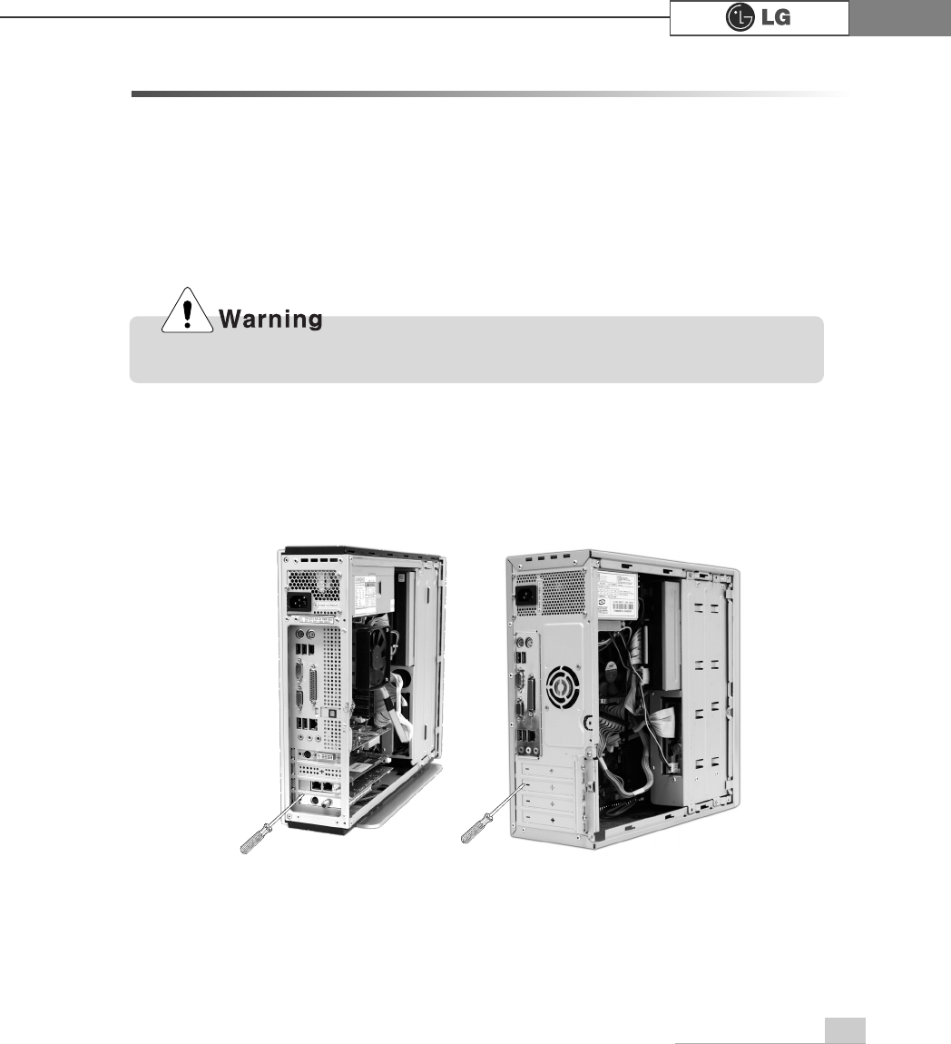
Installing expansion cards (FG/CG/CM/DG models)
When you are using the computer, you may need to install expansion cards to
improve funtionality. The following instruction describes how to install expansion
cards.
1. Refer to Opening the computer case to open the computer case cover.
2. Use a flat screwdriver to remove the metal cover for the expansion slot you are
about to use.(Remove only when you are adding a new expansion card)
CG/DG/CM
FG
Always use a screwdriver to open the case cover. There is the risk of injury.
40 System Expansion
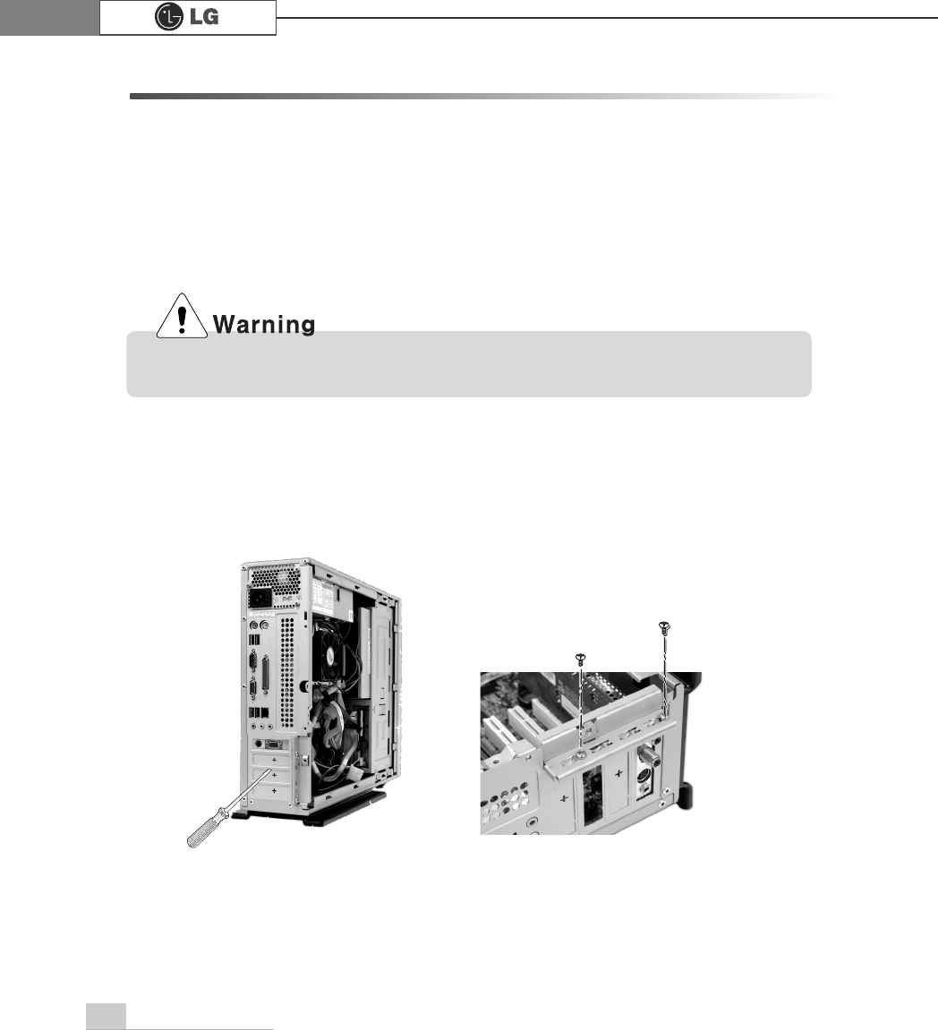
Installing expansion cards (EG model)
When you are using the computer, you may need to install expansion cards to
improve funtionality. The following instruction describes how to install expansion
cards.
1. Refer to Opening the computer case to open the computer case cover.
2. Use a screwdriver to remove the metal cover for the expansion slot you are about
to use.(Remove only when you are adding a new expansion card)
Use a screwdriver to remove the latch as shown on the right
Always use a screwdriver to open the case cover. There is the risk of injury.
Incorrect installation of an expansion card may damage the main board and
result in a computer malfunction.
41System Expansion
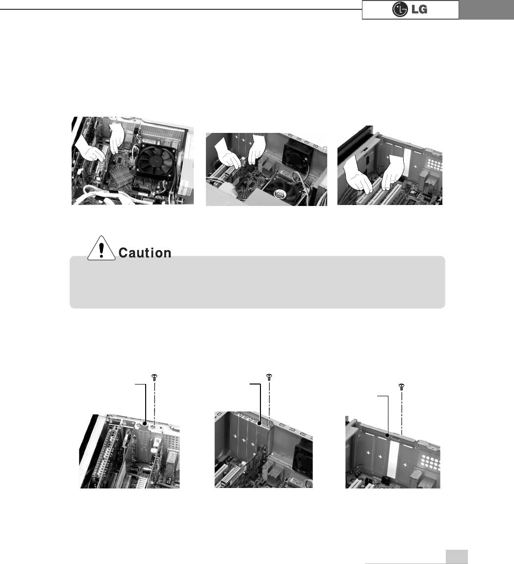
3. Hold the expansion card with both hands and align the expansion card and slot.
Push down evenly to insert the card into the slot.
4. Tighten a screw to fasten the metal bracket of the card to the computer case.
FG CG/DG/CM EG
FG CG/DG/CM EG
Installing expansion cards (Continued)
metal bracket metal bracket
metal bracket

42 System Expansion
5. Refer to Closing the computer case to close the case cover of the computer.
6. Install the driver program for the new expansion card.
Using the computer without closing the case may result in fire, electric shock,
injury, and/or damage to the computer.
CAUTION: Changes or modifications not expressly approved by the manufacturer
responsible for compliance could void the user’s authority to operate the equipment
WAR NING
This device complies with part 15 of the FCC Rules. Operation is subject to the
following two conditions: (1) This device may not cause harmful interference, and (2)
this device must accept any interference received, including interference that may cause
undesired operation.
INFORMATION TO USER:
This equipment has been tested and found to comply with the limit of a Class B digital
device, pursuant to Part 15 of the FCC Rules. These limits are designed to provide
reasonable protection against harmful interference in a residential installation. This
equipment generates, uses and can radiate radio frequency energy and, if not installed
and used in accordance with the instructions, may cause harmful interference to radio
communications. However, there is no guarantee that interference will not occur in a
particular installation; if this equipment does cause harmful interference to radio or
television reception, which can be determined by turning the equipment off and on, the
user is encouraged to try to correct the interference by one or more of the following
measures:
1. Reorient / Relocate the receiving antenna.
2. Increase the separation between the equipment and receiver.
3. Connect the equipment into an outlet on a circuit difference from that to which
the receiver is connected.
4. Consult the dealer or an experienced radio/TV technician for help

P/N: 3828BPH003A
Copyright 2004
LG Electronics, Inc., DigitalMate Co., Ltd.