LG Electronics USA DT-KG PERSONAL COMPUTER User Manual
LG Electronics USA PERSONAL COMPUTER Users Manual
UserManual.wiki
>
LG Electronics USA
>
DT-KG User Manual
>
USERS MANUAL 3
Contents
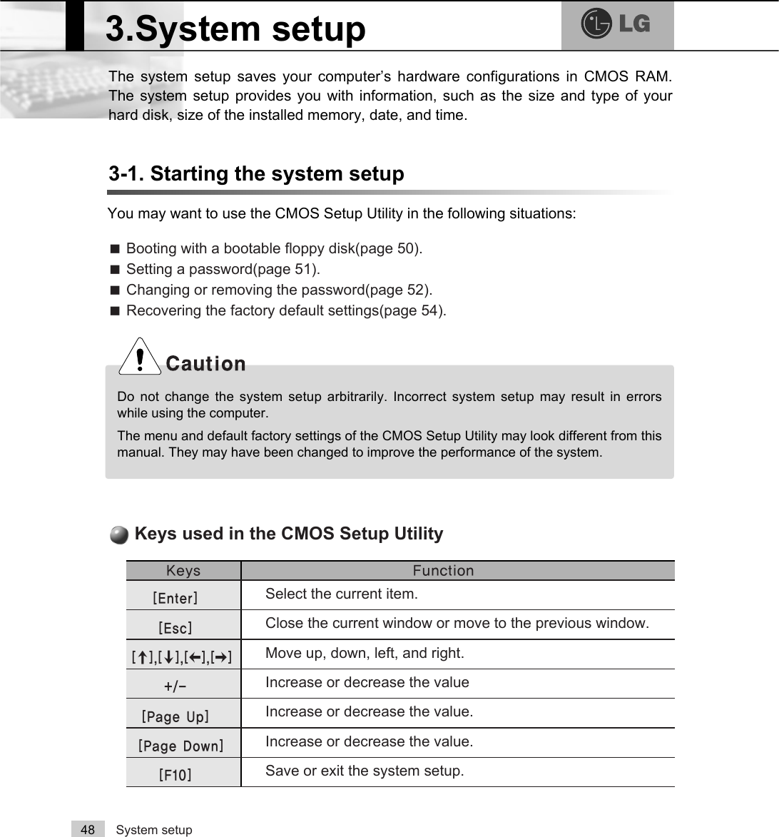
1.
USERS MANUAL 1
2.
USERS MANUAL 2
3.
USERS MANUAL 3
4.
USERS MANUAL 4
USERS MANUAL 3
Navigation menu
Upload a User Manual
Namespaces
Wiki Guide
HTML
PDF
Info
Views
User Manual
Discussion / Help
Navigation
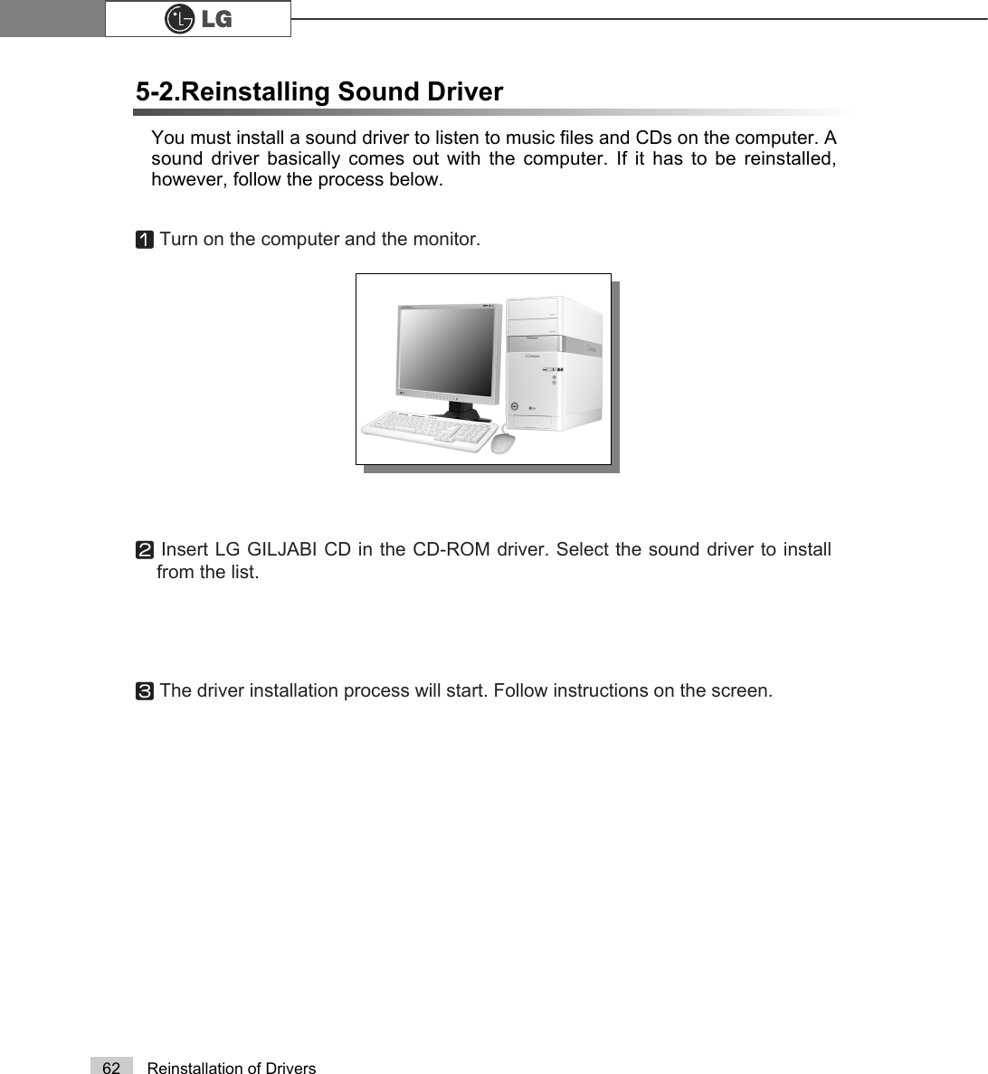
![45Using the systemⓞClick [Start]⍛[All programs]⍛[Norton Antivirus]⍛[Norton AntiVirus2005]. ⓟClick [Scan for virus] and select an item to scan.ⓠNorton AntiVirus is scanning virus.ⓡClick [Finish]. Virus scanning is complete.Running Norton AntivirusãIf any virus is detected, click[Fix] to repair.Note](https://usermanual.wiki/LG-Electronics-USA/DT-KG.USERS-MANUAL-3/User-Guide-519353-Page-1.png)
![System setup 49ⓞTurn on the computer and monitor.ⓟWhen LG logo appears on the screen, press [Delete].ⓠThe CMOS Setup Utility window appears.Phoenix-Award BIOS CMOS Setup UtilityĚStandard CMOS Features ĚPC Health StatusĚAdvanced BIOS Features ĚFrequency/Voltage ControlĚAdvanced Chipset Features Load Optimized Defaults ĚIntegrated Peripherals Set PasswordĚPower Management Setup Save & Exit SetupĚPnP/PCI Configurations Exit Without SavingEsc : Quit êëè é : Select ltemF10 : Save & Exit SetupTime, Date, Hard Disk Type.....ã 'LUHFWLRQ keys (arrow keys) move the cursor up, down,to the left and right. If Num Lock button is off, thearrow keys in the numeric keypad can be used justlike the cursor control keys.Note<Cursor keypad><Numeric keypad>](https://usermanual.wiki/LG-Electronics-USA/DT-KG.USERS-MANUAL-3/User-Guide-519353-Page-3.png)
![System setup503-2. Booting with a bootable floppy diskFollow the instruction below to set the floppy disk as start up disk.ⓞOpen the CMOS Setup Utility. Use the arrow keys to select Advanced BIOSFeatures and press [Enter].ⓠTo save changes in System Setup, press the [F10] key.ⓡWhen the following message appears, press [Enter]. The computer restarts.SAVE to CMOS and EXIT(Y/N)? Y Phoenix-Award BIOS CMOS Set up UtilityAdvanced BIOS FeatureVêëèé:Move Enter:Select +/-/PU/PD:Value F10:Save ESC:Exit F1:General HelpF5:Previous Values F7:Optimized DefaultsĚHard Disk Boot Priority Enabled BIOS Virus WarningDisabledHyper-Threding Technology EnabledQuick Boot Disabled 1st Boot Device CDROM2nd Boot Device Floppy3nd Boot Device HDD-0Boot Other Device EnabledSwap Floppy DisabledFloppy Seek DisabledBoot Up Num-Lock LED OnGate A20 Option FastSecurity Option SystemÁÁAPIC Function EnabledMPS Table Version 1.4Hard Disk S.M.A.R.T DisabledFull Screen LOGO Show DisabledSummary Screen Show EnabledItem HelpMemu Level ĚSelect Your Boot Device PriorityⓟUse >Ⓑ@>Ⓒ@>⒵@, and >Ⓐ@keys to select 1st Boot Device. Use page up/downkeys to select Floppy.1st Boot Device )ORSS\](https://usermanual.wiki/LG-Electronics-USA/DT-KG.USERS-MANUAL-3/User-Guide-519353-Page-4.png)
![51System setupⓟUse the arrow keys to select Security Option. Use the Page Up and PageDown keys to select Setup or System, and then press [Enter].ⓞStart the CMOS Setup Utility. Use the arrow keys to select Advanced BIOSFeatures, and then press [Enter].ⓠUse the arrow keys to select Set Password, and then press [Enter].3-3. Setting a passwordIf you want to protect the system setup from unauthorized users, follow theinstruction below to set a password.You can set a password in the CMOS Setup Utility program.If you forget the password, you cannot gain access to your system. Be sure to write downthe password in a safe place only you can refer to in case you forget the password.Phoenix-Award BIOS CMOS Set up UtilityAdvanced BIOS FeatureVêëèé:Move Enter:Select +/-/PU/PD:Value F10:Save ESC:Exit F1:General HelpF5:Previous Values F7:Optimized DefaultsĚHard Disk Boot Priority Enabled BIOS Virus WarningDisabledHyper-Threding Technology EnabledQuick Boot Disabled 1st Boot Device CDROM2nd Boot Device Floppy3nd Boot Device HDD-0Boot Other Device EnabledSwap Floppy DisabledFloppy Seek DisabledBoot Up Num-Lock LED OnGate A20 Option FastSecurity Option SystemÁÁAPIC Function EnabledMPS Table Version 1.4Hard Disk S.M.A.R.T DisabledFull Screen LOGO Show DisabledSummary Screen Show EnabledItem HelpMemu Level ĚSelect Your Boot Device Priority6HWXSSecurity OptionãIf you select Setup in the Security Option, the computer asks for a password next timeyou try to enter the CMOS Setup Utility. If you select System, the computer asks for apassword next time you start the computer and also when you try to enter the CMOSSetup Utility. Setting the System password prevents unauthorized users from using thecomputer or changing the system setup.Note](https://usermanual.wiki/LG-Electronics-USA/DT-KG.USERS-MANUAL-3/User-Guide-519353-Page-5.png)
![52 System setup3-4. Changing or removing the passwordYou must know the password to change or remove it.ⓞStart the CMOS Setup Utility, enter your password, and then press [Enter].ⓢIf the following message appears, enter the password again, and then press [Enter].ⓣPress [F10] to save the new settings.ⓤIf the following message appears, press [Enter]. The computer restarts.ⓡIf the following message appears, enter the new password and then press[Enter]. A password must consist of characters A~Z and numbers 0~9, and hasthe maximum length of 8.SAVE to CMOS and EXIT(Y/N)? Y Confirm Password : Enter Password :Phoenix-Award BIOS CMOS Setup UtilityĚStandard CMOS Features ĚPC Health StatusĚAdvanced BIOS Features ĚFrequency/Voltage ControlĚAdvanced Chipset Features Load Optimized Defaults ĚIntegrated Peripherals Set PasswordĚPower Management Setup Save & Exit SetupĚPnP/PCI Configurations Exit Without SavingEsc : Quit êëè é : Select ltemF10 : Save & Exit SetupChange/Set/Disable/PasswordEnter Password:](https://usermanual.wiki/LG-Electronics-USA/DT-KG.USERS-MANUAL-3/User-Guide-519353-Page-6.png)
![53System setupãTo change the password, follow the instructions on Setting a password.ãTo remove the password, follow the instructions below.ⓟUse arrow keys to select Set Password, and then press [Enter].ⓠIf the following message appears, press [Enter].ⓡIf the following message appears, press [Enter].ⓢPress [F10] to save the new setting.ⓣIf the following message appears, press [Y] key and [Enter]. The computerrestarts.PASSWORD DISABLD!!!Press any key to continue...Enter Password : SAVE to CMOS and EXIT(Y/N)? Y Phoenix-Award BIOS CMOS Setup UtilityĚStandard CMOS Features ĚPC Health StatusĚAdvanced BIOS Features ĚFrequency/Voltage ControlĚAdvanced Chipset Features Load Optimized Defaults ĚIntegrated Peripherals Set PasswordĚPower Management Setup Save & Exit SetupĚPnP/PCI Configurations Exit Without SavingEsc : Quit êëè é : Select ltemF10 : Save & Exit SetupChange/Set/Disable/PasswordSet Password](https://usermanual.wiki/LG-Electronics-USA/DT-KG.USERS-MANUAL-3/User-Guide-519353-Page-7.png)
![54 System setup3-5. Recovering the factory default settingsYou can follow the instructions below to recover the factory default settings.ⓞStart the CMOS Setup Utility. Use the arrow keys to select Load OptimizedDefaults and press [Enter].ⓟIf the following message appears, press [Y] key and then [Enter]. The factorydefault settings have been recovered.ⓠTo save changes in System Setup, press the [F10] key.ⓡIf the following message appears, press [Enter]. The computer restarts.SAVE to CMOS and EXIT(Y/N)? Y Load Optimized Defaults (Y/N) ? Y](https://usermanual.wiki/LG-Electronics-USA/DT-KG.USERS-MANUAL-3/User-Guide-519353-Page-8.png)
![55System setupYou can use power saving function in Windows OS no matter how you set theBIOS setup.3-6. Using Power saving functionⓡClick [Advanced] for setup if necessary and then click [OK].ⓠSet the Power option properties and click [OK].ⓞClick [Start]èè[Control panel]è[Switch to classic view].ⓟDouble click Power option icon from the control panel.ãHibernation mode: It saves dataand turns off the power and thenrestores data when the systemstarts again.NoteThere are some devices whichdo not support the power savingfunction properly. If you haveinstalled such devices, youshould disable power savingfunction.](https://usermanual.wiki/LG-Electronics-USA/DT-KG.USERS-MANUAL-3/User-Guide-519353-Page-9.png)
![56 System setupYour computer support ACPI power saving and you can change Sleep State inthe BIOS system setup. Set to S3(STR) to manage power more effectively instandby mode. Use the power button to exit standby mode. If you want to use akeyboard stroke or mouse movement to exit standby mode, change S3(STR) toS1(POS).Note: S1(Power On Suspend), S3(Save to Ram)ⓞStart the CMOS Setup Utility. Use the arrow keys to select Power ManagementSetup and then press [Enter].ⓟUse the arrow keys to select Sleep State, and PageUp and PageDown keys toset S1(POS).ⓠTo save changes in System Setup, press the [F10] key.ⓡIf the following message appears, press [Enter].The computer restarts.SAVE to CMOS and EXIT(Y/N)? Y Phoenix-Award BIOS CMOS Set up UtilityPower Management Setupêëèé:Move Enter:Select +/-/PU/PD:Value F10:Save ESC:Exit F1:General HelpF5:Previous Values F7:Optimized DefaultsSleep State [S1/(POS)]ÁRun VGA BIOS If S3 Resume [Auto]Power Management [User Define]Video Off Method [DPMS]Video Off In Suspend [YES]Suspend Type [Stop Grant]MODEM Use IRQ [3]Suspend Mode [Disabled]HDD Power Down [Disabled]Power Button Function [Suspend]CPU THRM-Throtting [**.*%]Wake Up On PME [Disabled]ÁUSB KB Wake-Up From S3 DisabledResume by Alarm [Disabled]ÁDate(of Month) Alarm 0ÁTime(hh:mm:ss) Alarm 0:0:0Item HelpMemu Level ĚS1 (POS)Sleep State](https://usermanual.wiki/LG-Electronics-USA/DT-KG.USERS-MANUAL-3/User-Guide-519353-Page-10.png)

![System Recovery56You can restore the system in two ways depending on the current status of the sys-tem. However, to restore the hard disk, you need to back up necessary softwareand data files in advance. After completing Windows installation, you need to regis-ter the User Properties when booting the system as if you did your new computer.4.System RecoveryⓞBack up the data stored in the computer.ⓟInsert the Restore CD in the CD-ROM drive. When "Press any key to bootfrom CD..." message appears on the screen, press the [Enter] key. ⓠContinue installation by following instructions on the screen. ⓡAfter completing installation of Windows, remove the CD and restart the sys-tem. When the following screen appears, register the User Properties accordingto instructions on the screen. Installation with Recovery CDInstallationⓢAfter the Windows operating system installation is complete, install the LG GILJABICD (software installation CD) on your computer, and then you can use all applicationprograms and device drivers.](https://usermanual.wiki/LG-Electronics-USA/DT-KG.USERS-MANUAL-3/User-Guide-519353-Page-12.png)
![System Recovery 57For Windows usersIf Windows XP is already installed on the hard disk, you can upgrade existingWindows XP without formatting the hard diskIn the case that Windows XP is already running on the hard disk, upgradeWindows XP as follows.ⓟClick the [Start] and [Run] button.ⓠInsert the Restore CD, and input D:\i386\winnt32.exe/unattend. Then, click the[OK] button. (When the CD-ROM drive is D drive.)ⓞTurn on the system where Windows XP is installed.Installation of Windows XP UpgradeãTo execute "winnt32.exe" without using"Unattend" option, you must input theproduct key attached on the computer.You also need to have the computercertified within 30 days after thisNote](https://usermanual.wiki/LG-Electronics-USA/DT-KG.USERS-MANUAL-3/User-Guide-519353-Page-13.png)
![5. Reinstallation of Drivers58 Reinstallation of DriversYou must install the printer driver after connecting the printer. Windows XP canautomatically detect printer drivers. However, if Windows XP does not detect yourprinter driver, install the printer driver as follows.5-1.Reinstalling Printer DriverⓟDouble click the [Printer and Fax] on the Control Panel window.ⓠWhen the following screen appears, click the [Add Printer] button.ⓞSelect [Start] èè[Control Panel] è[Class Desktop].ⓡWhen the Add Printer Wizard appears, click the [Next] button.](https://usermanual.wiki/LG-Electronics-USA/DT-KG.USERS-MANUAL-3/User-Guide-519353-Page-14.png)
![59Reinstallation of DriversⓢWhen the following screen appears, check the connection type of the printer -local or network. Then, select a printer and click the [Next] button.ⓣNew Printer Detection screen will appear. Click the [Next] button.ⓤWhen Set Printer Port screen appears, select LPT1 or LPT2 before clicking the[Next] button.ⓥSelect the manufacturer and model of your printer on the Select Printer screen.If your printer came with an installation disk, click [Have Disk]. If not, just clickthe [Next] button.](https://usermanual.wiki/LG-Electronics-USA/DT-KG.USERS-MANUAL-3/User-Guide-519353-Page-15.png)
![60 Reinstallation of DriversⓧWhen Print Test Page screen appears, click the [Yes] and [Next].ⓦInsert the diskette or driver CD in the driver and click the [OK] button.ⓦName the printer, and click the [Next] button.When [Have Disk] is selected.When [Next] is selected](https://usermanual.wiki/LG-Electronics-USA/DT-KG.USERS-MANUAL-3/User-Guide-519353-Page-16.png)
![61Reinstallation of DriversⓨAfter the test page is properly printed out, click the [OK] button. ⓩWhen the following screen appears, check the printer and click the [Finish]button.⓪Now, the printer has been added. .](https://usermanual.wiki/LG-Electronics-USA/DT-KG.USERS-MANUAL-3/User-Guide-519353-Page-17.png)