LG Electronics USA DT-KG PERSONAL COMPUTER User Manual
LG Electronics USA PERSONAL COMPUTER Users Manual
Contents
- 1. USERS MANUAL 1
- 2. USERS MANUAL 2
- 3. USERS MANUAL 3
- 4. USERS MANUAL 4
USERS MANUAL 3
45Using the system
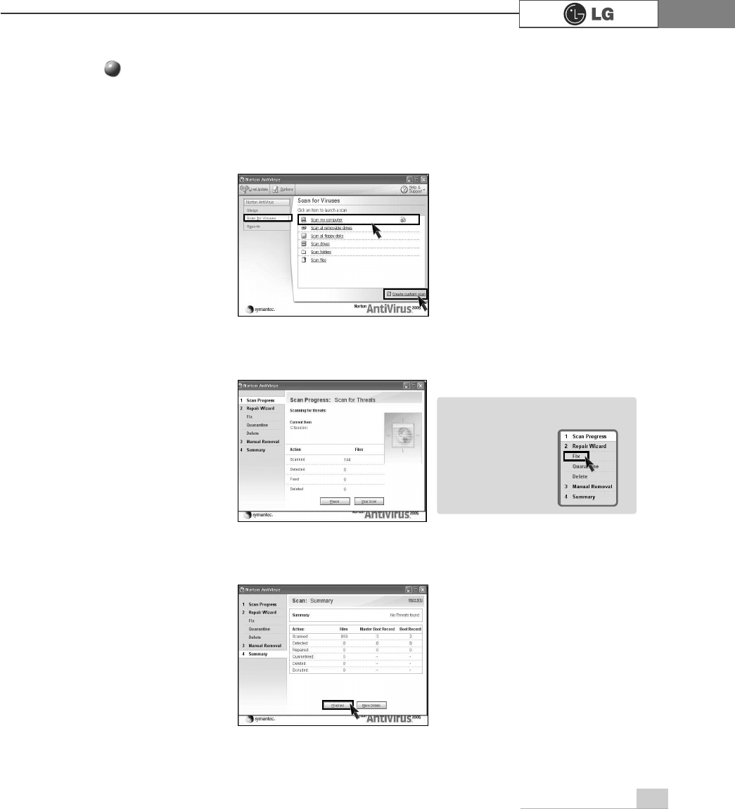
ⓞClick [Start]⍛[All programs]⍛[Norton Antivirus]⍛[Norton AntiVirus2005].
ⓟClick [Scan for virus] and select an item to scan.
ⓠNorton AntiVirus is scanning virus.
ⓡClick [Finish]. Virus scanning is complete.
Running Norton Antivirus
ãIf any virus is detected, click
[Fix] to repair.
Note
System setup
48
The system setup saves your computer’s hardware configurations in CMOS RAM.
The system setup provides you with information, such as the size and type of your
hard disk, size of the installed memory, date, and time.
3-1. Starting the system setup
You may want to use the CMOS Setup Utility in the following situations:
ãBooting with a bootable floppy disk(page 50).
ãSetting a password(page 51).
ãChanging or removing the password(page 52).
ãRecovering the factory default settings(page 54).
Do not change the system setup arbitrarily. Incorrect system setup may result in errors
while using the computer.
The menu and default factory settings of the CMOS Setup Utility may look different from this
manual. They may have been changed to improve the performance of the system.
.H\V )XQFWLRQ
Select the current item.
>(QWHU@
Close the current window or move to the previous window.
>(VF@
Move up, down, left, and right.
>Ⓑ@>Ⓒ@>⒵@>Ⓐ@
Increase or decrease the value
Increase or decrease the value.
Increase or decrease the value.
Save or exit the system setup.
>3DJH8S@
>3DJH'RZQ@
>)@
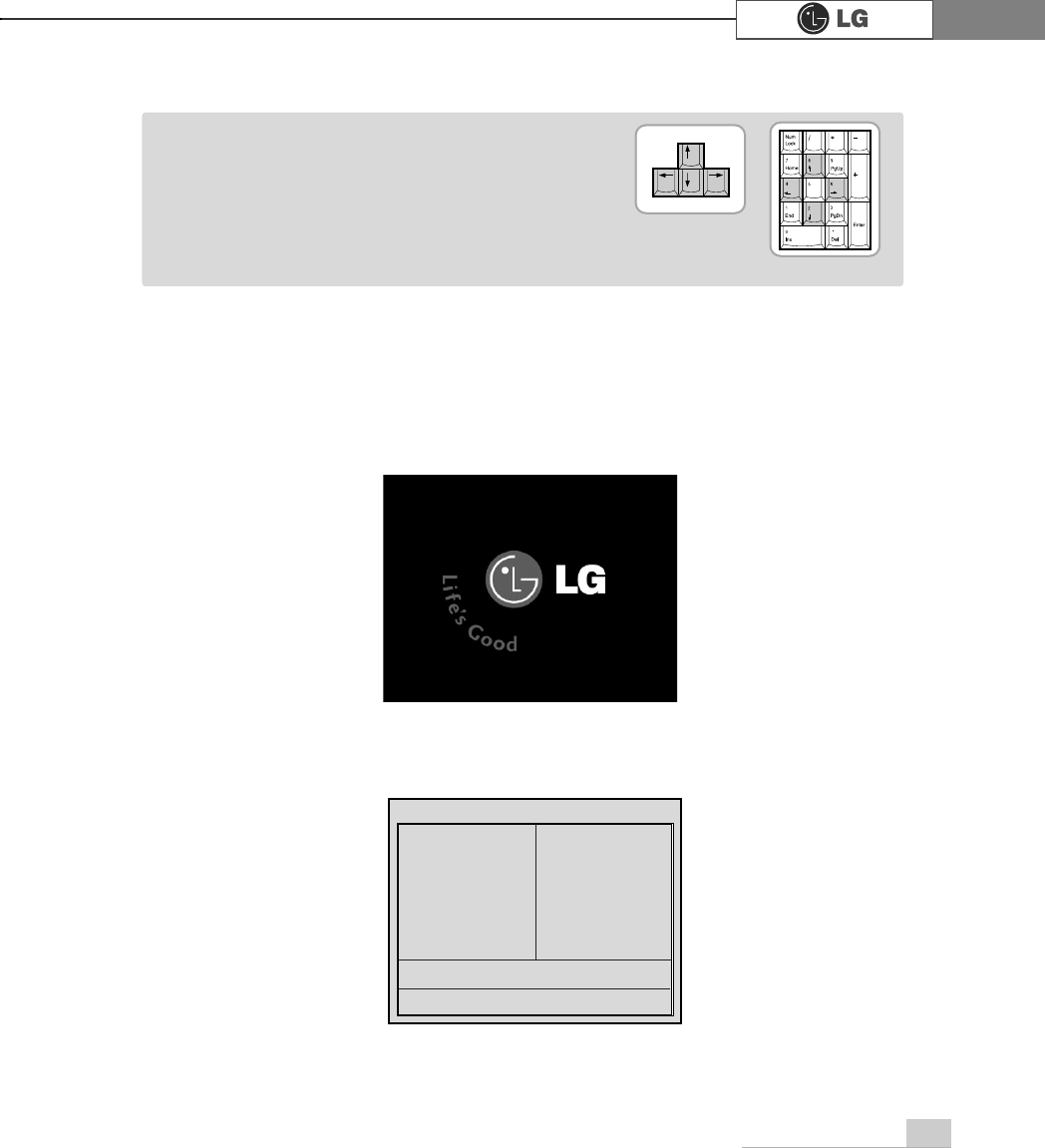
Keys used in the CMOS Setup Utility
3.System setup
System setup 49
ⓞ
Turn on the computer and monitor.
ⓟ
When LG logo appears on the screen, press [Delete].
ⓠ
The CMOS Setup Utility window appears.
Phoenix-Award BIOS CMOS Setup Utility
ĚStandard CMOS Features Ě
PC Health Status
ĚAdvanced BIOS Features ĚFrequency/Voltage Control
ĚAdvanced Chipset Features Load Optimized Defaults
ĚIntegrated Peripherals Set Password
ĚPower Management Setup Save & Exit Setup
ĚPnP/PCI Configurations Exit Without Saving
Esc : Quit êëè é : Select ltem
F10 : Save & Exit Setup
Time, Date, Hard Disk Type.....
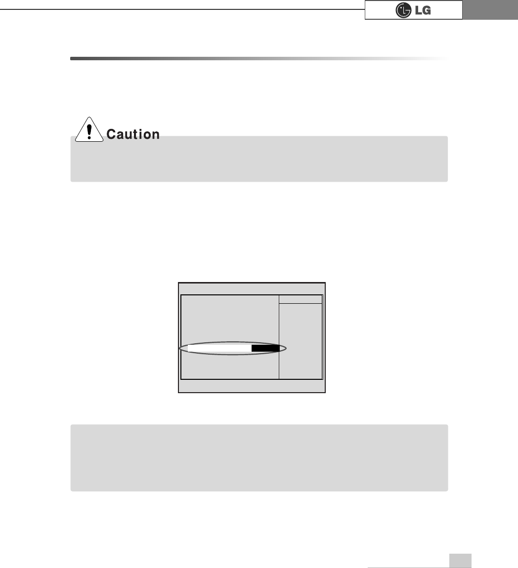
ã 'LUHFWLRQ keys (arrow keys) move the cursor up, down,
to the left and right. If Num Lock button is off, the
arrow keys in the numeric keypad can be used just
like the cursor control keys.
Note
<Cursor keypad>
<Numeric keypad>
System setup50
3-2. Booting with a bootable floppy disk
Follow the instruction below to set the floppy disk as start up disk.
ⓞ
Open the CMOS Setup Utility. Use the arrow keys to select Advanced BIOS
Features and press [Enter].
ⓠ
To save changes in System Setup, press the [F10] key.
ⓡ
When the following message appears, press [Enter]. The computer restarts.
SAVE to CMOS and EXIT(Y/N)? Y
Phoenix-Award BIOS CMOS Set up Utility
Advanced BIOS Feature
V
êëèé:Move Enter:Select +/-/PU/PD:Value F10:Save ESC:Exit F1:General Help
F5:Previous Values F7:Optimized Defaults
Ě
Hard Disk Boot Priority Enabled
BIOS Virus Warning
Disabled
Hyper-Threding Technology Enabled
Quick Boot Disabled
1st Boot Device CDROM
2nd Boot Device Floppy
3nd Boot Device HDD-0
Boot Other Device Enabled
Swap Floppy Disabled
Floppy Seek Disabled
Boot Up Num-Lock LED On
Gate A20 Option Fast
Security Option System
Á
ÁAPIC Function Enabled
MPS Table Version 1.4
Hard Disk S.M.A.R.T Disabled
Full Screen LOGO Show Disabled
Summary Screen Show Enabled
Item Help
Memu Level Ě
Select Your Boot
Device Priority
ⓟUse
>Ⓑ@>Ⓒ@>⒵@
, and
>Ⓐ@
keys to select 1st Boot Device. Use page up/down
keys to select Floppy.
1st Boot Device
)ORSS\
51System setup
ⓟ
Use the arrow keys to select Security Option. Use the Page Up and Page
Down keys to select Setup or System, and then press [Enter].
ⓞ
Start the CMOS Setup Utility. Use the arrow keys to select Advanced BIOS
Features, and then press [Enter].
ⓠ
Use the arrow keys to select Set Password, and then press [Enter].
3-3. Setting a password
If you want to protect the system setup from unauthorized users, follow the
instruction below to set a password.
You can set a password in the CMOS Setup Utility program.
If you forget the password, you cannot gain access to your system. Be sure to write down
the password in a safe place only you can refer to in case you forget the password.
Phoenix-Award BIOS CMOS Set up Utility
Advanced BIOS Feature
V
êëèé:Move Enter:Select +/-/PU/PD:Value F10:Save ESC:Exit F1:General Help
F5:Previous Values F7:Optimized Defaults
Ě
Hard Disk Boot Priority Enabled
BIOS Virus Warning
Disabled
Hyper-Threding Technology Enabled
Quick Boot Disabled
1st Boot Device CDROM
2nd Boot Device Floppy
3nd Boot Device HDD-0
Boot Other Device Enabled
Swap Floppy Disabled
Floppy Seek Disabled
Boot Up Num-Lock LED On
Gate A20 Option Fast
Security Option System
Á
ÁAPIC Function Enabled
MPS Table Version 1.4
Hard Disk S.M.A.R.T Disabled
Full Screen LOGO Show Disabled
Summary Screen Show Enabled
Item Help
Memu Level Ě
Select Your Boot
Device Priority
6HWXS
Security Option
ãIf you select Setup in the Security Option, the computer asks for a password next time
you try to enter the CMOS Setup Utility. If you select System, the computer asks for a
password next time you start the computer and also when you try to enter the CMOS
Setup Utility. Setting the System password prevents unauthorized users from using the
computer or changing the system setup.
Note
52 System setup
3-4. Changing or removing the password
You must know the password to change or remove it.
ⓞ
Start the CMOS Setup Utility, enter your password, and then press [Enter].
ⓢ
If the following message appears, enter the password again, and then press [Enter].
ⓣ
Press [F10] to save the new settings.
ⓤ
If the following message appears, press [Enter]. The computer restarts.
ⓡ
If the following message appears, enter the new password and then press
[Enter]. A password must consist of characters A~Z and numbers 0~9, and has
the maximum length of 8.
SAVE to CMOS and EXIT(Y/N)? Y
Confirm Password :
Enter Password :
Phoenix-Award BIOS CMOS Setup Utility
ĚStandard CMOS Features Ě
PC Health Status
ĚAdvanced BIOS Features ĚFrequency/Voltage Control
ĚAdvanced Chipset Features Load Optimized Defaults
ĚIntegrated Peripherals Set Password
ĚPower Management Setup Save & Exit Setup
ĚPnP/PCI Configurations Exit Without Saving
Esc : Quit êëè é : Select ltem
F10 : Save & Exit Setup
Change/Set/Disable/Password
Enter Password:
53System setup
ãTo change the password, follow the instructions on Setting a password.
ãTo remove the password, follow the instructions below.
ⓟ
Use arrow keys to select Set Password, and then press [Enter].
ⓠ
If the following message appears, press [Enter].
ⓡ
If the following message appears, press [Enter].
ⓢ
Press [F10] to save the new setting.
ⓣ
If the following message appears, press [Y] key and [Enter]. The computer
restarts.
PASSWORD DISABLD!!!
Press any key to continue...
Enter Password :
SAVE to CMOS and EXIT(Y/N)? Y
Phoenix-Award BIOS CMOS Setup Utility
ĚStandard CMOS Features Ě
PC Health Status
ĚAdvanced BIOS Features ĚFrequency/Voltage Control
ĚAdvanced Chipset Features Load Optimized Defaults
ĚIntegrated Peripherals Set Password
ĚPower Management Setup Save & Exit Setup
ĚPnP/PCI Configurations Exit Without Saving
Esc : Quit êëè é : Select ltem
F10 : Save & Exit Setup
Change/Set/Disable/Password
Set Password

54 System setup
3-5. Recovering the factory default settings
You can follow the instructions below to recover the factory default settings.
ⓞ
Start the CMOS Setup Utility. Use the arrow keys to select Load Optimized
Defaults and press [Enter].
ⓟ
If the following message appears, press [Y] key and then [Enter]. The factory
default settings have been recovered.
ⓠ
To save changes in System Setup, press the [F10] key.
ⓡ
If the following message appears, press [Enter]. The computer restarts.
SAVE to CMOS and EXIT(Y/N)? Y
Load Optimized Defaults (Y/N) ? Y
55System setup
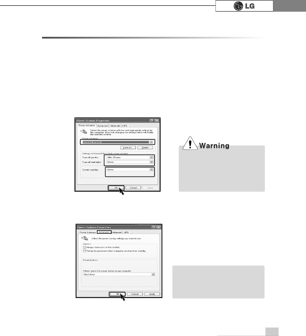
You can use power saving function in Windows OS no matter how you set the
BIOS setup.
3-6. Using Power saving function
ⓡClick [Advanced] for setup if necessary and then click [OK].
ⓠSet the Power option properties and click [OK].
ⓞClick [Start]è
è[Control panel]è[Switch to classic view].
ⓟDouble click Power option icon from the control panel.
ãHibernation mode: It saves data
and turns off the power and then
restores data when the system
starts again.
Note
There are some devices which
do not support the power saving
function properly. If you have
installed such devices, you
should disable power saving
function.
56 System setup
Your computer support ACPI power saving and you can change Sleep State in
the BIOS system setup. Set to S3(STR) to manage power more effectively in
standby mode. Use the power button to exit standby mode. If you want to use a
keyboard stroke or mouse movement to exit standby mode, change S3(STR) to
S1(POS).
Note: S1(Power On Suspend), S3(Save to Ram)
ⓞ
Start the CMOS Setup Utility. Use the arrow keys to select Power Management
Setup and then press [Enter].
ⓟ
Use the arrow keys to select Sleep State, and PageUp and PageDown keys to
set S1(POS).
ⓠ
To save changes in System Setup, press the [F10] key.
ⓡ
If the following message appears, press [Enter].The computer restarts.
SAVE to CMOS and EXIT(Y/N)? Y
Phoenix-Award BIOS CMOS Set up Utility
Power Management Setup
êëèé:Move Enter:Select +/-/PU/PD:Value F10:Save ESC:Exit F1:General Help
F5:Previous Values F7:Optimized Defaults
Sleep State [S1/(POS)]
ÁRun VGA BIOS If S3 Resume [Auto]
Power Management [User Define]
Video Off Method [DPMS]
Video Off In Suspend [YES]
Suspend Type [Stop Grant]
MODEM Use IRQ [3]
Suspend Mode [Disabled]
HDD Power Down [Disabled]
Power Button Function [Suspend]
CPU THRM-Throtting [**.*%]
Wake Up On PME [Disabled]
ÁUSB KB Wake-Up From S3 Disabled
Resume by Alarm [Disabled]
ÁDate(of Month) Alarm 0
ÁTime(hh:mm:ss) Alarm 0:0:0
Item Help
Memu Level Ě
S1 (POS)
Sleep State

57memo
PHPR
System Recovery
56
You can restore the system in two ways depending on the current status of the sys-
tem. However, to restore the hard disk, you need to back up necessary software
and data files in advance. After completing Windows installation, you need to regis-
ter the User Properties when booting the system as if you did your new computer.
4.System Recovery
ⓞ
Back up the data stored in the computer.
ⓟInsert the Restore CD in the CD-ROM drive. When "Press any key to boot
from CD..." message appears on the screen, press the [Enter] key.
ⓠContinue installation by following instructions on the screen.
ⓡAfter completing installation of Windows, remove the CD and restart the sys-
tem. When the following screen appears, register the User Properties according
to instructions on the screen.
Installation with Recovery CD
Installation
ⓢAfter the Windows operating system installation is complete, install the LG GILJABI
CD (software installation CD) on your computer, and then you can use all application
programs and device drivers.
System Recovery 57
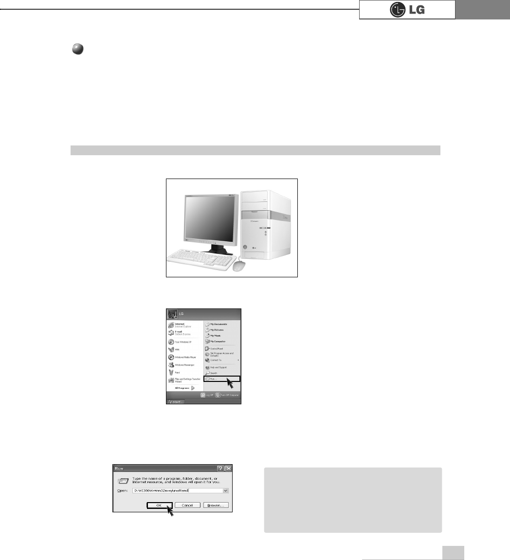
For Windows users
If Windows XP is already installed on the hard disk, you can upgrade existing
Windows XP without formatting the hard disk
In the case that Windows XP is already running on the hard disk, upgrade
Windows XP as follows.
ⓟ
Click the [Start] and [Run] button.
ⓠ
Insert the Restore CD, and input D:\i386\winnt32.exe/unattend. Then, click the
[OK] button. (When the CD-ROM drive is D drive.)
ⓞTurn on the system where Windows XP is installed.
Installation of Windows XP Upgrade
ãTo execute "winnt32.exe" without using
"Unattend" option, you must input the
product key attached on the computer.
You also need to have the computer
certified within 30 days after this
Note
5. Reinstallation of Drivers
58 Reinstallation of Drivers
You must install the printer driver after connecting the printer. Windows XP can
automatically detect printer drivers. However, if Windows XP does not detect your
printer driver, install the printer driver as follows.
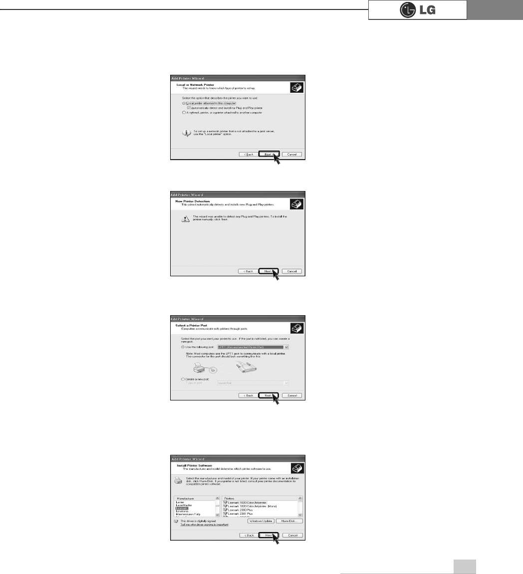
5-1.Reinstalling Printer Driver
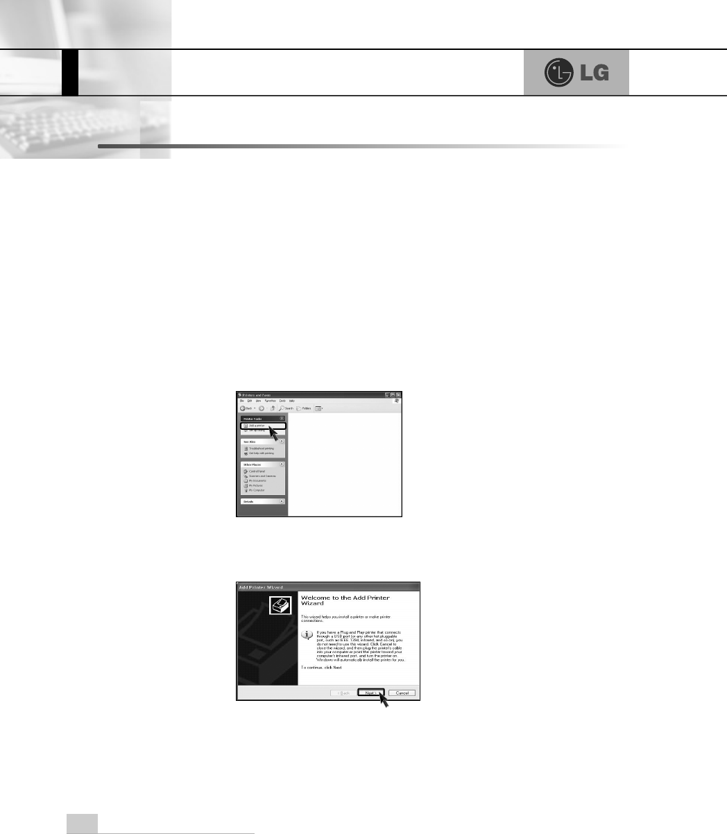
ⓟDouble click the [Printer and Fax] on the Control Panel window.
ⓠWhen the following screen appears, click the [Add Printer] button.
ⓞSelect [Start] è
è[Control Panel] è[Class Desktop].
ⓡWhen the Add Printer Wizard appears, click the [Next] button.
59Reinstallation of Drivers
ⓢWhen the following screen appears, check the connection type of the printer -
local or network. Then, select a printer and click the [Next] button.
ⓣNew Printer Detection screen will appear. Click the [Next] button.
ⓤWhen Set Printer Port screen appears, select LPT1 or LPT2 before clicking the
[Next] button.
ⓥSelect the manufacturer and model of your printer on the Select Printer screen.
If your printer came with an installation disk, click [Have Disk]. If not, just click
the [Next] button.
60 Reinstallation of Drivers
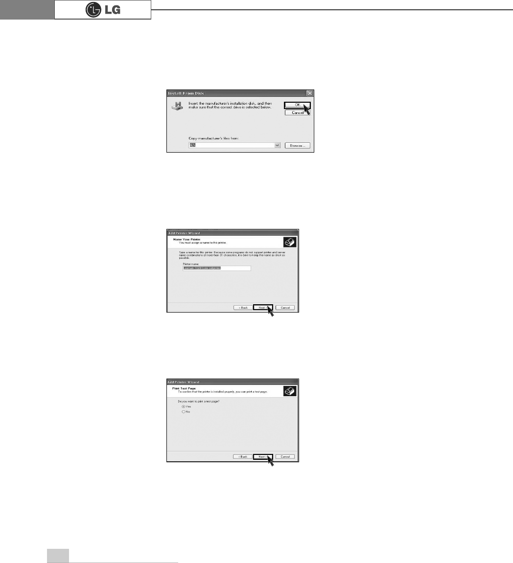
ⓧWhen Print Test Page screen appears, click the [Yes] and [Next].
ⓦInsert the diskette or driver CD in the driver and click the [OK] button.
ⓦName the printer, and click the [Next] button.
When [Have Disk] is selected.
When [Next] is selected
61Reinstallation of Drivers
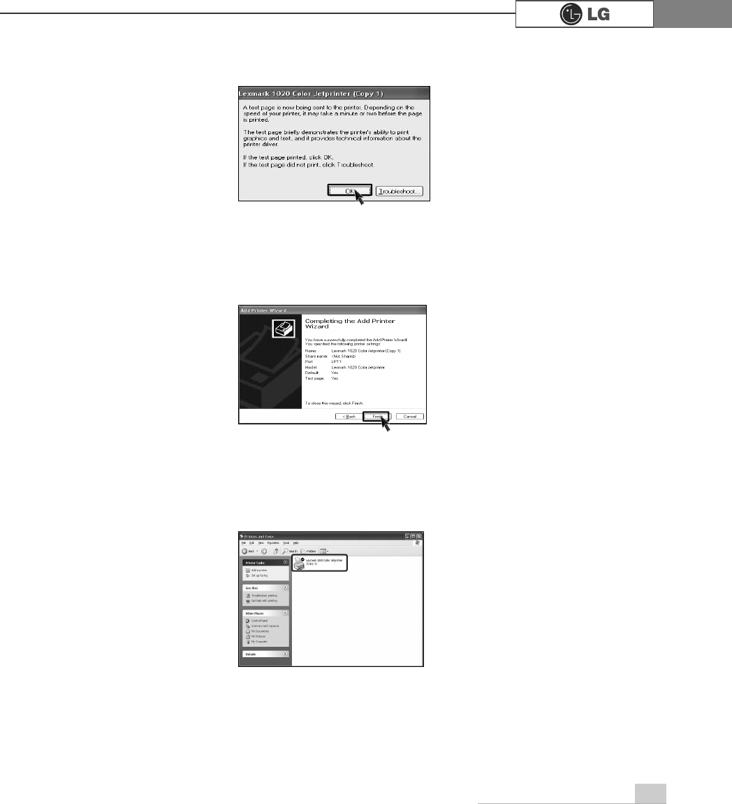
ⓨAfter the test page is properly printed out, click the [OK] button.
ⓩWhen the following screen appears, check the printer and click the [Finish]
button.
⓪Now, the printer has been added. .

62 Reinstallation of Drivers
You must install a sound driver to listen to music files and CDs on the computer. A
sound driver basically comes out with the computer. If it has to be reinstalled,
however, follow the process below.
5-2.Reinstalling Sound Driver
ⓞTurn on the computer and the monitor.
ⓟInsert LG GILJABI CD in the CD-ROM driver. Select the sound driver to install
from the list.
ⓠThe driver installation process will start. Follow instructions on the screen.
63Reinstallation of Drivers
The video driver displays on the monitor data stored on the computer. The video
driver is included in basic specification of the computer. However, in the case that
it is necessary to reinstall the video driver, carry out the following process.
5-3.Reinstalling Video Driver
ⓞTurn on the computer and the monitor.
ⓟInsert LG GILJABI CD in the CD-ROM driver. Select the video driver to install
from the list.
ⓠThe driver installation process will start. Follow instructions on the screen.
ãWhen the computer uses the Intel Onboard Video, some games and programs that does
not support Screen Rotation may not be executed on the screen. When this happens,
disable the Screen Rotation.
Note
System Expansion
66
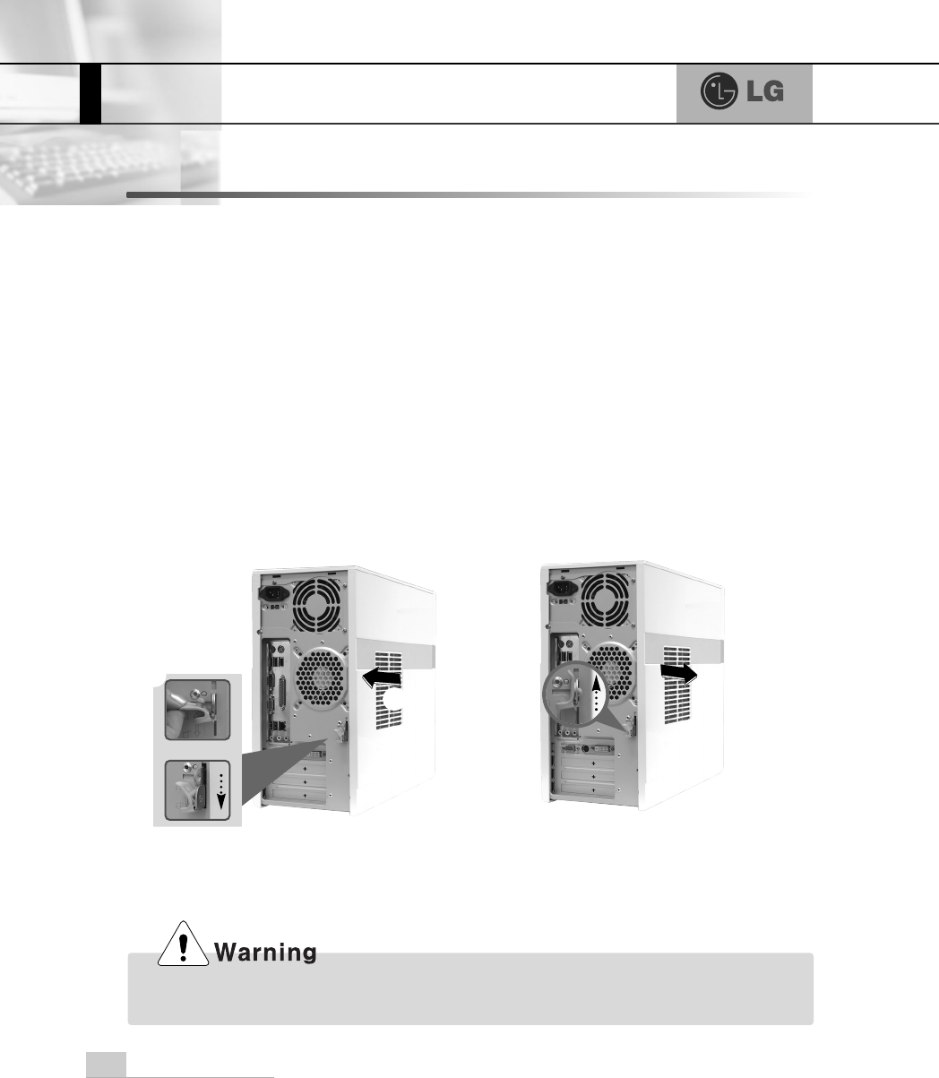
6-1. Opening the computer case
Always consult with your service representatives before opening the computer
case.
Follow the guidelines below when opening the case.
Opening and closing the computer case
ãQuit all running programs.
ãTurn off the computer and monitor, and unplug and remove the power cords.
ãKeep magnetic objects such as screw driver away from the parts inside the com-
puter.
ãOpen the computer case in a safe, clean area.
ãThe static electricity can damage the parts inside the computer. Touch a bare,
unpainted metal part of the computer for 2~3 seconds to remove the static elec-
tricity before opening the computer case.
ãAlways wear gloves to avoid injury when disassembling the computer.
Make sure that there is no metallic object left inside the computer before closing the case.
There is the risk of electric shock or fire.
6. System Expansion
℘
ℙ
⍰
Push the cover in the direction of
arrow as it aligns the groove of com-
puter cover with body shown on the
picture and fasten 3 screws.
Remove 3 screws from the cover and
then push the cover as the direction of
the arrow.
System Expansion 67
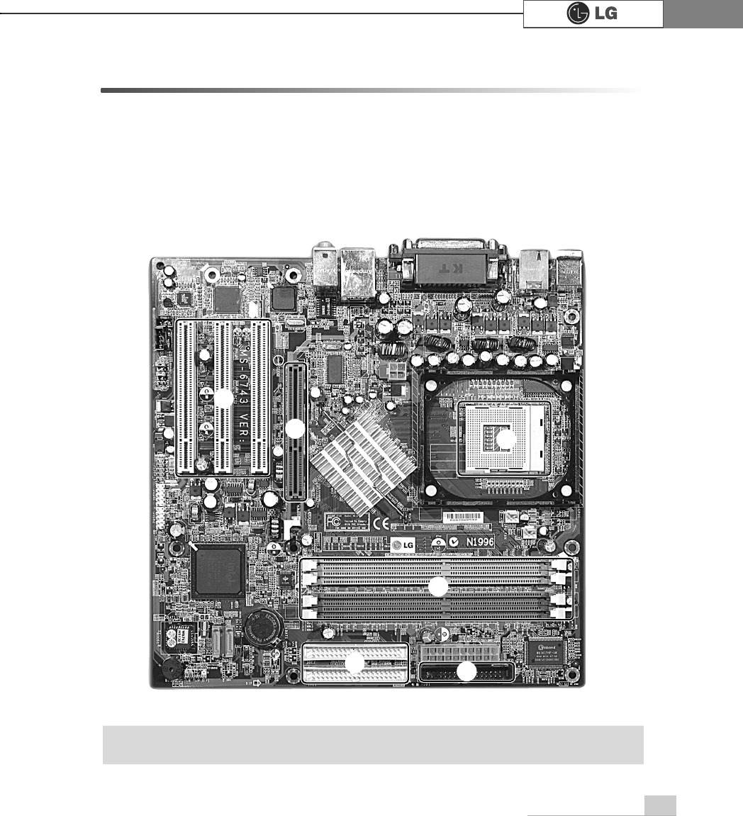
6-2. Main board
The main board determines the model name of your computer. Check the model
name on a label located at the rear of your computer before system expansion.
℘PCI slot
ℙ
ℙAGP slot
ℚCPU socket
ℛ
ℛMemory socket (DIMM)
ℜFloppy disk connector
ℝ
ℝHard disk/CD-ROM connector
℘
ãThe main board in your computer may look different from the picture.
Note
ℙℚ
ℛ
ℜ
ℝ
System Expansion68
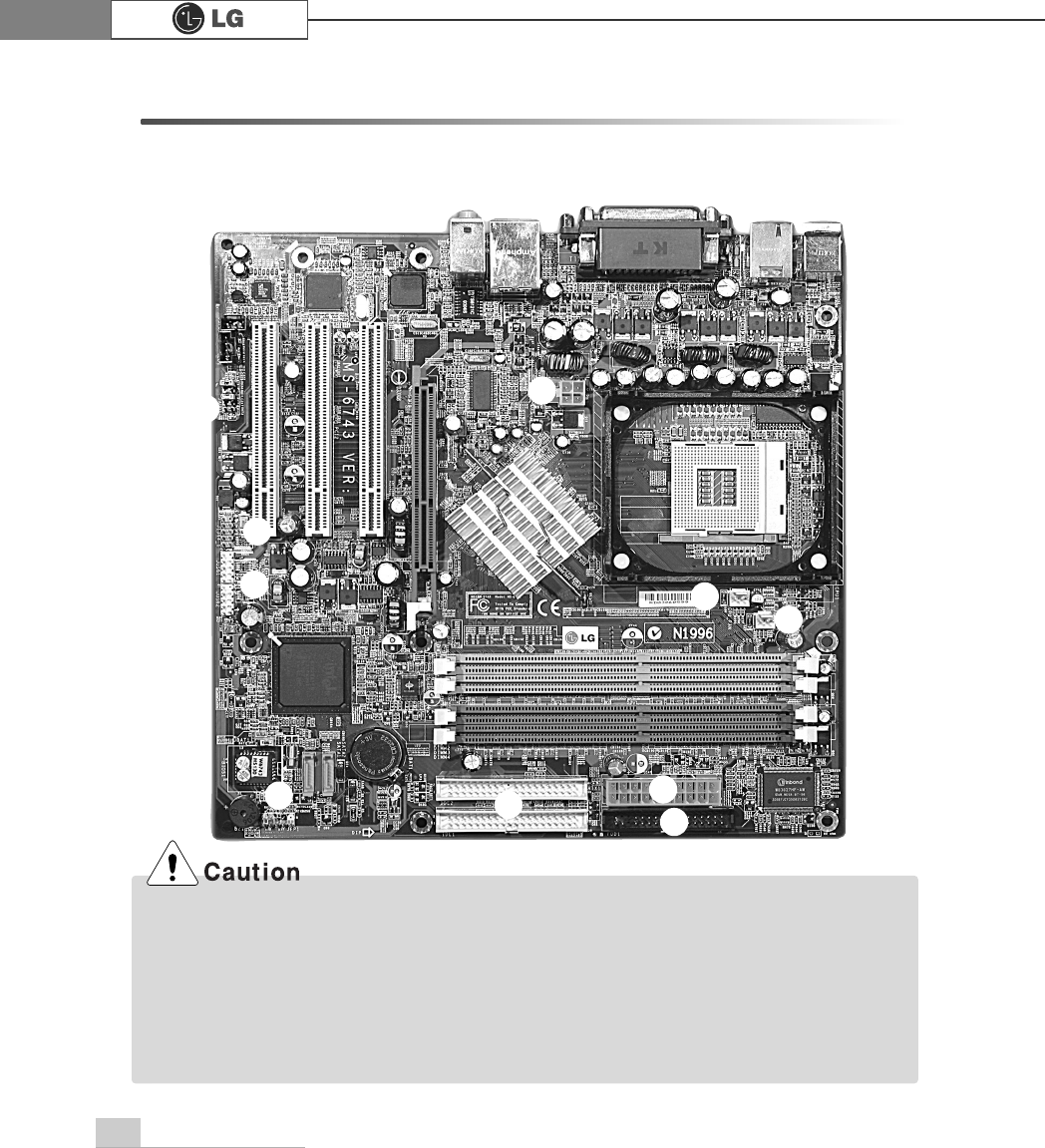
6-3. Connectors
The peripheral devices are connected to the main board through the connectors
shown below. (The main board in your computer may look different from the picture
below)
ãBefore removing the connector, check the status of connection and make a note.
ãAline the groove to the right direction when connecting floppy disk drive connector, hard
disk/CD-ROM connector.
ãMatch the pin number with the color of cable. There is a risk of disfunction to the computer.
ãThere is a risk of explosion if battery is replaced by an incorrect type. Dispose of used batter-
ies according to the instructions.
ãThere is a risk of explosion if the backup(standby) RTC battery is replaced by an incorrect type.
ãDispose of used backup(stadby) RTC battery according to your local ordinances or regulation.
℘ℙ
ℚℛ
℠℡
ℜ
℞
ℝ
℟
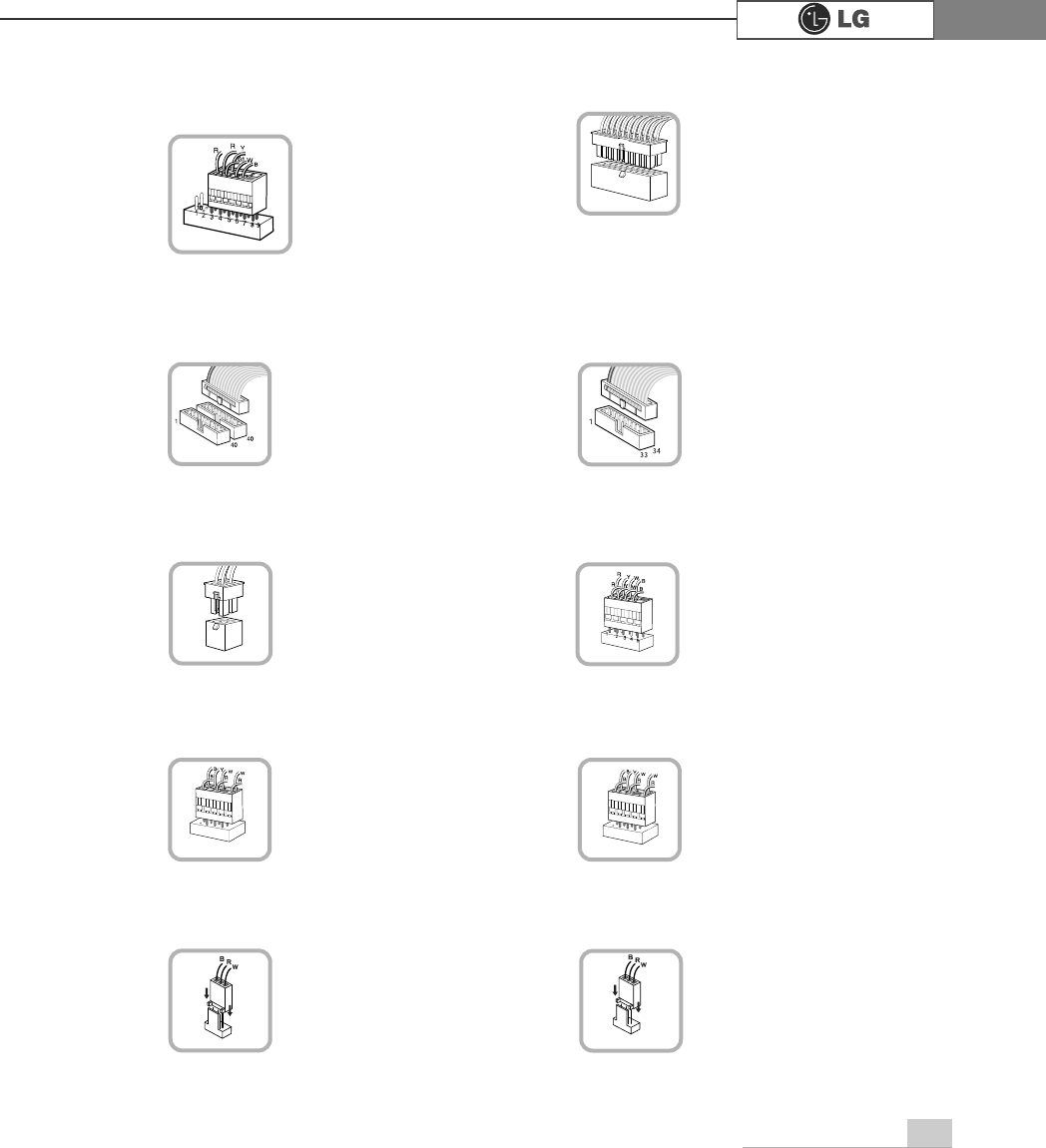
System Expansion 69
℘Power switch, power/ hard disk activity
LED connector (JFP1)
Connects to the power
supply.
ℜPower connector (JPW1: 4 pins)
Connects to the power.
ℙPower connector (CONN1: 20 pins)
Connects to the USB on
the front of the computer.
ℝUSB connector(JUSB1: 10 pins)
Connects power switch
and hard disk activity
LED .
JFP1
ATX1
JPW1 JUSB 1
Connects to the
IEEE 1394 on the front
of the computer.
℞1394 connector (J1394 : 7pins)
J1394
Connects to the head-
phone and microphone
jacks on the front of the
computer.
℟Audio connector(JAUD1: 7 pins)
JAUD1
Connects and supplies
power to the CPU fan.
℠CPU fan (CPU_FAN: 3 pins)
CPU_FAN
IDE connector connects
hard disk and CD-ROM
drive. If only one hard disk
is connected, it should be
connected to IDE1 hard
disk connector.
Connects to the floppy
disk drive.
ℚHard disk/CD-ROM drive connectors
(IDE1, IDE2: 40 pins)
ℛFloppy disk drive connector
(FDD1: 34 pins)
IDE1 IDE2 FDD1
Connects and supplies
power to the system fan
at the bottom of the
computer.
℡System fan (System_FAN)
SYSTEM_FAN