LG Electronics USA DT-KG PERSONAL COMPUTER User Manual
LG Electronics USA PERSONAL COMPUTER Users Manual
Contents
- 1. USERS MANUAL 1
- 2. USERS MANUAL 2
- 3. USERS MANUAL 3
- 4. USERS MANUAL 4
USERS MANUAL 4
System Expansion70
6-4 Replacing the CPU
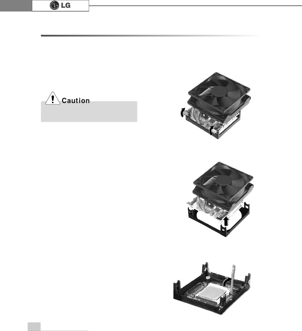
The shape and replacement method of the CPU fan may be different depending on
the model.
ⓠAfter releasing the clamps, lift and remove the CPU.
ⓞ
Remove 4 screws and then disassemble the computer case as the arrow indic
ates.
Align the groove to the right position,
pins can easily be broken.
ⓟClamps on both sides of the CPU fasten the fan tightly to the CPU socket.
raise the handle℘, release the clamps, and then spread them outwardℙ.
System Expansion 71
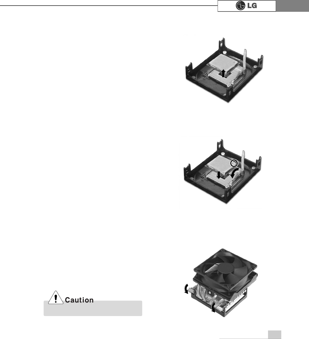
ⓢLift the CPU straight up. Be careful not to damage the pins at the bottom of the CPU.
ⓡRaise the handle on the CPU socket to unlock the CPU.
Always wear gloves to avoid injuries.
ⓣAlign the identifying marks at the corners of the new CPU and socket, and care-
fully install the CPU in the socket. Lower the handle to lock the CPU in place.
72 System Expansion
ⓞ
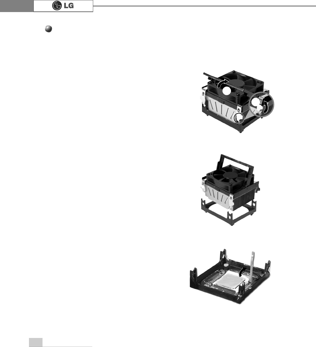
Clamps on both sides of the CPU fasten the fan tightly to the CPU socket.
raise the handle℘, release the clamps, and then spread them outwardℙ.
ⓟ
After releasing the clamps, lift and remove the CPU fan from the socket.
ⓠ
Raise the handle on the CPU socket to unlock the CPU.
ℙ
℘
Replacing CPU
73System Expansion
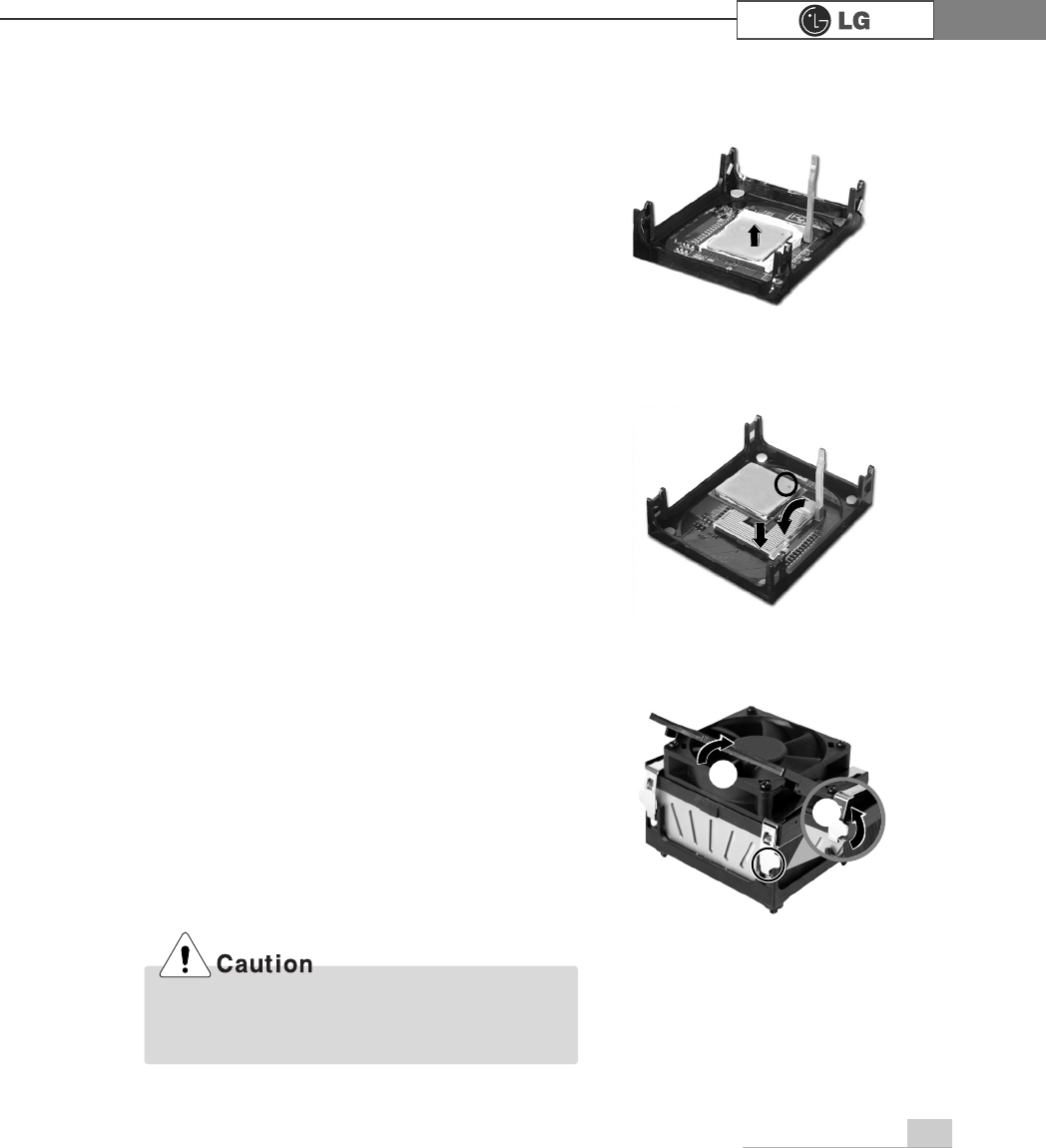
ⓢAlign the identifying marks at the corners of the new CPU and socket, and careful-
ly install the CPU in the socket. Lower the handle to lock the CPU in place.
ⓣLower the handle as shown picture℘and lock the clamps as shown picture ℙ.
ⓡLift the CPU straight up. Be careful not to damage the pins at the bottom of the
CPU.
In a specific system, clamps are not fully open.
Raise the CPU fan from the fully opened space.
To assemble it, install from the opposite side.
ℙ
℘
74 System Expansion
6-5. Increasing the memory
If you run out of memory while using the computer, you may want to increase the
amount of memory in your computer.
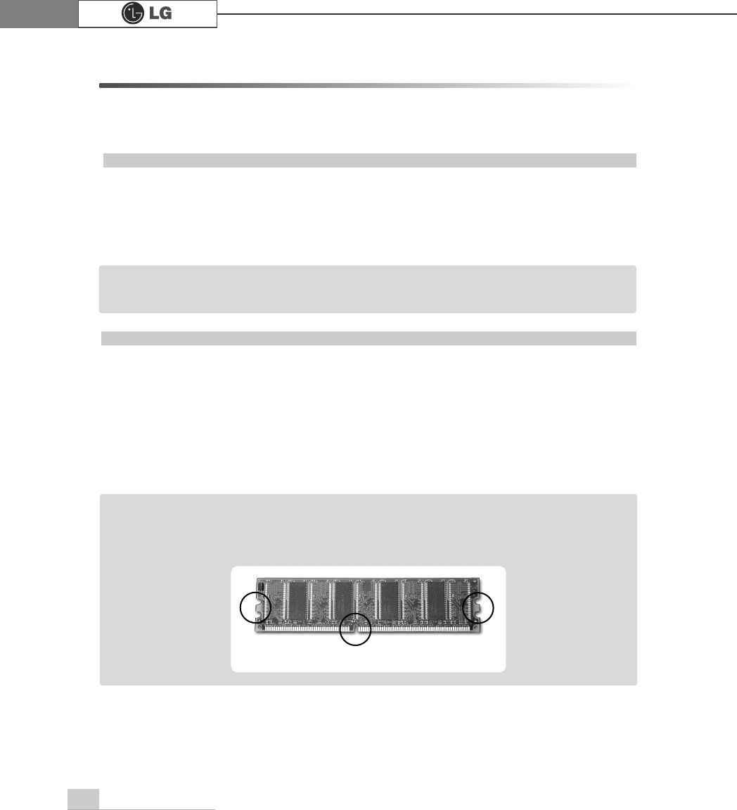
About memory
Your computer uses DDR(Double Data Rate) SDRAM DIMM(Dual In-Line Memory
Module) with 184 pins. Your computer supports Unbuffered DDR SDRAM DIMM of
128MB up to 1024MB in size in each socket, and 2048MB total.
Before increasing the memory
ãAlways wear gloves to avoid injury when disassembling the computer
ãStatic electricity can damage memory modules be sure to minimize the static
electricity when replacing memory.
ãMake sure to replace the memory of the same type as the installed memory.
ãDIMM is different from SIMM in that it is configured for 64 bit operation; therefore,
your computer can operate with only one DIMM installed.
ãWindows 95, 98SE, ME supports memory up to 512MB total. Increasing the memory
beyond 512MB in these systems may cause errors while using the computer.
Note
ãUse a 2.5V DDR SDRAM DIMM.(The shape of the memory may be different depending
on the model) DDR SDRAM enhances the rate of data transmission of the SDRAM and
looks different from SDRAM.
Note
DDR
75System Expansion
Purchasing a memory
Check the type of memory installed in your computer and refer to the memory configura-
tion chart before purchasing a memory.
Specification: PC2700/3200(184 pin DDR SDRAM DIMM)
Speed: 333MHz(166MHz X 2), 400MHz(200MHz X 2)
Size: 256MB, 512MB
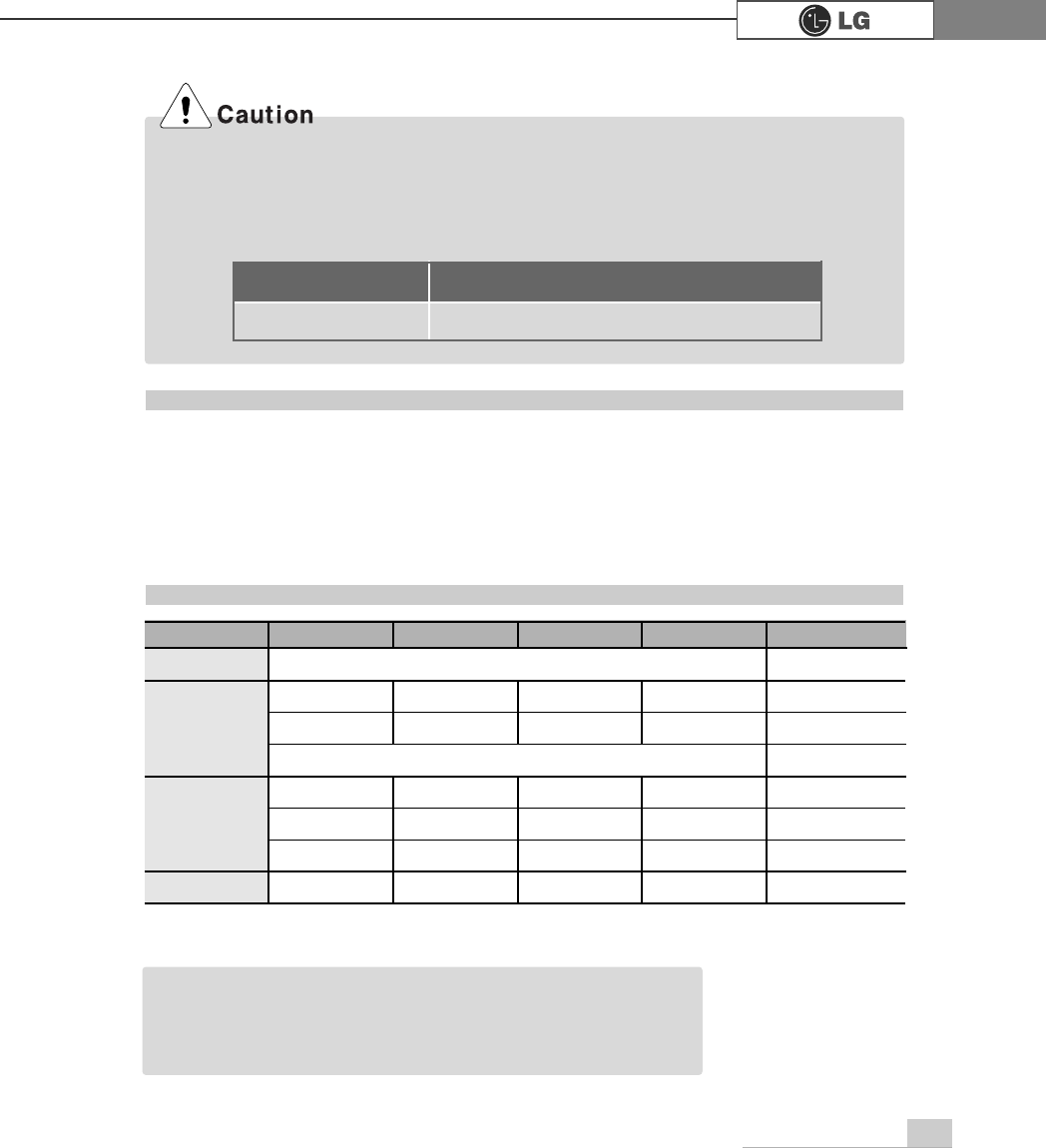
Memory configuration chart
Total memory DIMM 1 DIMM 2 DIMM 3 DIMM 4
DUAL/SINGLE
SINGLE
DUAL
DUAL
SINGLE
DUAL
DUAL
DUAL
DUAL
512MB
256MB 256MB
256MB 256MB
256MB
1024MB
256MB 256MB 256MB 256MB
512MB 512MB
512MB 512MB
2048MB 512MB 512MB 512MB 512MB
512 (1/4)
256
ãYour computer supports PC2700/3200 DDR memory.
ãUse Unbuffered DDR SDRAM DIMM only to increase the memory.
ãDual channel mode operates when each identical memory is installed in the same color
of DIMM slot.
FSB Frequency
533/800MHz
Supported memory type
PC2700/3200-DDR SDRAM 333/400MHz
ãDual channel improves the efficiency of the system.
ãEach identical memory should be used for dual channel setting.
ãDual channel setting is recommended.
Note
76 System Expansion
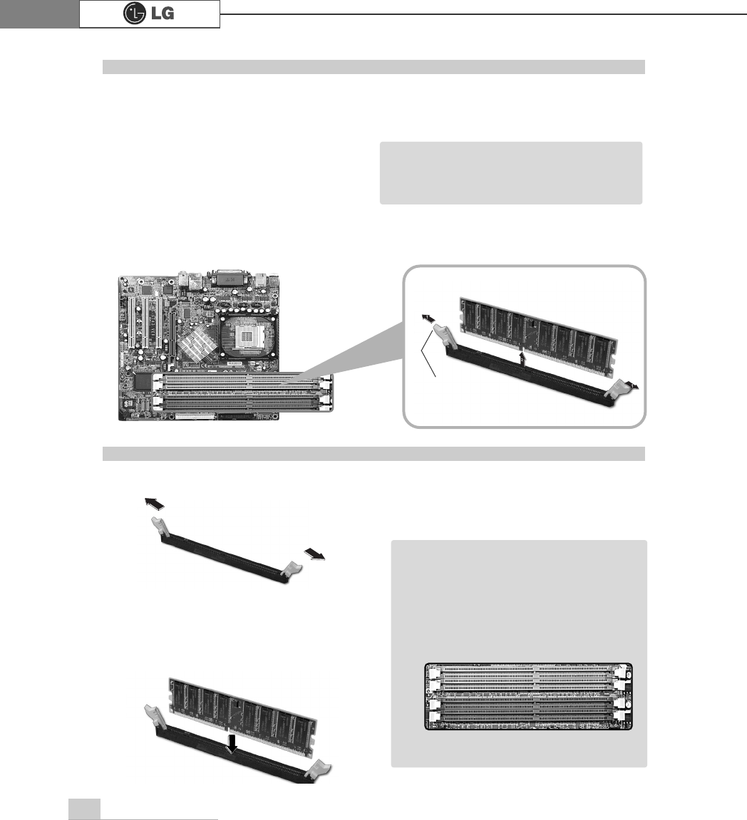
The main board configuration, memory socket, and the shape of memory may be
different depending on the model.
ⓞRemove the screws on the rear of
the computer, and open the com
puter case.
ⓞ
Pull the latch on each side of a memory socket.
ⓟPull the latch on each side of a memory socket to release the memory.
Replacing the memory
ⓟ
Align the notch at the bottom of the
memory with a protrusion in the middle
of the socket, and then insert the
memory straight down.
Installing a memory
Latch
ãBefore opening the case, turn off the
computer and peripheral devices, and
remove the power cords.
Note
ãFor dual channel system, each mem
ory should be installed in independent
slot(1&3 slot or 2&4 slot) when using
DDR Memory
It is recognized as a single channel if
there is a difference between dual
channel 1 and 3, 2 and 4.
Note
℘
ℙ
ℚ
ℛ
Firmly push the latch to lock the memory.
77System Expansion
Checking the size of the installed memory
The computer automatically recognizes the newly installed memory; therefore,
you do not need to change the system setup. Follow the instruction below to
check the size of the installed memory.
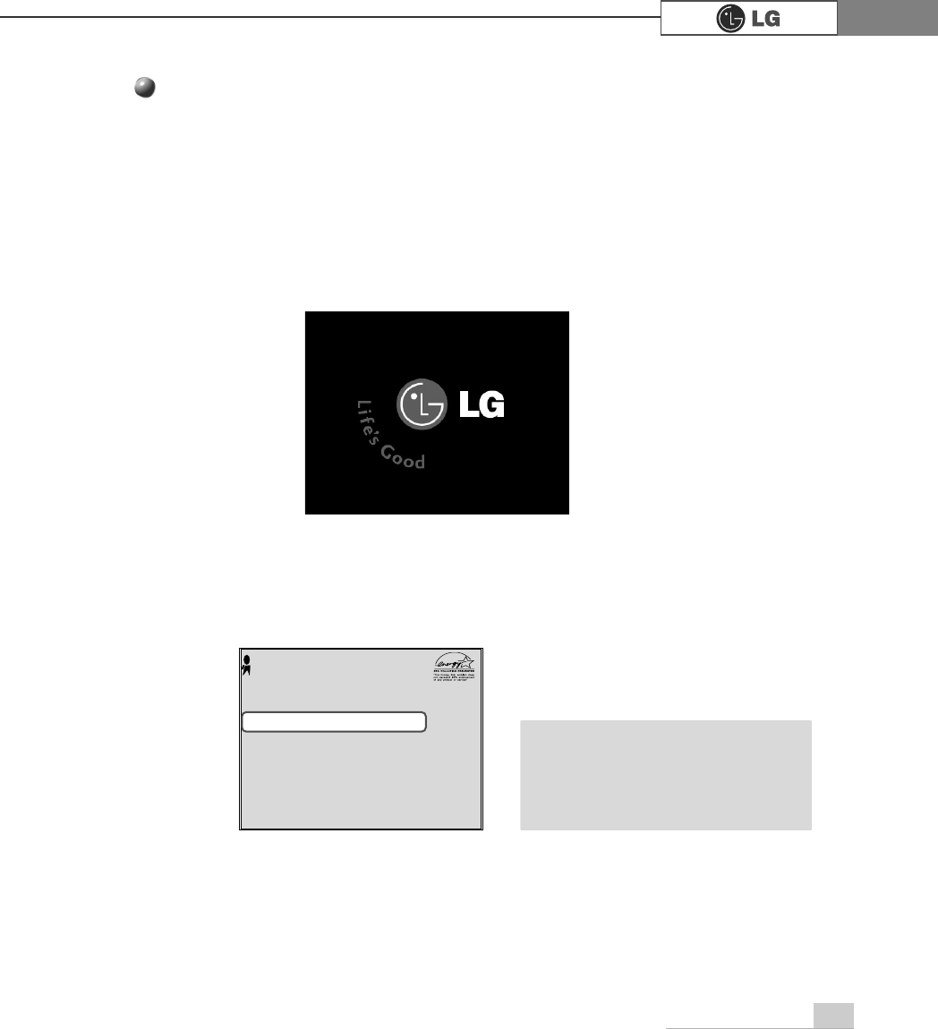
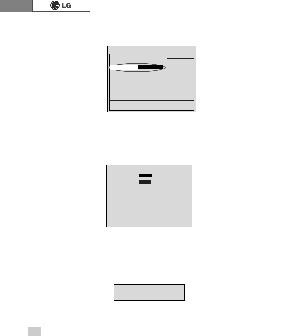
ⓞConnect the power cord and other devices, and turn on the computer and monitor.
The following screen appears to inspect the status of the computer.
ⓟIf the following screen appears, press [Esc]. POST screen appears.
ⓡAfter check the memory, press [Esc]. Windows screen appears.
ⓠIf the following screen appears, press [Pause] key to pause the screen. Make
sure [Memory Testing : XXXXXX OK] appears.
Award Modular BIOS vX.XXXX, An Energy Star Ally
Copyright(C) 1984-2004, Award Software, Inc.
Build ID : LG XXXX XX.XX XX:XX:XX
Main Processor : Intel(R) Pentium(R) X Processor XXXMHz
Memory Test : XXXXXX OK
Press DEL to enter SETUP
XX/XX/XX-XXXX-XXXX-XXXXXXXXX-XX
0HPRU\7HVWLQJ;;;;;;2.
ã
To stop the logo screen for a moment,
press [Delete] key ⎀Advanced BIOS
Features ⎀Full Screen Logo Show
Selectable, and then select Disable.
Note
78 System Expansion
6-6. Adding a hard disk drive
Your computer supports up to 4 E-IDE controllers and 2 hard disk drives.
The following instruction describes the most typical configuration where your comput-
er already has a master hard disk drive and you are adding a slave hard disk drive.
ãAlways wear gloves to avoid injury when disassembling the computer.
ãIf the master hard drive is set to CS(Cable Select), the slave drive must also be set to
CS(Cable Select).
ãUsing screws other than the ones provided with the hard disk drive can damage the drive.
Using longer or thicker screws can be fatal to the disk drive. A hard disk drive must be
mounted securely in order to provide reliable performance.
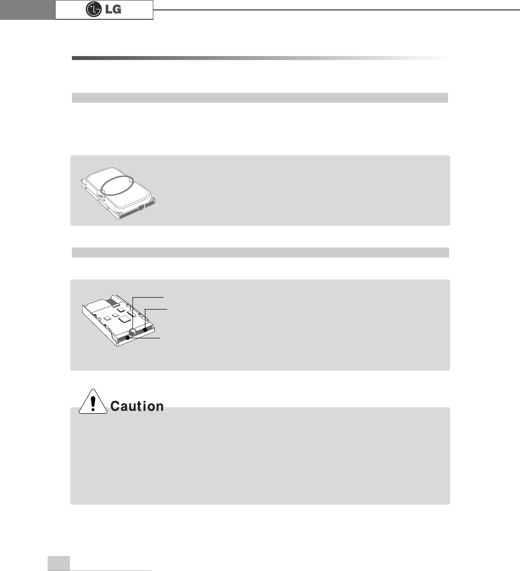
Before adding a hard disk drive
Adding a hard disk drive
ãCheck and write down the jumper settings, size, and number of
cylinders, heads, and sectors of the hard disk drive where you
can refer to when you use the system setup.
(Some hard disk drives do not have the information written on the drive)
Note
Note
Power connector
Signal cable
connector
Jumper ãPrepare the hard disk you want to add.
ãPurchase an E-IDE hard disk drive.
ãSet the jumper setting in the slave hard to SL: Slave.
ãThe jumper settings differ from one hard disk
drive to another, so make sure you follow the
jumper setting information on top of the drive.
79System Expansion
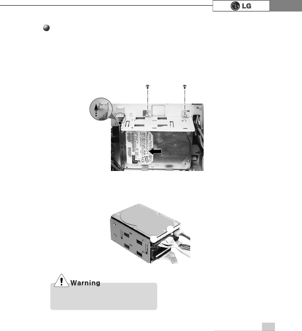
Adding a hard disk drive
ⓟRemove 4 screws on the hard drive case and open the hard drive case as the
direction of the arrow.
ⓞRefer to Opening the computer case (page 66) to remove the computer case
cover.
ⓠConnect the power cable connector as shown No1 and the signal cable connec-
tor as shown No 2 to the new hard disk you want to replace in the hard disk
case.
Incorrect connection of the signal and
power cord may cause disfunction to the
computer or electrical shock.
℘
ℙ
80 System Expansion
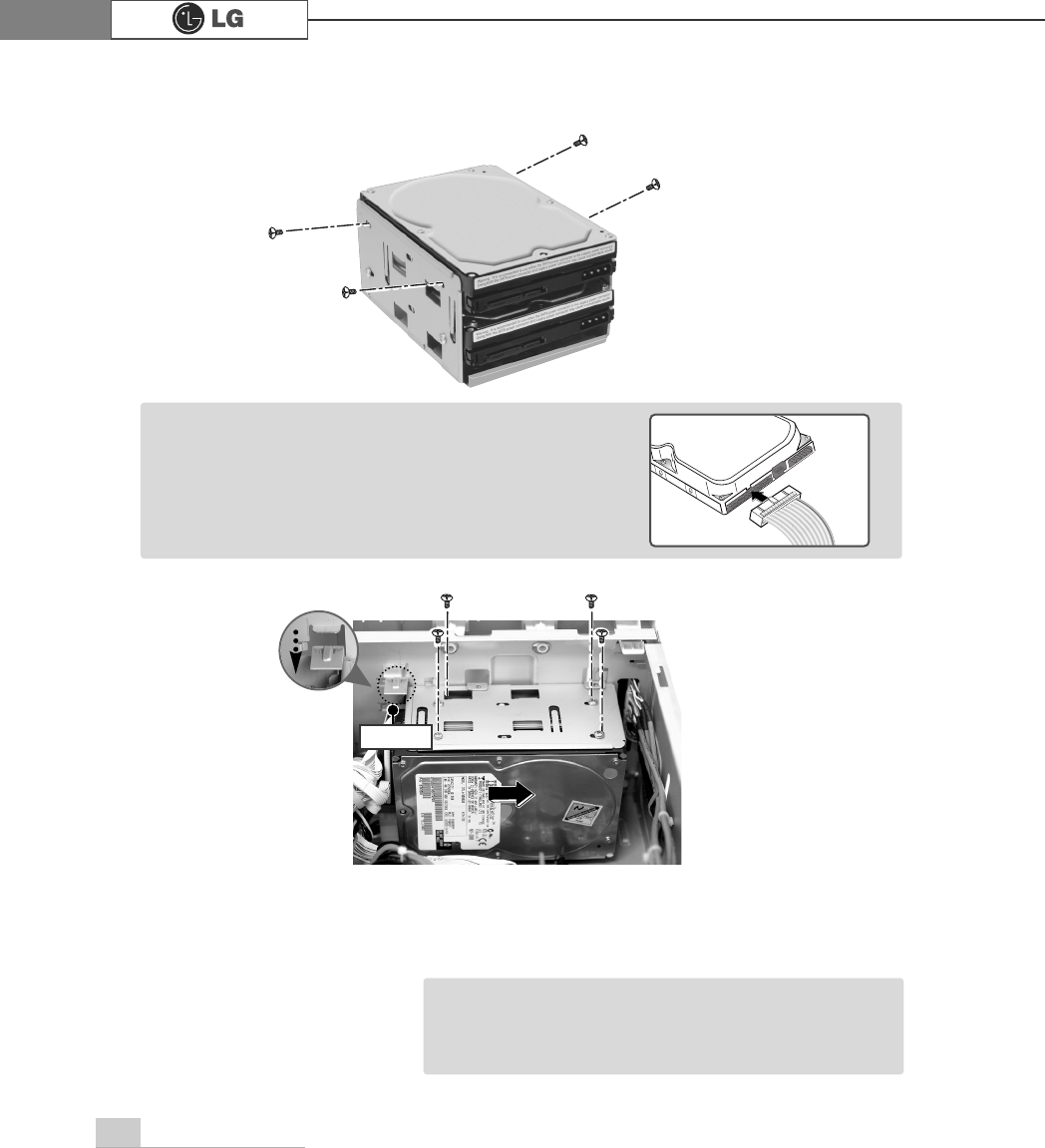
ⓣRefer to Closing the computer case (page 66) to close the computer case cover.
ⓢFasten 4 screws after installing the hard disk drive as shown on the picture.
ãYou should setup and format your computer after
installing the hard disk. Refer to the Hard disk setup
(page82).
Note
Ӌીણௗ
ⓡInstall the hard disk drive case to the computer and fasten the 4 screws.
ãIncorrect connection of the power and signal cables to
a hard disk drive may damage the drive.
Note
81System Expansion
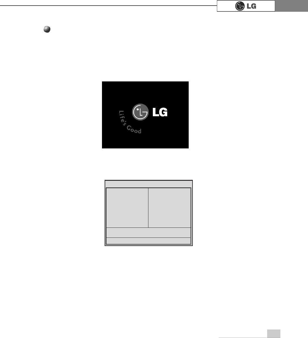
ⓞTurn on the computer and monitor.
ⓟ
Press [Delete]key when the logo screen appears.
ⓠThe CMOS Setup Utility opens.
ⓡ
Use arrow
>Ⓑ@>Ⓒ@>⒵@
, and
>Ⓐ@
keys to select Standard CMOS Features, and
press Enter.
Hard disk drive setup
3KRHQL[$ZDUG%,26&0266HWXS8WLOLW\
Ě 6WDQGDUG&026)HDWXUHV Ě
3&+HDOWK6WDWXV
Ě $GYDQFHG%,26)HDWXUHV Ě )UHTXHQF\9ROWDJH&RQWURO
Ě $GYDQFHG&KLSVHW)HDWXUHV /RDG2SWLPL]HG'HIDXOWV
Ě ,QWHJUDWHG3HULSKHUDOV 6HW3DVVZRUG
Ě 3RZHU0DQDJHPHQW6HWXS 6DYH([LW6HWXS
Ě 3Q33&,&RQILJXUDWLRQV ([LW:LWKRXW6DYLQJ
(VF4XLW êëè é 6HOHFWOWHP
)6DYH([LW6HWXS
9LUXV3URWHFWLRQ%RRW6HTXHQFH
82 System Expansion
ⓢ
Use arrow
>Ⓑ@>Ⓒ@>⒵@
, and
>Ⓐ@
keys to select IDE Channel 0 Slave, and press
[Enter].
ⓣ
After setting IDE Channel 0 Slave to Auto by pressing [Enter], press [Enter] in
IDE HDD Auto-Detection so the system automatically recognizes the newly
installed slave hard disk drive.
ⓤPress [F10] to save the new setting.
ⓥIf the following message appears, press [Enter]. The computer restarts.
Data (mm:dd:yy) XXX, XXX, XXXX
Time (hh:mm:ss) XX, XX, XX
ĚIDE Channel 0 Master Press EnterXXXXXMB
ĚIDE Channel 0 Slave Press Enter None
ĚIDE Channel 1 Master Press Enter None
ĚIDE Channel 1 Slave Press Enter None
Drive A X.XXM, X.Xin
Drive B None
Video EGA/VGA
Halt On All, But Keyboard.
CPU Type X.XXX.XXX.XX
BIOS Version Build ID :LG
Video Memory X.XX K
System Memory X.XX K
Total Memory X.XX K
Item Help
Menu Level Ě
Press [Entre] to enter
next page for detail
this drive settings
êëèé:Move Enter:Select +/-/PU/PD:Value F10:Save ESC:Exit F1:General Help
F5:Previous Values F7:Optimized Defaults
Press Enter None
Ě
IIDE Channel 0 Slave
IDE HDD Auto-Detection
Press Enter
IDE Channel 0 Slave Auto
Access Mode Auto
Capacity 0 MB
Cylinder 0
Head 0
Precomp 0
Lauding Zome 0
Sector 0
Item Help
Menu Level Ě
To auto-detect the
HDD±s size, head...on
this channel
êëèé:Move Enter:Select +/-/PU/PD:Value F10:Save ESC:Exit F1:General Help
F5:Previous Values F7:Optimized Defaults
$XWR
3UHVV(QWHU
SAVE to CMOS and EXIT(Y/N)? Y
Phoenix-Award BIOS CMOS Set up Utility
IDE Channel 0 Slave
Phoenix-Award BIOS CMOS Set up Utility
Standard CMOS Features
83System Expansion
Hard disk setup (Hard disk with factory default setting)
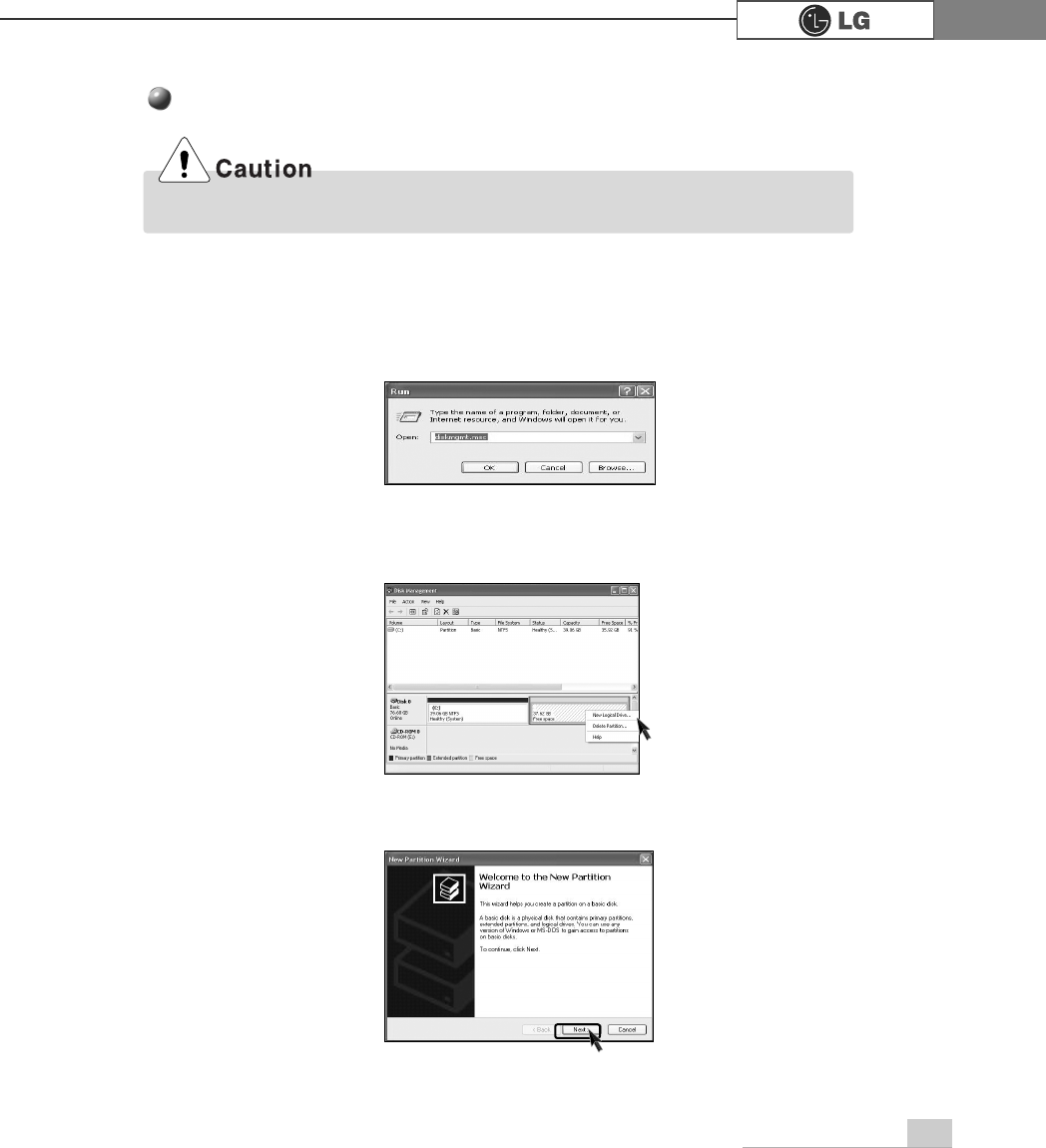
ⓞClick [Start] and [Run].
ⓟType 'diskmgmt.msc' and press [OK].
ⓠIf the following window appears, select disk1. Click right button on the mouse to
select New partition.
ⓡClick [Next] if the following message appears.
Be careful, Using <diskmgmt.msc> to divide partition delete data in a selected driver.
84 System Expansion
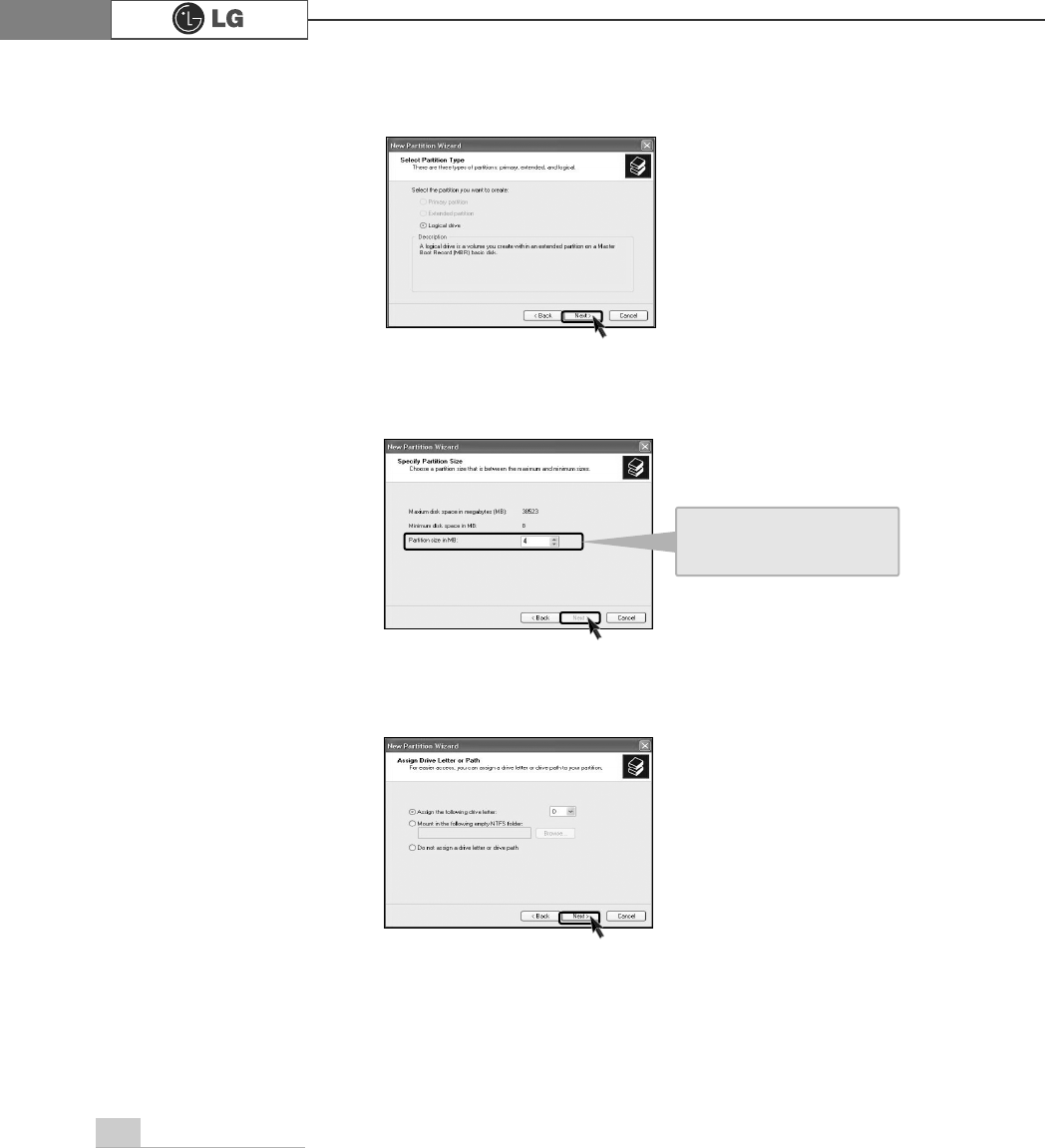
ⓢSelect a partition and click [Next].
ⓣSelect the maximum size and click [Next].
ⓤClick [Next] after selecting a drive value.
A selected space of the
disk will be available to
use.
85System Expansion
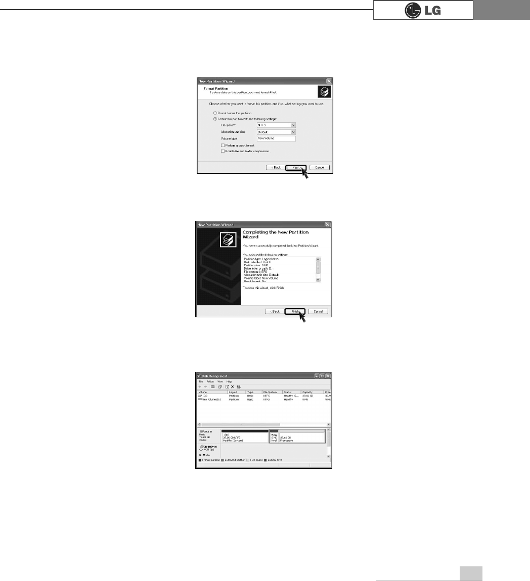
ⓥIf the following window appears, select File system, Allocation unit size and
Volume label ,and click [Next].
ⓦNew Partition Wizard is complete, click [Finish].
ⓧAfter the format is complete, the hard disk operates normally.
86 System Expansion
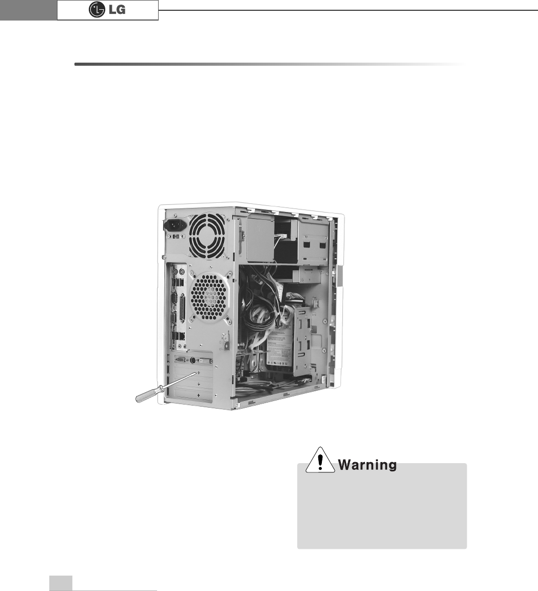
6-7.Installing expansion cards
When you are using the computer, you may need to install expansion cards to
improve funtionality. The following instruction describes how to install expansion
cards.
ⓞRefer to Opening the computer case to open the computer case cover.
ⓟUse the driver and remove the metal slot cover.
(Remove it, only when installing an additional extension card.)
ãAlways use a screwdriver to open
the case cover. There is the risk of
injury.
ãIn order not to be injured when dis-
assembling the computer, wear the
gloves.
87System Expansion
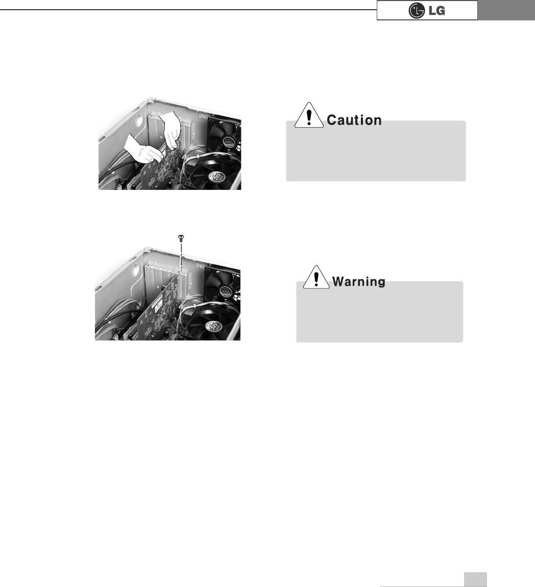
ⓢInstall the driver program for the new expansion card.
ⓡFasten 2 screws after installing the extension slot.
ⓠHold the expansion card with both hands and align the expansion card and slot.
Push down evenly to insert the card into the slot.
ãIncorrect installation of an expansion
card may damage the main board
and result in a computer malfunction.
ã
Using the computer without closing
the case may result in fire, electric
shock, injury, and/or damage to the
computer.

88 Specifications
Specifications *
.*PRGHO
Floppy disk drive One 3.5inch 1.44MB drive
Keyboard PS/2 keyboard (104keys)
Mouse PS/2 mouse or USB (ball / wheel)
Video Integrated or external AGP graphic
Sound Built-in AC'97 audio. Support MIC-IN, SPEAKER-OUT and
LINE-IN.(Support virtual 5.1 channel output)
System memory
Cache memory
L1: 8KB/16KB or above, L2: 128KB/256KB/512KB/1024KB or above.
Hard disk drive 40GB or above (E-IDE type)
LAN Integrated 10/100Base-T Ethernet
USB 6ports (support USB 2.0)
Serial I/O One RS-232C (9pins)
Parallel I/O One printer port (25pins)
IEEE1394 One 1394(Front), One 1394(Rear)
Front I/O
One 1394 port, Two USB ports and audio ports (SPEAKER-OUT and MIC-IN)
Extension slot One AGP
Product size Width 170 x Height 357 x Depth 406(mm)
Cable Power cable length 1.8m
Power spec 100~127 / 200~240VAC, 6.3/4A, 50/60Hz or
200~240VAC. 4A, 50/60Hz
CPU Intel Pentium 4 / Celeron mPGA478 type (2.4GHz or above)
ÚÚSpecifications below differ depending on the models.
256MB (up to 2.0 GB) - If built-in VGA is used, maximum 16MB
and minimum 1MB is applied for Video Frame buffer in DOS
Mode, but Windows Mode automatically manages the video
memory (up to 96MB depending on System Memory size).
Temperature:Average temperature:77ĕ(25Ë
Operating temperature:41ĕ~95ĕ(5~35Ë
Storage temperature:-4ĕ~131ĕ
-25~55Ë
Humidity:Average humidity:60%(RH)
Operating humidity:30%~80%(RH)/Storage humidity:30%~80%(RH)
Environmental
requirement
Option mark
1394 port(Front/Rear)
This equipment has been tested and found to comply with the limits for a Class B
digital device, pursuant to part 15 of the FCC Rules. These limits are designed to
pro-vide reasonable protection against harmful interference in a residential installa-
tion. This equipment generates, uses and can radi-ate radio frequency energy and,
if not in-stalled and used in accordance with the in-structions, may cause harmful
interference to radio communications. However, there is no guarantee that interfer-
ence will not occur in a particular installation. If this equip-ment does cause harmful
interference to radio or television reception, which can be determined by turning the
equipment off and on, the user is encouraged to try to correct the interference by
one or more of the fol-lowing measures:
-. Reorient or relocate the receiving antenna.
-. Increase the separation between the equip-ment and receiver.
-. Connect the equipment into an outlet on a circuit different from that to which the
re-ceiver is connected.
-. Consult the dealer or an experienced radio/TV technician for help.
NOTE
Changes or modifications not expressly approved by the party responsible for
compliance could void the user's authority to operate the equipment.

90 memo
PHPR

91memo
PHPR