LG Electronics USA DT-KG PERSONAL COMPUTER User Manual
LG Electronics USA PERSONAL COMPUTER Users Manual
UserManual.wiki
>
LG Electronics USA
>
DT-KG User Manual
>
USERS MANUAL 4
Contents
1.
USERS MANUAL 1
2.
USERS MANUAL 2
3.
USERS MANUAL 3
4.
USERS MANUAL 4
USERS MANUAL 4
Navigation menu
Upload a User Manual
Namespaces
Wiki Guide
HTML
PDF
Info
Views
User Manual
Discussion / Help
Navigation
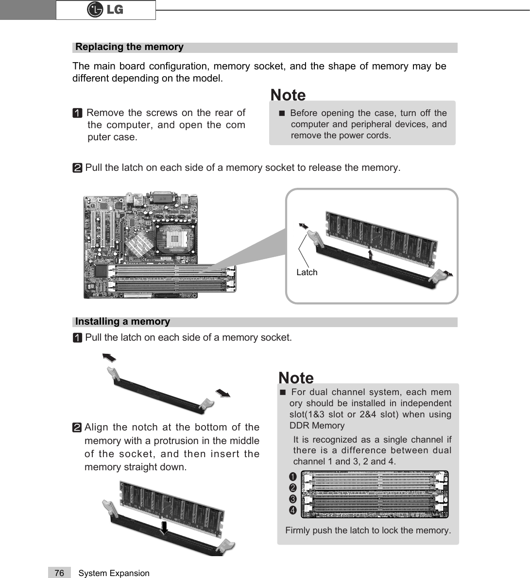
![77System ExpansionChecking the size of the installed memoryThe computer automatically recognizes the newly installed memory; therefore,you do not need to change the system setup. Follow the instruction below tocheck the size of the installed memory.ⓞConnect the power cord and other devices, and turn on the computer and monitor.The following screen appears to inspect the status of the computer.ⓟIf the following screen appears, press [Esc]. POST screen appears.ⓡAfter check the memory, press [Esc]. Windows screen appears.ⓠIf the following screen appears, press [Pause] key to pause the screen. Makesure [Memory Testing : XXXXXX OK] appears.Award Modular BIOS vX.XXXX, An Energy Star AllyCopyright(C) 1984-2004, Award Software, Inc.Build ID : LG XXXX XX.XX XX:XX:XX Main Processor : Intel(R) Pentium(R) X Processor XXXMHzMemory Test : XXXXXX OKPress DEL to enter SETUP XX/XX/XX-XXXX-XXXX-XXXXXXXXX-XX0HPRU\7HVWLQJ;;;;;;2.ãTo stop the logo screen for a moment,press [Delete] key ⎀Advanced BIOSFeatures ⎀Full Screen Logo ShowSelectable, and then select Disable.Note](https://usermanual.wiki/LG-Electronics-USA/DT-KG.USERS-MANUAL-4/User-Guide-519355-Page-8.png)
![81System ExpansionⓞTurn on the computer and monitor.ⓟPress [Delete]key when the logo screen appears.ⓠThe CMOS Setup Utility opens.ⓡUse arrow >Ⓑ@>Ⓒ@>⒵@, and >Ⓐ@keys to select Standard CMOS Features, and press Enter.Hard disk drive setup3KRHQL[$ZDUG%,26&0266HWXS8WLOLW\Ě 6WDQGDUG&026)HDWXUHV Ě3&+HDOWK6WDWXVĚ $GYDQFHG%,26)HDWXUHV Ě )UHTXHQF\9ROWDJH&RQWUROĚ $GYDQFHG&KLSVHW)HDWXUHV /RDG2SWLPL]HG'HIDXOWVĚ ,QWHJUDWHG3HULSKHUDOV 6HW3DVVZRUGĚ 3RZHU0DQDJHPHQW6HWXS 6DYH([LW6HWXSĚ 3Q33&,&RQILJXUDWLRQV ([LW:LWKRXW6DYLQJ(VF4XLW êëè é 6HOHFWOWHP)6DYH([LW6HWXS9LUXV3URWHFWLRQ%RRW6HTXHQFH](https://usermanual.wiki/LG-Electronics-USA/DT-KG.USERS-MANUAL-4/User-Guide-519355-Page-12.png)
![82 System ExpansionⓢUse arrow >Ⓑ@>Ⓒ@>⒵@, and >Ⓐ@keys to select IDE Channel 0 Slave, and press[Enter].ⓣAfter setting IDE Channel 0 Slave to Auto by pressing [Enter], press [Enter] inIDE HDD Auto-Detection so the system automatically recognizes the newlyinstalled slave hard disk drive.ⓤPress [F10] to save the new setting.ⓥIf the following message appears, press [Enter]. The computer restarts.Data (mm:dd:yy) XXX, XXX, XXXXTime (hh:mm:ss) XX, XX, XXĚIDE Channel 0 Master Press EnterXXXXXMBĚIDE Channel 0 Slave Press Enter None ĚIDE Channel 1 Master Press Enter None ĚIDE Channel 1 Slave Press Enter None Drive A X.XXM, X.XinDrive B NoneVideo EGA/VGAHalt On All, But Keyboard.CPU Type X.XXX.XXX.XXBIOS Version Build ID :LG Video Memory X.XX KSystem Memory X.XX KTotal Memory X.XX KItem HelpMenu Level ĚPress [Entre] to enternext page for detailthis drive settingsêëèé:Move Enter:Select +/-/PU/PD:Value F10:Save ESC:Exit F1:General HelpF5:Previous Values F7:Optimized DefaultsPress Enter NoneĚIIDE Channel 0 Slave IDE HDD Auto-DetectionPress EnterIDE Channel 0 Slave AutoAccess Mode AutoCapacity 0 MB Cylinder 0Head 0Precomp 0Lauding Zome 0Sector 0 Item HelpMenu Level ĚTo auto-detect theHDD±s size, head...onthis channelêëèé:Move Enter:Select +/-/PU/PD:Value F10:Save ESC:Exit F1:General HelpF5:Previous Values F7:Optimized Defaults$XWR3UHVV(QWHUSAVE to CMOS and EXIT(Y/N)? Y Phoenix-Award BIOS CMOS Set up UtilityIDE Channel 0 Slave Phoenix-Award BIOS CMOS Set up UtilityStandard CMOS Features](https://usermanual.wiki/LG-Electronics-USA/DT-KG.USERS-MANUAL-4/User-Guide-519355-Page-13.png)
![83System ExpansionHard disk setup (Hard disk with factory default setting)ⓞClick [Start] and [Run].ⓟType 'diskmgmt.msc' and press [OK].ⓠIf the following window appears, select disk1. Click right button on the mouse toselect New partition.ⓡClick [Next] if the following message appears.Be careful, Using <diskmgmt.msc> to divide partition delete data in a selected driver.](https://usermanual.wiki/LG-Electronics-USA/DT-KG.USERS-MANUAL-4/User-Guide-519355-Page-14.png)
![84 System ExpansionⓢSelect a partition and click [Next].ⓣSelect the maximum size and click [Next].ⓤClick [Next] after selecting a drive value.A selected space of thedisk will be available touse.](https://usermanual.wiki/LG-Electronics-USA/DT-KG.USERS-MANUAL-4/User-Guide-519355-Page-15.png)
![85System ExpansionⓥIf the following window appears, select File system, Allocation unit size andVolume label ,and click [Next].ⓦNew Partition Wizard is complete, click [Finish].ⓧAfter the format is complete, the hard disk operates normally.](https://usermanual.wiki/LG-Electronics-USA/DT-KG.USERS-MANUAL-4/User-Guide-519355-Page-16.png)