LG Electronics USA MU50PZ40 50" Plasma Monitor User Manual 352A LG
LG Electronics USA 50" Plasma Monitor 352A LG
UserManual.wiki
>
LG Electronics USA
>
MU50PZ40 User Manual
Users Manual
Navigation menu
Upload a User Manual
Namespaces
Wiki Guide
HTML
PDF
Info
Views
User Manual
Discussion / Help
Navigation
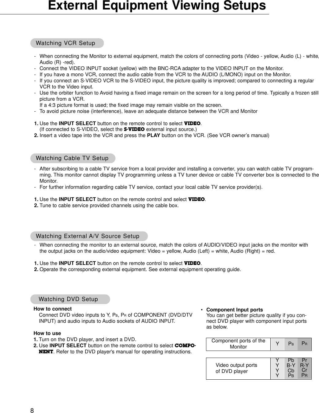
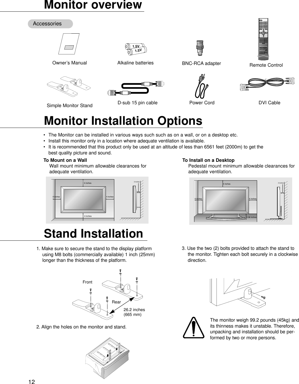
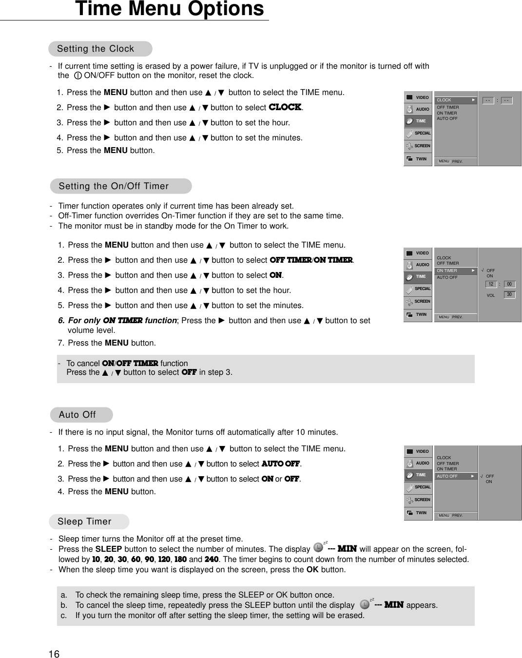
![19Manual Configure (RGB1 [PC] mode only)Manual Configure (RGB1 [PC] mode only)- If the picture isn’t clear after auto adjustment and especially if characters are still jittery, adjust the picture phasemanually.- To correct the screen size, adjust CLOCK.1. Press the MENU button and then use D / Ebutton to select the SCREEN menu.2. Press the Gbutton and then use D / Ebutton to select MANUAL CONFIG..3. Press the Gbutton and then use D / Ebutton to to select PHASE or CLOCK.4. Use the F / Gbutton to make appropriate adjustments.• The adjustment range of PHASE is 0 ~ 31.• The adjustment range of CLOCK is -50 ~ +50.5. Press the MENU button.1. Press the MENU button and then use D / Ebutton to select the SCREEN menu.2. Press the Gbutton and then use D / Ebutton to select RESET.3. Press the Gbutton.•You can initialize ZOOM IN/OUT, POSITION, SPLIT ZOOM, PIP size, PIP position andsub picture size for twin picture.Initializing (Reset to original factory value)Initializing (Reset to original factory value)Screen Screen Adjustments (VIDEO, S-VIDEO and COMPONENTAdjustments (VIDEO, S-VIDEO and COMPONENT 480i mode only)480i mode only)- Use this function to correct jittering or picture instability while viewing a video tape.- This function operates in every mode.- To initialize the adjusted value1. Press the MENU button and then use D /Ebutton to select the SCREEN menu.2. Press the Gbutton and then use D /Ebutton to select SCREEN ADJ..3. Press the Gbutton and then use D /Ebutton to to select TV or VCR.• Select the VCR option if watching a VCR. • Select the TV option for other equipment.(Except VCR)4. Press the MENU button.00VIDEOAUDIOTIMESCREENTWINSPECIALAUTO CONFIG. ARCZOOM IN/OUTPOSITION MANUAL CONFIG.GSCREEN ADJ.RESETPHASE CLOCKMENU PREV.VIDEOAUDIOTIMESCREENTWINSPECIALAUTO CONFIG. ARCZOOM IN/OUTPOSITION MANUAL CONFIG.SCREEN ADJ.RESET GTO SETMENU PREV.VIDEOAUDIOTIMESCREENTWINSPECIALAUTO CONFIG. ARCZOOM IN/OUTPOSITION MANUAL CONFIG.SCREEN ADJ. GRESETTV VCRMENU PREV.- This function works in the following mode:RGB1-PC, RGB1-DTV 480p,720p,1080i, COMPONENT 480p,720p,1080i.1. Press the MENU button and then use D / Ebutton to select the SCREEN menu.2. Press the Gbutton and then use D / Ebutton to select POSITION.3. Press the Gbutton and then use D / E/ F / Gbutton to adjust the position.4. Press the MENU button.◀▶▲▼VIDEOAUDIOTIMESCREENTWINSPECIALAUTO CONFIG. ARCZOOM IN/OUTPOSITION GMANUAL CONFIG.SCREEN ADJ.RESETMENU PREV.Screen PositionScreen Position](https://usermanual.wiki/LG-Electronics-USA/MU50PZ40/User-Guide-264745-Page-19.png)
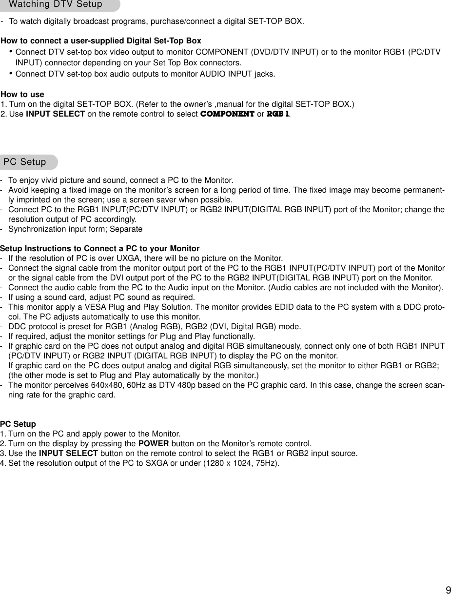
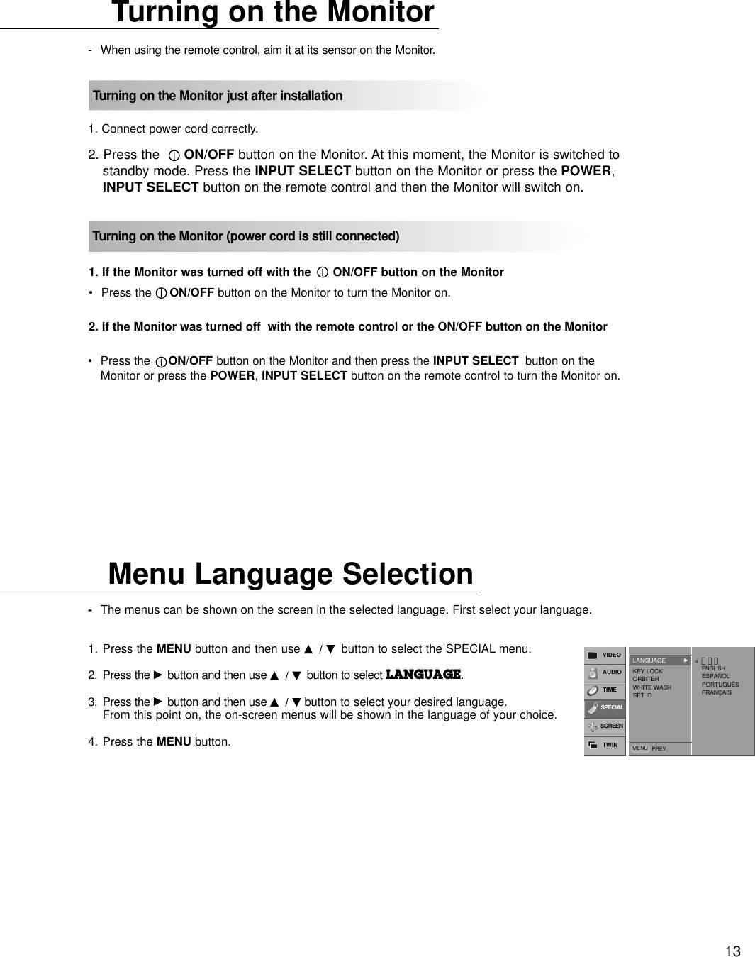
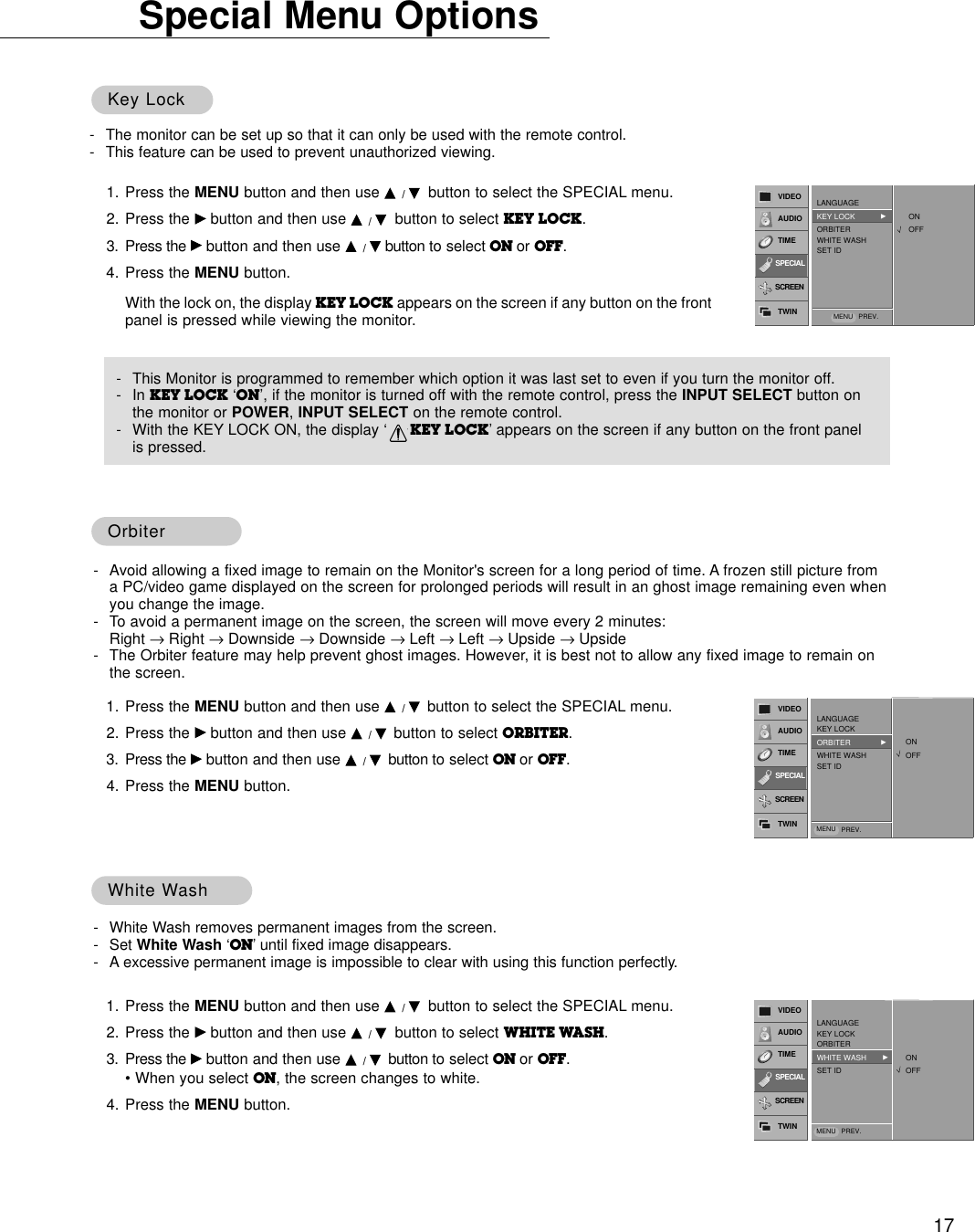
![23Transmission* [Command 1] : k* [Command 2] : To control PDP set.* [Set ID] : You can adjust the set ID to choose desired monitor ID number in special menu. See previous page. Adjustment range is 1 ~ 99. When selecting Set ID ‘0’, every connected PDP set is controlled.* [DATA] : To transmit command data.Transmit ‘FF’data to read status of command.* [Cr] : Carriage ReturnASCII code ‘0x0D’* [ ] : ASCII code ‘space (0x20)’[Command1][Command2][ ][Set ID][ ][Data][Cr]OK Acknowledgement01. Power k a 0 ~ 102. Input Select k b 0 ~ 403. Aspect Ratio k c 0 ~ 204. Screen Mute k d 0 ~ 105. Volume Mute k e 0 ~ 106. Volume Control k f 0 ~ 6407. Contrast k g 0 ~ 6408. Brightness k h 0 ~ 6409. Color k i 0 ~ 6410. Tint k j 0 ~ 6411. Sharpness k k 0 ~ 6412. OSD select k l 0 ~ 113. Remote control lock mode k m 0 ~ 114. PIP/Twin k n 0 ~ 315. PIP size k o 0 ~ 116. PIP position k q 0 ~ 317. Treble k r 0 ~ 6418. Bass k s 0 ~ 6419. Balance k t 0 ~ 6420. Color temperature k u 0 ~ 321. Red adjustment k v 0 ~ 6422. Green adjustment k w 0 ~ 6423. Blue adjustment k $ 0 ~ 6424. PIP input source k y 0 ~ 425. Orbiter j p 0 ~ 126. White Wash j q 0 ~ 127. Orbiter Time Setting j r 1 ~ FE28. Orbiter Pixel Setting j s 0 ~9COMMAND 1 COMMAND 2 DATA(Hexadecimal)* The Monitor transmits ACK (acknowledgement) based onthis format when receiving normal data. At this time, if thedata is data read mode, it indicates present status data. Ifthe data is data write mode, it returns the data of the PCcomputer.[Command2][ ][Set ID][ ][OK][Data][x]Error Acknowledgement* The Monitor transmits ACK (acknowledgement) based onthis format when receiving abnormal data from non-viable functions or communication errors.* When setting the 25 ~ 28, a menu doesn’t display onscreen.[Command2][ ][Set ID][ ][NG][x]TTransmission / Receiving Protocolransmission / Receiving ProtocolCommand Reference ListCommand Reference List02. Input Select (Command:b) (Main Picture Input)GTo select input source for the Monitor. You can also select an input source using the INPUTSELECT button on the Monitor's remote control.TransmissionData 0 : RGB 11 : COMPONENT2 : VIDEO3 : S-VIDEO4 : RGB 2Data 0 : RGB 11 : COMPONENT2 : VIDEO3 : S-VIDEO4 : RGB 2[k][b][ ][Set ID][ ][Data][Cr]Acknowledgement[b][ ][Set ID][ ][OK][Data][x]01. Power (Command:a)GTo control Power On/Off of the Monitor.TransmissionData 0 : Power Off 1 : Power OnData 0 : Power Off 1 : Power On[k][a][ ][Set ID][ ][Data][Cr]Acknowledgement[a][ ][Set ID][ ][OK][Data][x]GTo show Power On/Off.Transmission[k][a][ ][Set ID][ ][FF][Cr]AcknowledgementData 0 : Power Off 1 : Power OnData 0 : Power Off 1 : Power On* In like manner, if other functions transmit ‘FF’data basedon this format, Acknowledgement data feed back presentsstatus about each function.[a][ ][Set ID][ ][OK][Data][x]](https://usermanual.wiki/LG-Electronics-USA/MU50PZ40/User-Guide-264745-Page-23.png)
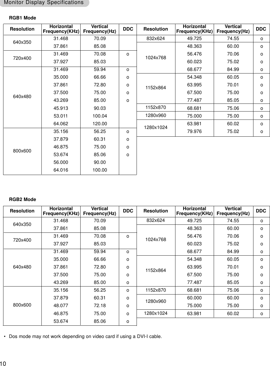
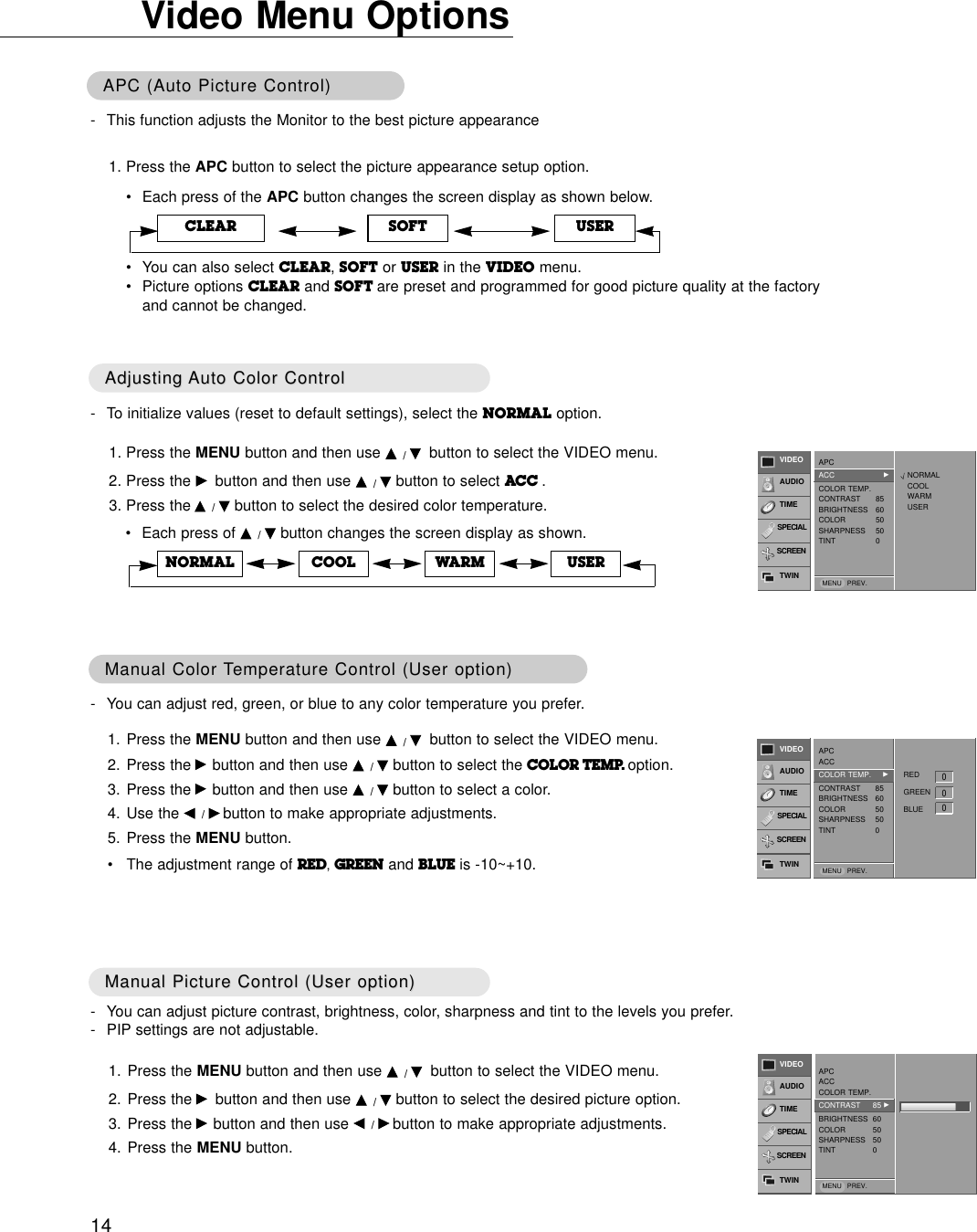
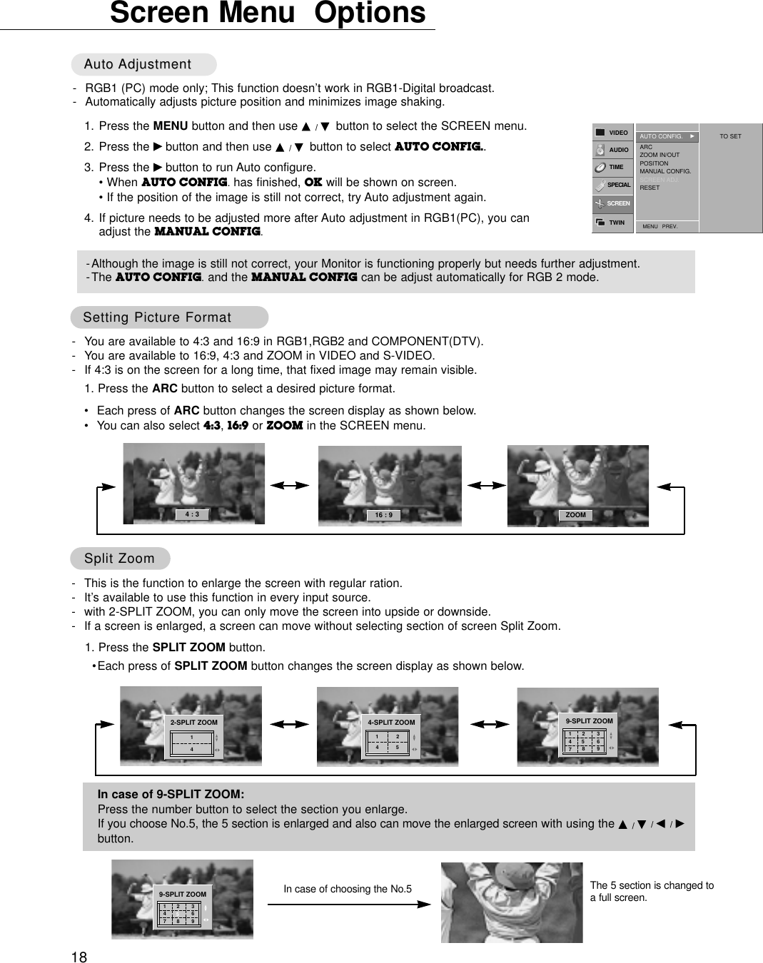
![2409. Color (Command:i)GTo adjust the screen color.You can also adjust color in the Video menu.TransmissionData Min : 0 ~ Max : 64* Refer to ‘Real data mapping1’as shown below.[k][i][ ][Set ID][ ][Data][Cr]AcknowledgementData Min : 0 ~ Max : 64[i][ ][Set ID][ ][OK][Data][x]10. Tint (Command:j)GTo adjust the screen tint.You can also adjust tint in the Video menu.TransmissionData Red : 0 ~ Green : 64* Refer to ‘Real data mapping1’as shown below.[k][j][ ][Set ID][ ][Data][Cr]AcknowledgementData Red : 0 ~ Green : 64[j][ ][Set ID][ ][OK][Data][x]* Real data mapping 10 : Step 0A : Step 10 (SET ID 10)F : Step 15 (SET ID 15)10 : Step 16 (SET ID 16)64 : Step 100* Real data mapping 20 : -105: -9A: -82D: -132: 037: +15F: +964: +1008. Brightness (Command:h)GTo adjust screen brightness.You can also adjust brightness in the Video menu.TransmissionData Min : 0 ~ Max : 64* Refer to ‘Real data mapping1’as shown below.[k][h][ ][Set ID][ ][Data][Cr]AcknowledgementData Min : 0 ~ Max : 64[h][ ][Set ID][ ][OK][Data][x]05. Volume Mute (Command:e)GTo control volume mute on/off.You can also adjust mute using the MUTE button onremote control.TransmissionData 0 : Volume mute on (Volume off)1 : Volume mute off (Volume on)[k][e][ ][Set ID][ ][Data][Cr]AcknowledgementData 0 : Volume mute on (Volume off)1 : Volume mute off (Volume on)[e][ ][Set ID][ ][OK][Data][x]03. Aspect Ratio (Command:c) (Main picture format)GTo adjust the screen format.You can also adjust the screen format using the ARC(Aspect Ratio Control) button on remote control or in theSpecial menu.TransmissionData 0 : Wide screen (16:9)1 : Normal screen (4:3) 2 : Full screen (Zoom) [k][c][ ][Set ID][ ][Data][Cr]AcknowledgementData 0 : Wide screen (16:9)1 : Normal screen (4:3) 2 : Full screen (Zoom) * Using the PC input, you select either 16:9 or 4:3 screenaspect ratio.[c][ ][Set ID][ ][OK][Data][x]04. Screen Mute (Command:d)GTo select screen mute on/off.TransmissionData 0 : Screen mute off (Picture on)1 : Screen mute on (Picture off)[k][d][ ][Set ID][ ][Data][Cr]AcknowledgementData 0 : Screen mute off (Picture on)1 : Screen mute on (Picture off)[d][ ][Set ID][ ][OK][Data][x]06. Volume Control (Command:f)GTo adjust volume.You can also adjust volume with the volume buttonson remote control.TransmissionData Min : 0 ~ Max : 64* Refer to ‘Real data mapping1’as shown right.[k][f][ ][Set ID][ ][Data][Cr]AcknowledgementData Min : 0 ~ Max : 64[f][ ][Set ID][ ][OK][Data][x]07. Contrast (Command:g)GTo adjust screen contrast. You can also adjust contrast in the Video menu.TransmissionData Min : 0 ~ Max : 64* Refer to ‘Real data mapping1’as shown below.[k][g][ ][Set ID][ ][Data][Cr]AcknowledgementData Min : 0 ~ Max : 64[g][ ][Set ID][ ][OK][Data][x]](https://usermanual.wiki/LG-Electronics-USA/MU50PZ40/User-Guide-264745-Page-24.png)
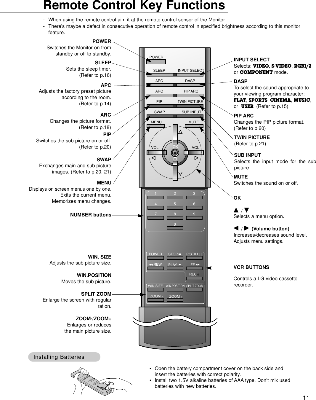
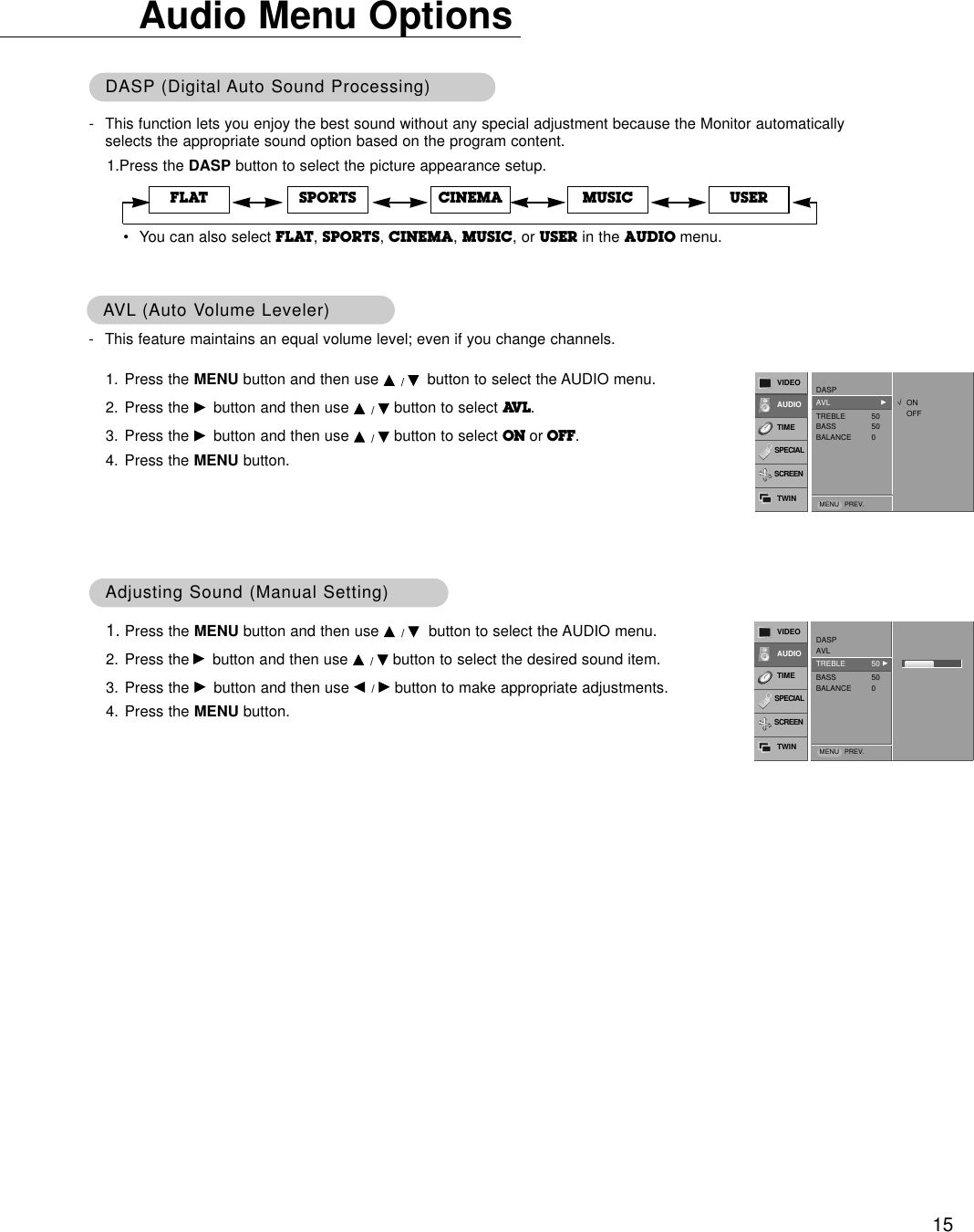
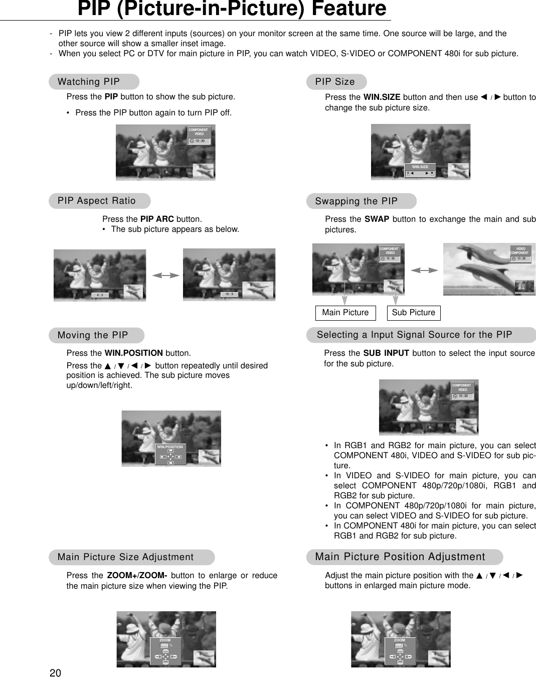
![2517. Treble (Command:r)GTo adjust treble.You can also adjust treble in the Audio menu.TransmissionData Min : 0 ~ Max : 64* Refer to ‘Real data mapping1’. See page 24.[k][r][ ][Set ID][ ][Data][Cr]AcknowledgementData Min : 0 ~ Max : 64[r][ ][Set ID][ ][OK][Data][x]16. PIP Position (Command:q)GTo select sub picture position for PIP. You can also adjust the sub picture position usingWIN.POSITION on the remote control or in the Special menu.TransmissionData 0 : Right down on screen1 : Left down on screen2 : Left up on screen3 : Right up on screen[k][q][ ][Set ID][ ][Data][Cr]AcknowledgementData 0 : Right down on screen1 : Left down on screen2 : Left up on screen3 : Right up on screen[q][ ][Set ID][ ][OK][Data][x]18. Bass (Command:s)GTo adjust bass.You can also adjust bass in the Audio menu.TransmissionData Min : 0 ~ Max : 64* Refer to ‘Real data mapping1’. See page 24.[k][s][ ][Set ID][ ][Data][Cr]AcknowledgementData Min : 0 ~ Max : 64[s][ ][Set ID][ ][OK][Data][x]19. Balance (Command:t)GTo adjust balance.You can also adjust balance in the Audio menu.TransmissionData Min : 0 ~ Max : 64* Refer to ‘Real data mapping1’. See page 24.[k][t][ ][Set ID][ ][Data][Cr]AcknowledgementData Min : 0 ~ Max : 64[t][ ][Set ID][ ][OK][Data][x]13. Remote Control Lock Mode (Command:m)GTo lock the front panel controls on the monitor and remotecontrol.Transmission[k][m][ ][Set ID][ ][Data][Cr]AcknowledgementData 0 : Lock off 1 : Lock onData 0 : Lock off 1 : Lock on* If you’re not using the remote control, use this mode.When main power is on/off, remote control lock is released.[m][ ][Set ID][ ][OK][Data][x]14. PIP / Twin (Command:n)GTo control the PIP (Picture In picture). You can also control the PIP/TWIN using the PIP or Twinpicture button on the remote control or in the Special menu.TransmissionData 0 : PIP/DW off1 : PIP 2 : DW13 : DW2Data 0 : PIP/DW off1 : PIP 2 : DW13 : DW2[k][n][ ][Set ID][ ][Data][Cr]Acknowledgement[n][ ][Set ID][ ][OK][Data][x]GTo adjust the screen sharpness.You can also adjust sharpness in the Video menu.Transmission11. Sharpness (Command:k)Data Min : 0 ~ Max : 64* Refer to ‘Real data mapping1’. See page 24.[k][k][ ][Set ID][ ][Data][Cr]AcknowledgementData Min : 0 ~ Max : 64[k][ ][Set ID][ ][OK][Data][x]12. OSD Select (Command:l)GTo select OSD (On Screen Display) on/off.Transmission[k][l][ ][Set ID][ ][Data][Cr]AcknowledgementData 0 : OSD off 1 : OSD onData 0 : OSD off 1 : OSD on[l][ ][Set ID][ ][OK][Data][x]15. PIP Size (Command:o)GTo select the PIP picture format.You can also select the PIP picture format using WIN.SIZEon the remote control.Transmission[k][o][ ][Set ID][ ][Data][Cr]AcknowledgementData 0 : 4:3 1 : 16:9Data 0 : 4:3 1 : 16:9[o][ ][Set ID][ ][OK][Data][x]](https://usermanual.wiki/LG-Electronics-USA/MU50PZ40/User-Guide-264745-Page-25.png)
![2625. Orbiter (Command:p)GTo control the orbiter function on/off.TransmissionData 0 : Orbiter off1 : Orbiter on[j][p][ ][Set ID][ ][Data][Cr]AcknowledgementData 0 : Orbiter off1 : Orbiter on[p][ ][Set ID][ ][OK][Data][x]26. White Wash (Command:q)GTo control the white wash function on/off.TransmissionData 0 : White Wash off1 : White Wash onData 0 : White Wash off1 : White Wash on[j][q][ ][Set ID][ ][Data][Cr]Acknowledgement[q][ ][Set ID][ ][OK][Data][x]27. Orbiter Time Setting (Command:r)GTo adjust orbiter operation time term.TransmissionData Min : 1 ~ Max : FE* Refer to ‘Real data mapping1’. See page 24.Data Min : 1 ~ Max : FE[j][r][ ][Set ID][ ][Data][Cr]Acknowledgement[r][ ][Set ID][ ][OK][Data][x]28. Orbiter Pixel Setting (Command:s)GTo adjust pixel number in orbiter function.TransmissionData Min : 0 ~ Max : 9* Refer to ‘Real data mapping1’. See page 24.Data Min : 0 ~ Max : 9[j][s][ ][Set ID][ ][Data][Cr]Acknowledgement[s][ ][Set ID][ ][OK][Data][x]21. Red Adjustment (Command:v)GTo adjust red in color temperature.TransmissionData Min : 0 ~ Max : 64* Refer to ‘Real data mapping 2’. See page 24.Data Min : 0 ~ Max : 64[k][v][ ][Set ID][ ][Data][Cr]Acknowledgement[v][ ][Set ID][ ][OK][Data][x]22. Green Adjustment (Command:w)GTo adjust green in color temperature.TransmissionData Min : 0 ~ Max : 64* Refer to ‘Real data mapping 2’. See page 24.Data Min : 0 ~ Max : 64[k][w][ ][Set ID][ ][Data][Cr]Acknowledgement[w][ ][Set ID][ ][OK][Data][x]23. Blue Adjustment (Command:$)GTo adjust blue in color temperature.TransmissionData Min : 0 ~ Max : 64* Refer to ‘Real data mapping 2’. See page 24.Data Min : 0 ~ Max : 64[k][$][ ][Set ID][ ][Data][Cr]Acknowledgement[$][ ][Set ID][ ][OK][Data][x]24. PIP Input Select (Command:y)G To select input source for sub picture in PIP mode.TransmissionData 0 : RGB1 1 : COMPONENT2 : VIDEO 3 : S-VIDEO 4 : RGB2[k][y][ ][Set ID][ ][Data][Cr]AcknowledgementData 0 : RGB1 1 : COMPONENT2 : VIDEO 3 : S-VIDEO 4 : RGB2[y][ ][Set ID][ ][OK][Data][x]20. Color Temperature (Command:u)GTo adjust color temperature.You can also adjust ACC in the Video menu.TransmissionData 0: Normal 1: Cool 2: Warm 3: UserData 0: Normal 1: Cool 2: Warm 3: User[k][u][ ][Set ID][ ][Data][Cr]Acknowledgement[u][ ][Set ID][ ][OK][Data][x]](https://usermanual.wiki/LG-Electronics-USA/MU50PZ40/User-Guide-264745-Page-26.png)