LG Electronics USA MU50PZ90MQ Plasma Monitor User Manual 410Hen 50PZ90MQ
LG Electronics USA Plasma Monitor 410Hen 50PZ90MQ
UserManual.wiki
>
LG Electronics USA
>
MU50PZ90MQ User Manual
User Manual
Navigation menu
Upload a User Manual
Namespaces
Wiki Guide
HTML
PDF
Info
Views
User Manual
Discussion / Help
Navigation
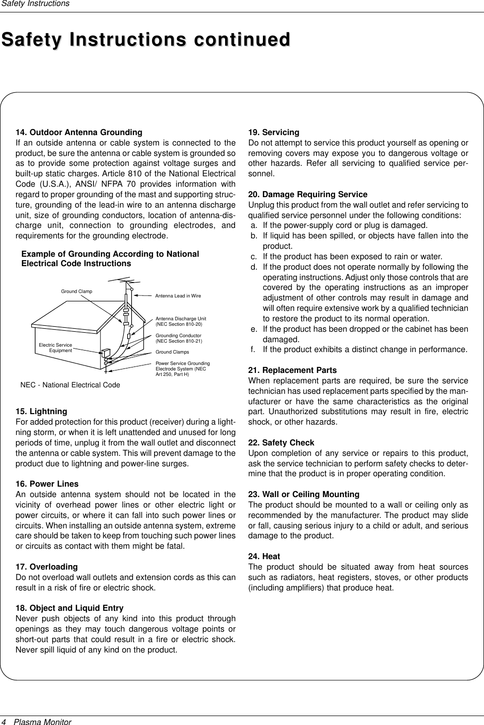
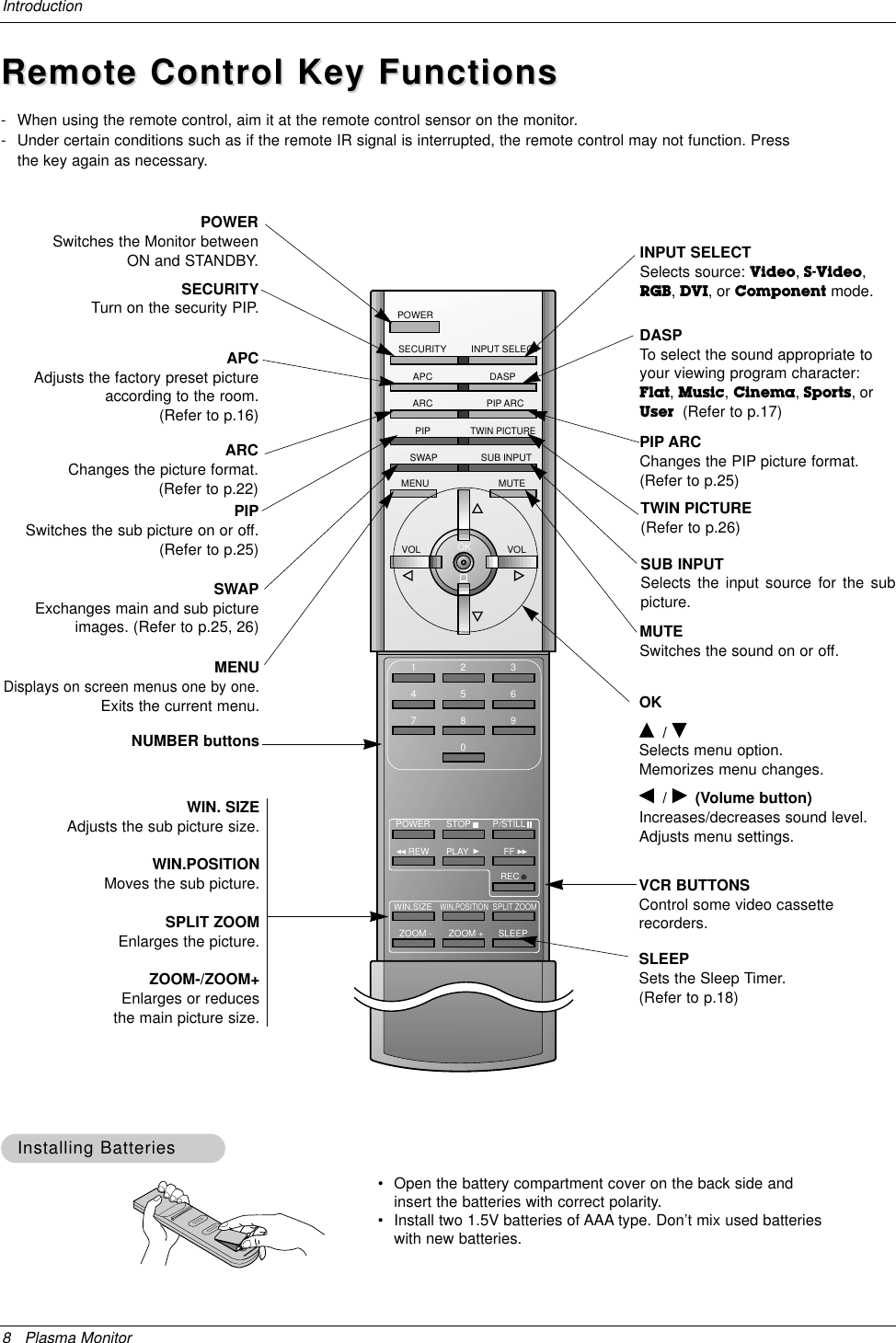
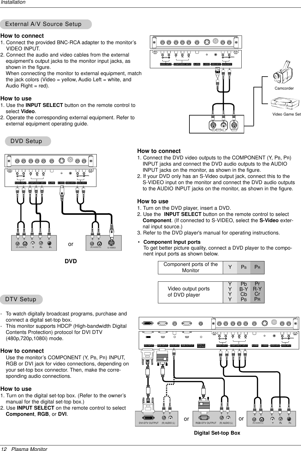
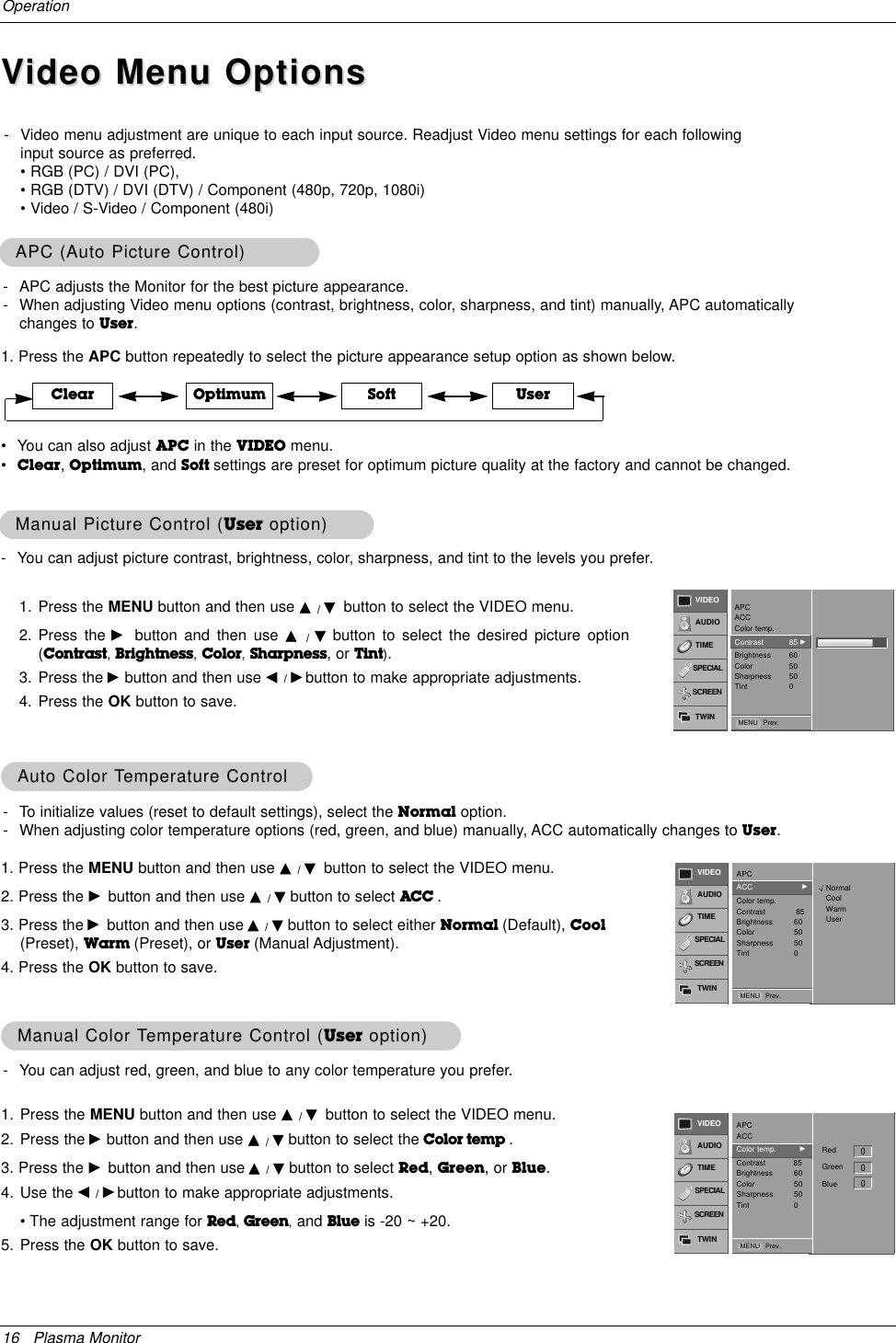
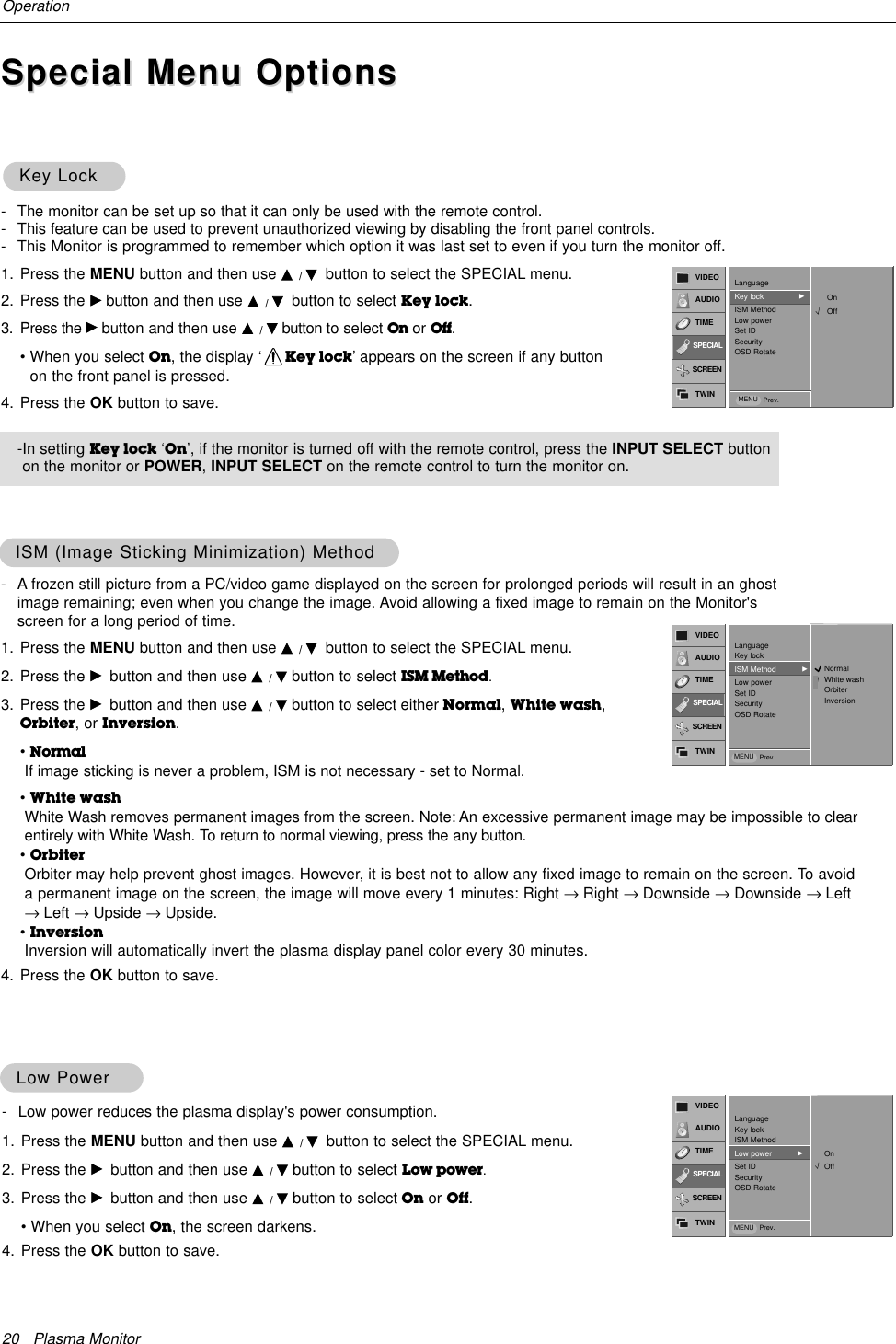
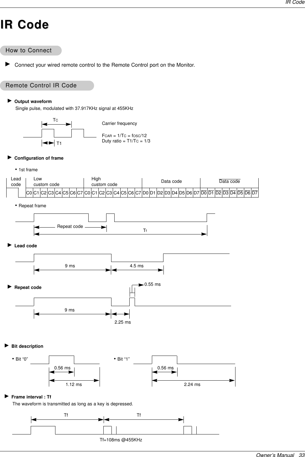
![28 Plasma MonitorExternal Control Device SetupTransmission* [Command 1]: k, j* [Command 2]: To control PDP set.* [Set ID]: You can adjust the set ID to choose desired moni-tor ID number in Special menu. Adjustment rangeis 1 ~ 99. When selecting Set ID ‘0’, every con-nected PDP set is controlled. Set ID is indicatedas decimal (1~99) on menu and as Hexa decimal(0x0~0x63) on transmission/receiving protocol.* [DATA]: To transmit command data.Transmit ‘FF’data to read status of command.* [Cr]: Carriage ReturnASCII code ‘0x0D’* [ ]: ASCII code ‘space (0x20)’[Command1][Command2][ ][Set ID][ ][Data][Cr]OK Acknowledgement* The Monitor transmits ACK (acknowledgement) based onthis format when receiving normal data. At this time, if thedata is data read mode, it indicates present status data. Ifthe data is data write mode, it returns the data of the PCcomputer.[Command2][ ][Set ID][ ][OK][Data][x]Error Acknowledgement* The Monitor transmits ACK (acknowledgement) based onthis format when receiving abnormal data from non-viable functions or communication errors.[Command2][ ][Set ID][ ][NG][x]TTransmission / Receiving Protocolransmission / Receiving Protocol01. Power k a 0 ~ 102. Input Select k b 0 ~ 403. Aspect Ratio k c 0 ~ 304. Screen Mute k d 0 ~ 105. Volume Mute k e 0 ~ 106. Volume Control k f 0 ~ 6407. Contrast k g 0 ~ 6408. Brightness k h 0 ~ 6409. Color k i 0 ~ 6410. Tint k j 0 ~ 6411. Sharpness k k 0 ~ 6412. OSD Select k l 0 ~ 113. Remote Control Lock Mode k m 0 ~ 114. PIP/Twin k n 0 ~ 315. PIP Aspect Ratio k o 0 ~ 116. Split Zoom k p 21 ~9917. PIP Position k q 0 ~ 318. Treble k r 0 ~ 6419. Bass k s 0 ~ 6420. Balance k t 0 ~ 6421. Color Temperature k u 0 ~ 322. Red Adjustment k v 0 ~ C823. Green Adjustment k w 0 ~ C824. Blue Adjustment k $ 0 ~ C825. PIP Input Source k y 0 ~ 426. Abnormal State k z 0 ~ a27. ISM Method j p 0 ~ 328. Low Power j q 0 ~ 129. Orbiter Time Setting j r 1 ~ FE30. Orbiter Pixel Setting j s 0 ~931. Picture Size Setting j t 0 ~64for Twin Picture mode32. Auto Configure j u 1COMMAND 1 COMMAND 2 DATA(Hexadecimal)•Menu doesn’t display on screen when setting the 4,12, 13, and 26 ~ 32.Command Reference ListCommand Reference ListSet IDSet ID- Use this function to specify a monitor ID number.- Refer to ‘Real Data Mapping 1’. See page 29.1. Press the MENU button and then use the D /Ebutton to select the SPECIAL menu.2. Press the Gbutton and then use D /Ebutton to select Set ID.3. Press the Gbutton and then use F / Gbutton to adjust Set ID to choose the desiredmonitor ID number.• The adjustment range of Set ID is 1 ~ 99.1VIDEOAUDIOTIMESCREENTWINSPECIALLanguage Key lockISM Method Low powerSet ID GSecurityOSD RotateMENU Prev.• Baud rate : 115200 bps (UART)• Data length : 8 bits• Parity : None• Stop bit : 1 bit• Communication code : ASCII codeCommunication ParametersCommunication ParametersData 1: Illegal Code2: Not supported function3: Wait more time](https://usermanual.wiki/LG-Electronics-USA/MU50PZ90MQ/User-Guide-371173-Page-28.png)
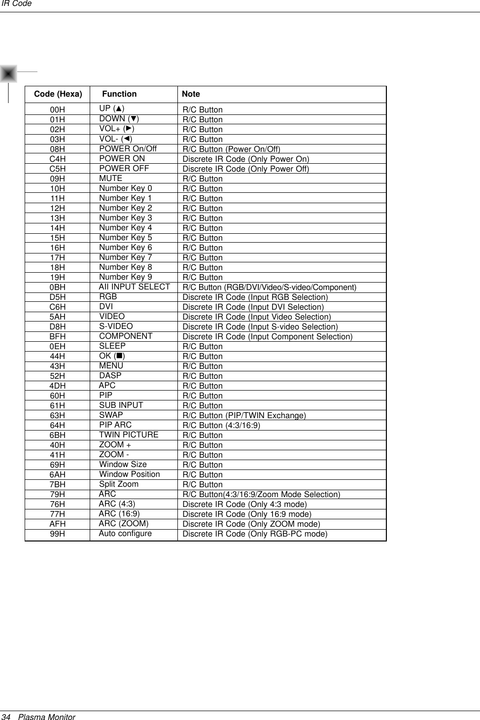
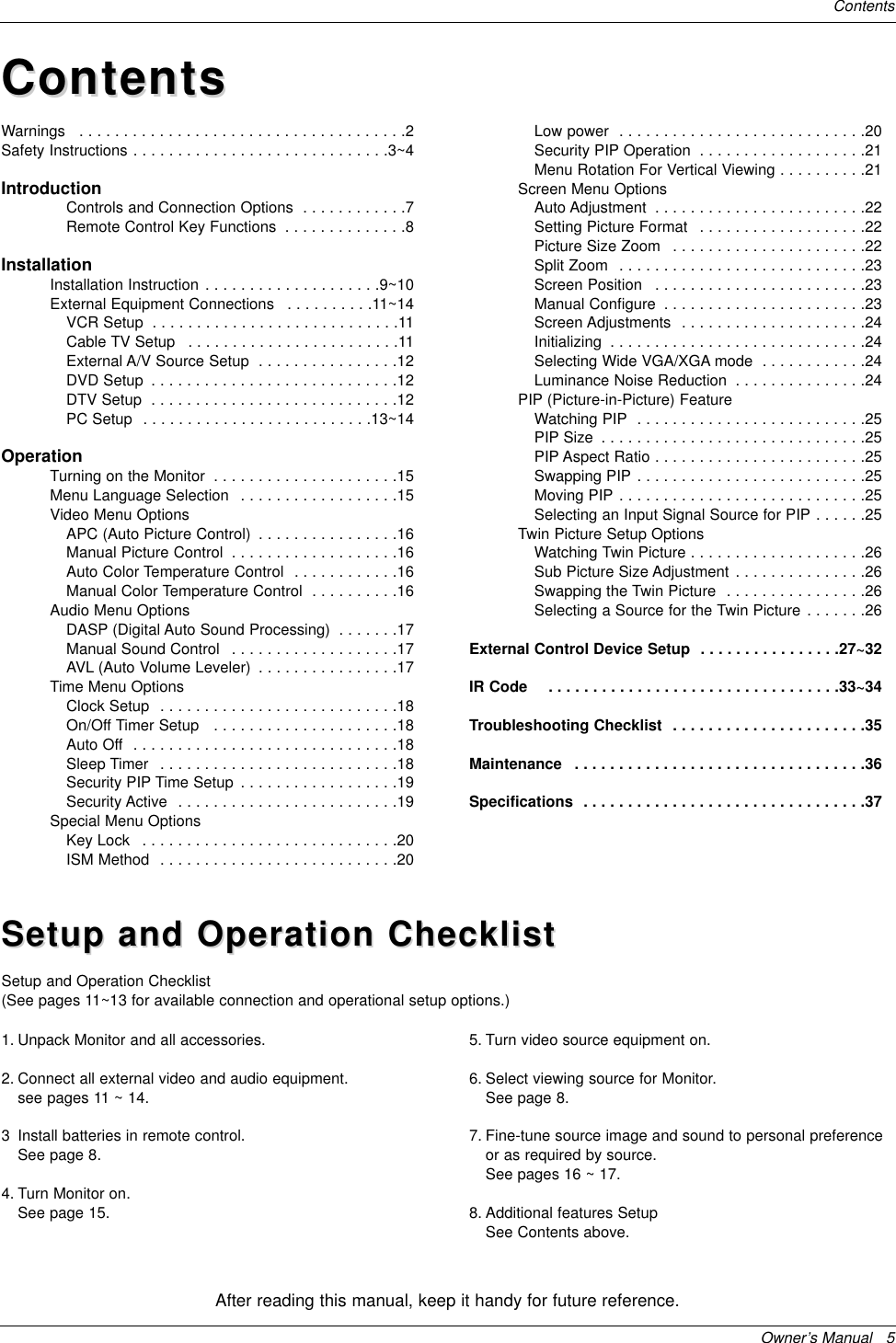
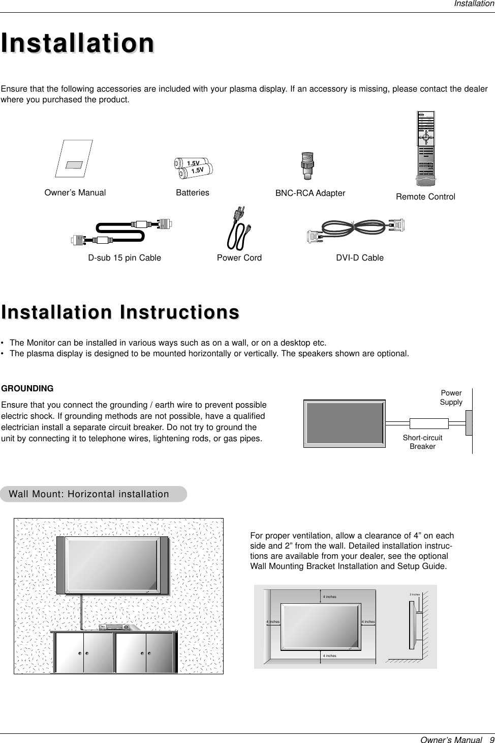
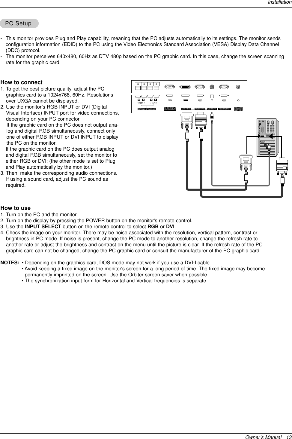
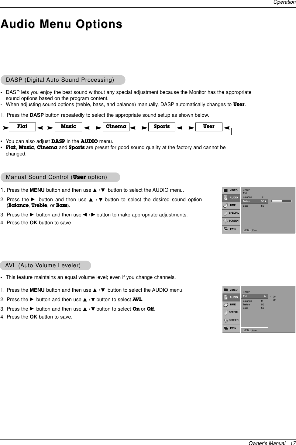
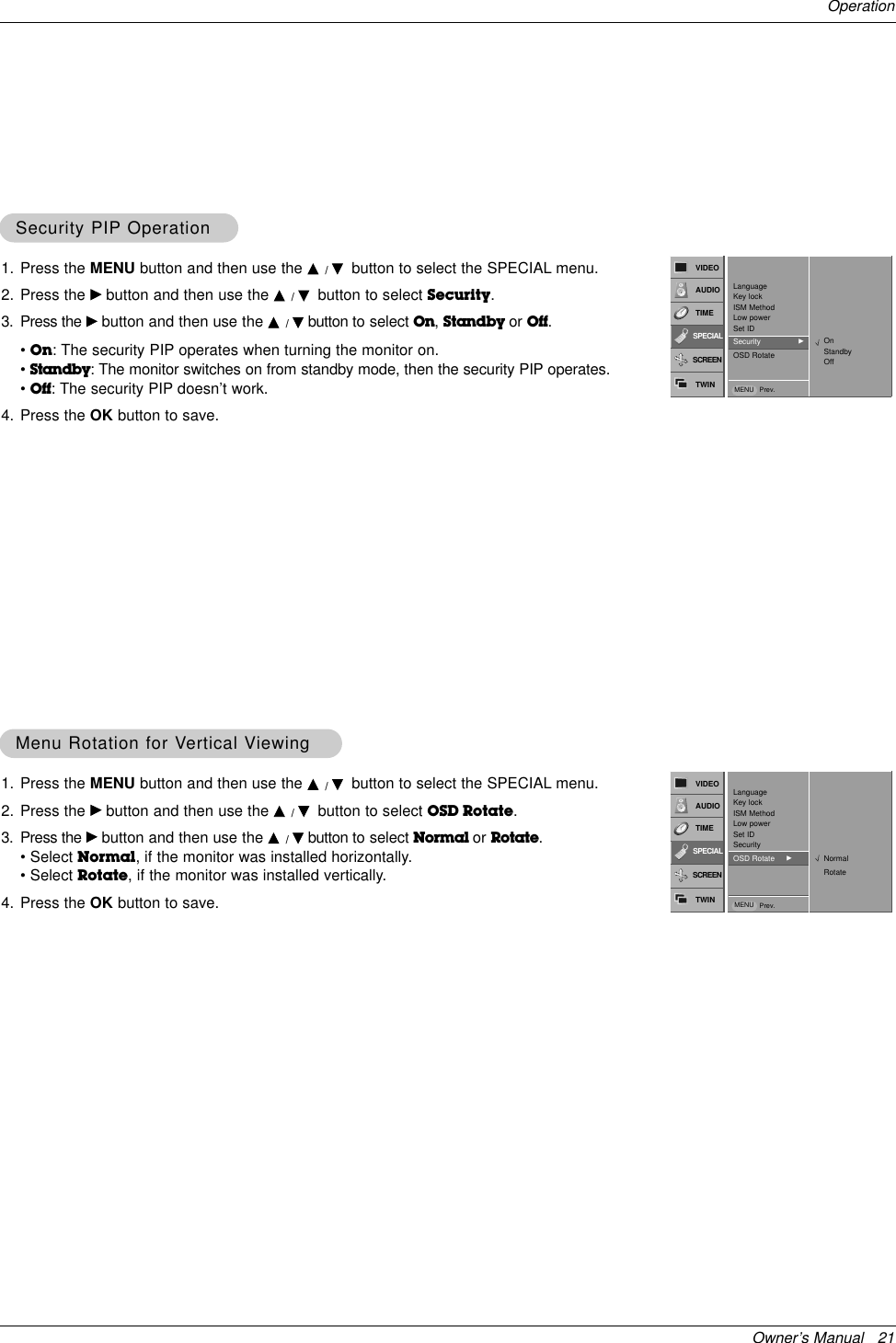
![Owner’s Manual 29External Control Device Setup02. Input Select (Command2:b) (Main Picture Input)GTo select input source for the Monitor. You can also select an input source using the INPUTSELECT button on the Monitor's remote control.TransmissionData 0 : RGB1 : Component2 : Video3 : S-video4 : DVI[k][b][ ][Set ID][ ][Data][Cr]Acknowledgement[b][ ][Set ID][ ][OK][Data][x]01. Power (Command2:a)GTo control Power On/Off of the Monitor.TransmissionData 0 : Power Off 1 : Power On[k][a][ ][Set ID][ ][Data][Cr]Acknowledgement[a][ ][Set ID][ ][OK][Data][x]GTo show Power On/Off.Transmission[k][a][ ][Set ID][ ][FF][Cr]AcknowledgementData 0 : Power Off 1 : Power On* In a like manner, if other functions transmit ‘FF’databased on this format, Acknowledgement data feedbackpresents status about each function.[a][ ][Set ID][ ][OK][Data][x]03. Aspect Ratio (Command2:c) (Main picture format)GTo adjust the screen format.You can also adjust the screen format using the ARC(Aspect Ratio Control) button on remote control or in theSpecial menu.TransmissionData 0 : Wide screen (16:9)1 : Normal screen (4:3) 2 : Full screen (Zoom) 3 : Horizon[k][c][ ][Set ID][ ][Data][Cr]Acknowledgement* You select either 16:9 or 4:3 screen aspect ratio using thePC, DTV 720p/1080i. [c][ ][Set ID][ ][OK][Data][x]05. Volume Mute (Command2:e)GTo control volume mute on/off.You can also adjust mute using the MUTE button onremote control.TransmissionData 0 : Volume mute on (Volume off)1 : Volume mute off (Volume on)[k][e][ ][Set ID][ ][Data][Cr]Acknowledgement[e][ ][Set ID][ ][OK][Data][x]04. Screen Mute (Command2:d)GTo select screen mute on/off.TransmissionData 0 : Screen mute off (Picture on)1 : Screen mute on (Picture off)[k][d][ ][Set ID][ ][Data][Cr]Acknowledgement[d][ ][Set ID][ ][OK][Data][x]06. Volume Control (Command2:f)GTo adjust volume.You can also adjust volume with the volume buttonson remote control.TransmissionData Min : 0 ~ Max : 64•Refer to ‘Real data mapping1’as shown below.[k][f][ ][Set ID][ ][Data][Cr]Acknowledgement[f][ ][Set ID][ ][OK][Data][x]07. Contrast (Command2:g)GTo adjust screen contrast. You can also adjust contrast in the Video menu.TransmissionData Min : 0 ~ Max : 64•Refer to ‘Real data mapping1’as shown below.[k][g][ ][Set ID][ ][Data][Cr]Acknowledgement[g][ ][Set ID][ ][OK][Data][x]* Real data mapping 10 : Step 0A : Step 10 (SET ID 10)F : Step 15 (SET ID 15)10 : Step 16 (SET ID 16)64 : Step 100](https://usermanual.wiki/LG-Electronics-USA/MU50PZ90MQ/User-Guide-371173-Page-29.png)
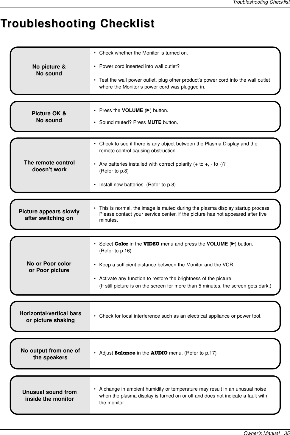
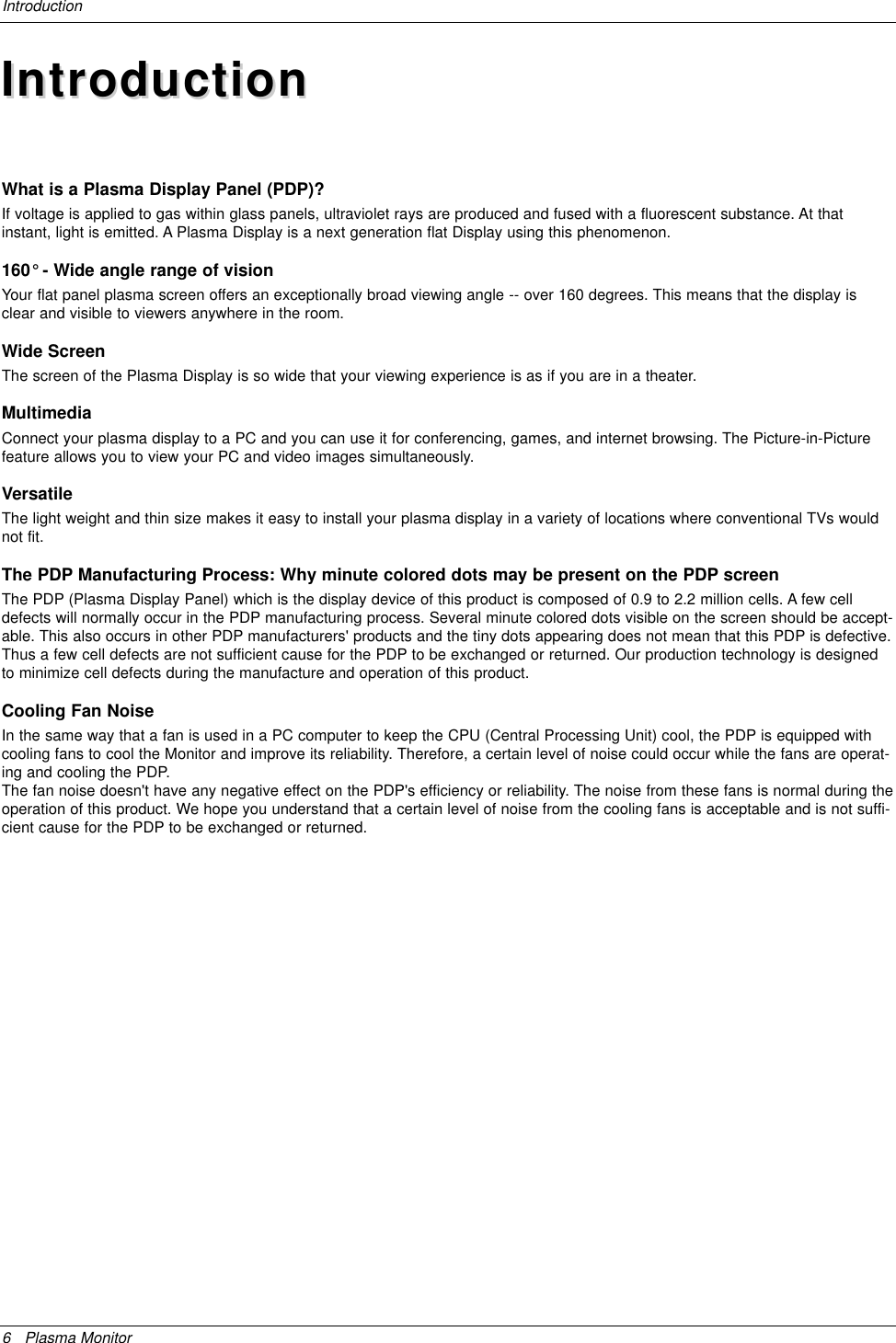
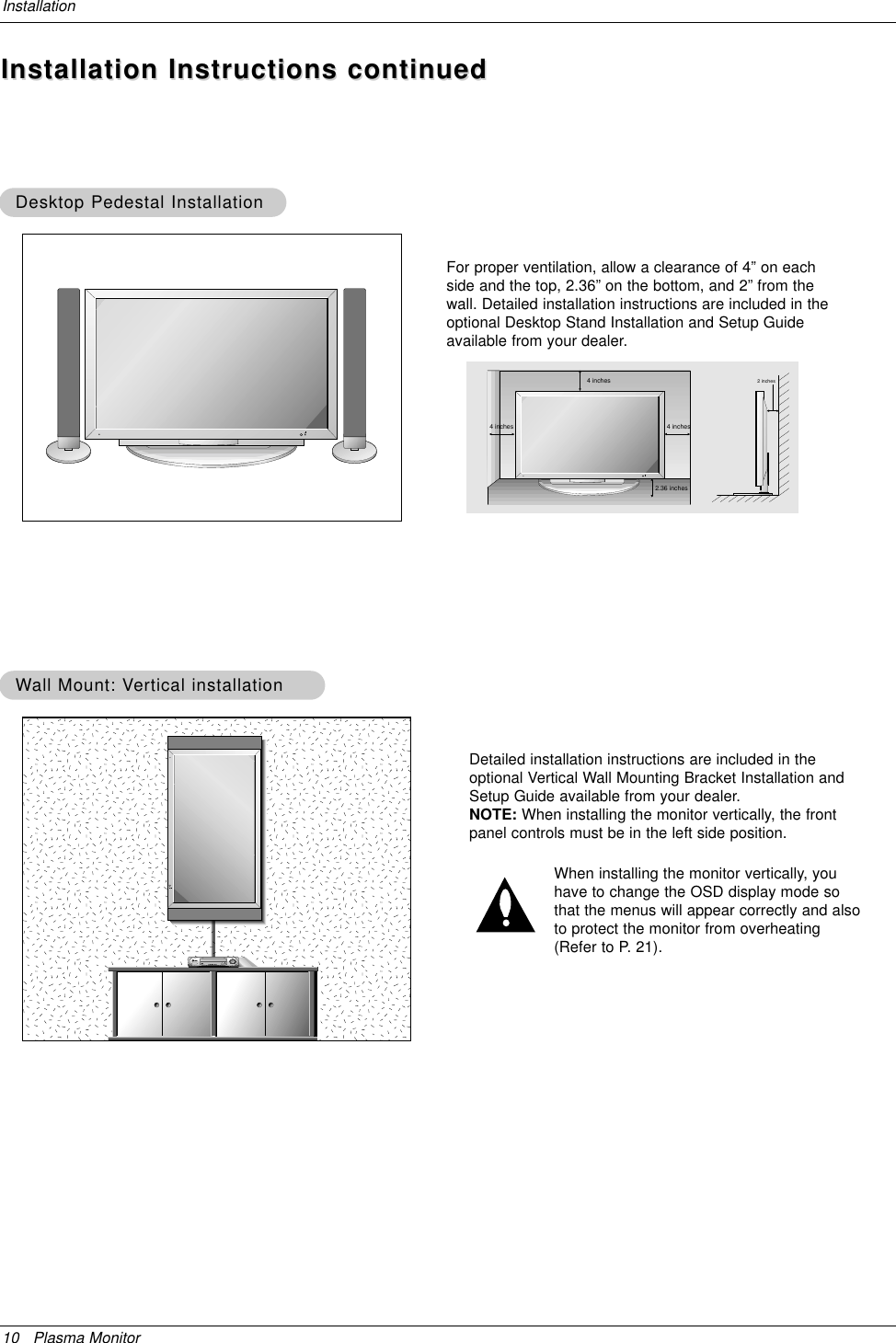
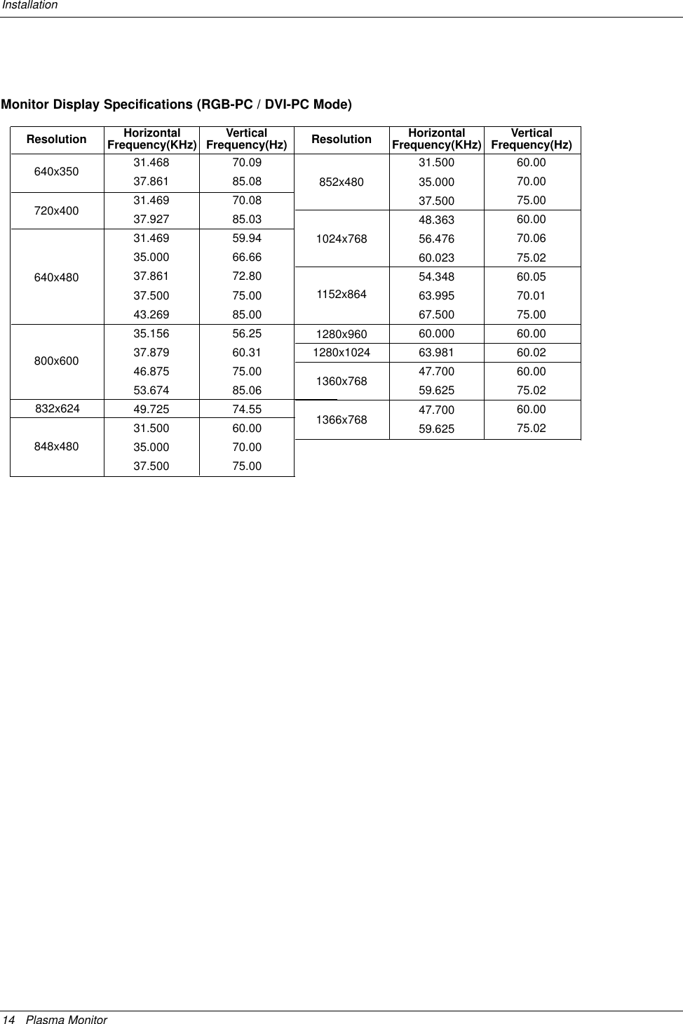
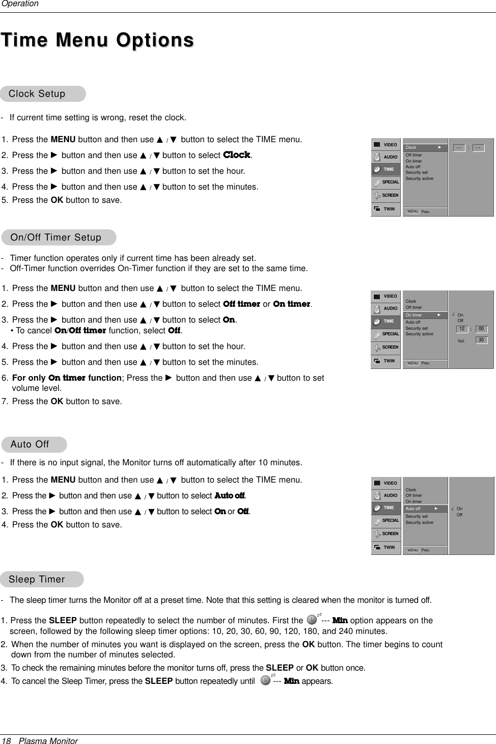
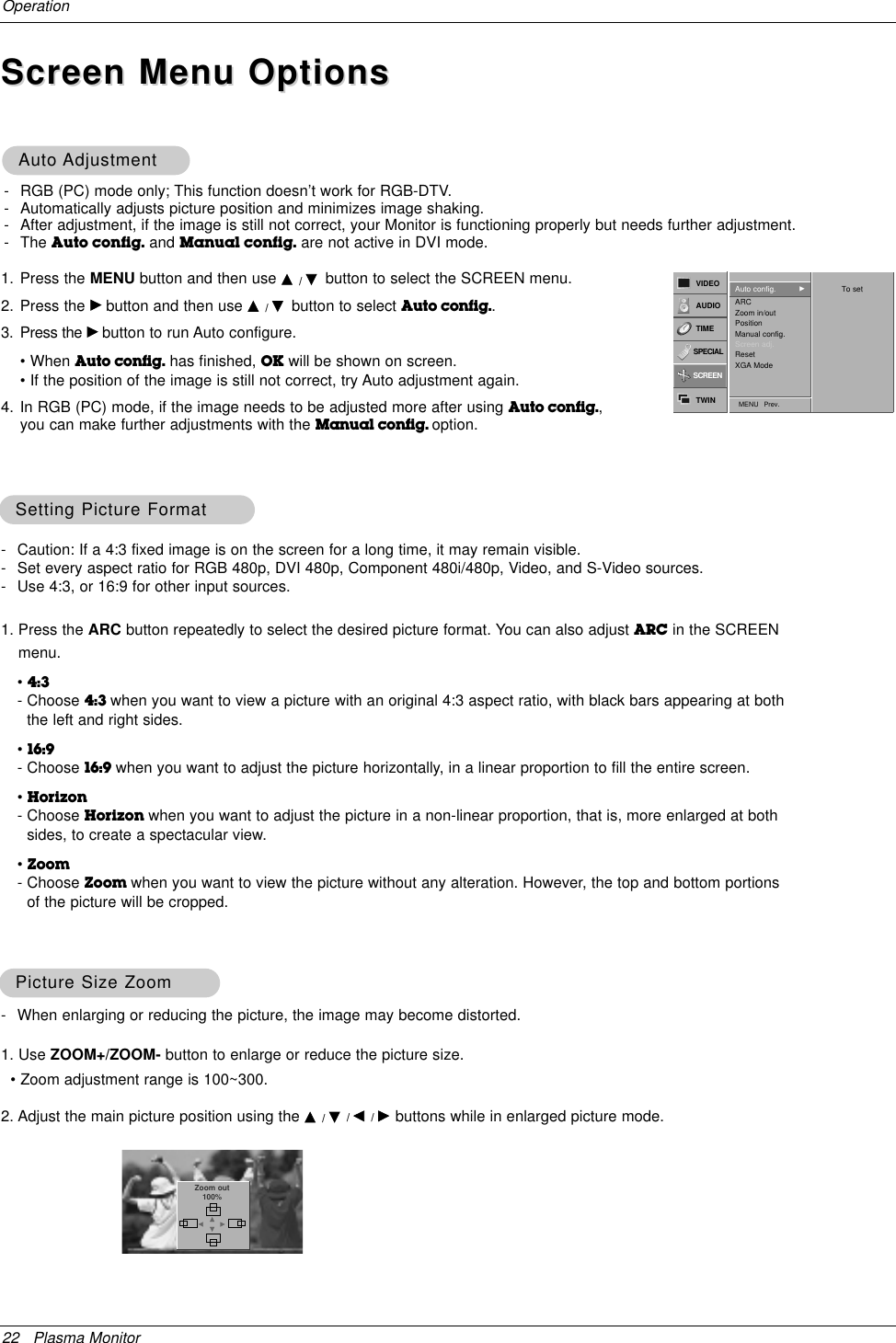
![30 Plasma MonitorExternal Control Device Setup13. Remote Control Lock Mode (Command2:m)GTo lock the remote control and front panel controls on themonitorTransmission[k][m][ ][Set ID][ ][Data][Cr]AcknowledgementData 0: Lock off 1: Lock on•If you’re not using the remote control and front panel con-trols on the monitor, use this mode. When main power ison/off, remote control lock is released.[m][ ][Set ID][ ][OK][Data][x]14. PIP / Twin (Command2:n)GTo control the PIP (Picture-in-Picture) or Twin Picture. You can also control the PIP/Twin picture mode using the PIPor TWIN PICTURE button on the remote control or in theTwin menu.TransmissionData 0: PIP/DW off1: PIP 2: DW13: DW2[k][n][ ][Set ID][ ][Data][Cr]Acknowledgement[n][ ][Set ID][ ][OK][Data][x]GTo adjust the screen sharpness.You can also adjust sharpness in the Video menu.Transmission11. Sharpness (Command2:k)Data Min: 0 ~ Max: 64•Refer to ‘Real data mapping 1’. See page 29.[k][k][ ][Set ID][ ][Data][Cr]Acknowledgement[k][ ][Set ID][ ][OK][Data][x]12. OSD Select (Command2:l)GTo select OSD (On Screen Display) on/off.Transmission[k][l][ ][Set ID][ ][Data][Cr]AcknowledgementData 0: OSD off 1: OSD on[l][ ][Set ID][ ][OK][Data][x]15. PIP Aspect Ratio (Command2:o)GTo select the PIP picture format.You can also select the PIP picture format using PIP ARCon the remote control.Transmission[k][o][ ][Set ID][ ][Data][Cr]AcknowledgementData 0: 4:3 1: 16:9[o][ ][Set ID][ ][OK][Data][x]09. Color (Command2:i)GTo adjust the screen color.You can also adjust color in the Video menu.TransmissionData Min : 0 ~ Max : 64•Refer to ‘Real data mapping 1’. See page 29.[k][i][ ][Set ID][ ][Data][Cr]Acknowledgement[i][ ][Set ID][ ][OK][Data][x]10. Tint (Command2:j)GTo adjust the screen tint.You can also adjust tint in the Video menu.TransmissionData Red : 0 ~ Green : 64•Refer to ‘Real data mapping 1’. See page 29.[k][j][ ][Set ID][ ][Data][Cr]Acknowledgement[j][ ][Set ID][ ][OK][Data][x]08. Brightness (Command2:h)GTo adjust screen brightness.You can also adjust brightness in the Video menu.TransmissionData Min : 0 ~ Max : 64•Refer to ‘Real data mapping 1’. See page 29.[k][h][ ][Set ID][ ][Data][Cr]Acknowledgement[h][ ][Set ID][ ][OK][Data][x]16. Split Zoom (Command2:p)GTo operate split zoom function and select the splitzoom section number.TransmissionData Min: 21 ~ Max: 99•Refer to ‘Real data mapping 2’.[k][p][ ][Set ID][ ][Data][Cr]Acknowledgement[p][ ][Set ID][ ][OK][Data][x]* Real data mapping 221: Selection 1 of 2 split zoom24: Selection 4 of 2 split zoom41: Selection 1 of 4 split zoom42: Selection 2 of 4 split zoom44: Selection 4 of 4 split zoom45: Selection 5 of 4 split zoom91: Selection 1 of 9 split zoom99: Selection 9 of 9 split zoom](https://usermanual.wiki/LG-Electronics-USA/MU50PZ90MQ/User-Guide-371173-Page-30.png)
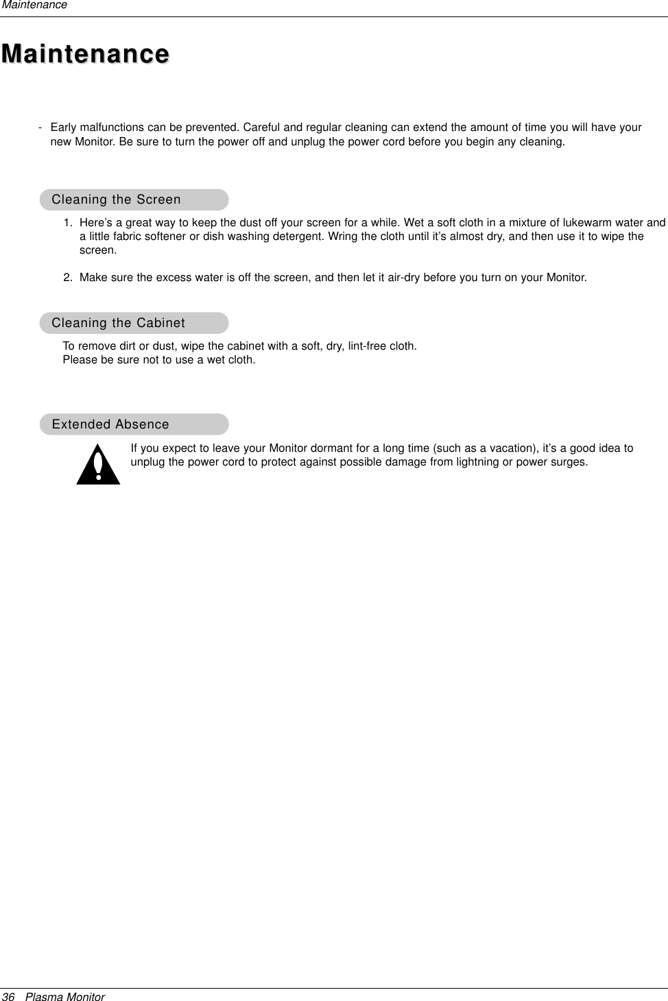
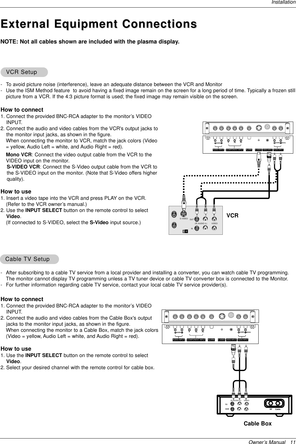
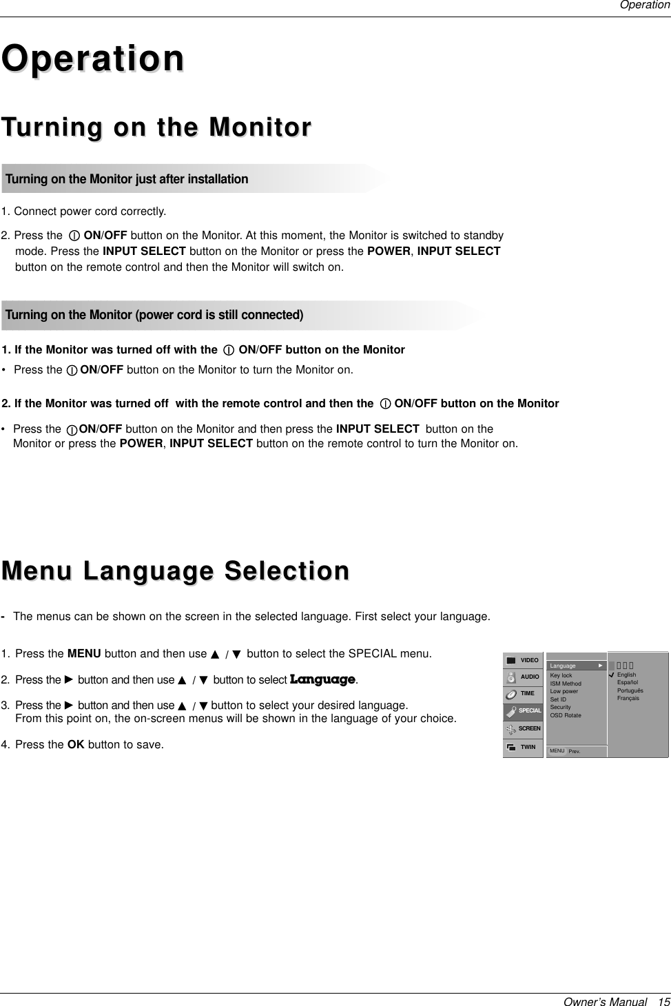
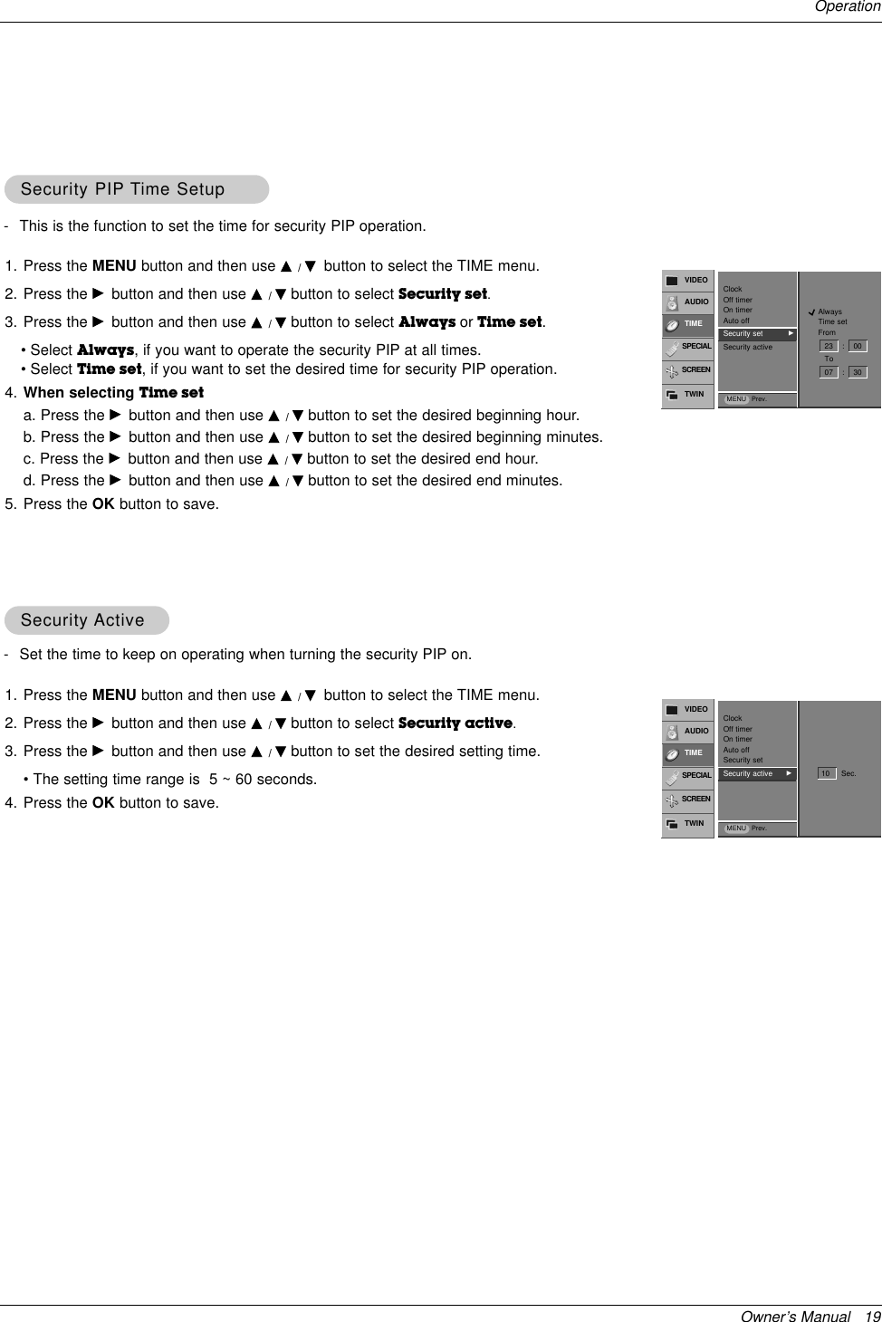
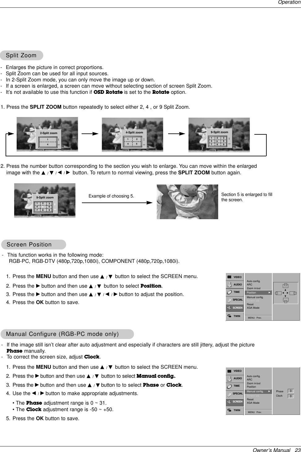
![Owner’s Manual 31External Control Device Setup21. Color Temperature (Command2:u)GTo adjust color temperature.You can also adjust ACC in the Video menu.TransmissionData 0: Normal 1: Cool 2: Warm 3: User[k][u][ ][Set ID][ ][Data][Cr]Acknowledgement[u][ ][Set ID][ ][OK][Data][x]18. Treble (Command2:r)GTo adjust treble.You can also adjust treble in the Audio menu.TransmissionData Min: 0 ~ Max: 64•Refer to ‘Real data mapping 1’. See page 29.[k][r][ ][Set ID][ ][Data][Cr]Acknowledgement[r][ ][Set ID][ ][OK][Data][x]17. PIP Position (Command2:q)GTo select sub picture position for PIP. You can also adjust the sub picture position usingWin.position on the remote control or in the Twin menu.TransmissionData 0: Right down on screen1: Left down on screen2: Left up on screen3: Right up on screen[k][q][ ][Set ID][ ][Data][Cr]Acknowledgement[q][ ][Set ID][ ][OK][Data][x]19. Bass (Command2:s)GTo adjust bass.You can also adjust bass in the Audio menu.TransmissionData Min: 0 ~ Max: 64•Refer to ‘Real data mapping 1’. See page 29.[k][s][ ][Set ID][ ][Data][Cr]Acknowledgement[s][ ][Set ID][ ][OK][Data][x]20. Balance (Command2:t)GTo adjust balance.You can also adjust balance in the Audio menu.TransmissionData Min: 0 ~ Max: 64•Refer to ‘Real data mapping 1’. See page 29.[k][t][ ][Set ID][ ][Data][Cr]Acknowledgement[t][ ][Set ID][ ][OK][Data][x]* Real data mapping 30 : -205 : -19A : -185F: -164: 069: +1C3: +19C8: +2022. Red Adjustment (Command2:v)GTo adjust red in color temperature.TransmissionData Min: 0 ~ Max: C8•Refer to ‘Real data mapping 3’as shown below.[k][v][ ][Set ID][ ][Data][Cr]Acknowledgement[v][ ][Set ID][ ][OK][Data][x]23. Green Adjustment (Command2:w)GTo adjust green in color temperature.TransmissionData Min: 0 ~ Max: C8•Refer to ‘Real data mapping 3’as shown below.[k][w][ ][Set ID][ ][Data][Cr]Acknowledgement[w][ ][Set ID][ ][OK][Data][x]24. Blue Adjustment (Command2:$)GTo adjust blue in color temperature.TransmissionData Min: 0 ~ Max: C8•Refer to ‘Real data mapping 3’as shown below.[k][$][ ][Set ID][ ][Data][Cr]Acknowledgement[$][ ][Set ID][ ][OK][Data][x]](https://usermanual.wiki/LG-Electronics-USA/MU50PZ90MQ/User-Guide-371173-Page-31.png)
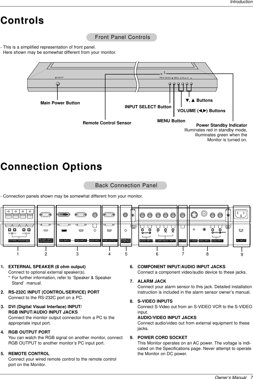
![32 Plasma MonitorExternal Control Device Setup27. ISM Method (Command2:p)GTo avoid having a fixed image remain on screen.TransmissionData 0: Normal1: White wash 2: Orbiter3: Inversion[j][p][ ][Set ID][ ][Data][Cr]Acknowledgement[p][ ][Set ID][ ][OK][Data][x]28. Low Power (Command2:q)GTo control the low power function on/off.TransmissionData 0: Low power off1: Low power on[j][q][ ][Set ID][ ][Data][Cr]Acknowledgement[q][ ][Set ID][ ][OK][Data][x]29. Orbiter Time Setting (Command2:r)GTo adjust orbiter operation time term.TransmissionData Min: 1 ~ Max: FE[j][r][ ][Set ID][ ][Data][Cr]Acknowledgement[r][ ][Set ID][ ][OK][Data][x]30. Orbiter Pixel Setting (Command2:s)GTo adjust pixel number in orbiter function.TransmissionData Min: 0 ~ Max: 9[j][s][ ][Set ID][ ][Data][Cr]Acknowledgement[s][ ][Set ID][ ][OK][Data][x]32. Auto Configure (Command2:u)GTo adjust picture position and minimize image shakingautomatically. Auto Configure only works in RGB-PCmode.TransmissionData 1: To set[j][u][ ][Set ID][ ][Data][Cr]Acknowledgement[u][ ][Set ID][ ][OK][Data][x]31. Picture Size Setting for Twin Picture mode(Command2:t)GTo adjust main picture size in twin picture mode.TransmissionData Min: 0 ~ Max: 64•Refer to ‘Real data mapping1’. See page 29.[j][t][ ][Set ID][ ][Data][Cr]Acknowledgement[t][ ][Set ID][ ][OK][Data][x]25. PIP Input Select (Command2:y)G To select input source for sub picture in PIP mode.TransmissionData 0: RGB 1: Component2: Video 3: S-video 4: DVI[k][y][ ][Set ID][ ][Data][Cr]Acknowledgement[y][ ][Set ID][ ][OK][Data][x]26. Abnormal State (Command2:z)GTo recognize an abnormal state.TransmissionData 0: Normal (Power on and signal exist)1: No signal (Power on)2: Turn the monitor off by remote control3: Turn the monitor off by sleep time function4: Turn the monitor off by RS-232C function5: 5V down6: AC down7: Turn the monitor off by Fan Alarm function8: Turn the monitor off by off time function9: Turn the monitor off by auto off functiona: Turn the monitor off by AV board detect[k][z][ ][Set ID][ ][FF][Cr]Acknowledgement[z][ ][Set ID][ ][OK][Data][x]Data FF:Read](https://usermanual.wiki/LG-Electronics-USA/MU50PZ90MQ/User-Guide-371173-Page-32.png)