LG Electronics USA WB1NP7 Bluetooth Module User Manual
LG Electronics USA Bluetooth Module
UserManual.wiki
>
LG Electronics USA
>
WB1NP7 User Manual
User manual
Navigation menu
Upload a User Manual
Namespaces
Wiki Guide
HTML
PDF
Info
Views
User Manual
Discussion / Help
Navigation
![1. Module : WB1NP7 [Top] [Bottom] This WB1NP7 Module can be easily designed into any embedded system for Bluetooth Spec 4.2 feature. It is based on Airoha’s AB1520 with specific interface design to meet LG Electronics’s needs. 2. Module SpecificationChips AB1520 Bluetooth Spec Bluetooth 4.2 Frequency Band 2402 ~ 2480 MHz Tx Power 0.25 ~ 2.5mW (Bluetooth Power Class I) Rx Sensitivity < -70dBm (BER 0.1%) Distance < 100m (Open Space) Power Voltage 3.7V Dimension 20mmⅹ26mm ⅹ3.1 mm Environmental Range Operation temperature -10 ~ 50℃Modulation GFSK, 8DPSK, π/4-DQPSK Communication Method FHSS](https://usermanual.wiki/LG-Electronics-USA/WB1NP7/User-Guide-3263383-Page-1.png)
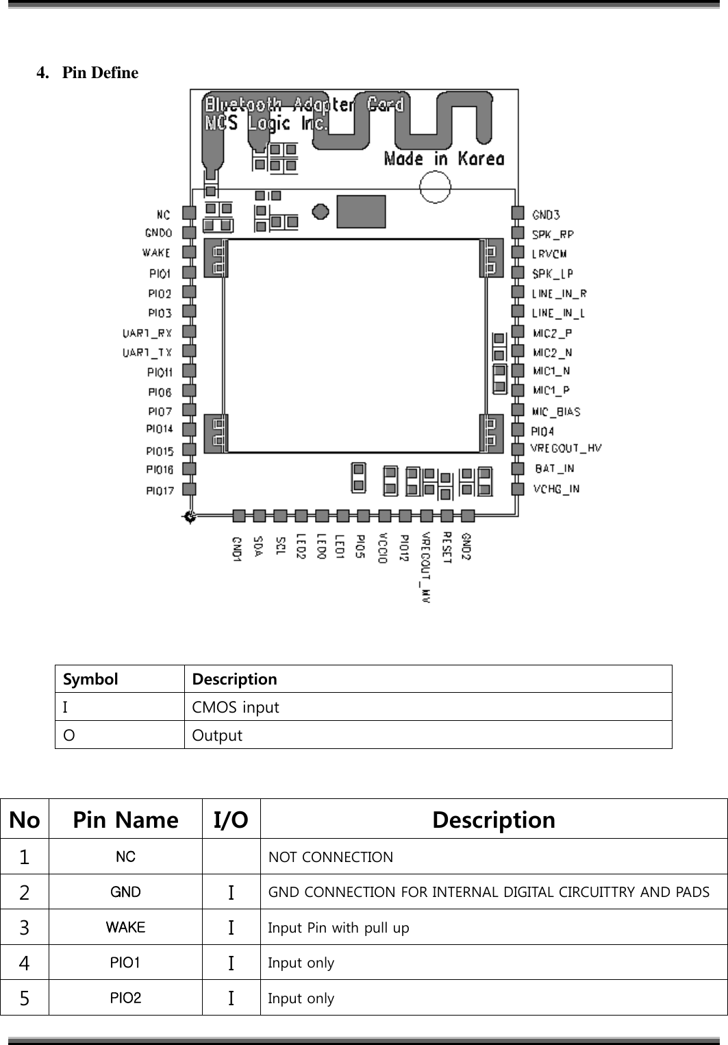
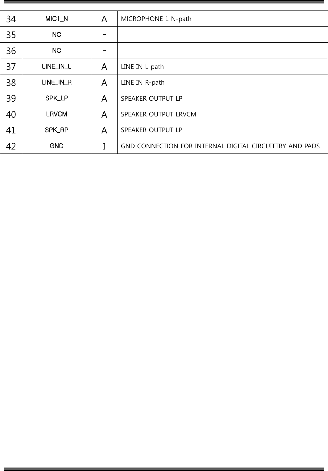
![6 PIO3 I/OI2S_SDI2, Alternative function PIO[3] 7 UART_RX IUART DATA IN 8 UART_TX OUART DATA OUT 9 PIO11 I/OAIO and I2S_SDI, Alternative function PIO[11] 10 PIO6 I/OI2S_MCLK, Alternative function PIO[6] 11 PIO7 I/OI2S_SCK, Alternative function PIO[7] 12 PIO14 I/OI2S_WS, Alternative function PIO[14] 13 PIO15 I/OI2S_SDO, Alternative function PIO[15] 14 PIO16 I/OI2S_MCLK2, Alternative function PIO[16] 15 PIO17 I/OI2S_SCK2, Alternative function PIO[17] 16 GND IGND CONNECTION FOR INTERNAL DIGITAL CIRCUITTRY AND PADS 17 SDA I/OI2C DATA LINE 18 SCL I/OI2C CLOCK LINE 19 LED2 OLED DRIVER (OPEN DRAIN) 20 LED0 OLED DRIVER (OPEN DRAIN) 21 LED1 OLED DRIVER (OPEN DRAIN) 22 PIO5 II2S_SDO2, Alternative function PIO[5] 23 VCCIO I1.7~3.6V SUPPLY INPUT FOR PIO 24 PIO12 I/OAIO, Alternative function PIO[17] 25 VREGOUT_MV OLDO OUT(1V8) 26 RESET IGOLBAL RESET, ACTIVE HIGH 27 GND IGND CONNECTION FOR INTERNAL DIGITAL CIRCUITTRY AND PADS 28 VCHG_IN IVCC FOR CHARGER 29 BAT_IN IBattery input P 30 VREGOUT_HV OLDO OUT(3V3) 31 PIO4 OI2S_WS2, Alternative function PIO[4] 32 MIC_BIAS AMICROPHONE 1 Bias 33 MIC1_P AMICROPHONE 1 P-path](https://usermanual.wiki/LG-Electronics-USA/WB1NP7/User-Guide-3263383-Page-3.png)