LG Electronics USA ZA-P20 ZigBee Adapter User Manual
LG Electronics USA ZigBee Adapter Users Manual
Users Manual

Written Date
2011-03-24
Doc No
Version
1.0
Writer
Do Geun Chang
Examination
Approval
Bang Jun Wan
Doc Manager
Subject
ZA-P20 RF TEST MANUAL
Doc Class
Test Manual
KQF-0705-1(0) LG Electronics Inc. A4(210X297)
ZigBee Adaptor(ZA-P20)
Subject: Test Manual
2011-03-24 RF Test Manual Ver
1.0
KQF-0705-1(0) LG Electronics Inc. A4(210X297)
.
1 Operation Method
1. Connect DUT and Power Supply, and Turn on PC.
1) Connect Sample’ s RS232C Port and PC’ s RS232C Port with RS232 serial Cable.
2) DUT’ s Power and GND Line at Power Supply(+12V), and Turn on Switch.
2. DUT and PC serial communication setting
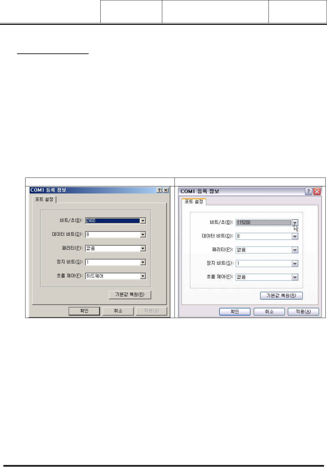
2.1 Hyper Terminal setting
BIT/Sec(B) : 115200
DATA BIT(D) : 8
PARITY(P) : NONE
STOP BIT(S) : 1
FLOW CONTROL : NONE
Primary Value Change Value
2011-03-24 RF Test Manual Ver
1.0
KQF-0705-1(0) LG Electronics Inc. A4(210X297)
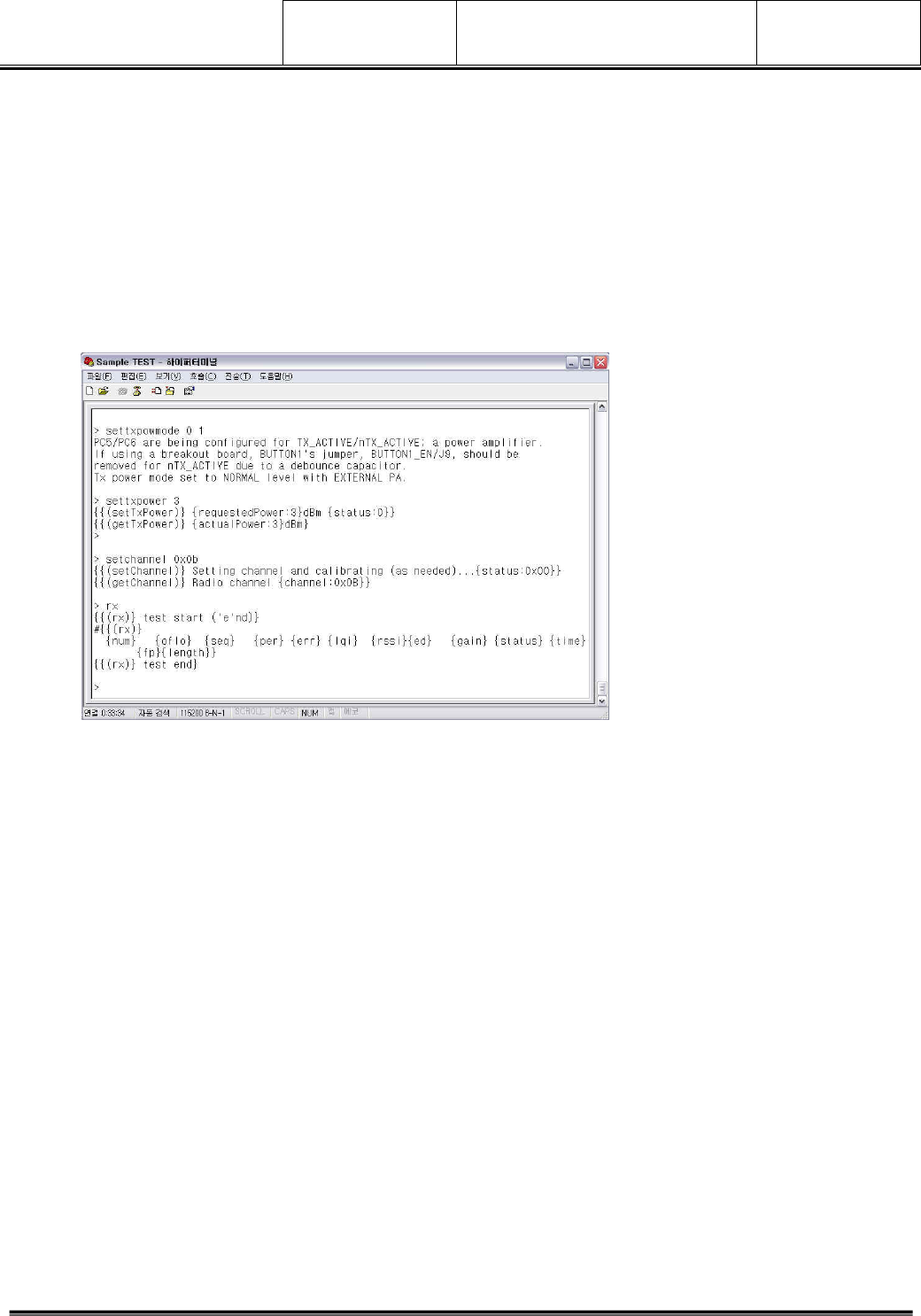
3. TEST COMMAND
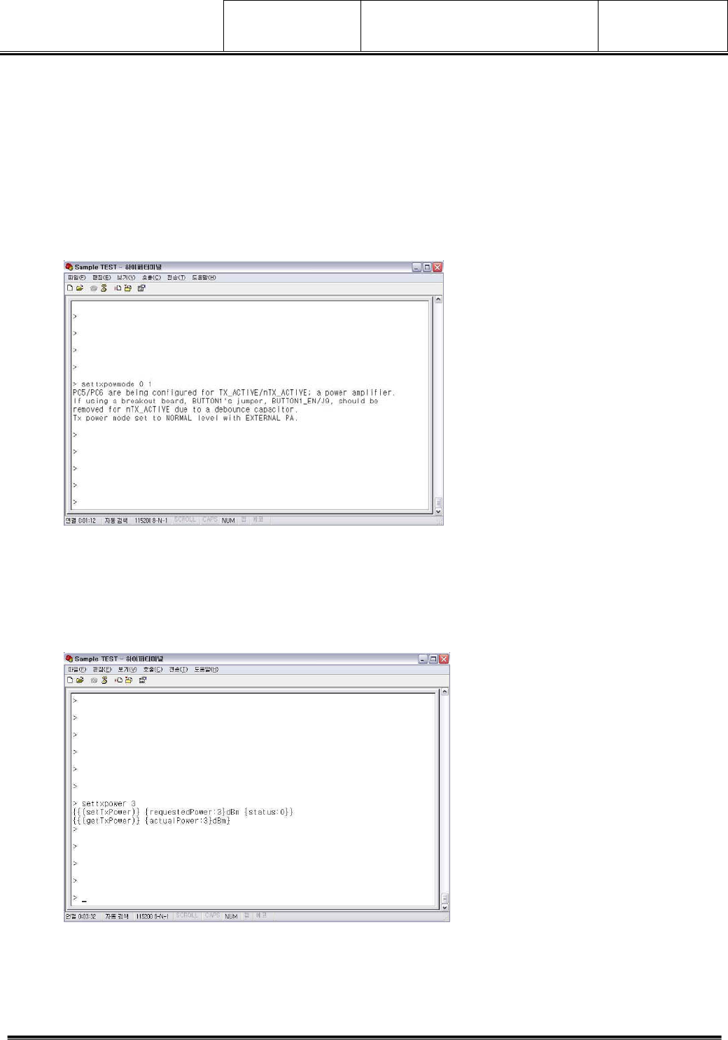
3.1 settxpowmode l p – POWER Mode Setting Command
1) Operation Method
> Command Setting Mode
2) Setting Mode
I p 0 0: Normal-mode, PA-internal
0 1: Normal-mode, PA-External
1 0: Boost-mode, PA-internal
1 1: Boost-mode, PA-External
3) Execution Scene
3.2 settxpower p – Output Power Setting Command
1) Operation Method
> Command Setting Mode
2) Power Range : +8 ~ -32
3) Execution Scene
2011-03-24 RF Test Manual Ver
1.0
KQF-0705-1(0) LG Electronics Inc. A4(210X297)
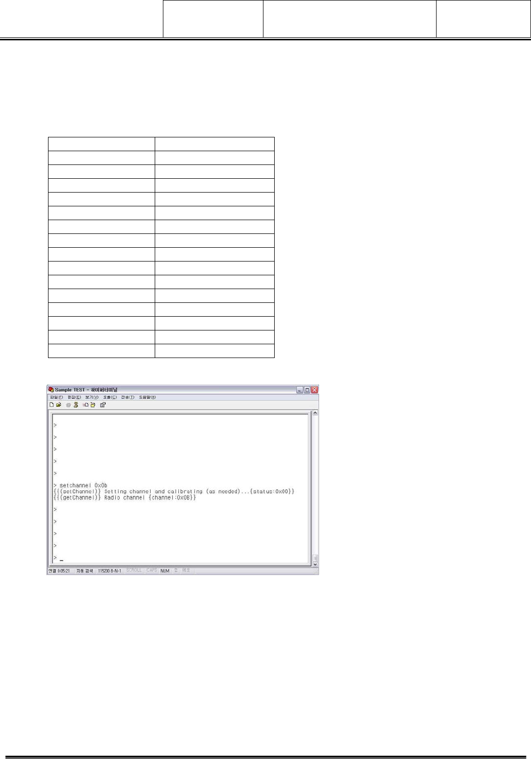
3.3 setchannel c – Channel setting Command
1) Operation Method
> Command Setting Mode (Range: 0x0B ~ 0x1A )
> Channel 0x0B -> Change the 0x0B channel, Channel value must be hexadecimal.
2) Channel Table
Channel 0x0B 2405 MHz
Channel 0x0C 2410 MHz
Channel 0x0D 2415 MHz
Channel 0x0E 2420 MHz
Channel 0x0F 2425 MHz
Channel 0x10 2430 MHz
Channel 0x11 2435 MHz
Channel 0x12 2440 MHz
Channel 0x13 2445 MHz
Channel 0x14 2450 MHz
Channel 0x15 2455 MHz
Channel 0x16 2460 MHz
Channel 0x17 2465 MHz
Channel 0x18 2470 MHz
Channel 0x19 2475 MHz
Channel 0x1A 2480 MHz
3) Execution Scene
2011-03-24 RF Test Manual Ver
1.0
KQF-0705-1(0) LG Electronics Inc. A4(210X297)
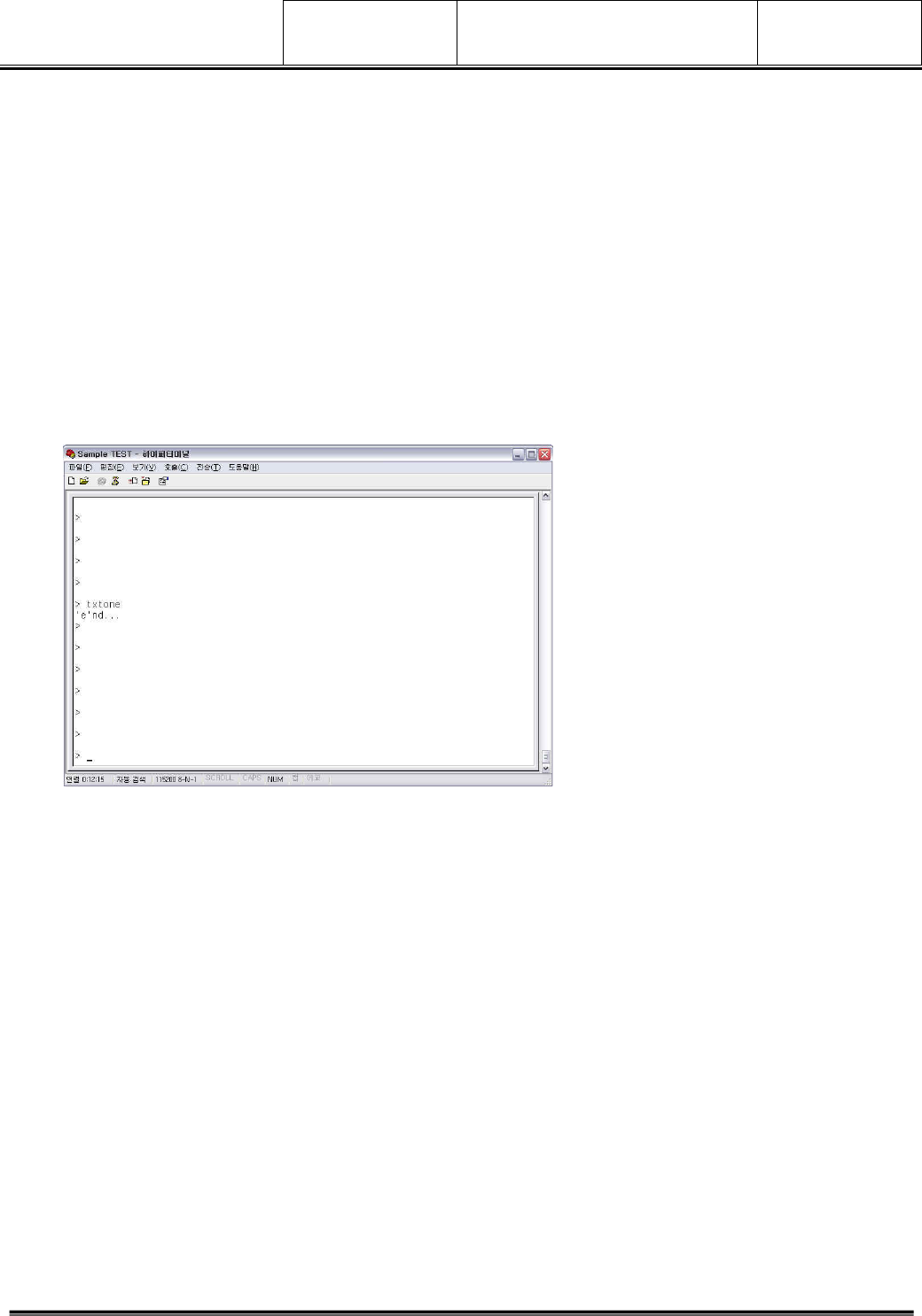
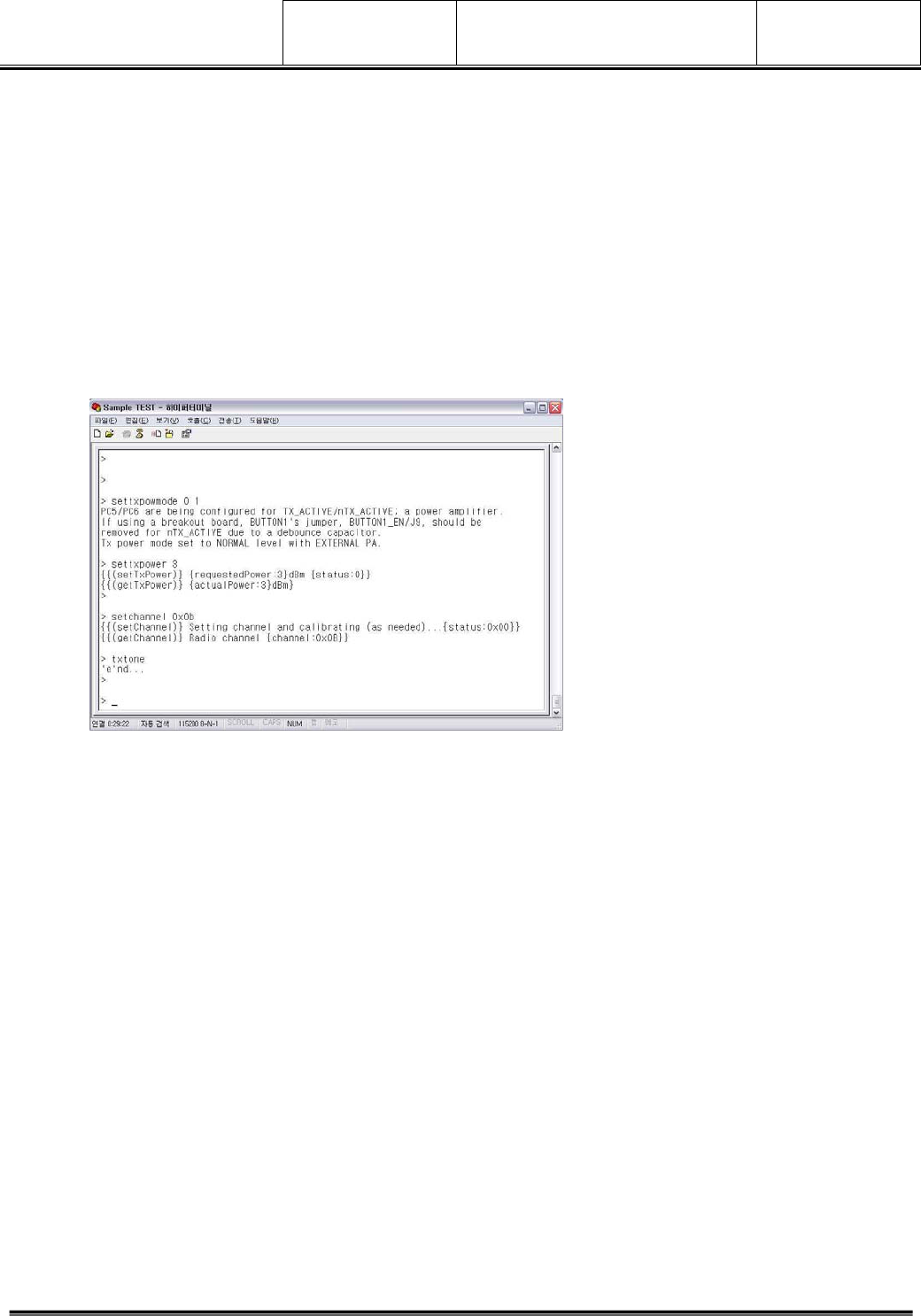
3.3 txtone – Un-modulated Singnal Command
1) Operation Method
> Command Setting Mode
> txtone
Transmitting Carrier frequency. Press 'e'xit to stop
2) txtone (Unmodulated Singnal) TEST
A. settxpowmode 0 1
B. settxpower 0
C. setchannel 0x0B (see the Channel Table)
D. txtone Command Execution
3) Execution Scene
2011-03-24 RF Test Manual Ver
1.0
KQF-0705-1(0) LG Electronics Inc. A4(210X297)
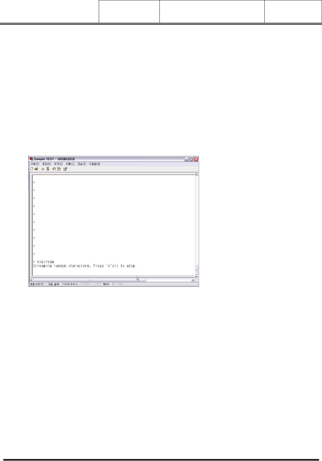
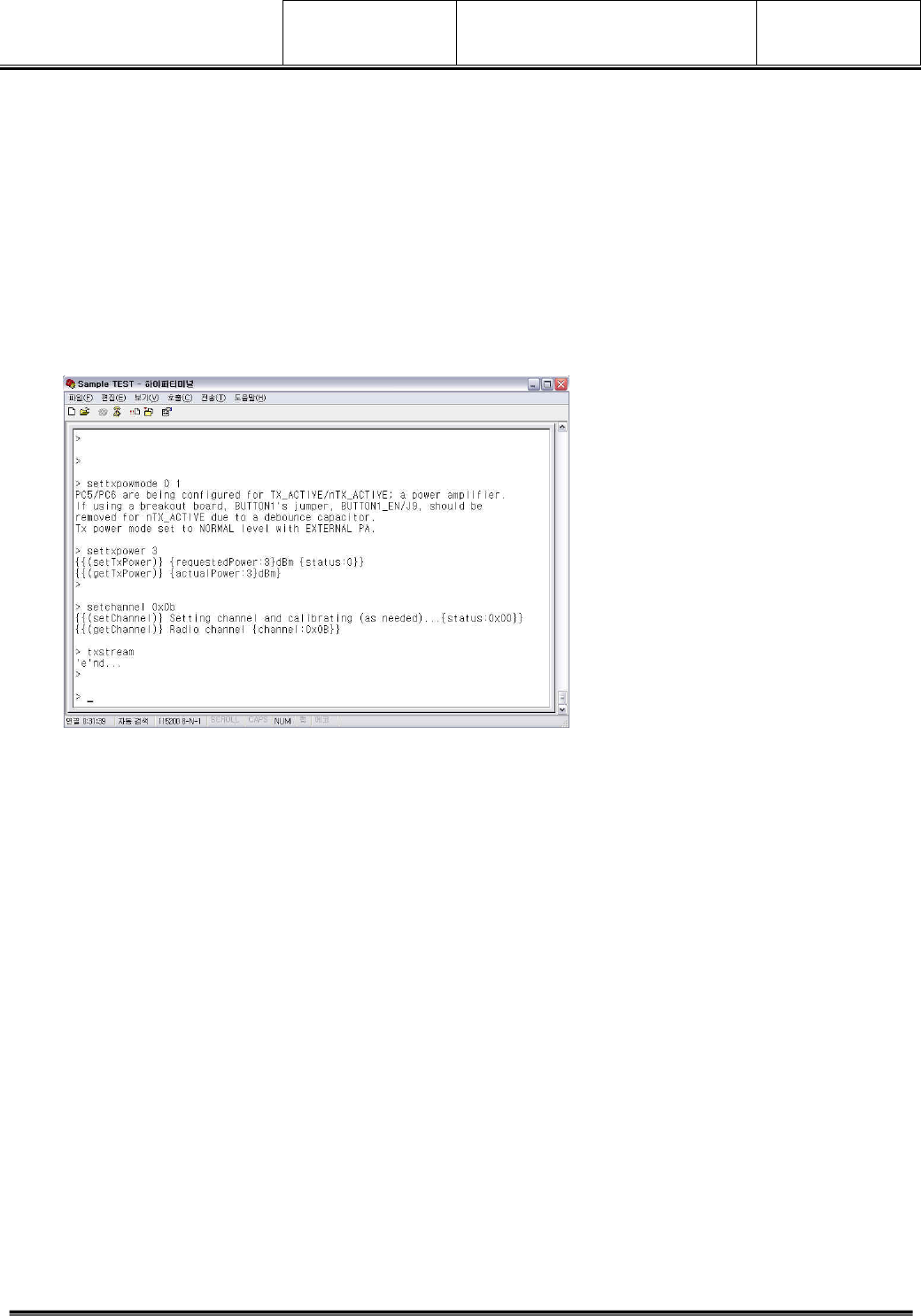
3.4 txstream – Modulated signal’ s Maximum rate transmission mode
1) Operation Method
> Command Setting Mode
> txstream
'e'nd...
2) txstream(Modulated Signal) TEST
A. settxpowmode 0 1
B. settxpower 0
C. setchannel 0x0B (see the Channel Table)
D. txstream Command Execution
3) Execution Scene
2011-03-24 RF Test Manual Ver
1.0
KQF-0705-1(0) LG Electronics Inc. A4(210X297)
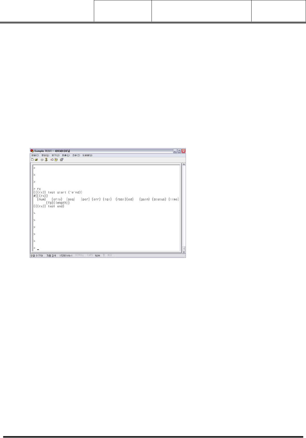
3.5 rx – rx mode
1) Operation Method
> Command Setting Mode
> rx
Entering RX mode, press c to reset, press e to exit
2) rx TEST
A. settxpowmode 0 1
B. settxpower 0
C. setchannel 0x0B (see the Channel Table)
D. rx Command Execution
3) Execution Scene
2011-03-24 RF Test Manual Ver
1.0
KQF-0705-1(0) LG Electronics Inc. A4(210X297)
4. RF TEST Method
4.1 un-modulated CW Signal Test
1) Command input for un-modulated signal test(txtone)
A. settxpowmode 0 1
B. settxpower 0
C. setchannel 0x0B (see the Channel Table)
D. txtone Command Execution
2) Execution Scene
2011-03-24 RF Test Manual Ver
1.0
KQF-0705-1(0) LG Electronics Inc. A4(210X297)
4.2 Modulated Signal Test
1) Command input for TEST (txstream)
A. settxpowmode 0 1
B. settxpower 0
C. setchannel 0x0B (see the Channel Table)
D. txstream Command Execution
2) Execution Scene
2011-03-24 RF Test Manual Ver
1.0
KQF-0705-1(0) LG Electronics Inc. A4(210X297)
4.3 rx Mode Setting
1) Command input for receive TEST
A. settxpowmode 0 1
B. settxpower 0
C. setchannel 0x0B (see the Channel Table)
D. rx Command execution
2) Execution Scene
This equipment has been tested and found to comply with the limits for a Class A
digital device, pursuant to part 15 of the FCC Rules. These limits are designed to
provide reasonable protection against harmful interference in a residential
installation. This equipment generates, uses and can radiate radio frequency
energy and, if not installed and used in accordance with the instructions, may
cause harmful interference to radio communications. However, there is no
guarantee that interference will not occur in a particular installation. If this
equipment does cause harmful interference to radio or television reception, which
can be determined by turning the equipment off and on, the user is encouraged to
try to correct the interference by one or more of the following measures:
• Reorient or relocate the receiving antenna.
• Increase the separation between the equipment and receiver
• Connect the equipment into an outlet on a circuit different from that to which the
receiver is connected.
• Consult the dealer or an experienced radio/TV technician for help.
Caution: Any changes or modifications to this device not explicitly approved by
manufacturer could void your authority to operate this equipment.
This device complies with part 15 of the FCC Rules. Operation is subject to the following
two conditions: (1) This device may notcause harmful interference, and (2) this
device must accept any interference received, including interference that may
cause undesired operation.
This equipment complies with FCC radiation exposure limits set forth for an uncontrolledenvironment.
This equipment should be installed and operated with minimum 20 cmbetween the radiator and your
body.