LG Innotek TWFMB005D Wi-Fi Module User Manual
LG Innotek Co., Ltd. Wi-Fi Module Users Manual
Users Manual

SPECIFICATIONS
PRODUCT NAME : Dual Band 2T2R MIMO Wi-Fi Module
MODEL NAME : TWFM-B005D
The information contained herein is the exclusive property of LG Innotek
and shall not be distributed, reproduced or disclosed in whole or no in part
without prior written permission of LG Innotek.
(00)-0073
This module will be installed in only TV for Wi-Fi communication.
S P E C I F I C A T I O N
PAGE :
DOCUMENT No :
REG. DATE : 2011.10.22
MODEL NAME : TWFM-B005D
REV. DATE : 2011.10.22
REV.NO : 1.1
HC40787
1/ 16
Change History of Revision
Revision Date Contents of Revision Change Remark
1.0 ’11.10.22 First release Lee
©2011 LGIT. All rights reserved.

S P E C I F I C A T I O N
PAGE :
DOCUMENT No :
REG. DATE : 2011.10.22
MODEL NAME : TWFM-B005D
REV. DATE : 2011.10.22
REV.NO : 1.1
HC40787
2/ 16
Table of Contents
No Description Page
1
Ft
3
1
F
ea
t
ures
3
2 Ordering Information 3
3 Block Diagram 4
4 Absolute Maximum Ratings 4
5 Operating Conditions 5
6
Standard Test Conditions
5
6
Standard
Test
Conditions
5
7 Electrical Specifications 6
8 Environment Tests 11
9 Pin Description 12
10 S/W 13
11
Assembly Drawing
14
11
Assembly
Drawing
14
12 Packing Information 15
©2011 LGIT. All rights reserved.
S P E C I F I C A T I O N
PAGE :
DOCUMENT No :
REG. DATE : 2011.10.22
MODEL NAME : TWFM-B005D
REV. DATE : 2011.10.22
REV.NO : 1.1
HC40787
3/ 16
1. Features
TWFM-B005D is the small size and low power module for IEEE 802.11a/b/g/n wireless
LAN. TWFM-B005D is based on Broadcom BCM43236B solution.
IEEE 802.11 a/b/g/n Dual Band WLAN infrastructure
Size : 90mm x 16mm x 6.45mm
2.4GHz and 5GHz internal PA
Two stream spatial multiplexing up to 300Mbps
PIFA ANT (2T2R MIMO)
Use on-chip OTP (One-Time Programmable)
USB 2.0
Supports drivers for Windows Vista, 2000, XP, Linux
Security : WPA,WPA2,AES(TKIP) ,IEEE 802.1X
• Application: DTV, DVR, HD DVD Player, Blue-ray Disk Player, STB
2. Ordering Information
Model Description
TWFM
B005D
Wi
Fi Mod le D al Band 2T2R MIMO
TWFM
-
B005D
Wi
-
Fi
Mod
u
le
,
D
u
al
Band
2T2R
MIMO
©2011 LGIT. All rights reserved.
S P E C I F I C A T I O N
PAGE :
DOCUMENT No :
REG. DATE : 2011.10.22
MODEL NAME : TWFM-B005D
REV. DATE : 2011.10.22
REV.NO : 1.1
HC40787
4/ 16
RF
802.11n MAC
ANT
S
USB 2 0
ANT
BCM43236B
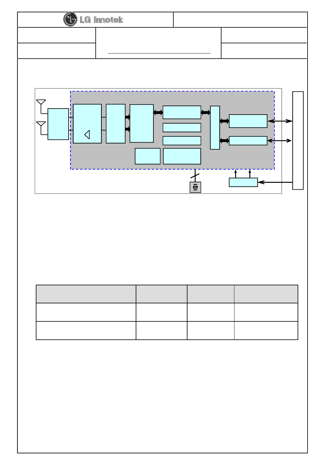
3. Block Diagram
RF
Switch+
diplexer
3.3V 1.2V
2.4GHz PA
5GHz PA
2 x 2
Radio
802.11n
PHY Security
OTP(2K bits)
S
ystem Bus
GPIO
USB
2
.
0
or
HSIC
ANT
USB Connector
ARM Cortex
M3 CPU
384K
Memory
4. Absolute Maximum Ratings
Main Clock(20MHz) DC-DC
5V
< Fig.1 Hardware Block Diagram >
Parameter
Min
Max
Unit
Caution : The specifications in Table 1 define levels at which permanent damage to the
device can occur. Function operation is not guaranteed under these conditions.
Operating at absolute maximum conditions for extend periods can adversely affect the
long-term reliability of the device.
Parameter
Min
Max
Unit
Storage Temperature -10 +80 ℃
Storage Humidity (40℃)-90 %
< Table 1 Absolute Maximum Ratin
g
s >
g
. Other conditions
1) Do not use or store modules in the corrosive atmosphere, especially where chloride
gas, sulfide gas, acid, alkali, salt or the like are contained.
Also, avoid exposure to moisture.
2) Store the modules where the temperature
©2011 LGIT. All rights reserved.
2)
Store
the
modules
where
the
temperature
and relative humidity do not exceed 5 to 40℃and 20 to 60%.
3) Assemble the modules within 6 months.
Check the soldering ability in case of 6 months over.
S P E C I F I C A T I O N
PAGE :
DOCUMENT No :
REG. DATE : 2011.10.22
MODEL NAME : TWFM-B005D
REV. DATE : 2011.10.22
REV.NO : 1.1
HC40787
5/ 16
5. Operating Conditions
Parameter Min Typ Max Unit
Operating Temperature -10 - +60 ℃
Operating Humidity - - 85 %
Supply
Voltage VDD_5V 4.5 5.0 5.5 Vdc
6. Standard Test Conditions
The Test for electrical specification shall be performed under the following condition
unless otherwise specified.
1). Ambient condition
Temperature : 25
℃
±
5
℃
.
Temperature
:
25
℃
±
5
℃
. Humidity : 65% ±5% R.H.
2). Power supply voltages
. 5V (±5%) input power at the Module
3). Current consumption over recommended range of supply voltage and operating
conditions is like below.
When it’s tested, it must be supplied more than 2 times of maximal current.
©2011 LGIT. All rights reserved.
FCC (Federal Communications Commission)
WARNING: This equipment may generate or use radio frequency energy.
Changes or modifications to this equipment may cause harmful interference unless
the modifications are expressly approved in the instruction manual.
The user could lose the authority to operate this equipment if an unauthorized change
or modification is made.
This device complies with Part 15 of the FCC`s Rules. Operation is subject to
the following two Conditions:
1. This device may not cause harmful interference, and
2. This device must accept ant interference received,
including interference that may cause undesirable operation.
To satisfy FCC exterior labeling requirements, the following text must be placed
on the exterior of the end product.
Contains Transmitter module FCC ID: YZP-TWFMB005D
The antenna must be installed such that 20 cm is maintained between the antenna and users,
and the transmitter module may not be co-located with any other transmitter or antenna.
End users cannot modify this transmitter device. Any Unauthorized modification could void
the user`s authority to operate this device.
S P E C I F I C A T I O N
PAGE :
DOCUMENT No :
REG. DATE : 2011.10.22
MODEL NAME : TWFM-B005D
REV. DATE : 2011.10.22
REV.NO : 1.1
HC40787
6/ 16
7. Electrical Specifications
Current Consumption Min. Typ. Max. Unit
TX M d ( MCS7)
470
1) DC Characteristics
2) RF Characteristics for IEEE802.11b ( 11Mbps mode unless otherwise specified)
TX
M
o
d
e
(
MCS7)
-
470
-
mAIdle and Associated state - 215 -
Radio disabled state - 100 -
Items Contents
Specification IEEE802.11b
Mode DSSS/CCK
Channel frequency 2400 ~ 2483 MHz
Data rate 1,2,5.5,11Mbps
TX Characteristics Min. Typ. Max. Unit
Power Level 13 15 17 dBm
Spectrum Mask
1st side lobes ( to fc ±11MHz) --43-30dBr
2nd side lobes ( to fc ±22MHz) --58-50dBr
Modulation Accuracy (EVM) - 30 35 %
Power On/Off ramp
-
0.5
2.0
usec
Power
On/Off
ramp
0.5
2.0
usec
Freq. Tolerance -25 - 25 ppm
Chip Clock Freq. Tolerance -25 - 25 ppm
RX Characteristics Min. Typ. Max. Unit
Minimum Input Level Sens (FER ≤8%)
88
76
dBm
©2011 LGIT. All rights reserved.
Minimum
Input
Level
Sens
.
(FER
≤
8%)
-
88
-
76
dBm
Maximum Input Level (FER ≤ 8%) -10 - - dBm
* Normal Condition : 25℃, VDD=5V.
S P E C I F I C A T I O N
PAGE :
DOCUMENT No :
REG. DATE : 2011.10.22
MODEL NAME : TWFM-B005D
REV. DATE : 2011.10.22
REV.NO : 1.1
HC40787
7/ 16
Items Contents
S ifi ti IEEE502 11
3) RF Characteristics for IEEE802.11g ( 54Mbps mode unless otherwise specified)
Specification IEEE502.11g
Mode OFDM
Channel frequency 2400 ~ 2483.5 MHz
Data rate 6,9,12,18,24,36,48,54Mbps
,,,,,,, p
TX Characteristics Min. Typ. Max. Unit
Power Level 13 15 17 dBm
Spectrum Mask
at fc ±11MHz --32-20dBr
at fc ±20MHz --43-28dBr
at fc ≥ ±30MHz --48-40dBr
Constellation Error (EVM) - -34 -25 dB
Freq. Tolerance -20 - 20 ppm
Chip Clock Freq. Tolerance -20 - 20 ppm
RX Characteristics Min. Typ. Max. Unit
Minimum Input Level Sens. (PER ≤ 10%) - -75 -65 dBm
Maximum Input Level (PER ≤ 10%) -20 - - dBm
*
Normal Condition : 25
℃
VDD=5V
©2011 LGIT. All rights reserved.
Normal
Condition
:
25
℃
,
VDD=5V
.
S P E C I F I C A T I O N
PAGE :
DOCUMENT No :
REG. DATE : 2011.10.22
MODEL NAME : TWFM-B005D
REV. DATE : 2011.10.22
REV.NO : 1.1
HC40787
8/ 16
Items Contents
S ifi ti IEEE802 11
4) RF Characteristics for IEEE802.11a ( 54Mbps mode unless otherwise specified)
Specification IEEE802.11a
Mode OFDM
Channel frequency 5150~5250MHz, 5725 ~ 5850MHz
Data rate
6,9,12,18,24,36,48,54Mbps
Data
rate
6,9,12,18,24,36,48,54Mbps
TX Characteristics Min. Typ. Max. Unit
Power Level 11 13 15 dBm
Spectrum Mask
at fc ±11MHz --32-20dBr
at fc ±20MHz --43-28dBr
at fc ≥ ±30MHz --48-40dBr
Constellation Error (EVM) - -34 -25 dB
Freq. Tolerance -20 - 20 ppm
Chip Clock Freq. Tolerance -20 - 20 ppm
RX Characteristics Min. Typ. Max. Unit
Minimum Input Level Sens. (PER ≤ 10%) - -72 -65 dBm
Maximum Input Level (PER ≤ 10%) -30 - - dBm
©2011 LGIT. All rights reserved.
* Normal Condition : 25℃, VDD=5V.
S P E C I F I C A T I O N
PAGE :
DOCUMENT No :
REG. DATE : 2011.10.22
MODEL NAME : TWFM-B005D
REV. DATE : 2011.10.22
REV.NO : 1.1
HC40787
9/ 16
Items Contents
S ifi ti IEEE802 11 5GH
5) RF Characteristics for IEEE802.11an ( MCS7 mode unless otherwise specified)
Specification IEEE802.11n –5GHz
Mode OFDM
Channel frequency 5150~5250MHz, 5725 ~ 5850MHz
Data rate
Data
rate
~135Mbps
TX Characteristics Min. Typ. Max. Unit
Power Level (HT20 / HT40 : MCS7) 11 13 15 dBm
Spectrum Mask (HT20)
at fc ±11MHz --32-20dBr
at fc ±20MHz --35-28dBr
at fc ±30MHz --45-40dBr
Constellation Error (EVM) - -32 -28 dB
Freq. Tolerance -20 - 20 ppm
Chip Clock Freq. Tolerance -20 - 20 ppm
RX Characteristics Min. Typ. Max. Unit
Minimum Input Level Sens.
(HT20,PER ≤ 10%) --71-64dBm
Minimum Input Level Sens.
(
HT40,PER ≤ 10%
)
--68-61dBm
©2011 LGIT. All rights reserved.
( )
Maximum Input Level (PER ≤ 10%) -30 - - dBm
* Normal Condition : 25℃, VDD=5V.

S P E C I F I C A T I O N
PAGE :
DOCUMENT No :
REG. DATE : 2011.10.22
MODEL NAME : TWFM-B005D
REV. DATE : 2011.10.22
REV.NO : 1.1
HC40787
10 / 16
Items Contents
Sifii IEEE802 11 24GH
6) RF Characteristics for IEEE802.11gn ( MCS7 mode unless otherwise specified)
Specification IEEE802.11n – 2.4GHz
Mode OFDM
Channel frequency 2400 ~ 2483.5 MHz
Data rate
6 5 13 19 5 26 39 52 58 5 65Mbps
Data
rate
6
.
5
,
13
,
19
.
5
,
26
,
39
,
52
,
58
.
5
,
65Mbps
TX Characteristics Min. Typ. Max. Unit
Power Level (HT20/HT40 : MCS7) 11 13 15 dBm
Spectrum Mask (HT20)
at fc ±11MHz --32-20dBr
at fc ±20MHz --35-28dBr
at fc ±30MHz --45-40dBr
Constellation Error (EVM) - -32 -28 dB
Freq. Tolerance -20 - 20 ppm
Chip Clock Freq. Tolerance -20 - 20 ppm
RX Characteristics Min. Typ. Max. Unit
Minimum Input Level Sens.
(HT20,PER ≤ 10%) --73-64dBm
Minimum Input Level Sens.
(HT40,PER ≤ 10%) --70-62dBm
©2011 LGIT. All rights reserved.
Maximum Input Level (PER ≤ 10%) -20 - - dBm
* Normal Condition : 25℃, VDD=5V.

S P E C I F I C A T I O N
PAGE :
DOCUMENT No :
REG. DATE : 2011.10.22
MODEL NAME : TWFM-B005D
REV. DATE : 2011.10.22
REV.NO : 1.1
HC40787
11 / 16
8. Environment Tests
Item Test Conditions Specifications
Heat Load
Test
Initial values are measured at standard test condition.
Leave samples in 60℃±2℃for 500 ±5 hours, and in
standard test condition for 30 minutes, then take
measurements within 1 hour.
-Su
pp
l
y
volta
g
e : standard ±5%
pp y g
- Supply voltage cycle : 1.5h on, 0.5h off
Initial values are measured at standard test condition.
Leave samples in 40
℃
±
5
℃
90 95% RH for 96
±
5
•TX Power
: ±4dB Max
• Min Input
Level
: ±4dB Max
Humidity
Load Test
Leave
samples
in
40
℃
±
5
℃
,
90
~
95%
RH
for
96
±
5
hours, and in standard test condition for 30 minutes,
then take measurements within 1 hour.
- Supply voltage : standard + 5%
- Supply voltage cycle : 1.5h on, 0.5h off
Cold Test
Initial values are measured at standard test condition.
Leave samples in -10℃±2℃for 96 ±5 hours, and
in standard ambient for 1 hour with standard power
Supply then take measurements within 1 hour.
Temperature
Shock
Take measurements in standard test condition.
Temp. : -10℃~ +80℃
Duration : 30 min
Ramp-up & Ramp-down for 5 min
Cycle : 100cycle
©2011 LGIT. All rights reserved.
Cycle
:
100cycle
.
S P E C I F I C A T I O N
PAGE :
DOCUMENT No :
REG. DATE : 2011.10.22
MODEL NAME : TWFM-B005D
REV. DATE : 2011.10.22
REV.NO : 1.1
HC40787
12 / 16
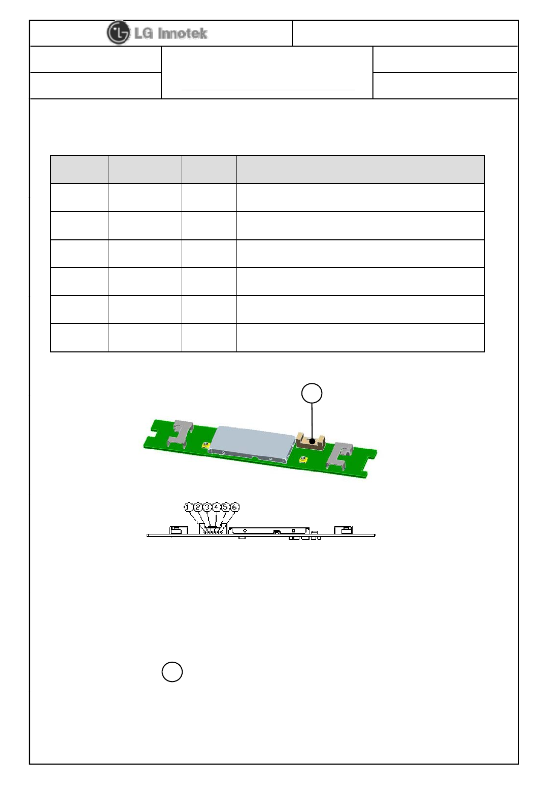
9. Pin Description
Pin No. Pin Name I/O Pin Description
1
VDD
I
VDD 5V
1
VDD
I
VDD
5V
2 USB_DN I/O USB Communication signal USB_DN
3 USB_DP I/O USB Communication signal USB_DP
4 GND - GND
5 WoWLAN O Wake-On - Wireless LAN
6 GND - GND
<TOPVi >
A
<
TOP
Vi
ew
>
A
Note
Note
.
1) Recommend a Module install sequence for prevent USB device failure
- Supply 5V power
- Connect to data signal (USB_DP, USB_DN)
2) If remove the module, proceed in reveres sequence
3) Connector : A1257WR0-6PS ( JWT)
A
©2011 LGIT. All rights reserved.

S P E C I F I C A T I O N
PAGE :
DOCUMENT No :
REG. DATE : 2011.10.22
MODEL NAME : TWFM-B005D
REV. DATE : 2011.10.22
REV.NO : 1.1
HC40787
13 / 16
10. S/W
The module is controlled by wl command. It is intended for those evaluating
and/or testing Broadcom’s IC, describes a subset of the commands available in wl,
the Broadcom ® WLAN client utility.
1) Command Syntax
The syntax is as follows:
wl <adapter> [-h] [-d|u|x] <command> [arguments]
where
-h this message and command descriptions
-d output format signed integer
-u output format unsigned integer
-x output format hexdecimal
The [h,u] option is only to print help.
Other syntax specifics are as follows:
• Entries within square brackets, such as [arguments], are optional. In the above example,
|
switches within brackets, such as
–
h, are typed as shown. The
|
symbol should not be
typed,
it represents the word or.
• Entries within angle brackets, such as <adapter>, are required and indicate that a value
must
be inserted in place of the item contained within the angle brackets.
•
Entries shown outside of either square or angle brackets are to be typed as shown.
Entries
shown
outside
of
either
square
or
angle
brackets
are
to
be
typed
as
shown.
2) Command List and Version
•CMDS
Syntax: wl cmds
Purpose: Generates a list of available commands.
Parameters:None
Returns: All commands available to the attached 43XX chip.
•VER
Syntax: wl ver
Purpose: Generates a list of available commands.
Parameters:None
©2011 LGIT. All rights reserved.
Returns: All commands available to the attached 43XX chip.
•Please refer to ‘80211-TI201-R’ technical document of Broadcom to other
commands.
S P E C I F I C A T I O N
PAGE :
DOCUMENT No :
REG. DATE : 2011.10.22
MODEL NAME : TWFM-B005D
REV. DATE : 2011.10.22
REV.NO : 1.1
HC40787
14 / 16
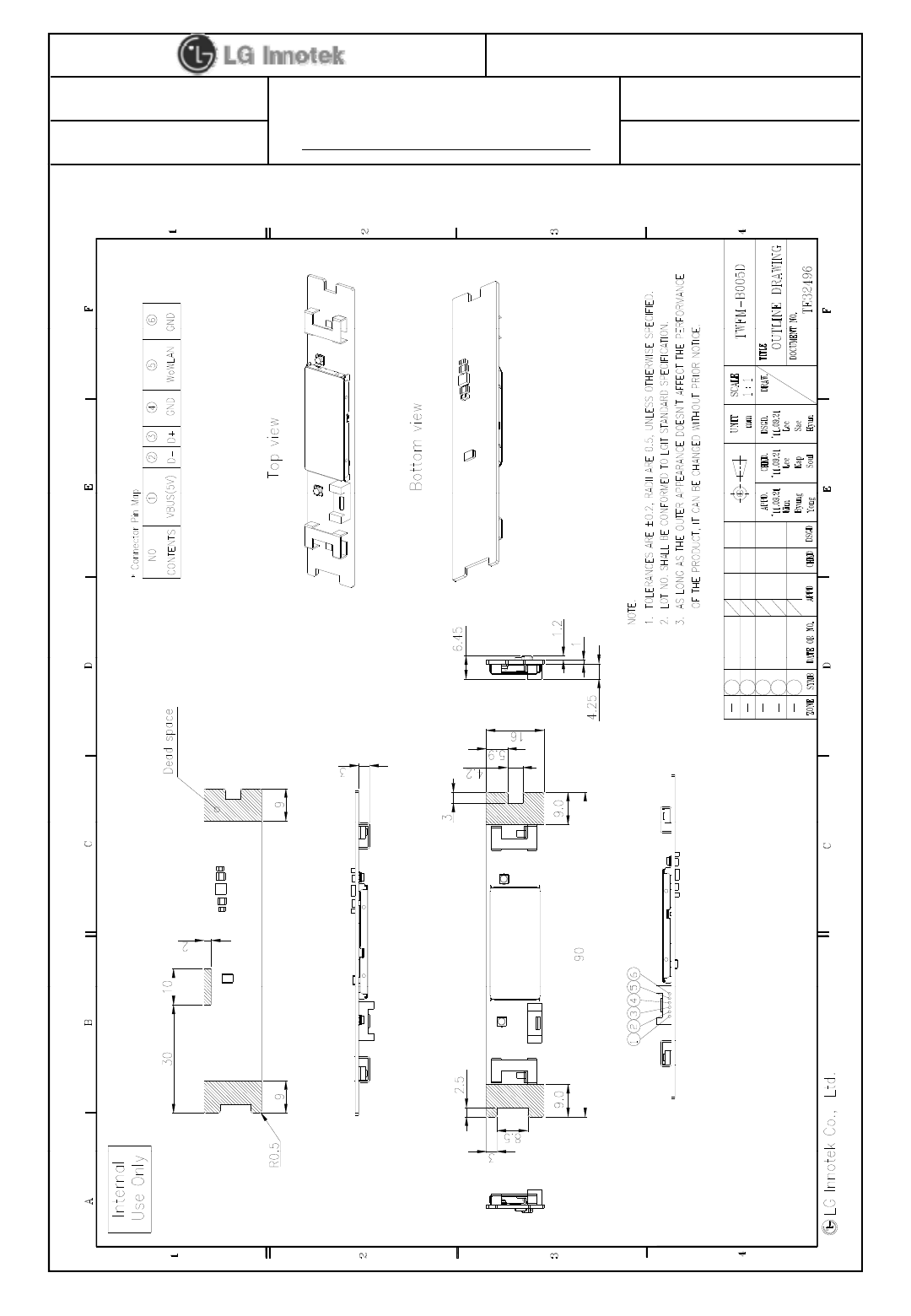
11. Assembly Drawing
©2011 LGIT. All rights reserved.