LG Innotek VL1000 LTE/CDMA(EVDO) Wireless Modem Module User Manual 1
LG Innotek Co., Ltd. LTE/CDMA(EVDO) Wireless Modem Module 1
UserManual.wiki
>
LG Innotek
>
VL1000 User Manual
>
User manual 1 of 2
Contents
1.
Manual
2.
User manual 1 of 2
3.
User manual 2 of 2
User manual 1 of 2
Navigation menu
Upload a User Manual
Namespaces
Wiki Guide
HTML
PDF
Info
Views
User Manual
Discussion / Help
Navigation
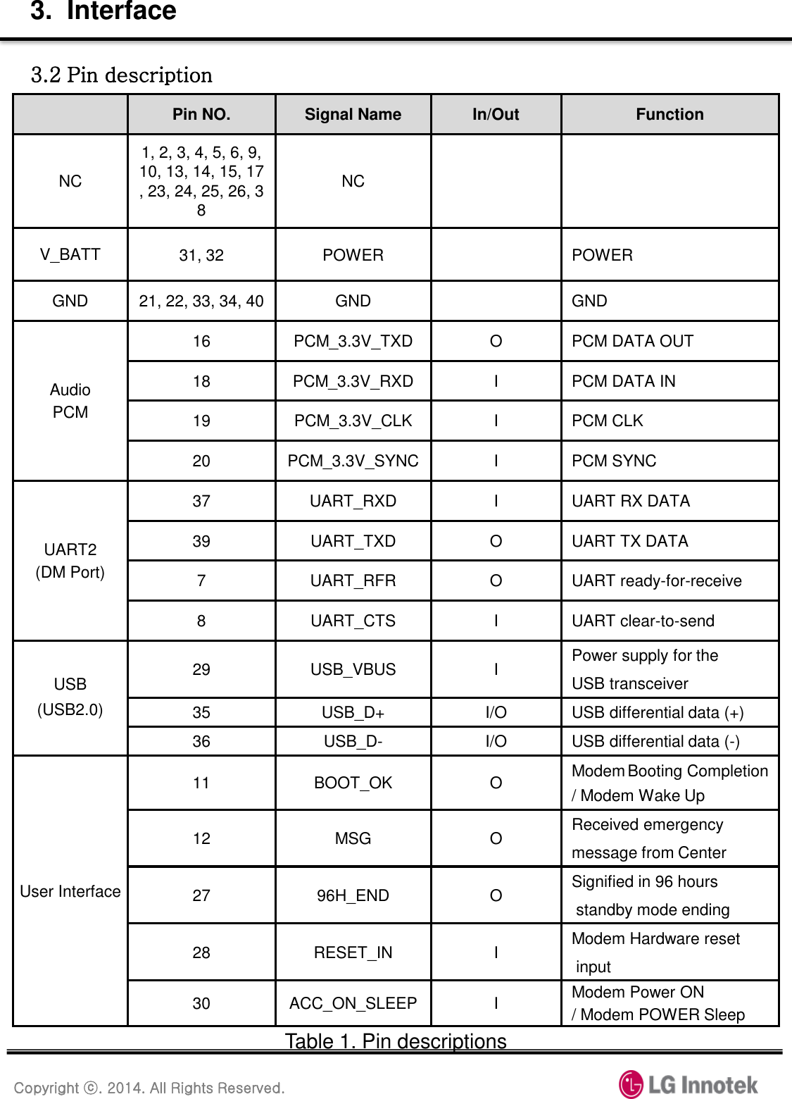
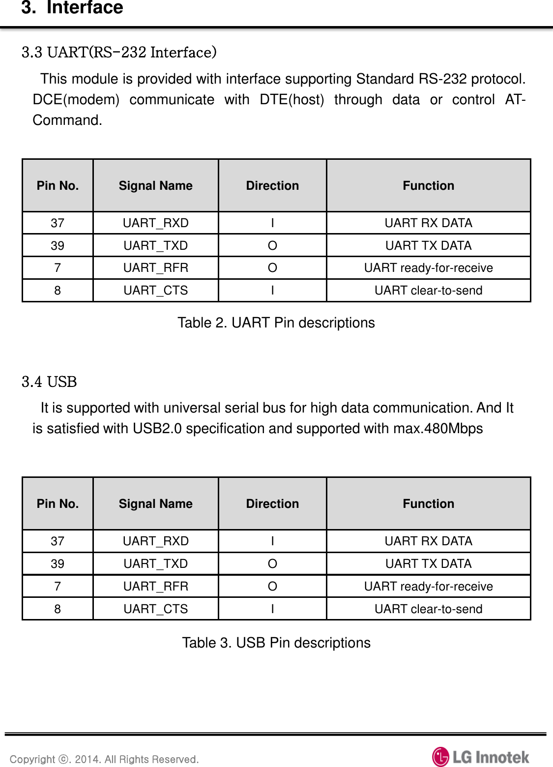
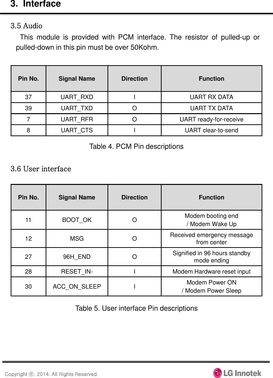
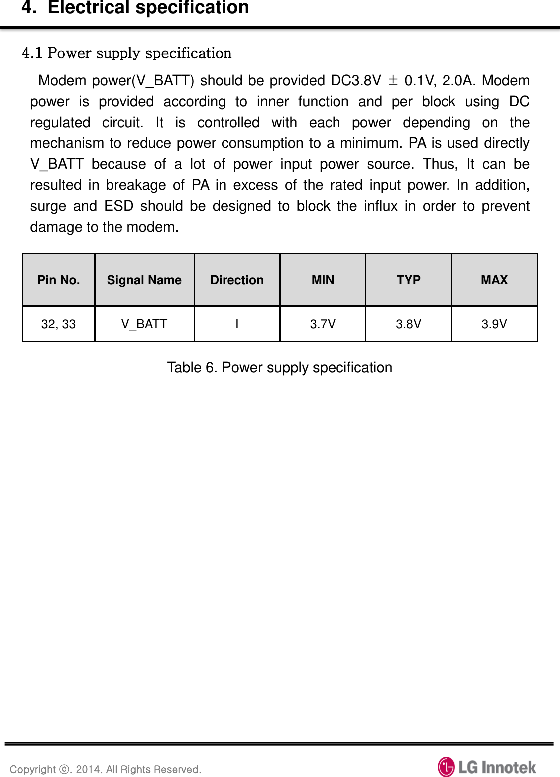

![Copyright ⓒ. 2014. All Rights Reserved. 10. FCC Approval This Module complies with parts 22, 24, 27 of the FCC rules. This device complies with FCC radiation exposure limits set forth for an uncontrolled environment. This module should be installed and operated with minimum distance 20cm between the radiating element of this device and the user. This module may not be co-located with any other transmitters or antennas. To comply with FCC regulations limiting both maximum RF output power and human exposure to RF radiation, the maximum antenna gain including cable loss in a mobile-only exposure condition must not exceed the table below. Band Frequency Range [MHz] Maximum Antenna Gain[dBi] CDMA(Cellular) 824.70~848.31 CDMA(PCS) 1851.25~1908.75 LTE(B13) 779.50~874.50 LTE(B4) 1710.70~1754.30 The satisfy FCC exterior labeling requirements, the following text must be placed on the exterior of the end product. Contains Transmitter module FCC ID: YZP-VL1000 Changes or modifications to this equipment may cause harmful interference unless the modifications are expressly approved in the instruction manual. The user could lose the authority to operate this equipment if an unauthorized change or codification is made. Note: If this module is intended for use in a portable device, additional testing will be required to satisfy RF Exposure, including SAR requirements of FCC Part 2.1093. 5.507.005.314.29](https://usermanual.wiki/LG-Innotek/VL1000.User-manual-1-of-2/User-Guide-2589743-Page-20.png)