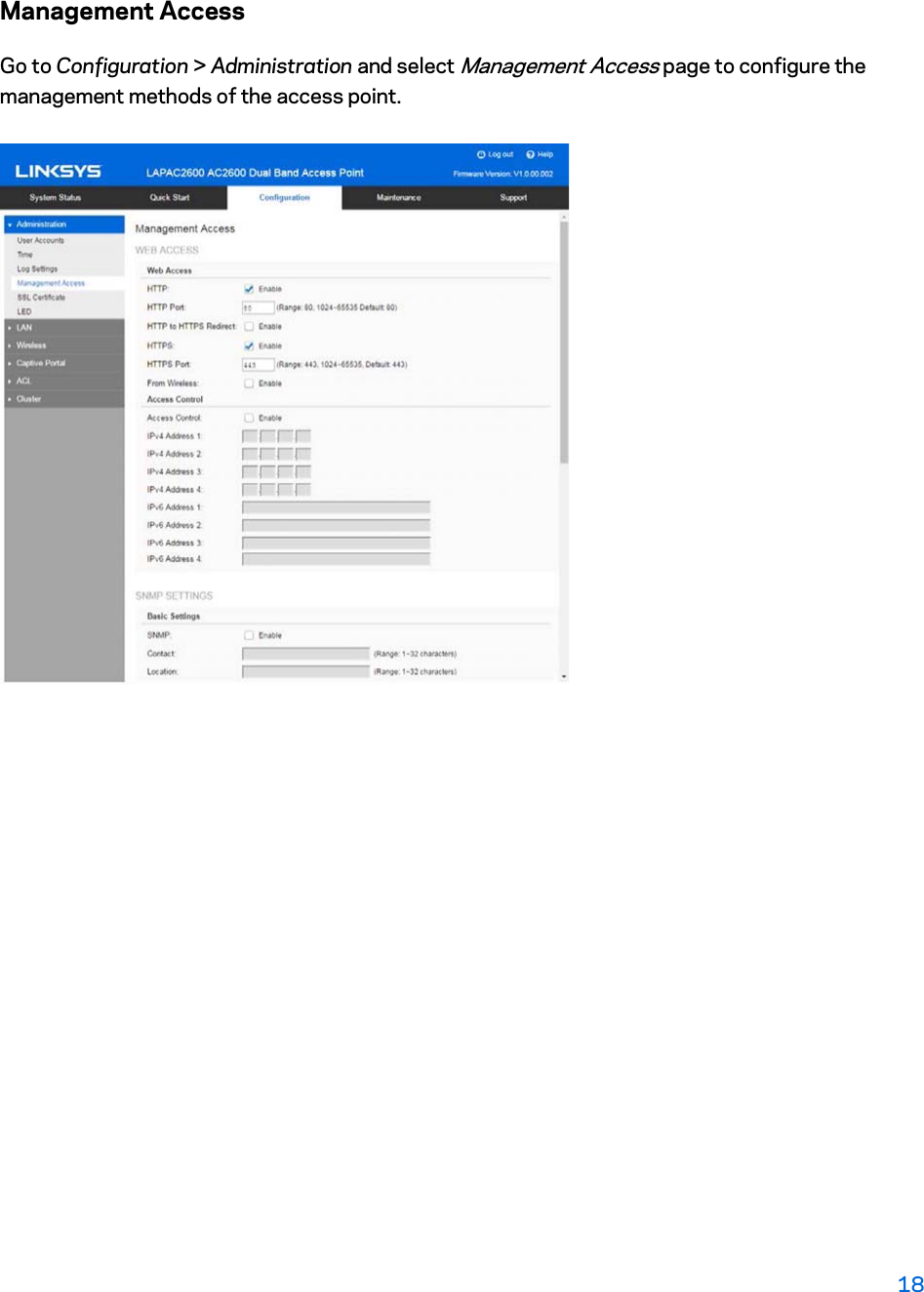
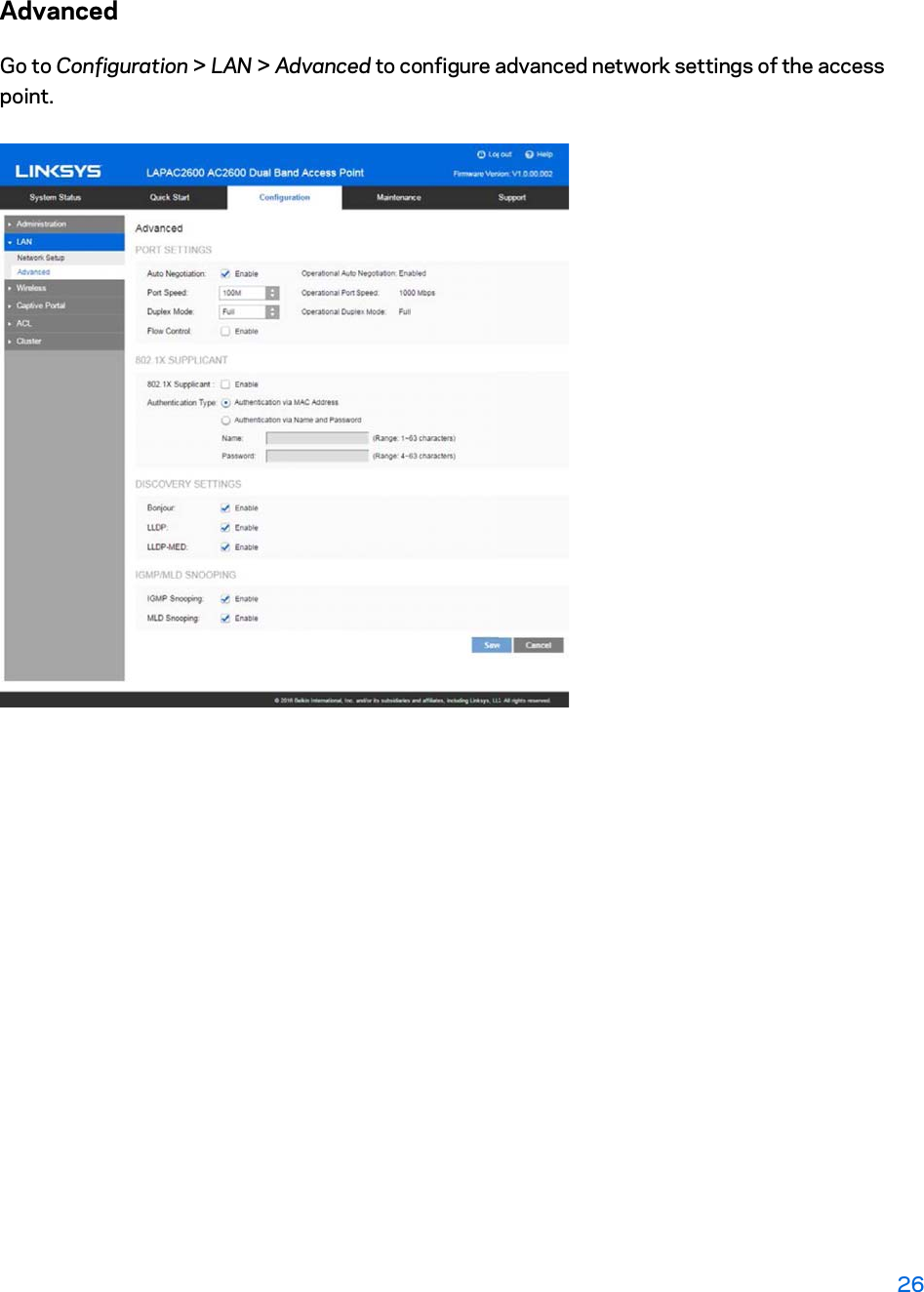
LINKSYS LAPAC2600 LAPAC2600 Dual Band Access Point User Manual
LINKSYS LLC LAPAC2600 Dual Band Access Point
UserManual.wiki
>
LINKSYS
>
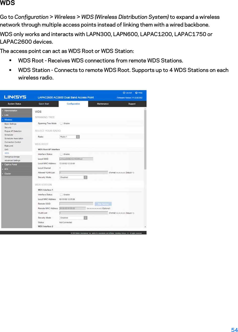
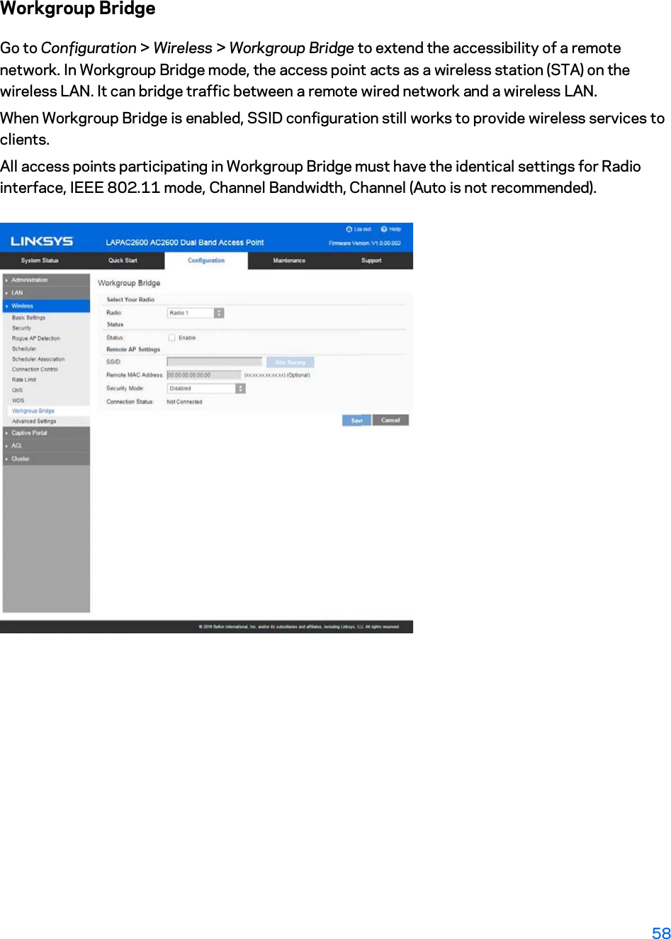
LAPAC2600 User Manual
>
User manual
Contents
1.
User manual statement
2.
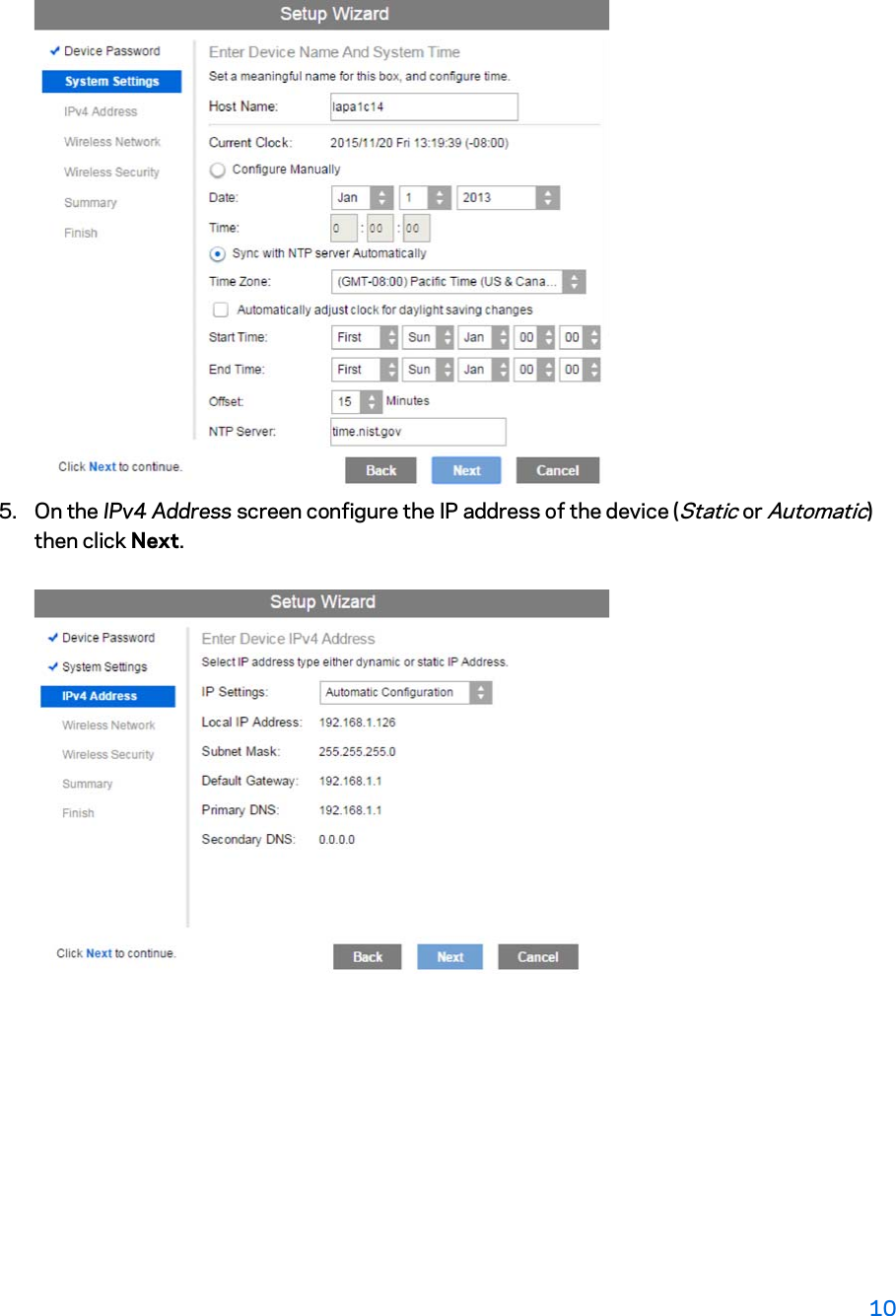
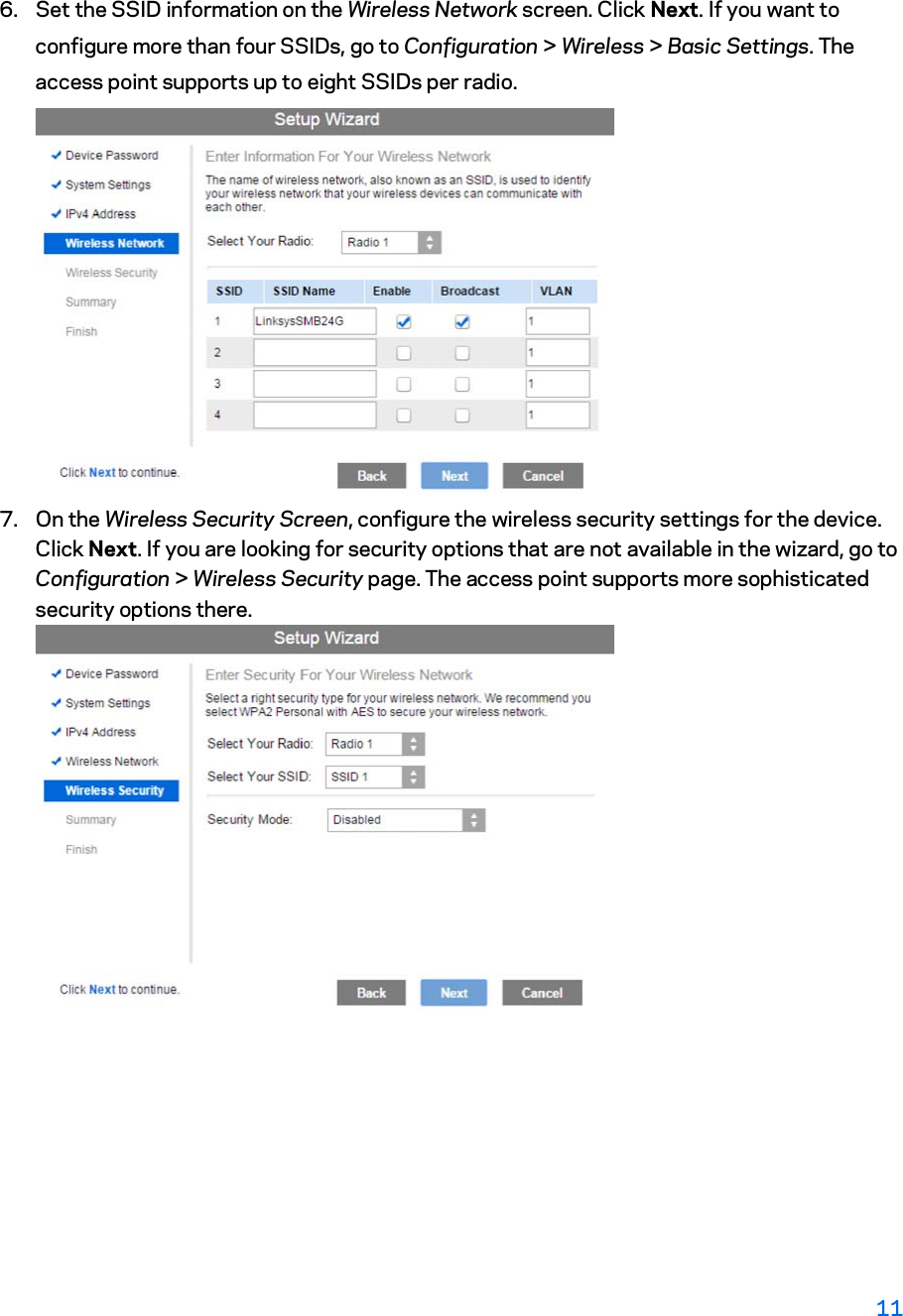
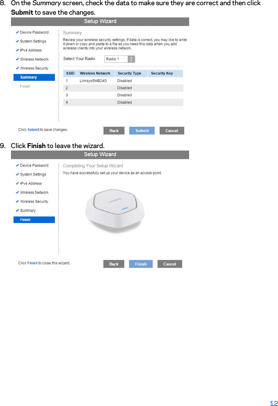
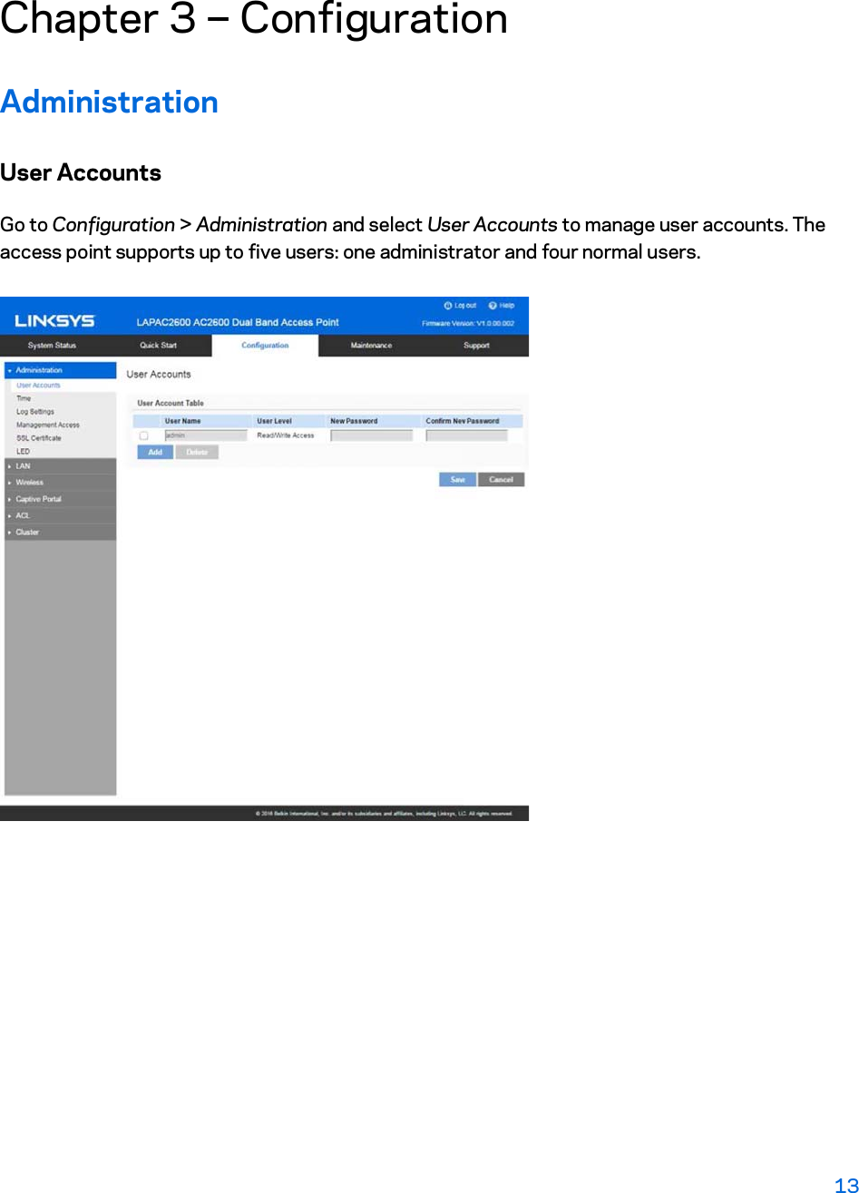
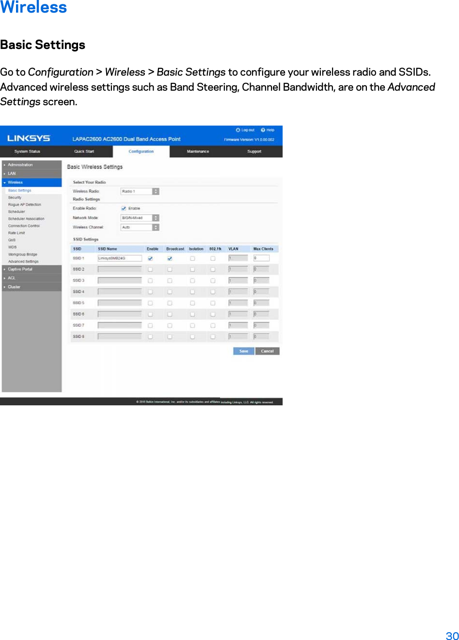
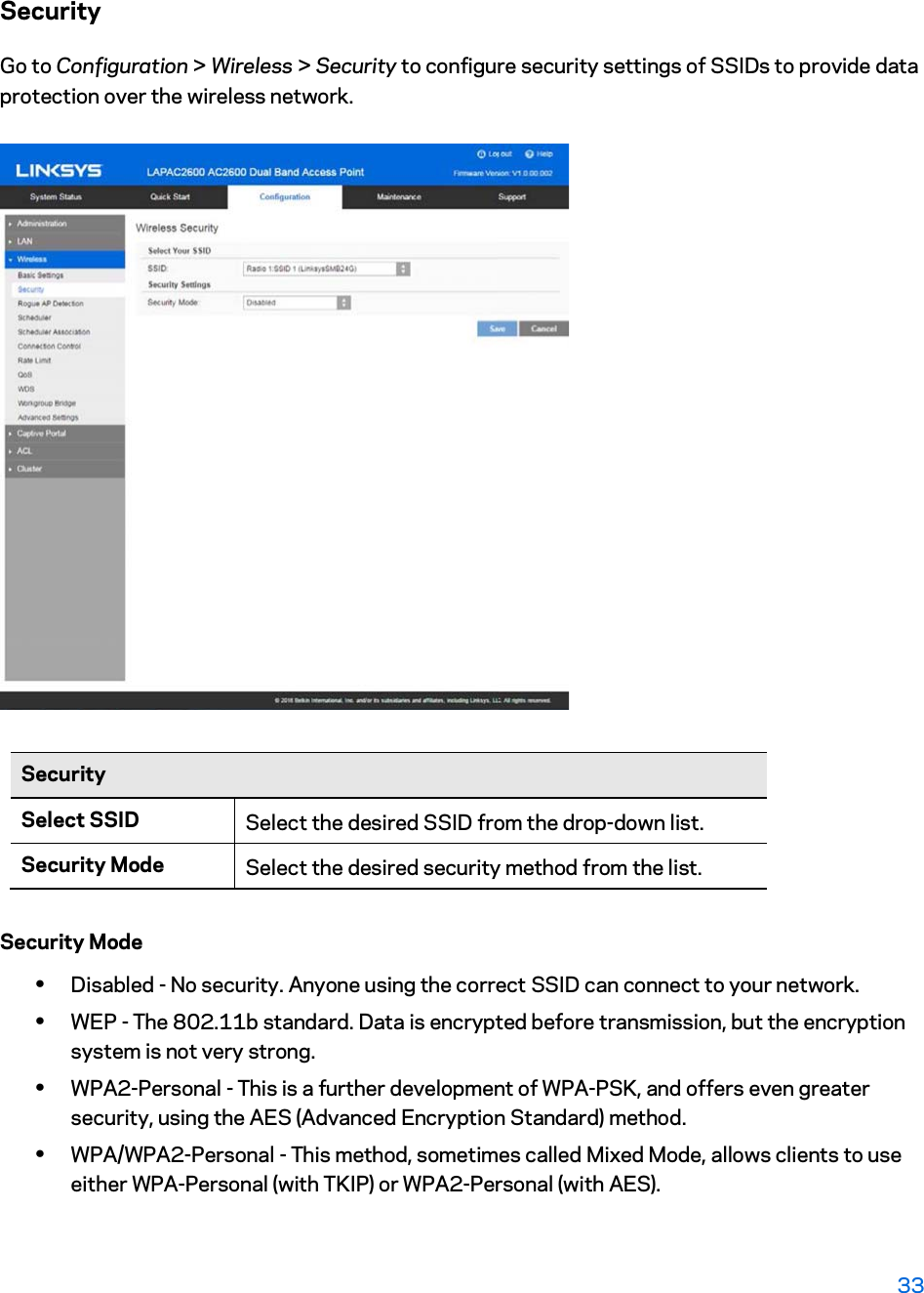
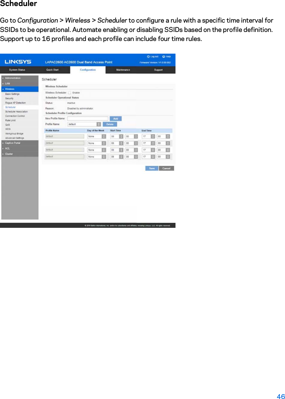
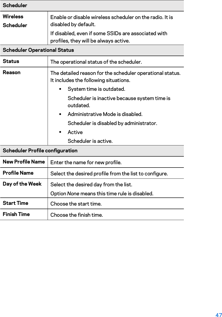
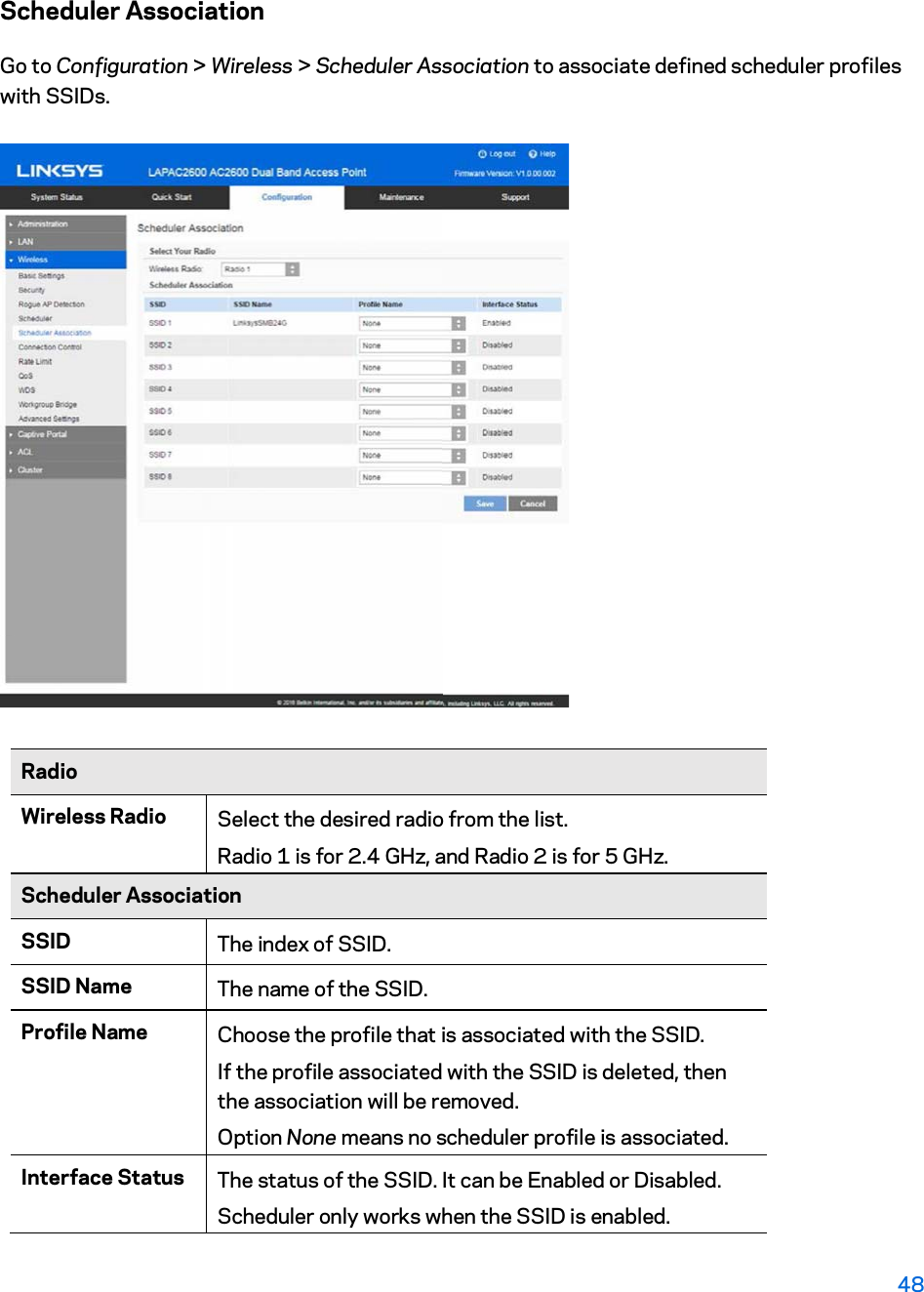
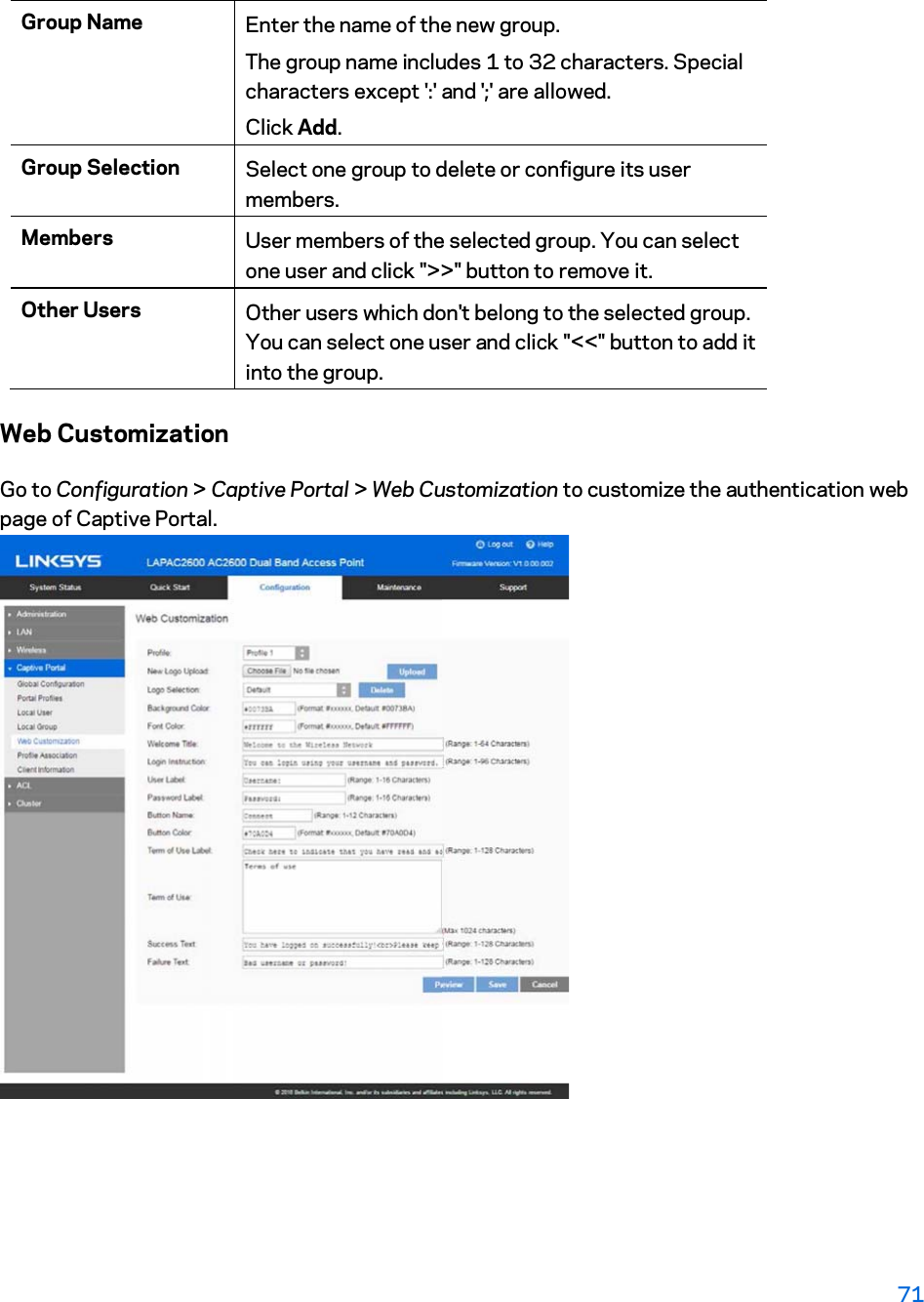
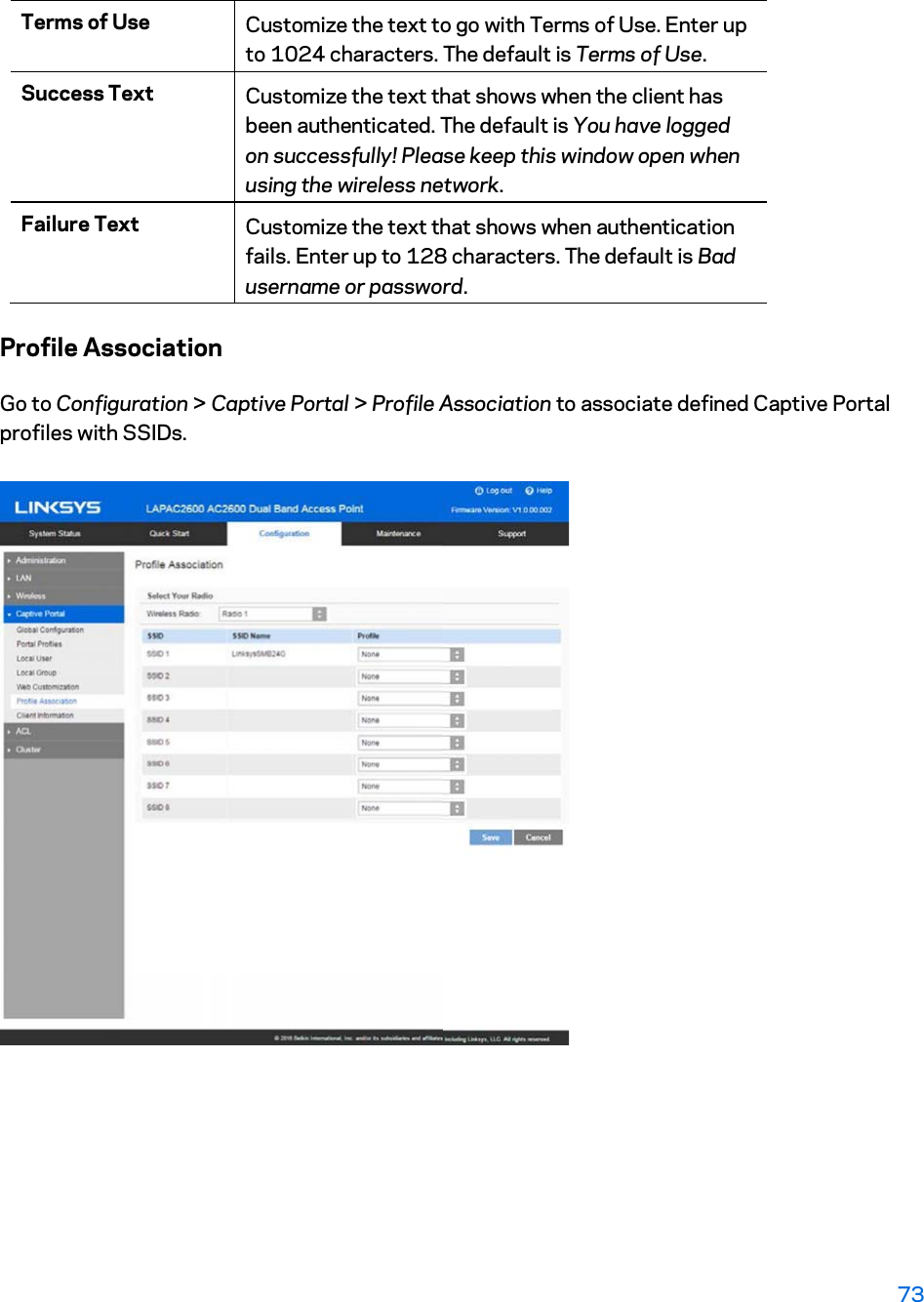
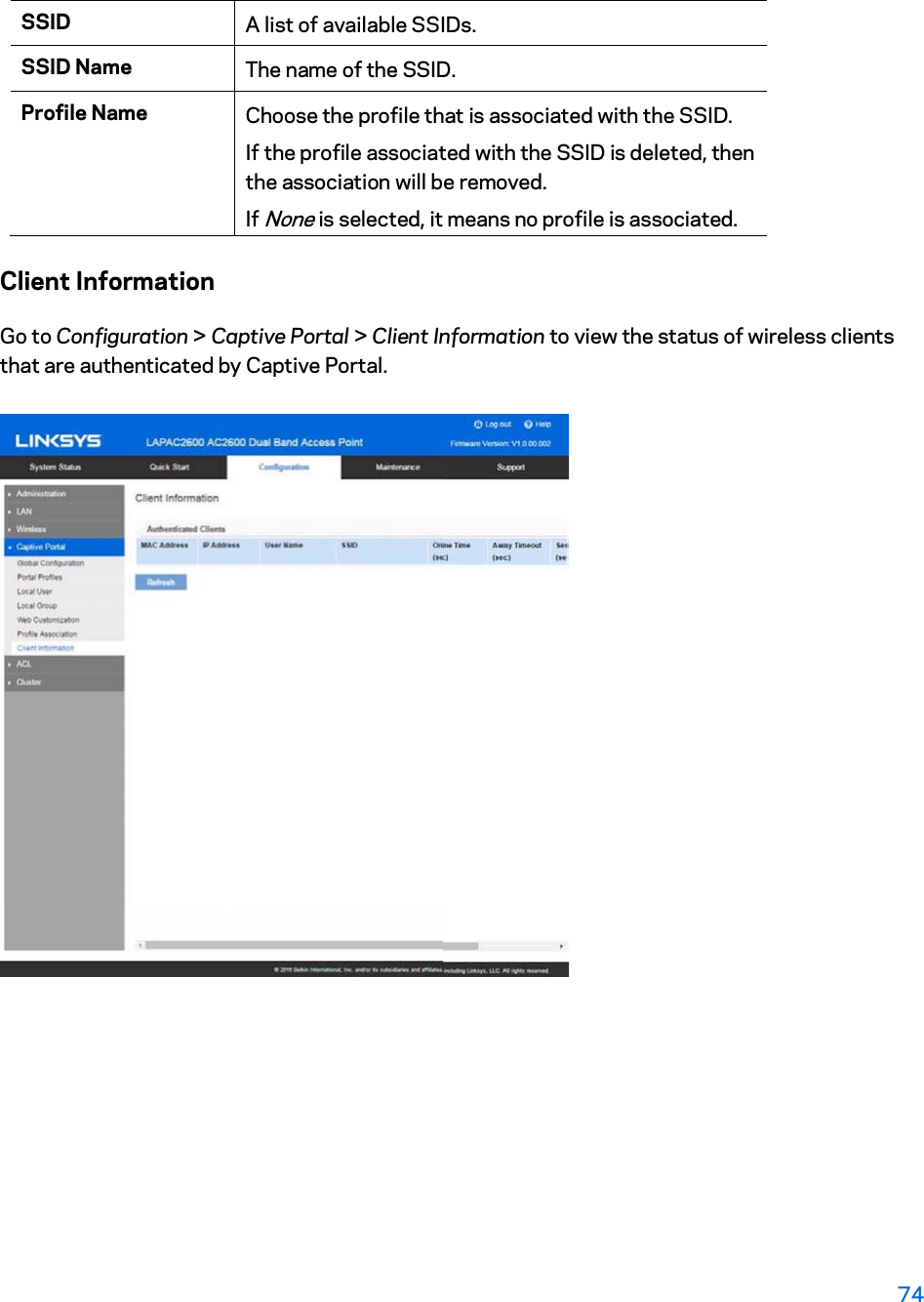
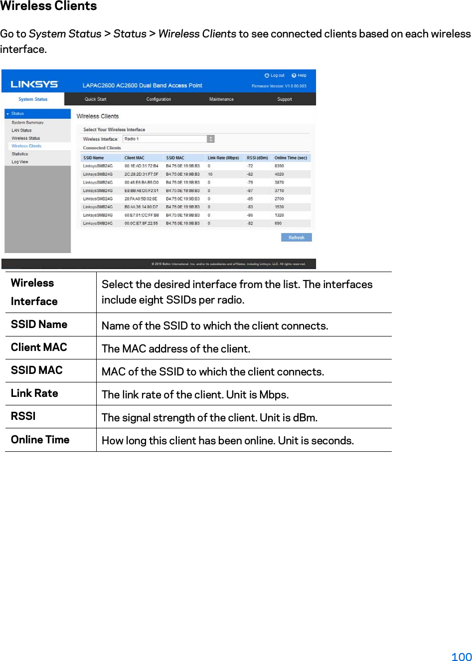
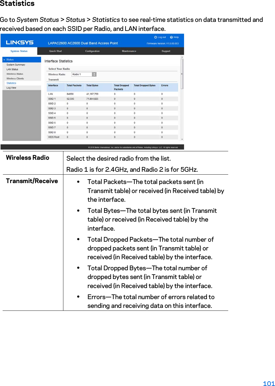
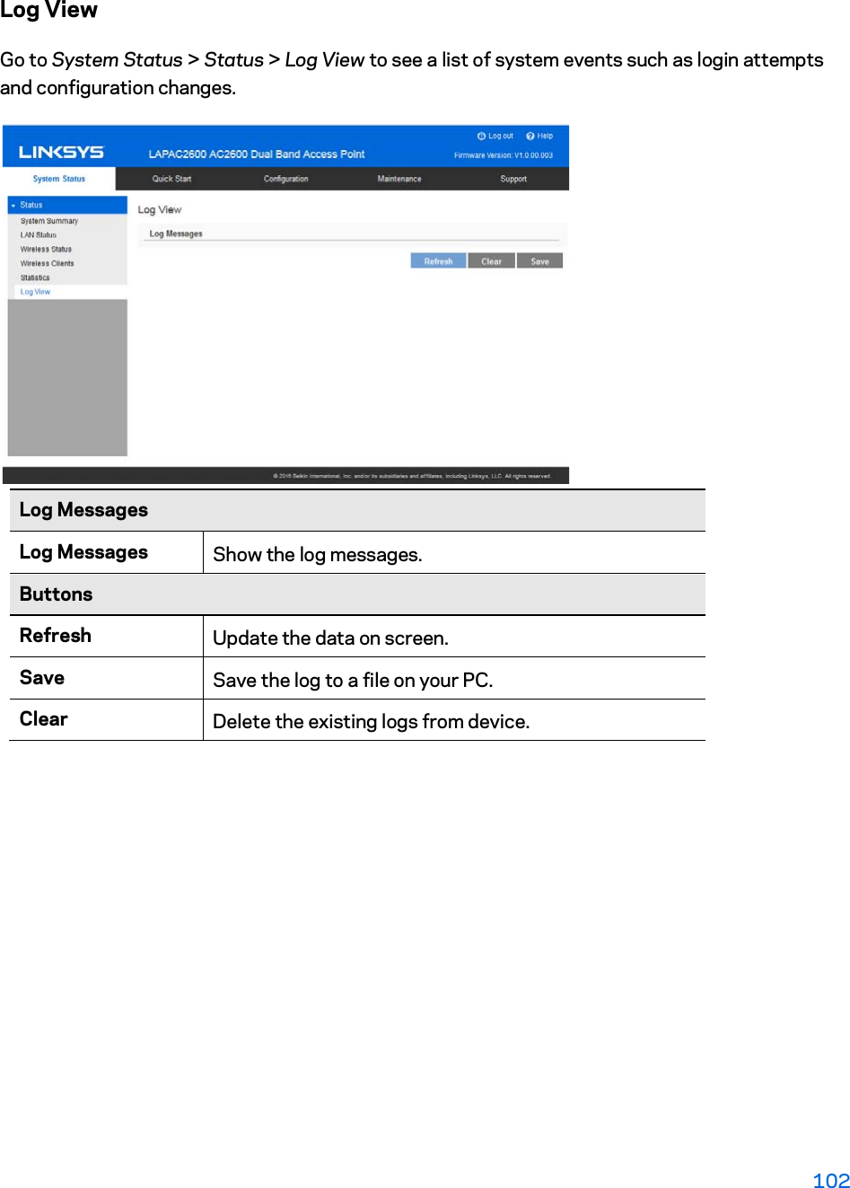
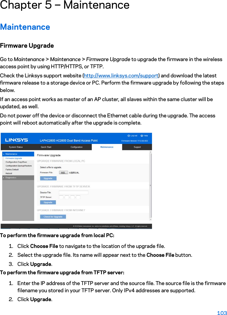
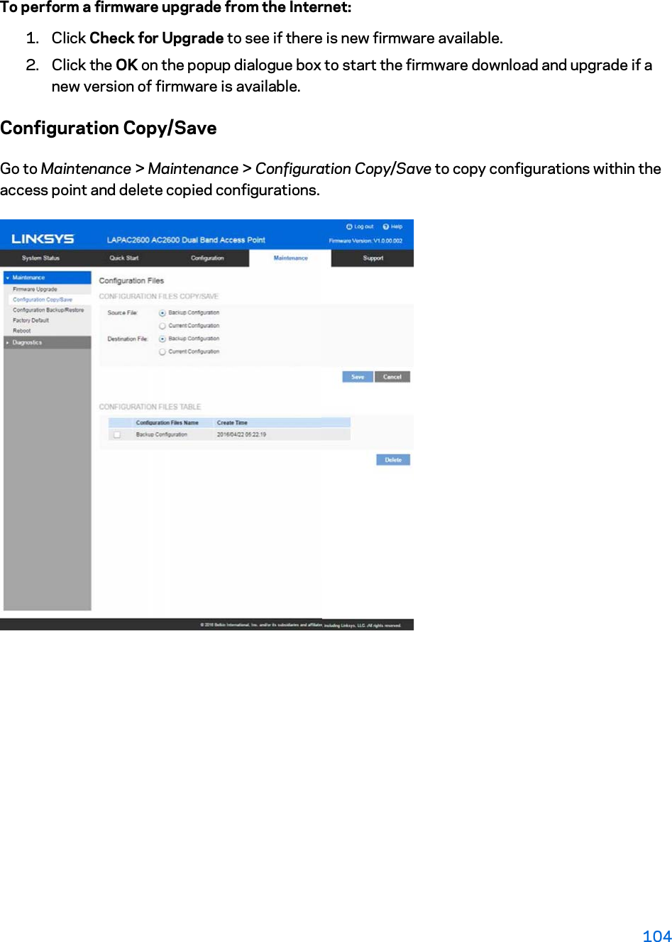
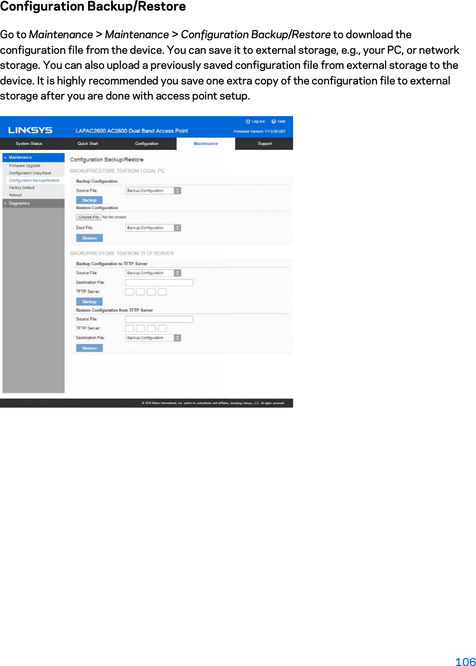
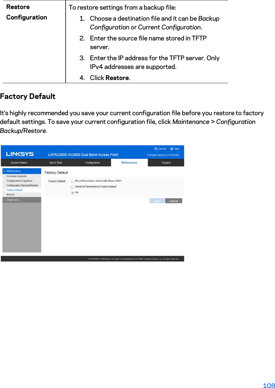
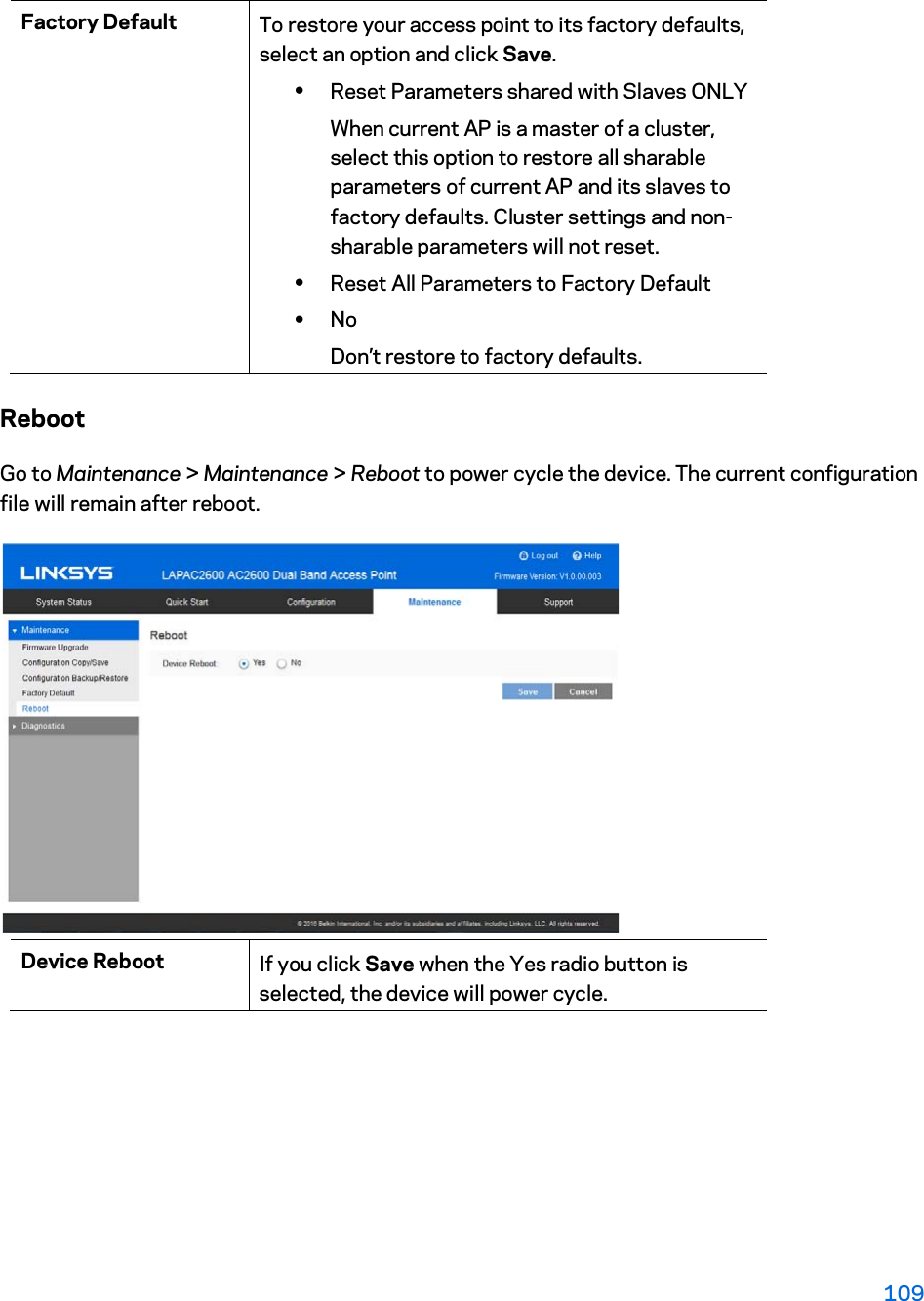
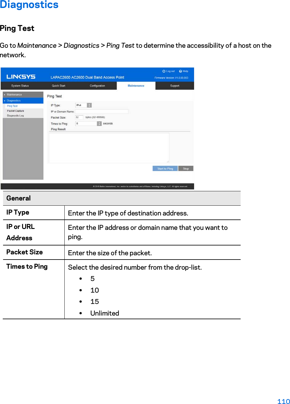
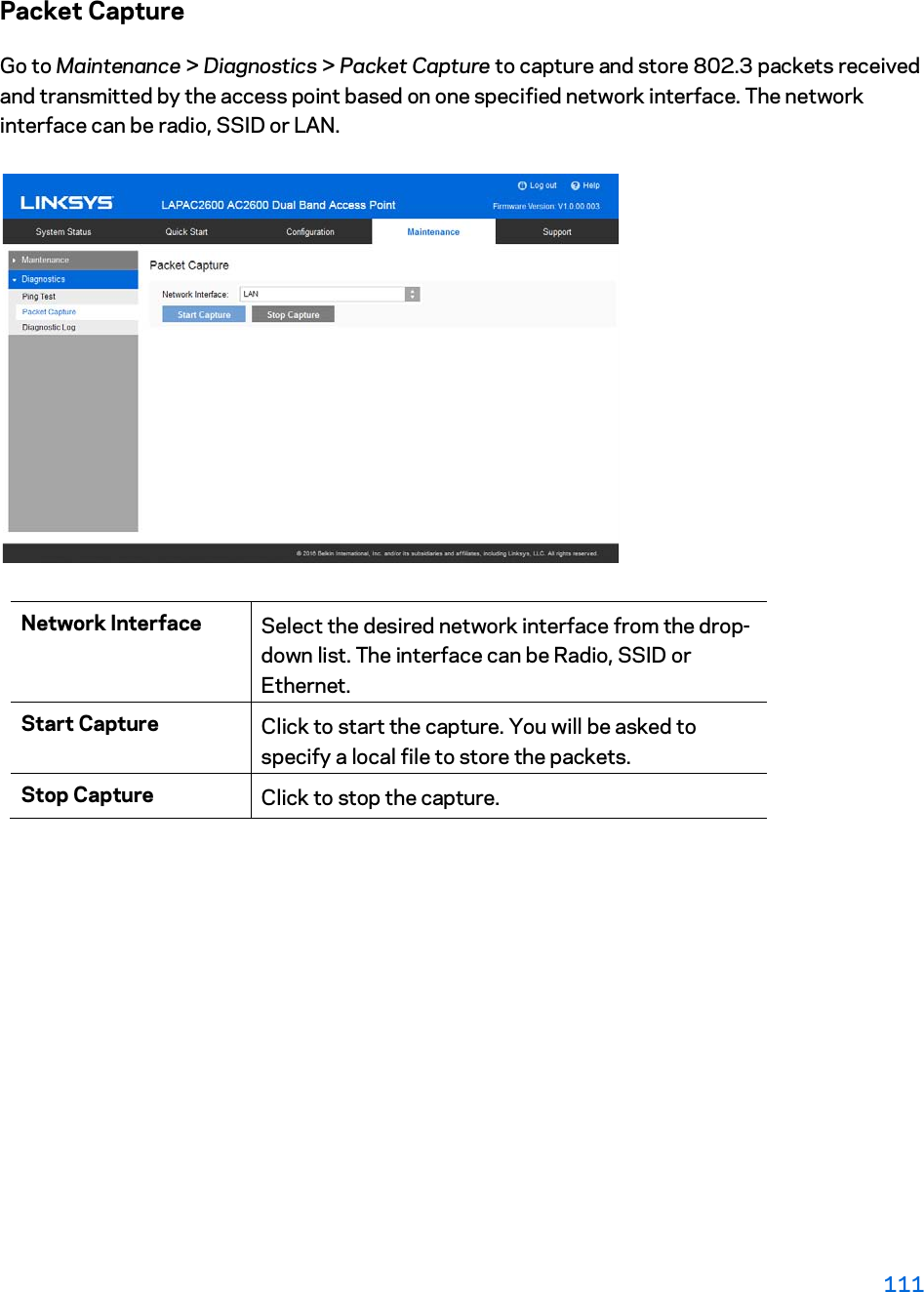
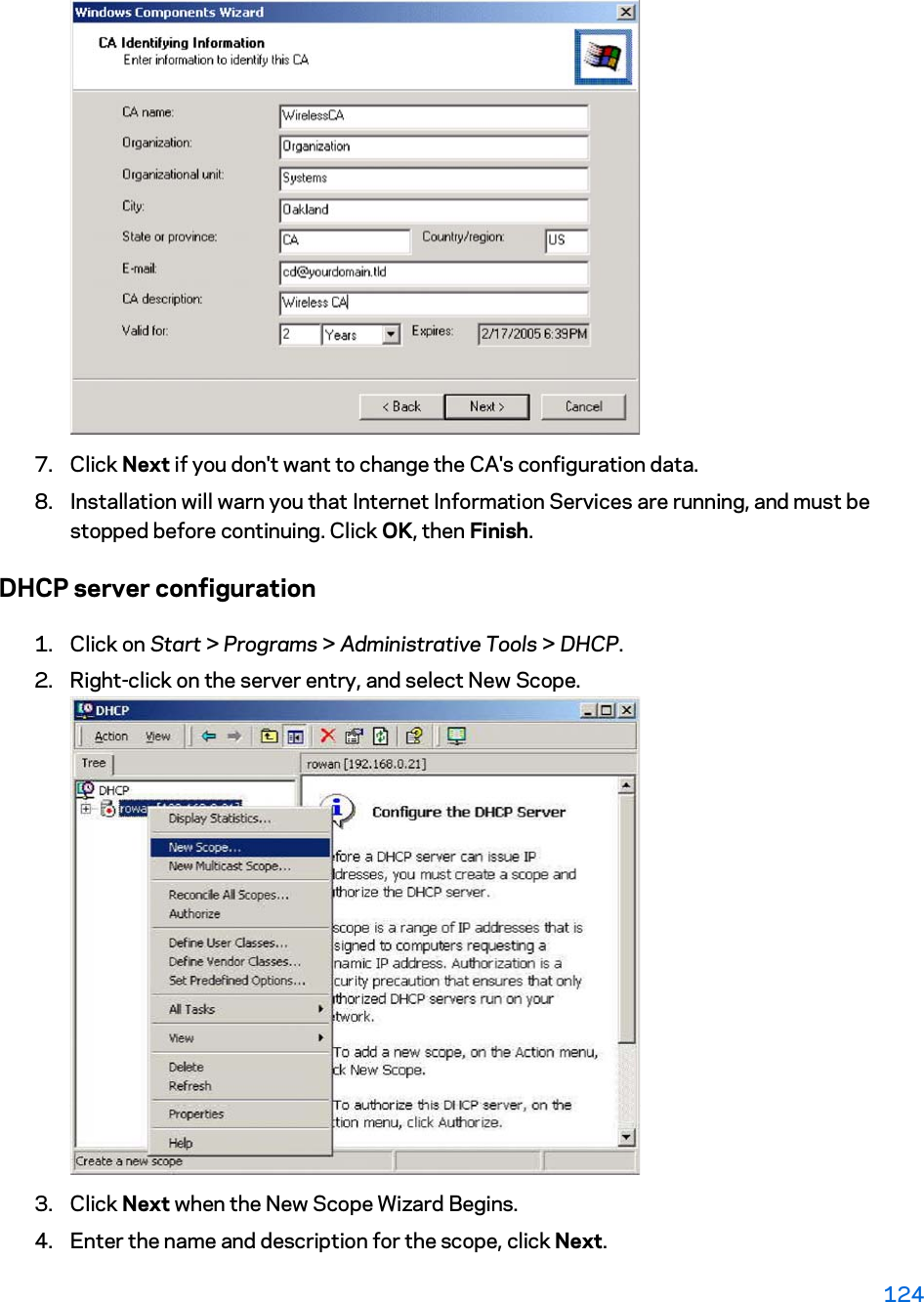
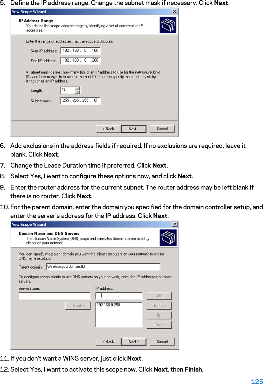
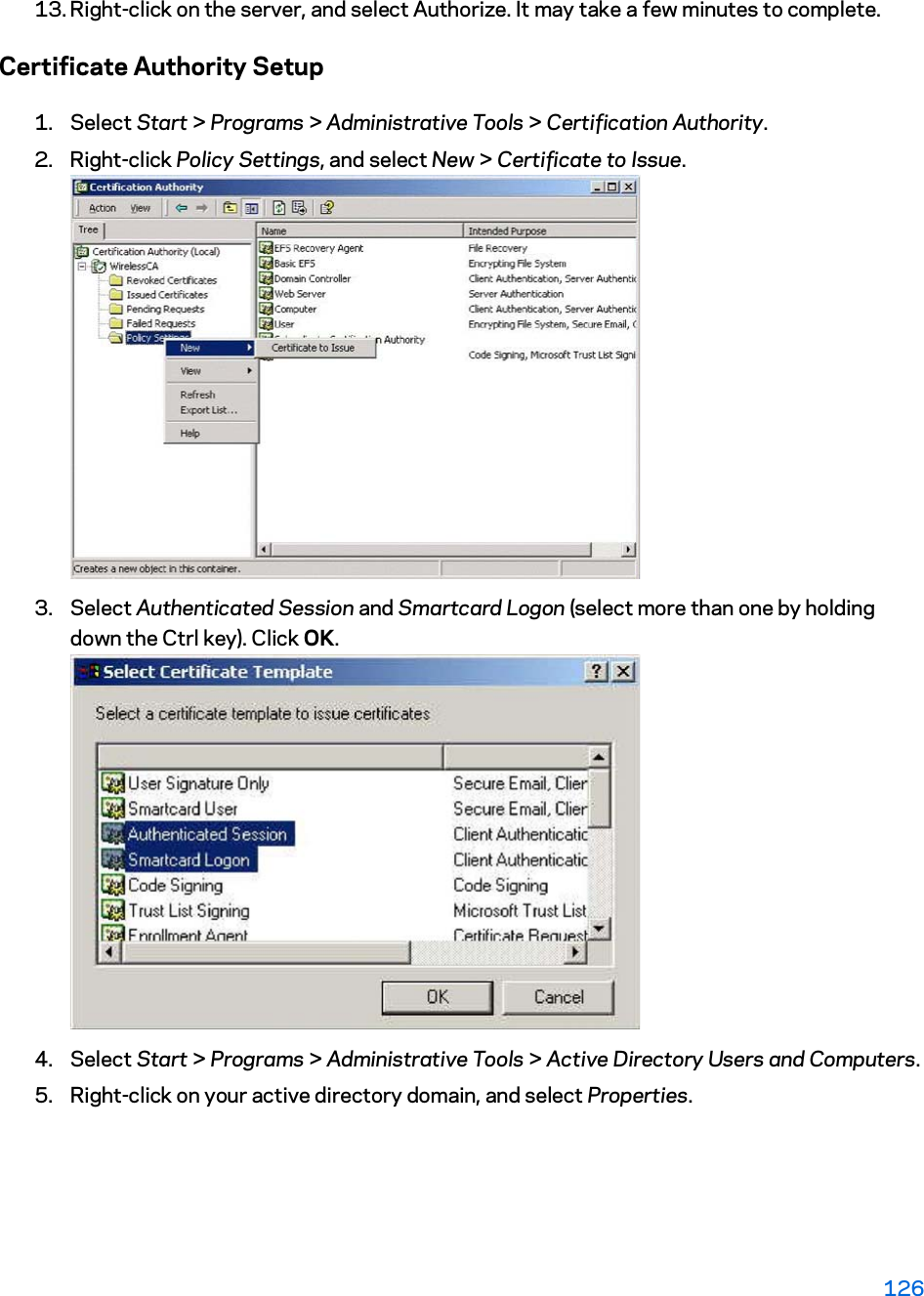
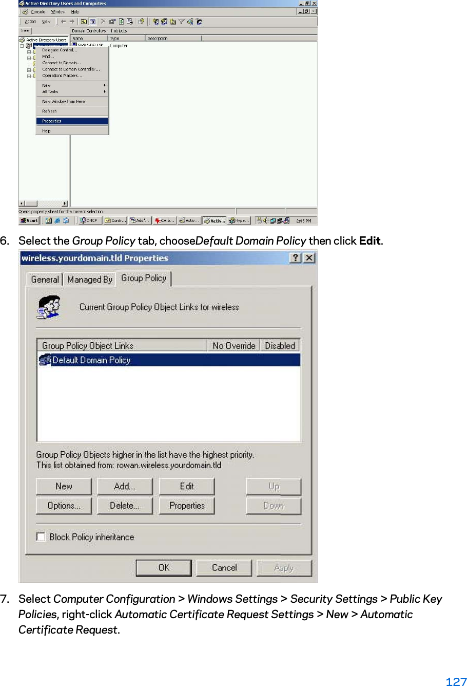
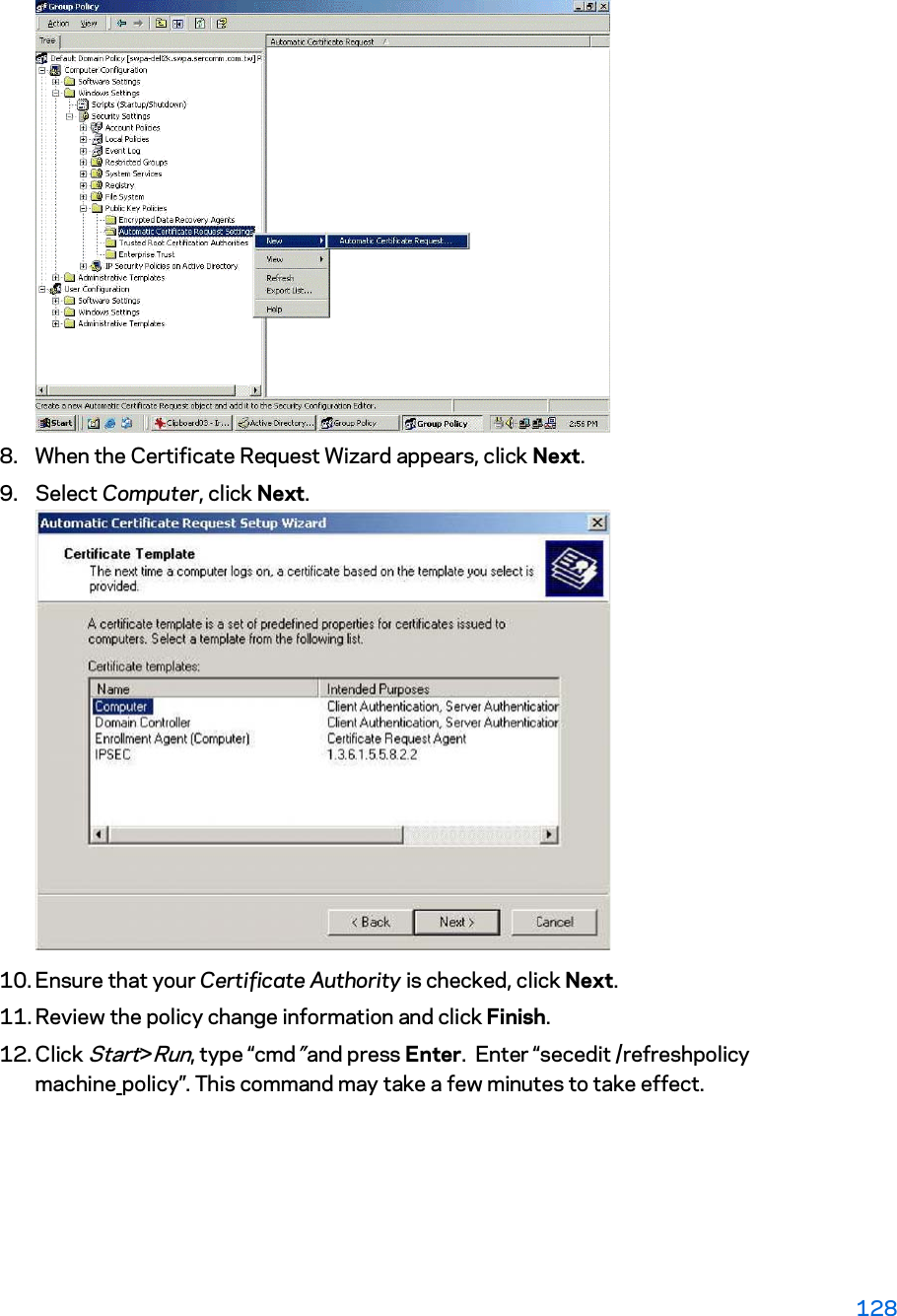
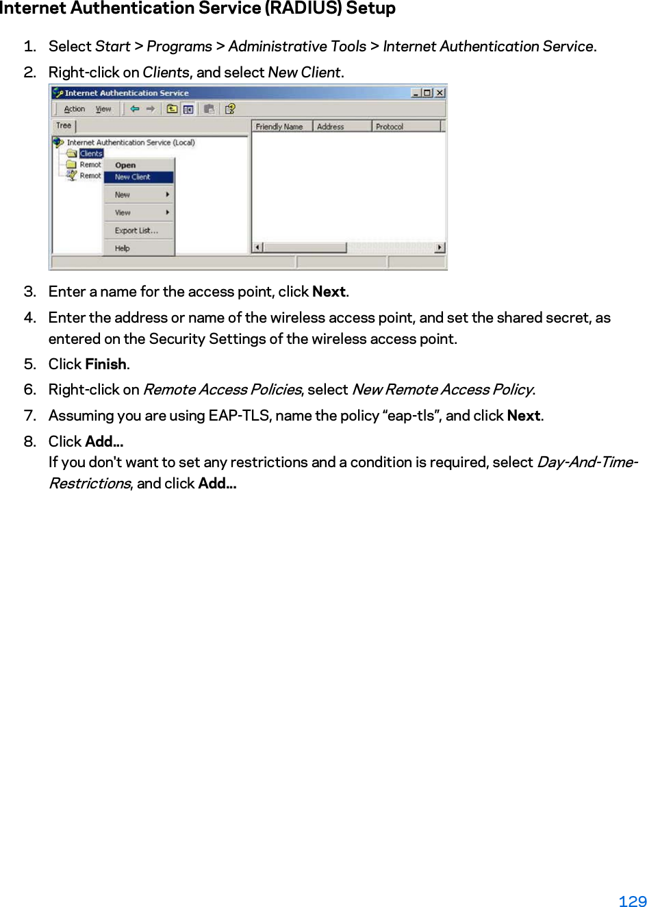
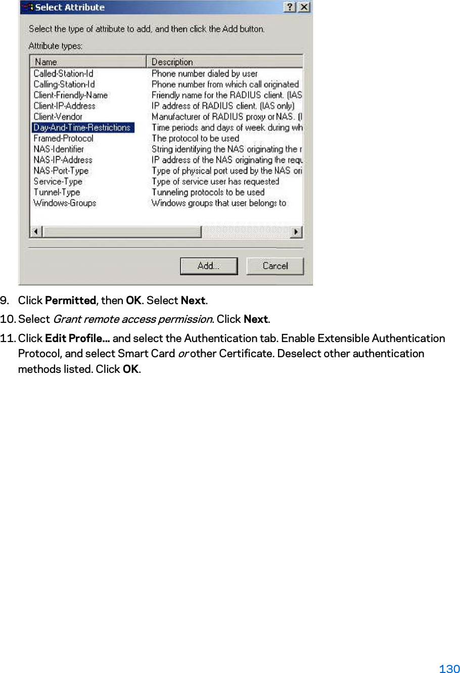
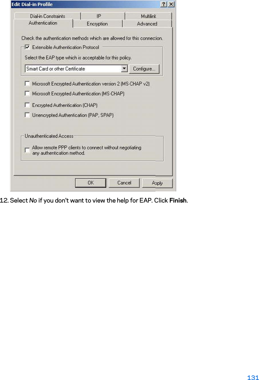
User manual
User manual
Navigation menu
Upload a User Manual
Namespaces
Wiki Guide
HTML
PDF
Info
Views
User Manual
Discussion / Help
Navigation