LINKSYS LAPAC2600 LAPAC2600 Dual Band Access Point User Manual
LINKSYS LLC LAPAC2600 Dual Band Access Point
LINKSYS >
Contents
- 1. User manual statement
- 2. User manual
User manual

User Guide
AC2600 Dual-Band
Wireless Access Point
LAPAC2600
1
Contents
Chapter 1 – Quick Start Guide ........................................................................... 4
Package Contents ................................................................................................................................... 4
Physical Details ........................................................................................................................................ 4
Mounting Guide ........................................................................................................................................ 5
Chapter 2 –Quick Start ......................................................................................... 7
Overview ..................................................................................................................................................... 7
Setup Using a Web Browser ................................................................................................................ 7
Setup Wizard ............................................................................................................................................. 9
Chapter 3 – Configuration ................................................................................ 13
Administration ....................................................................................................................................... 13
LAN ............................................................................................................................................................ 24
Wireless .................................................................................................................................................... 30
Captive Portal ........................................................................................................................................ 64
ACL ............................................................................................................................................................ 76
Cluster ...................................................................................................................................................... 83
Chapter 4 - System Status .............................................................................. 92
Status ....................................................................................................................................................... 92
Chapter 5 – Maintenance ................................................................................103
Maintenance ........................................................................................................................................ 103
Diagnostics .......................................................................................................................................... 110
Appendix A - Troubleshooting .......................................................................113
Overview ............................................................................................................................................... 113
General Problems .............................................................................................................................. 113
Appendix B - About Wireless LANs ..............................................................115
Overview ............................................................................................................................................... 115
Wireless LAN Terminology ............................................................................................................. 115
2
Appendix C - PC and Server Configuration ..............................................119
Overview ............................................................................................................................................... 119
Using WEP ............................................................................................................................................ 119
Using WPA2-PSK .............................................................................................................................. 120
Using WPA2-Enterprise .................................................................................................................. 120
802.1x Server Setup (Windows 2000 Server) ....................................................................... 122
802.1x Client Setup on Windows XP ......................................................................................... 132
Using 802.1x Mode (without WPA) ............................................................................................. 139
3

Chapter 1 --- Quick Start Guide
Package Contents
xLinksys Wireless Access Point
xQuick Start Guide
xEthernet Cable
xAC Power Adapter
xCD with Documentation
xMounting Bracket
xMounting Kit
xCeiling Mount Back Plate
xDrilling Layout Template
Physical Details
LED behavior
LED Color Activity Status
Green Blinking System is booting.
Solid System is normal; no wireless devices connected.
Blue Blinking Software upgrade in process.
Solid System is normal; at least one wireless device connected.
Red Solid
Booting process or update failed; hard reset or service
required.
Ports and Button
Power Port—Connect the AC power adapter to this port.
Note—Use only the adapter that came with your access point.
Ethernet Port 1—Use an RJ45 (CAT5e or better) cable to connect the LAPAC2600 to network
devices such as routers, switches and computers. This port supports PoE+ (IEEE 802.3at). You
may use the port to power LAPAC2600 by using PoE+ switch or injector.
4
Note—System power consumption is over 15W. Make sure your PoE switch or injector is
803.2at-capable (PoE+) and provides sufficient power. If your PoE switch or injector is
not 802.3at-capable, use the provided power adapter. If the PoE and AC power adapters
are connected to the LAPAC2600 at the same time, the device will get power from PoE.
Ethernet Port 2—This is a non-PoE Ethernet port. It can be used instead of Ethernet port 1 but
requires an AC power adapter.
Note—LAG (Link Aggregation) is enabled by default on Ethernet Port 1 and 2. Refer to
your switch configuration guide, and enable one LAG with LACP (802.3ad Link
Aggregation Control Protocol) on the switch if you intend to plug two Ethernet cables into
switch. In this configuration, it is highly recommended that AC power and PoE be used in
tandem in case of support power failure and/or link failure. If your switch does not support
LAG, you can only use one Ethernet port at a time on your LAPAC2600.
Reset Button—Press and hold this button for less than 15 seconds to power cycle device. Press
and hold for longer than 15 seconds to reset the device to factory default settings.
Mounting Guide
To avoid overheating, do not install your access point if ambient temperatures exceed 104°F
(40°C). Install on a flat, stable surface, near the center of your wireless coverage area making
sure not to block vents on the sides of the device enclosure.
Wall Installation
1. Position drilling layout template at the desired location.
2. Drill four screw holes on the mounting surface. If your Ethernet cable is routed behind the
wall, mark Ethernet cable hole as well.
3. Secure the mounting bracket on the wall with anchors and screws.
4. If your Ethernet cable is routed behind the wall, cut or drill the Ethernet cable hole you
marked in Step 2. Feed the Ethernet cable through the hole.
5. Connect the Ethernet cable and/or AC power adapter to your device.
6. Slide the device into the bracket. Turn clockwise until it locks into place.
5
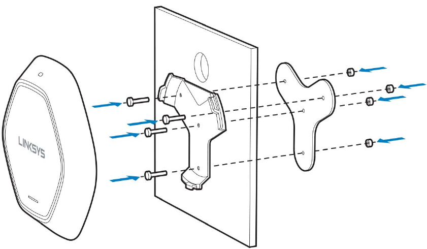
Ceiling Installation
1. Select ceiling tile for mounting and remove tile.
2. Position drilling layout template at the desired location.
3. Drill four screw holes and Ethernet cable hole on the surface of ceiling tile.
4. Place back plate on the opposite side of ceiling tile. Secure mounting bracket to the ceiling
tile with flathead screw and nut. Route the Ethernet cable through the Ethernet cable
hole.
5. Replace tile in ceiling.
6. Connect the Ethernet cable and/or AC power adapter to your device
7. Slide the device into the bracket. Turn access point clockwise until it locks.
IMPORTANT—Improper or insecure mounting could result in damage to the device or personal
injury. Linksys is not responsible for damages caused by improper mounting.
6

Chapter 2 ---Quick Start
Overview
This chapter describes the setup procedure to connect the wireless access point to your LAN, and
configure it as an access point for your wireless stations.
Wireless stations may also require configuration. For details, see Appendix C - Wireless Station
Configuration (p. 119).
The wireless access point can be configured using a web browser.
Note—Licenses and notices for third party software used in this product may be viewed on
http://support.linksys.com/en-us/license. Please contact http://support.linksys.com/en-
us/gplcodecenter for questions about GPL source code requests.
Setup Using a Web Browser
Your browser must support JavaScript. The configuration program has been tested on the
following browsers:
xFirefox 3.5 or later, Chrome 8 or later, Safari 5 or later
xInternet Explorer 8 or later
Setup Procedure
Make sure device is powered on before you continue setup. If LED light is off, check that AC
power adapter, or PoE cable, is properly connected on both ends.
Access device’s browser-based setup:
1. Use the included cable to connect the access point to your network via a network switch
or router.
2. Open a web browser on a computer connected to your network. Enter the IP address of
your access point. By factory default, the IP address will be assigned by a DHCP server
(usually the network router). If there is no DHCP server on your network, the default IP
address is 192.168.1.252/255.255.255.0.
Note—Use a computer hardwired to the same network as your access point for browser-based
setup access. Access to browser-based setup via Wi-Fi is disabled by default.
3. Type in default username: “admin”, and password: “admin”.
7
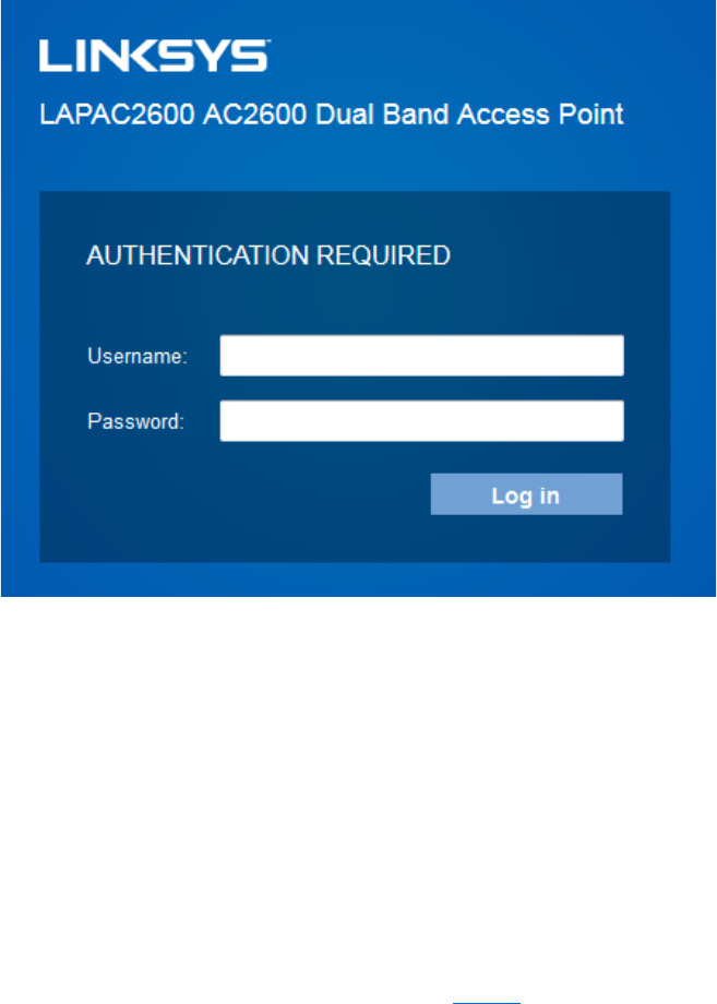
4. Click Log in to launch the browser-based setup and follow the on-screen instructions.
If you can't connect:
It is likely that your PC’s IP address is incompatible with the wireless access point’s IP address.
This can happen if your LAN does not have a DHCP Server. If there is no DHCP server in your
network, the access point will fall back to its default IP address: 192.168.1.252, with a network
mask of 255.255.255.0.
Or, if your PC’s IP address is not compatible with this, you must change your PC’s IP address to an
unused value in the range 192.168.1.1 ~ 192.168.1.254, with a network mask of
255.255.255.0. See Appendix A - Windows TCP/IP (p. 113) for details for this procedure.
8
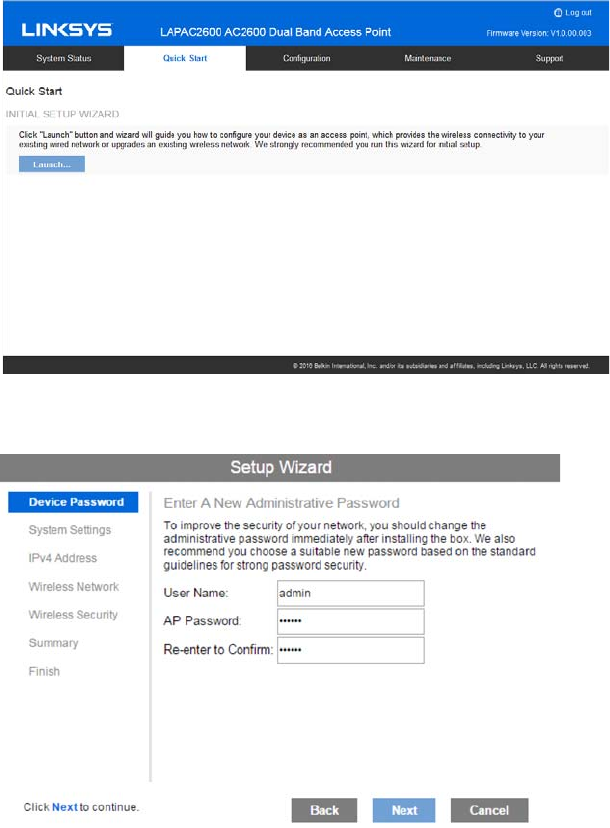
Setup Wizard
If you are setting up the access point as a standalone device, run the Setup Wizard. If the access
point will be part of a cluster – master or slave - go to Configuration > Cluster > Settings & Status
page instead.
1. Click the Quick Start tab on the main menu.
2. On the first screen, click Launch...
3. Set the password on the Device Password screen, if desired.
4. Configure the time zone, date and time for the device on System Settings screen.
9
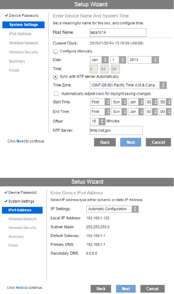
5. On the IPv4 Address screen configure the IP address of the device (
Static
or
Automatic
)
then click Next.
10
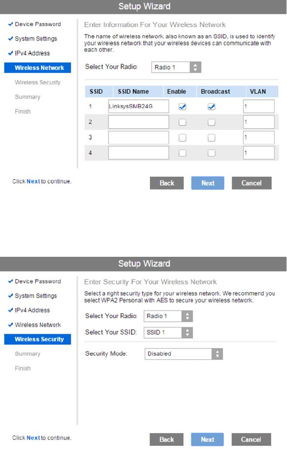
6. Set the SSID information on the Wireless Network screen. Click Next. If you want to
configure more than four SSIDs, go to Configuration > Wireless > Basic Settings. The
access point supports up to eight SSIDs per radio.
7. On the Wireless Security Screen, configure the wireless security settings for the device.
Click Next. If you are looking for security options that are not available in the wizard, go to
Configuration > Wireless Security page. The access point supports more sophisticated
security options there.
11
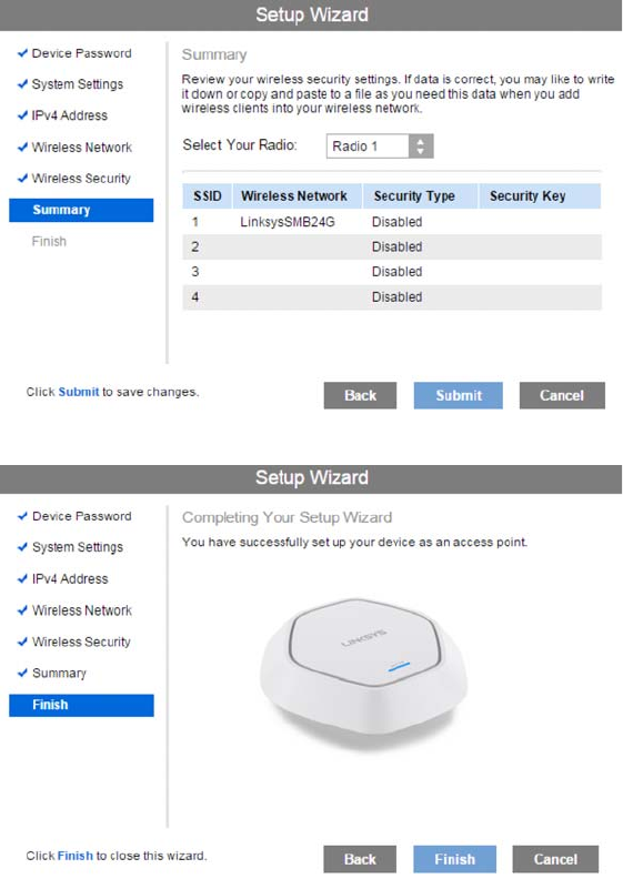
8. On the Summary screen, check the data to make sure they are correct and then click
Submit to save the changes.
9. Click Finish to leave the wizard.
12
Chapter 3 --- Configuration
Administration
User Accounts
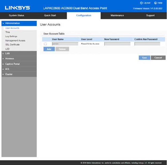
Go to Configuration > Administration and select User Accounts to manage user accounts. The
access point supports up to five users: one administrator and four normal users.
13
User Account Table
User Name Enter the User Name to connect to the access point’s admin
interface. User Name is effective once you save settings.
User Name can include up to 63 characters. Special
characters are allowed.
User Level Only administrator account has Read/Write permission to
the access point’s admin interface. All other accounts have
Read Only permission.
New Password Enter the Password to connect to the access point’s admin
interface.
Password must be between 4 and 63 characters. Special
characters are allowed.
Confirm New
Password
Re-enter password.
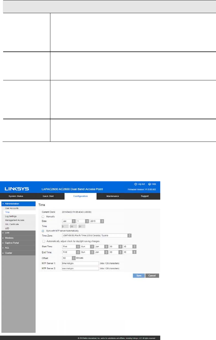
Time
Go to Configuration > Administration and select Time to configure system time of the device.
14

Time
Current Time Display current date and time of the system.
Manually Set date and time manually.
Automatically When enabled (default setting) the access point will get the
current time from a public time server.
Time Zone Choose the time zone for your location from the drop-down
list. If your location observes daylight saving time, enable
Automatically adjust clock for daylight saving changes.
Start Time Specify the start time of daylight saving.
End Time Specify the end time of daylight saving.
Offset Select the adjusted time of daylight saving.
NTP
NTP Server 1 Enter the primary NTP server. It can be an IPv4 address or a
domain name.
Valid characters include alphanumeric characters, "_", "-"
and ".".Maximum length is 64 characters.
NTP Server 2 Enter the secondary NTP server. It can be an IPv4 address
or a domain name.
Valid characters include alphanumeric characters, "_", "-"
and ".".Maximum length is 64 characters.
15
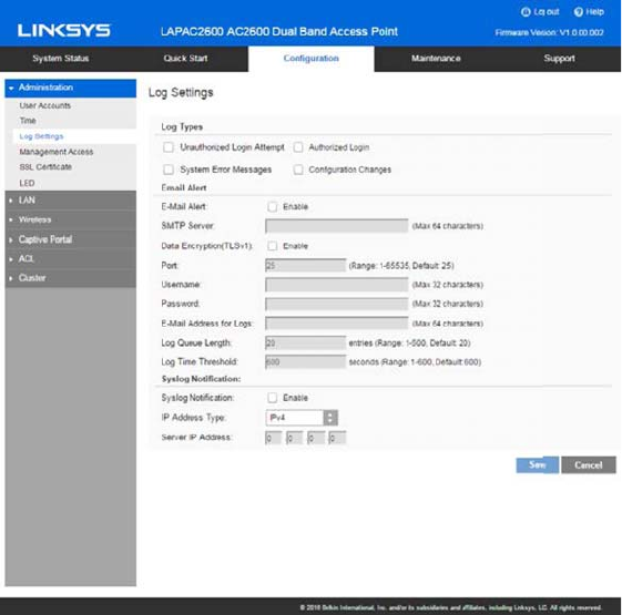
Log Settings
Go to Configuration > Administration and select Log Settings to configure logs. Logs record
various types of activity on the access point. This data is useful for troubleshooting, but enabling
all logs will generate a large amount of data and adversely affect performance.
16

Log Types
Log Types Select events to log. Checking all options increase the
size of the log, so enable only events you believe are
required.
Email Alert
Email Alert Enable email alert function.
SMTP Server Enter the e-mail server that is used to send logs. It can
be an IPv4 address or a domain name.
Valid characters include alphanumeric characters, "_", "-
" and ".". Maximum length is 64 characters.
Data Encryption Enable if you want to use data encryption.
Port Enter the port for the SMTP server. The port is a value
from 1 to 65535 and default is 25.
Username Enter the Username to login to your SMTP server.
The Username can include up to 32 characters. Special
characters are allowed.
Password Enter the Password to login to your SMTP server.
The Password can include up to 32 characters. Special
characters are allowed.
Email Address for
Logs
Enter the email address the log messages are to be
sent to.
Valid characters include alphanumeric characters, "_", "-
", "." and "@". Maximum length is 64 characters.
Log Queue Length Enter the length of the queue: up to 500 log messages.
The default is 20 messages. When messages reach the
set length the queue will be sent to the specified email
address.
Log Time
Threshold
Enter the time threshold (in seconds) used to check if
the queue is full. It’s a value from 1 to 600 and default
is 600 seconds.
Syslog
Syslog Notification Enable Syslog notification.
IP Type Select the IP type of the syslog server: IPv4 or IPv6.
Server IP Address Enter the IPv4 or IPv6 address of syslog server here.
17
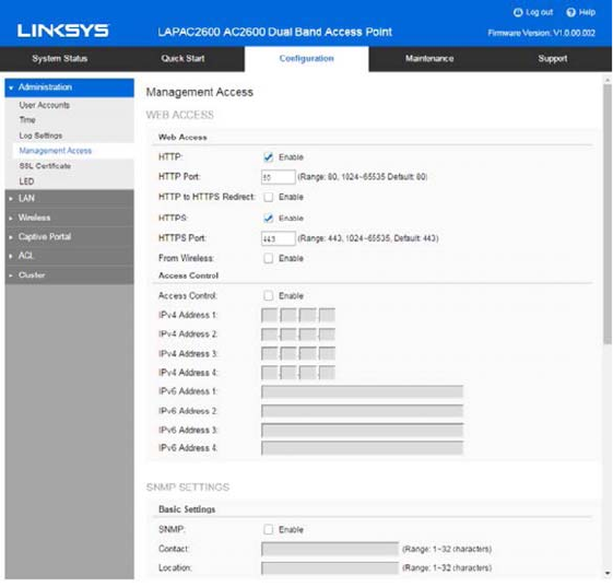
Management Access
Go to Configuration > Administration and select
Management Access
page to configure the
management methods of the access point.
18

Web Access
HTTP HTTP (HyperText Transfer Protocol) is the standard for
transferring files (text, graphic images and other
multimedia files) on the World Wide Web.
Enable to allow Web access by HTTP protocol.
HTTP Port Specify the port for HTTP. It can be 80 (default) or from
1024 to 65535.
HTTP to HTTPS
Redirect
Enable to redirect Web access of HTTP to HTTPS
automatically.
This field is available only when HTTP access is
disabled.
HTTPS HTTPS (Hypertext Transfer Protocol Secure) can
provide more secure communication with the SSL/TLS
protocol, which support data encryption to HTTP
clients and servers.
Enable to allow Web access by HTTPS protocol.
HTTPS Port Specify the port for HTTPS. It can be 443 (default) or
from 1024 to 65535.
From Wireless Enable wireless devices to connect to access point’s
admin page. Disabled by default.
Access Control By default, no IP addresses are prohibited from
accessing the device’s admin page. You can enable
access control and enter specified IP addresses for
access. Four IPv4 and four IPv6 addresses can be
specified.
SNMP Settings
SNMP Simple Network Management Protocol (SNMP) is a
network monitoring and management protocol.
Enable or disable SNMP function here. Disabled by
default.
Contact Enter contact information for the access point.
The contact includes 1 to 32 characters. Special
characters are allowed.
19

Location Enter the area or location where the access point
resides.
The location includes 1 to 32 characters. Special
characters are allowed.
SNMP v1/v2 Settings
Get Community Enter the name of Get Community. Get Community is
used to read data from the access point and not for
writing data into the access point.
Get Community includes 1 to 32 characters. Special
characters are allowed.
Set Community Enter the name of Set Community. Set Community is
used to write data into the access point.
The Set Community includes 1 to 32 characters.
Special characters are allowed.
SNMP v3 Settings
SNMP v3 Settings Configure the SNMPv3 settings if you want to use
SNMPv3.
Username: Enter the username. It includes 0 to 32
characters. Special characters are allowed.
Authentication Protocol: None or HMAC-MD5.
Authentication Key: 8 to 32 characters. Special
characters are allowed.
Privacy Protocol: None or CBC-DES.
Privacy Key: 8 to 32 characters. Special characters are
allowed.
Access Control
Access Control When SNMP is enabled, any IP address can connect to
the access point MIB database through SNMP. You can
enable access control to allow specified IP addresses.
Two IPv4 and two IPv6 addresses can be specified.
SNMP Trap
Trap Community Enter the Trap Community server. It includes 1 to 32
characters. Special characters are allowed.
Trap Destination Two Trap Community servers are supported: can be
IPv4 or IPv6.
20
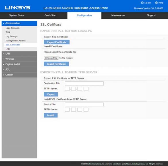
SSL Certificate
Go to Configuration > Administration and select SSL Certificate to manage the SSL certificate
used by HTTPS.
21

Export/Restore to/from Local PC
Export SSL
Certificate
Click to export the SSL certificate.
Install Certificate Browse to choose the certificate file. Click Install
Certificate.
Export to TFTP Server
Destination File Enter the name of the destination file.
TFTP Server Enter the IP address for the TFTP server. Only
support IPv4 address here.
Export Click to export the SSL certificate to the TFTP
server.
Restore from TFTP Server
Source File Enter the name of the source file.
TFTP Server Enter the IP address for the TFTP server. Only
support IPv4 address here.
Install Click to install the file to the device.
22
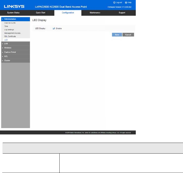
LED
Go to Configuration > Administration and select LED to enable or disable the LED on the top
cover of LACAP2600.
LED
LED Display If disabled, the LED will be off even when the access
point is working. By default, LED is enabled (on).
23
LAN
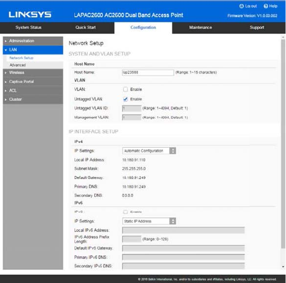
Network Setup
Go to Configuration > LAN > Network Setup to configure basic device settings, VLAN settings
and settings for the LAN interface, including static or dynamic IPv4/IPv6 address assignment.
24

TCP/IP
Host Name Assign a host name to this access point. Host name consists of 1 to
15 characters. Valid characters include A-Z, a-z, 0-9 and -. Character
cannot be first and last character of hostname and hostname cannot
be composed of all digits.
VLAN Enables or disables VLAN function.
Untagged
VLAN
Enables or disables VLAN tagging. If enabled (default), traffic from the
LAN port is untagged when the following conditions are met: 1) VLAN
ID is equal to Untagged VLAN ID and 2) untagged traffic can be
accepted by LAN port. If disabled, traffic from the LAN port is always
tagged and only tagged traffic can be accepted from LAN port.
By default, all traffic on the access point uses VLAN 1, the default
untagged VLAN. All traffic will be untagged until you disable the
untagged VLAN, change the untagged traffic VLAN ID, or change the
VLAN ID for a SSID.
Untagged
VLAN ID
Specifies a number between 1 and 4094 for the untagged VLAN ID.
The default is 1. Traffic on the VLAN that you specify in this field is
not be tagged with a VLAN ID when forwarded to the network.
Untagged VLAN ID field is active only when untagged VLAN is
enabled.
VLAN 1 is the default for both untagged VLAN and management
VLAN.
Management
VLAN
The VLAN associated with the IP address you use to connect to the
access point. Provide a number between 1 and 4094 for the
Management VLAN ID. The default is 1.
IPv4/v6
IP Settings Select Automatic Configuration or Static IP Address.
IP Address Enter an unused IP address from the address range used on your LAN.
Subnet Mask Enter the subnet mask for the IP address above.
Default
Gateway
Enter the gateway for the IP address above.
Primary DNS Enter the DNS address.
Secondary
DNS
Optional. If entered, this DNS will be used if the Primary DNS does not
respond.
25
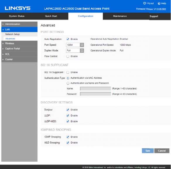
Advanced
Go to Configuration > LAN > Advanced to configure advanced network settings of the access
point.
26

Port Settings
Auto
Negotiation
If enabled, Port Speed and Duplex Mode will become grey
and cannot be configured. If disabled, Port Speed and
Duplex Mode can be configured.
Note—LAG (Link Aggregation) is enabled by default on
Ethernet port 1 and 2. It is highly recommended you keep
auto negotiation enabled on both sides of an aggregate
link. Enable LACP (Link Aggregation Control Protocol) on
this specific LAG interface when you create LAG interface
on switch. If you have to disable auto negotiation, ensure
link speed and duplex (Full) are identical on both sides.
Operational
Auto
Negotiation
Current Auto Negotiation mode of the Ethernet port.
Port Speed Select the speed of the Ethernet port. Available only when
Auto Negotiation is disabled. The option can be 10M, 100M
or 1000M (default).
Operational
Port Speed
Displays the current port speed of the Ethernet port.
Duplex Mode Select the duplex mode of the Ethernet port. Available only
when Auto Negotiation is disabled. The option can be Half
or Full (default).
Operational
Duplex Mode
Displays the current duplex mode of the Ethernet port.
Flow Control Enable or disable flow control of the Ethernet port.
27

802.1x Supplicant
802.1x
Supplicant
Enable if your network requires this access point to use
802.1X authentication in order to operate.
Authentication This feature supports following two kinds of authentication:
xAuthentication via MAC Address
Select this if you want to use MAC Address for
authentication.
The access point uses lowercase MAC address for
Name and Password, like xxxxxxxxxxxx.
xAuthentication via Name and Password
Select this if you want to use name and password for
authentication.
Name - Enter the login name. The name includes 1 to 63
characters. Special characters are allowed.
Password - Enter the desired login password. The
password includes 4 to 63 characters. Special
characters are allowed.
Discovery Settings
Bonjour Enable if administrator wants the access point to be
discovered by Bonjour enabled devices automatically. If
VLAN is enabled, the discovery packets will be sent out via
management VLAN only. The access point supports http
and https services.
LLDP Enable if administrator wants the access point to be
discovered by switch by LLDP protocol. Information such as
product name, device name, firmware version, IP address,
MAC address and so on will be advertised.
LLDP-MED Enable if administrator wants the access point to be
discovered by switch by LLDP-MED protocol. Information
such as product name, device name, firmware version, IP
address, MAC address and so on will be advertised.
28

IGMP/MLD Snooping
IGMP
Snooping
IGMP (Internet Group Management Protocol) is a
communications protocol used by hosts and adjacent
routers on IP networks to establish multicast group
memberships. IGMP is an integral part of IP multicast.
IGMP snooping streamlines multicast traffic handling by
examining (snooping) IGMP membership report messages
from interested hosts, multicast traffic is limited to the
subset of ports on which the hosts reside.
IGMP snooping is enabled by default in the access point
The access point supports IGMPv1, IGMPv2 and IGMPv3 in
IGMP Snooping.
MLD Snooping MLD (Multicast Listener Discovery) is a component of the
Internet Protocol Version 6 (IPv6) suite. MLD is used by
IPv6 routers for discovering multicast listeners on a
directly attached link, much like IGMP is used in IPv4.
Multicast Listener Discovery (MLD) Snooping provides
multicast containment by forwarding traffic only to those
clients that have MLD receivers for a specific multicast
group (destination address). The access point maintains the
MLD group membership information by processing MLD
reports and generating messages so traffic can be
forwarded to ports receiving MLD reports.
MLD snooping is enabled by default in the access point
The access point supports MLDv1 and MLDv2 in MLD
Snooping.
29
Wireless
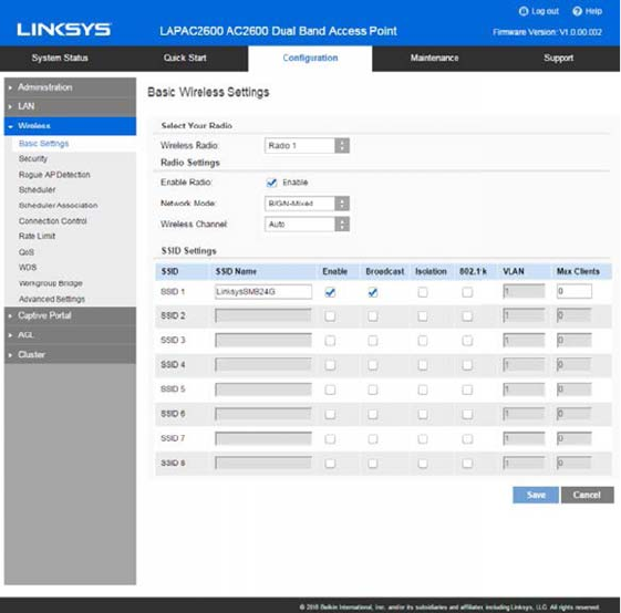
Basic Settings
Go to Configuration > Wireless > Basic Settings to configure your wireless radio and SSIDs.
Advanced wireless settings such as Band Steering, Channel Bandwidth, are on the Advanced
Settings screen.
30

Basic Wireless Settings
Wireless
Radio
Select the wireless radio from the list.
Radio 1 is for 2.4 GHz, and Radio 2 is for 5 GHz.
Enable Radio Enable or disable the wireless radio.
Wireless
Mode
Select the desired option for radio 1:
G only - allow connection by 802.11G wireless stations
only.
N only - allow connection by 802.11N wireless stations
only.
B/G-Mixed - allow connection by 802.11B and G wireless
stations only.
B/G/N-Mixed (Default) - allow connections by 802.11N,
802.11B and 802.11G wireless stations.
Select the desired option for radio 2:
N/A-Mixed - allow connection by 802.11A and N wireless
stations only.
N only - allow connection by 802.11N wireless stations
only.
AC only - allow connection by 802.11AC wireless stations
only.
A/N/AC-Mixed - allow connection by 802.11A, 802.11N
and 802.11AC wireless stations.
Wireless
Channel
Select wireless channel of the radio.
If Auto is selected, the access point will select the best
available channel when device boots up.
If you experience lost connections and/or slow data
transfers, manually change the channel until you find which
channel is best.
31

SSID Settings
SSID Name Enter the desired SSID Name. Each SSID must have a
unique name. The name includes 1 to 32 characters.
Broadcast Enable or disable the broadcast of the SSID.
When the access point does not broadcast its SSID, the
network name is not shown in the list of available networks
on a client station. Instead, you must enter the exact
network name manually into the wireless connection utility
on the client so that it can connect.
Isolation Enable or disable isolation among clients of the SSID. If
enabled, wireless clients cannot communicate with others
in the same SSID.
It is disabled by default.
802.11k Enable or disable 802.11k of the SSID.
The 802.11k protocol provides mechanisms for APs and
clients to measure the available radio resources
dynamically. In an 802.11k enabled network, APs and
clients can send neighbor reports, beacon reports, and link
measurement reports to each other. This allows the APs
and clients to take appropriate connection actions for next
hop if client has weak connection to current AP.
VLAN ID Enter the VLAN ID of the SSID.
Used to tag packets which are received from the wireless
clients of the SSID and sent from Ethernet or WDS
interfaces.
Applicable only when VLAN function is enabled. VLAN
function can be configured in Configuration -> LAN ->
Network Setup screen.
Max Clients Enter the number of clients that can connect to the SSID.
The range is from 0 to 32 and 0 means no limit.
32
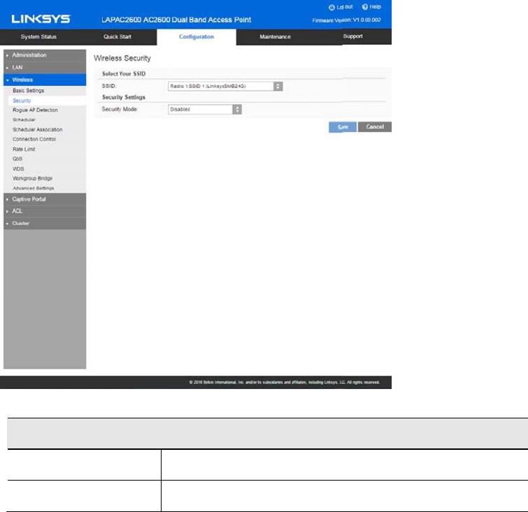
Security
Go to Configuration > Wireless > Security to configure security settings of SSIDs to provide data
protection over the wireless network.
Security
Select SSID Select the desired SSID from the drop-down list.
Security Mode Select the desired security method from the list.
Security Mode
xDisabled - No security. Anyone using the correct SSID can connect to your network.
xWEP - The 802.11b standard. Data is encrypted before transmission, but the encryption
system is not very strong.
xWPA2-Personal - This is a further development of WPA-PSK, and offers even greater
security, using the AES (Advanced Encryption Standard) method.
xWPA/WPA2-Personal - This method, sometimes called Mixed Mode, allows clients to use
either WPA-Personal (with TKIP) or WPA2-Personal (with AES).
33
xWPA2-Enterprise - Requires a RADIUS Server on your LAN to provide the client
authentication according to the 802.1x standard. Data transmissions are encrypted using
the WPA2 standard.
If this option is selected:
-This access point must have a client login on the RADIUS Server.
-Each user must authenticate on the RADIUS Server. This is usually done using
digital certificates.
-Each user's wireless client must support 802.1x and provide the RADIUS
authentication data when required.
-All data transmission is encrypted using the WPA2 AES standard. Keys are
automatically generated, so no key input is required.
xWPA/WPA2-Enterprise – This method, sometimes called Mixed Mode, allows clients to use
either WPA-Enterprise (with TKIP) or WPA2-Enterprise (with AES).
xRADIUS - RADIUS mode utilizes RADIUS server for authentication and dynamic WEP key
generation for data encryption.
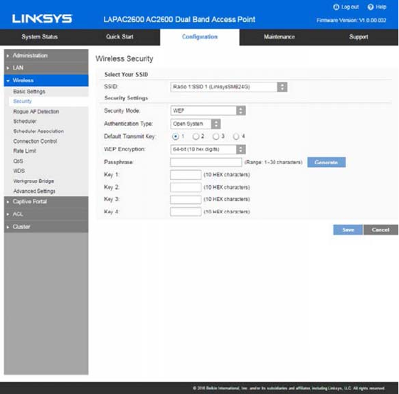
WEP
This is the 802.11b standard. Data is encrypted before transmission, but the encryption system
is not very strong.
34

WEP
Authentication Select Open System or Shared Key. All wireless stations
must use the same method.
Default
Transmit Key
Select a transmit key.
WEPEncryption Select an encryption option, and ensure your wireless
stations have the same setting:
64-Bit Encryption - Keys are 10 Hex characters.
128-Bit Encryption - Keys are 26 Hex characters.
Passphrase Generate a key or keys, instead of entering them directly.
Enter a word or group of printable characters in the
Passphrase box and click the Generate button to
automatically configure the WEP key. It consists of 1 to
30 characters.
Key Value Enter a key in hexadecimal format.
Note—Due to hardware limitations, one set of WEP key is
supported per radio.
35
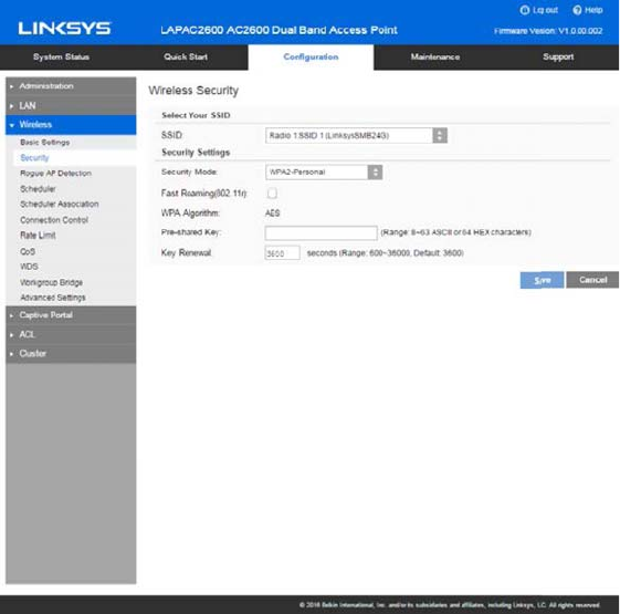
WPA2-Personal
This is a further development of WPA-Personal, and offers even greater security.
36

WPA2-Personal
Fast
Roaming(802.11r)
Enable or disable Fast Roaming (802.11r) .
Fast Roaming (802.11r) minimizes the delay when a
voice client transitions from one BSS to another within
the same ESS. Fast BSS Transition establishes
security and QoS states at the target AP before or
during a re-association. This minimizes the time
required to resume data connectivity when a BSS
transition happens.
Important Points to Remember:
yFast Roaming (802.11r) is operational only if the
wireless client has support for 802.11r
standard. If the client does not have support for
802.11r standard, it falls back to normal WPA2
authentication method.
yIf Fast Roaming (802.11r) is enabled, some
clients without 802.11r supported may fail to
connect to the network.
yOnly one SSID of the AP can be enabled with
Fast Roaming (802.11r).
WPA Algorithm The encryption method is AES. Wireless stations must
also use AES.
Pre-shared Key Enter the key value. It is 8 to 63 ASCII characters or
64 HEX characters. Other wireless stations must use
the same key.
Key Renewal Specify the value of Group Key Renewal. It’s a value
from 600 to 36000 and default is 3600.
WPA automatically changes secret keys after a certain
period of time. The group key interval is the period of
time in between automatic changes of the group key,
which all devices on the network share.
Constantly keying the group key protects your
network against intrusion, as the would-be intruder
must cope with an ever-changing secret key.
37
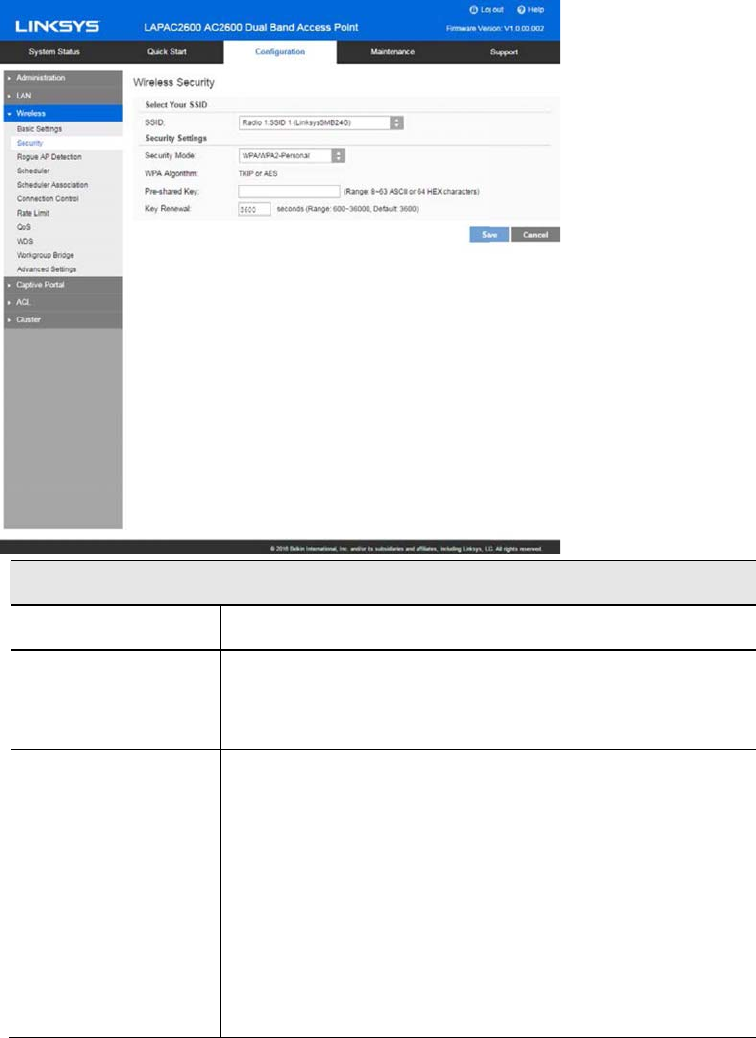
WPA/WPA2-Personal
This method, sometimes called Mixed Mode, allows clients to use either WPA-Personal or WPA2-
Personal.
WPA/WPA2-Personal
WPA Algorithm The encryption method is TKIP or AES.
Pre-shared Key Enter the key value. It is 8 to 63 ASCII characters or
64 HEX characters. Other wireless stations must use
the same key.
Key Renewal Specify the value of Group Key Renewal. It’s a value
from 600 to 36000, and default is 3600.
WPA automatically changes secret keys after a certain
period of time. The group key interval is the period of
time in between automatic changes of the group key,
which all devices on the network share.
Constantly keying the group key protects your
network against intrusion, as the would-be intruder
must cope with an ever-changing secret key.
38
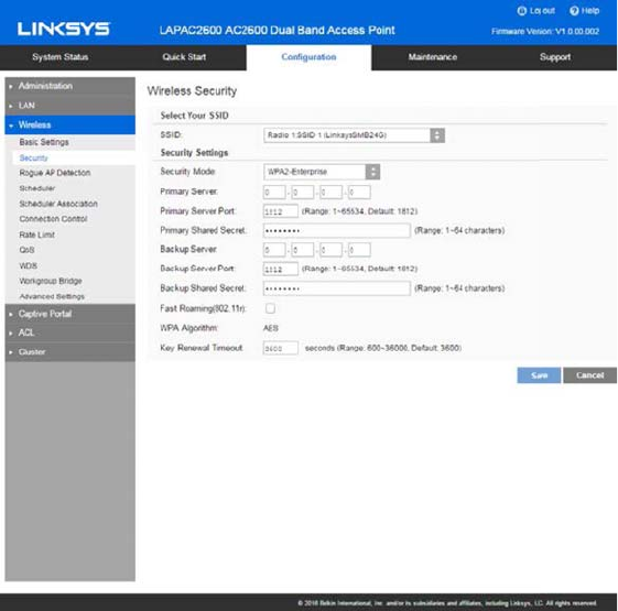
WPA2-Enterprise
This version of WPA2-Enterprise requires a RADIUS Server on your LAN to provide the client
authentication. Data transmissions are encrypted using the WPA2 AES standard.
39

WPA2-Enterprise
Fast Roaming
(802.11r)
Enable or disable Fast Roaming (802.11r).
Fast Roaming (802.11r) minimizes the delay when a
voice client transitions from one BSS to another
within the same ESS. Fast BSS Transition establishes
security and QoS states at the target AP before or
during a re-association. This minimizes the time
required to resume data connectivity when a BSS
transition happens.
Important Points to Remember:
yFast Roaming (802.11r) is operational only if
the wireless client has support for 802.11r
standard. If the client does not have support for
802.11r standard, it falls back to normal WPA2
authentication method.
yIf Fast Roaming (802.11r) is enabled, some
clients without 802.11r supported may fail to
connect to the network.
yOnly one SSID of the AP can be enabled with
Fast Roaming (802.11r) .
Primary Server Enter the IP address of the RADIUS Server on your
network.
Primary Server Port Enter the port number used for connections to the
RADIUS Server. It is a value from 1 to 65534, and
default is 1812.
Primary Shared
Secret
Enter the key value to match the RADIUS Server. It
consists of 1 to 64 characters.
Backup Server The Backup Authentication Server will be used when
the Primary Authentication Server is not available.
Backup Server Port Enter the port number used for connections to the
Backup RADIUS Server. It’s a value from 1 to 65534,
and default is 1812.
Backup Shared
Secret
Enter the key value to match the Backup RADIUS
Server. It consists of 1 to 64 characters.
WPA Algorithm The encryption method is AES.
40
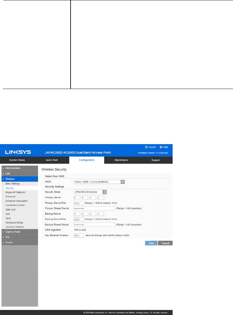
Key Renewal
Timeout
Specify the value of Group Key Renewal. It is a value
from 600 to 36000, and default is 3600.
WPA automatically changes secret keys after a
certain period of time. The group key interval is the
period of time in between automatic changes of the
group key, which all devices on the network share.
Constantly keying the group key protects your
network against intrusion, as the would-be intruder
must cope with an ever-changing secret key.
WPA/WPA2-Enterprise
WPA/WPA2-Enterprise requires a RADIUS Server on your LAN to provide the client
authentication. Data transmissions are encrypted using WPA/WPA2 standard.
41

WPA/WPA2-Enterprise
Primary Server Enter the IP address of the RADIUS Server on your
network.
Primary Server Port Enter the port number used for connections to the
RADIUS Server. It is a value from 1 to 65534, and
default is 1812.
Primary Shared
Secret
Enter the key value to match the RADIUS Server. It
consists of 1 to 64 characters.
Backup Server The Backup Authentication Server will be used when
the Primary Authentication Server is not available.
Backup Server Port Enter the port number used for connections to the
Backup RADIUS Server. It is a value from 1 to 65534,
and default is 1812.
Backup Shared
Secret
Enter the key value to match the Backup RADIUS
Server. It consists of 1 to 64 characters.
WPA Algorithm The encryption method is TKIP or AES.
Key Renewal
Timeout
Specify the value of Group Key Renewal. It is a value
from 600 to 36000, and default is 3600 second.
WPA automatically changes secret keys after a
certain period of time. The group key interval is the
period of time between automatic changes of the
group key, which all devices on the network share.
Constantly keying the group key protects your
network against intrusion, as the would-be intruder
must cope with an ever-changing secret key.
42

RADIUS
Use RADIUS server for authentication and dynamic WEP key generation for data encryption.
Authentication Server
Primary Server Enter the IP address of the RADIUS Server on your
network.
Primary Server Port Enter the port number used for connections to the
RADIUS Server. It is a value from 1 to 65534, and
default is 1812.
Primary Shared
Secret
Enter the key value to match the RADIUS Server. It
consists of 1 to 64 characters.
Backup Server The Backup Authentication Server will be used when
the Primary Authentication Server is not available.
Backup Server Port Enter the port number used for connections to the
Backup RADIUS Server. It is a value from 1 to 65534,
and default is 1812.
Backup Shared
Secret
Enter the key value to match the Backup RADIUS
Server. It consists of 1 to 64 characters.
43
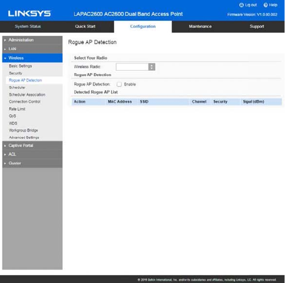
Rogue AP Detection
Go to Configuration > Wireless > Rogue AP Detection to detect the unexpected or unauthorized
access point installed in a secure network environment.
44

Radio
Wireless Radio Select the desired radio from the list.
Radio 1 is for 2.4GHz, and Radio 2 is for 5GHz.
Rogue AP Enable or disable Rogue AP Detection on the selected radio.
Note—Scanning happens when rouge AP is enabled or you
can click Refresh to trigger scanning again.
Detected Rogue AP List
Action Click Trust to move the AP to the Trusted AP List.
MAC Address The MAC address of the Rogue AP.
SSID The SSID of the Rogue AP.
Channel The channel of the Rogue AP.
Security The security method of the Rogue AP.
Signal The signal level of the Rogue AP.
Trusted AP List
Action Click Untrust to move the AP to the Rogue AP List.
MAC Address The MAC address of the Trusted AP.
SSID The SSID of the Trusted AP.
Channel The channel of the Trusted AP.
Security The security method of the Trusted AP.
Signal The signal level of the Trusted AP.
New MAC
Address
Add one trusted AP by MAC address.
45
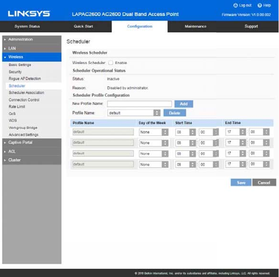
Scheduler
Go to Configuration > Wireless > Scheduler to configure a rule with a specific time interval for
SSIDs to be operational. Automate enabling or disabling SSIDs based on the profile definition.
Support up to 16 profiles and each profile can include four time rules.
46

Scheduler
Wireless
Scheduler
Enable or disable wireless scheduler on the radio. It is
disabled by default.
If disabled, even if some SSIDs are associated with
profiles, they will be always active.
Scheduler Operational Status
Status The operational status of the scheduler.
Reason The detailed reason for the scheduler operational status.
It includes the following situations.
xSystem time is outdated.
Scheduler is inactive because system time is
outdated.
xAdministrative Mode is disabled.
Scheduler is disabled by administrator.
xActive
Scheduler is active.
Scheduler Profile configuration
New Profile Name Enter the name for new profile.
Profile Name Select the desired profile from the list to configure.
Day of the Week Select the desired day from the list.
Option None means this time rule is disabled.
Start Time Choose the start time.
Finish Time Choose the finish time.
47
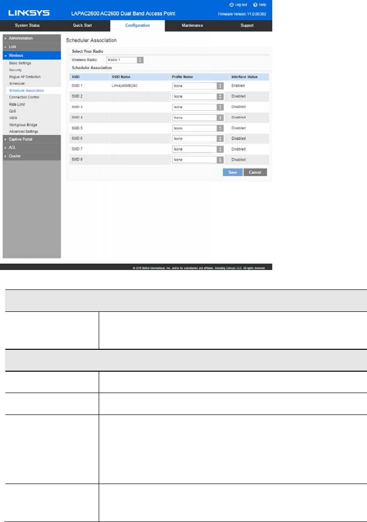
Scheduler Association
Go to Configuration > Wireless > Scheduler Association to associate defined scheduler profiles
with SSIDs.
Radio
Wireless Radio Select the desired radio from the list.
Radio 1 is for 2.4 GHz, and Radio 2 is for 5 GHz.
Scheduler Association
SSID The index of SSID.
SSID Name The name of the SSID.
Profile Name Choose the profile that is associated with the SSID.
If the profile associated with the SSID is deleted, then
the association will be removed.
Option None means no scheduler profile is associated.
Interface Status The status of the SSID. It can be Enabled or Disabled.
Scheduler only works when the SSID is enabled.
48
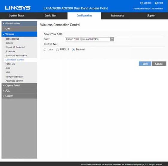
Connection Control
Go to Configuration > Wireless > Connection Control to define whether listed client stations may
authenticate with the access point.
49

SSID Select the desired SSID from the list.
Control Type Select the option from the drop-down list as desired.
xLocal: Choose either Allow only following MAC
addresses to connect to wireless network or
Prevent following MAC addresses from connection
to wireless network. You can enter up to 20 MAC
addresses of wireless stations or choose the MAC
address from Wireless Client List.
xRADIUS
Primary/Backup RADIUS Server - Enter the IP
address of the RADIUS Server.
Primary/Backup RADIUS Server Port– Enter the
Port
number of the RADIUS Server.
Primary/Backup Shared Secret - This is shared
between the wireless access point and the RADIUS
Server while
authenticating the device attempting to connect.
xDisabled
50
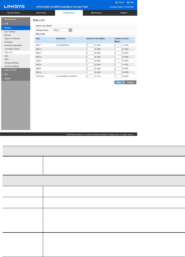
Rate Limit
Go to Configuration > Wireless > Rate Limit to limit downstream and upstream rate of SSIDs.
Radio
Wireless Radio Select the desired radio from the list.
Radio 1 is for 2.4GHz, and Radio 2 is for 5GHz.
Rate Limit
SSID The index of SSID.
SSID Name The name of the SSID.
Upstream
Rate
Enter a maximum upstream rate for the SSID. The range is
from 0 to 400 Mbps for Radio 1 and from 0 to 1000 Mbps
for Radio 2; 0 means no limitation.
Downstream
Rate
Enter a maximum downstream rate for the SSID. The range
is from 0 to 400 Mbps for Radio 1 and from 0 to 1000
Mbps for Radio 2; 0 means no limitation.
51
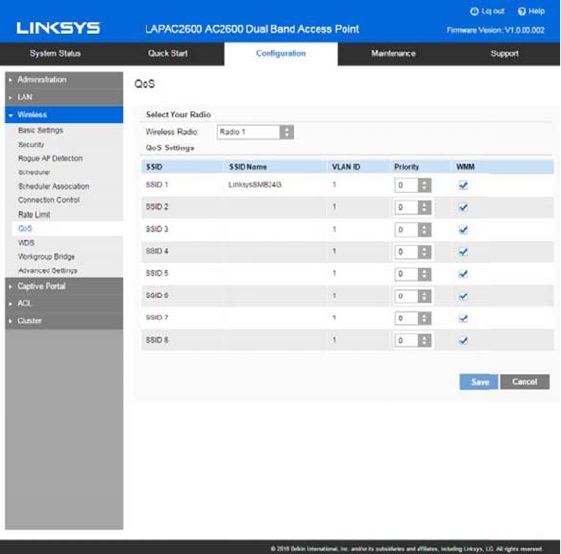
QoS
Go to Configuration > Wireless > QoS (Quality of Service) to specify priorities for different traffic
coming from your wireless client. Lower priority traffic will be slowed down to allow greater
throughput or less delay for high priority traffic.
52

QoS Setting
Wireless Radio Select the desired radio from the list.
Radio 1 is for 2.4GHz, and Radio 2 is for 5GHz.
QoS Settings
SSID The index of SSID.
SSID Name The name of the SSID.
VLAN ID The VLAN ID of the SSID.
Priority Select the priority level from the list. VLAN must be enabled
in order to set priority.
The 802.1p will be included in the VLAN header of the
packets which are received from the SSID and sent from
Ethernet or WDS interface.
WMM Enable or disable WMM.
WMM (Wi-Fi Multimedia) is a component of the IEEE
802.11e wireless LAN standard for QoS.
WMM provides prioritization of wireless data packets from
different applications based on four access categories:
voice, video, best effort, and background. For an application
to receive the benefits of WMM QoS, both it and the client
running that application have to have WMM enabled.
Legacy applications that do not support WMM and
applications that do not require QoS, are assigned to the
best effort category, which receives a lower priority than
voice and video.
WMM is enabled by default.
53
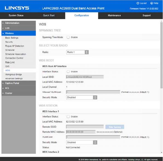
WDS
Go to Configuration > Wireless > WDS (Wireless Distribution System) to expand a wireless
network through multiple access points instead of linking them with a wired backbone.
WDS only works and interacts with LAPN300, LAPN600, LAPAC1200, LAPAC1750 or
LAPAC2600 devices.
The access point can act as WDS Root or WDS Station:
xWDS Root - Receives WDS connections from remote WDS Stations.
xWDS Station - Connects to remote WDS Root. Supports up to 4 WDS Stations on each
wireless radio.
54

Spanning Tree (recommended if you configure WDS connections)
Spanning Tree When enabled, STP helps prevent switching loops.
WDS Settings
Radio Select the desired radio from the list.
Radio 1 is for 2.4 GHz, and Radio 2 is for 5 GHz.
WDS Root
Interface
Status
Enable or Disable the WDS Root.
Be sure the following settings on WDS Root device are
determined and configured. The WDS Station must use the
same settings as Root afterwards.
xRadio
xIEEE 802.11 Mode
xChannel Bandwidth
xChannel
Note—It is highly recommended that static channel is
configured on both APs. Do not use Auto channel option
when you enable WDS, as both APs in a WDS link must be
on the same radio channel. If Auto option is configured,
there is chance two access points run on different channels
and WDS link cannot establish.
Workgroup Bridge and WDS will not work at the same time
on one wireless radio. When Workgroup Bridge is enabled,
WDS will be disabled automatically on the same radio.
Local SSID Enter name of the WDS Root SSID (used when connected
by WDS Stations).
Local MAC
Address
MAC address of the WDS Root SSID.
Local Channel The channel used by WDS Root SSID. WDS stations must
use same channel as the WDS Root.
Channel can be changed in Basic Settings page.
55

Allowed VLAN
List
Enter the list of VLANs accepted by the WDS Root.
When VLAN is enabled, WDS Root receives from WDS
Stations only packets in the VLAN list. Packets not in the
list will be dropped.
The VLAN list is only applicable when VLAN is enabled.
The VLAN list includes 1 to 16 VLAN IDs separated by ","
such as "100,200,300,400,500,600,700,800".
Security
Settings
Setting can be Disabled, WPA-Personal, WPA2-Personal,
WPA2-Enterprise or WPA/WPA2-Enterprise.
WDS Station
Interface
Status
Enable or disable the WDS Station.
Before configuring a WDS Station, be sure the following
settings of the device are identical to the WDS Root that
will be connected.
xRadio
xIEEE 802.11 Mode
xChannel Bandwidth
xChannel
Note—It is highly recommended that static channel is
configured on both APs. Do not use Auto channel option
when you enable WDS, as both APs in a WDS link must be
on the same radio channel. If Auto option is configured,
there is chance two access points run on different channels
and WDS link cannot establish.
Workgroup Bridge and WDS will not work at the same time
on one wireless radio. When Workgroup Bridge is enabled,
WDS will be disabled automatically on the same radio.
Remote SSID Enter the name of the Root’s SSID. Click Site Survey and
choose from the list. You must do this for WDS Station to
connect to a remote WDS Root.
56

Remote MAC
Address
MAC address of the access point on the other end of the
WDS link. Optional
WDS Station connects to remote WDS Root by matching
SSIDs. When there is more than one remote WDS Root with
the same SSID, the WDS Station can differentiate them by
MAC address.
The format is xx:xx:xx:xx:xx:xx.
VLAN List Enter the list of VLANs that are accepted by the WDS
Station.
When VLAN is enabled, the WDS Station forwards to the
remote WDS Root only packets in the VLAN list. Packets
not in the VLAN list cannot be forwarded to the remote
WDS Root.
The VLAN List is only applicable when VLAN is enabled.
The VLAN list includes 1 to 8 VLAN IDs separated by ","
such as "100,200,300,400,500,600,700,800".
Security Mode The type of encryption to use on the WDS link. It must be
unique to the access point on the other end of the WDS link.
The options are Disabled, WPA Personal, WPA2 Personal,
WPA Enterprise or WPA2 Enterprise.
Status Status of the WDS interface. It can be Disabled, Connected
or Not Connected.
57
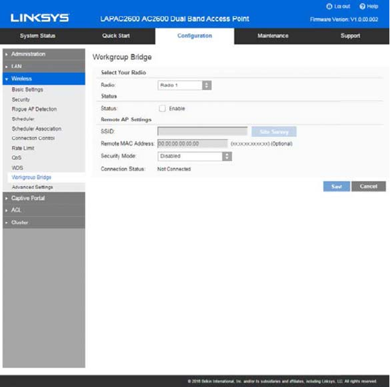
Workgroup Bridge
Go to Configuration > Wireless > Workgroup Bridge to extend the accessibility of a remote
network. In Workgroup Bridge mode, the access point acts as a wireless station (STA) on the
wireless LAN. It can bridge traffic between a remote wired network and a wireless LAN.
When Workgroup Bridge is enabled, SSID configuration still works to provide wireless services to
clients.
All access points participating in Workgroup Bridge must have the identical settings for Radio
interface, IEEE 802.11 mode, Channel Bandwidth, Channel (Auto is not recommended).
58

Workgroup Bridge
Radio Select the desired radio from the list.
Radio 1 is for 2.4 GHz, and Radio 2 is for 5 GHz.
Workgroup Bridge Status
Status Enable or disable Workgroup Bridge function.
Before configuring Workgroup Bridge, make sure all devices
in Workgroup Bridge have the following identical settings.
xRadio
xIEEE 802.11 Mode
xChannel Bandwidth
xChannel
Note—It is highly recommended that static channel is
configured on both APs. Do not use the Auto channel option
when you enable Workgroup Bridge, as both APs in a
Workgroup Bridge link must be on the same radio channel. If
Auto option is configured, there is a chance two access
points will run on different channels which prevents
Workgroup Bridge link from being established.
Remote AP Settings
SSID Enter the name of the SSID to which Workgroup Bridge will
connect. Click Site Survey to choose from the list. You
must do this for Workgroup Bridge to connect to a remote
access point.
Remote MAC
Address
Normally, Workgroup Bridge connects to a remote access
point by matching SSID. When more than one remote
access point has the same SSID, Workgroup Bridge can
connect to different remote access points.
Optional: You can specify the MAC address of the remote
access point to limit Workgroup Bridge’s connection to a
specific remote access point.
The format is xx:xx:xx:xx:xx:xx.
59
Security Mode Select the desired mode from the list.
xDisabled
xWPA-Personal
xWPA2-Personal
xWPA-Enterprise
xWPA2-Enterprise
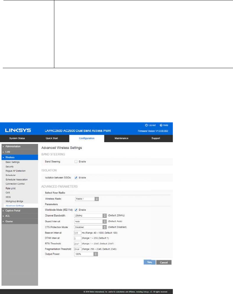
Advanced Settings
Go to Configuration >Wireless >Workgroup Bridge to configure advanced parameters of wireless
radios.
60

Band Steering
Band Steering Enable or disable Band Steering function.
Band Steering is a technology that detects whether
the wireless client is dual-band capable. If it is, band
steering pushes the client to connect to the less-
congested 5GHz network. It does this by actively
blocking the client’s attempts to connect with the
2.4GHz network.
Isolation
Isolation between
SSIDs
Define whether to isolate traffic between SSIDs. If
enabled, wireless clients in different SSIDs cannot
communicate with each other. Enabled by default.
Advanced Parameters
Wireless Radio Select the desired radio from the list.
Radio 1 is for 2.4GHz, and Radio 2 is for 5GHz.
Worldwide Mode
(802.11d)
Worldwide Mode (802.11d) enables the access point
to direct connected wireless devices to radio settings
specific to where in the world the devices are in use.
Channel Bandwidth Select the designed channel bandwidth for the
wireless radio.
20MHz - Select if you are not using any 802.11n
wireless devices.
20/40MHz - Select if you are using both 802.11n and
non-802.11n wireless devices.
20/40/80MHz - Select if you are using 802.11ac,
802.11n and non-802.11n wireless devices.
Guard Interval Select the guard interval manually for Wireless-N
connections. The two options are Short
(400nanoseconds) and Long (800nanoseconds). The
default is Auto.
61

CTS Protection
Mode
CTS (Clear-To-Send) Protection Mode boosts the
access point's ability to catch all Wireless-G
transmissions, but it severely decreases
performance. By default, CTS Protection Mode is
disabled, but the access point will automatically
enable this feature when Wireless-G devices are not
able to transmit to the access point in an environment
with heavy 802.11b traffic.
Beacon Interval The access point transmits beacon frames at regular
intervals to announce the existence of the wireless
network. Enter the interval between the
transmissions of beacon frames. The value range is
between 40 and 1000 milliseconds and default is
100 milliseconds.
DTIM Interval Enter the Delivery Traffic Information Map (DTIM)
period, an integer from 1 to 255 beacons. The default
is 1 beacon.
The DTIM message is an element included in some
beacon frames. It indicates which client stations,
currently sleeping in low-power mode, have data
buffered on the access point awaiting pickup.
The DTIM period that you specify indicates how often
the clients served by this WAP device should check
for buffered data still on the access point awaiting
pickup.
For example, if you enter 1, clients check for buffered
data on the access point at every beacon. If you enter
10, clients check on every 10th beacon.
62

RTS Threshold Enter the Request to Send (RTS) Threshold value, an
integer from 1 to 2347. The default is 2347 octets.
The RTS threshold indicates the number of octets in a
Medium Access Control Protocol Data Unit (MPDU)
below which an RTS/CTS handshake is not performed.
Changing the RTS threshold can help control traffic
flow through the access point, especially one with a
lot of clients. If you specify a low threshold value, RTS
packets are sent more frequently, which consumes
more bandwidth and reduces the throughput of the
packet. However, sending more RTS packets can help
the network recover from interference or collisions
that might occur on a busy network, or on a network
experiencing electromagnetic interference.
Fragmentation
Threshold
Enter the fragmentation threshold, an integer from
256 to 2346. The default is 2346.
The fragmentation threshold is a way of limiting the
size of packets (frames) transmitted over the
network. If a packet exceeds the fragmentation
threshold you set, the fragmentation function is
activated and the packet is sent as multiple 802.11
frames.
If the packet being transmitted is equal to or less than
the threshold, fragmentation is not used. Setting the
threshold to the largest value (2,346 bytes, which is
the default) effectively disables fragmentation.
Fragmentation involves more overhead because of
the extra work of dividing up and reassembling of
frames it requires, and because it increases message
traffic on the network. However, fragmentation can
help improve network performance and reliability if
properly configured.
Output Power Select the output power of the access point. If many
access points exist, lower power can reduce the
signal interference among them.
63
Captive Portal
Captive Portal is a method of securing access to the Internet from within a wireless network.
Users must enter authentication credentials before their wireless client devices can access the
Internet.
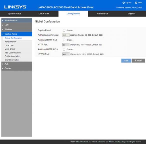
Global Configuration
Go to Configuration > Captive Portal > Global Configuration to change settings and modify
captive portal authentication access port number if needed.
64

Captive Portal Enable or Disable Captive Portal function globally.
Captive Portal is disabled by default.
Authentication
Timeout
The number of seconds the access point keeps an
authentication session open with a wireless client. If
the client fails to enter authentication credentials
within the timeout period, the client may need to
refresh the web authentication page.
The range is from 60 to 600 seconds. Default is 300.
Additional HTTP
Port
HTTP portal authentication uses the HTTP
management port by default. You can configure an
additional port for that process.
HTTP Port Once Additional HTTP Port is enabled, define an
additional port for HTTP protocol. The value can be
80 or 1024 to 65535 and is 80 by default. The HTTP
Port must be different from the HTTP port in
Administration > Management Access
page.
Additional HTTPS
Port
HTTPS portal authentication uses the HTTPS
management port by default. You can configure an
additional port for that process.
HTTPS Port Once Additional HTTPS Port is enabled, define an
additional port for HTTPS protocol. The value can be
443 or 1024 to 65535 and is 443 by default. The
additional HTTPS Port must be different from the
HTTPS port in
Administration > Management Access
page.
65
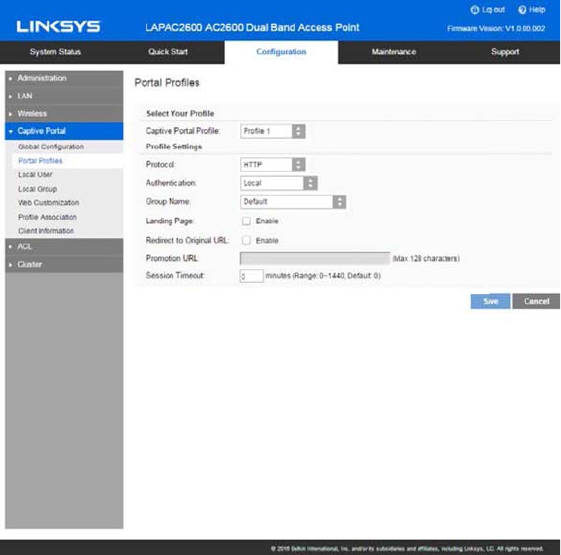
Portal Profiles
Go to Configuration > Captive Portal > Portal Profiles to define detailed settings for Captive
Portal profile. Create up to two profiles.
66

Portal Profiles
Captive Portal
Profile
Select a profile to configure.
Protocol Select the protocol used to access the Portal
Authentication web server. It can be HTTP or HTTPS.
Authentication Select an authentication method for clients.
Local - The access point uses a local database to
authenticated wireless clients.
Radius - The access point uses a database on a
remote RADIUS server to authenticate wireless
clients. The RADIUS server must support EAP-MD5.
Password Only - Wireless clients only need a
password. Username is unnecessary.
No Password - Wireless clients accept defined terms
to access the wireless network. Password and
username both are unnecessary.
Landing Page Enable Landing Page to determine where
authenticated wireless clients will be directed after
logging in at Captive Portal. Choose
Original URL
or
Promotion URL
.
Redirect to Original
URL
If Landing Page is enabled, this setting redirects
authenticated wireless clients from the Captive
Portal login screen to the URL the user typed in.
Promotion URL Enter a URL to which authenticated clients will be
redirected from the Captive Portal login page.
Landing Page must be enabled and Redirect to
Original URL must be disabled.
Session Timeout Set the session time in minutes. The access point will
disconnect authenticated clients when the session
time expires. Session time can range from 0 to 1440
minutes. The default is 0 minutes, which means no
timeout.
Local Authentication
Group Name Assigns an existing group to the profile. All users who
belong to the group are permitted to access the
network through this portal. The option 'Default'
means a group which includes all users.
67

Radius Authentication
Primary Server Enter the IP address of the RADIUS Server on your
network.
Primary Server Port Enter the port number used for connections to the
RADIUS Server.
Primary Shared
Secret
Enter the key value to match the RADIUS Server.
Backup Server The Backup Authentication Server will be used when
the Primary Authentication Server is not available.
Backup Server Port Enter the port number used for connections to the
Backup RADIUS Server.
Backup Shared
Secret
Enter the key value to match the Backup RADIUS
Server.
Password Only Authentication
Password The password for the profile. Wireless clients only
need one password to access the wireless network.
68
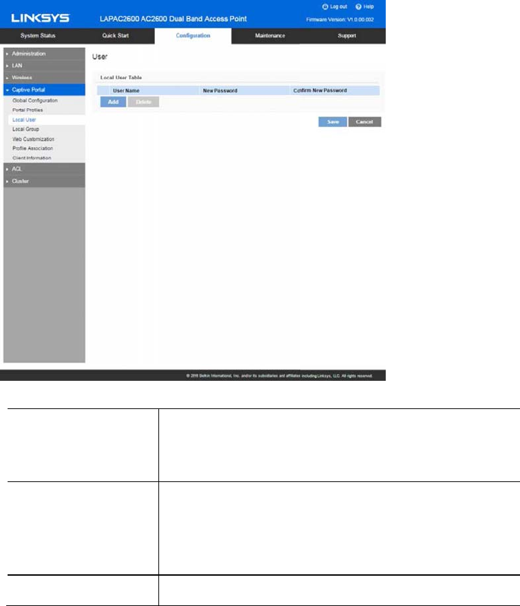
Local User
Go to Configuration > Captive Portal > Local User to configure user settings for Captive Portal.
Up to 128 users are supported.
User Name Enter the name of the user account.
The user name includes 1 to 32 characters. Special
characters except ':' and ';' are allowed.
Password Enter the password of the user account.
The password must be between 4 and 32 characters
in length. Special characters except ':' and ';' are
allowed.
Confirm Password Re-enter the password to confirm it.
69
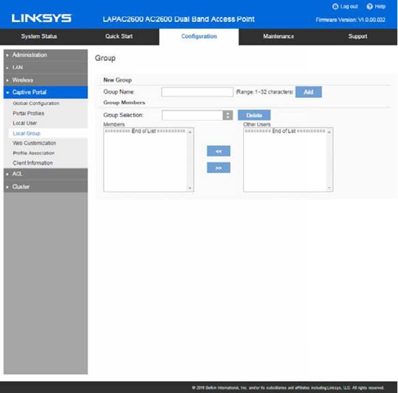
Local Group
Go to Configuration > Captive Portal > Local Group to configure group settings. Groups include
multiple local users and are mapped to Captive Portal profiles. Up to two groups are supported.
70
Group Name Enter the name of the new group.
The group name includes 1 to 32 characters. Special
characters except ':' and ';' are allowed.
Click Add.
Group Selection Select one group to delete or configure its user
members.
Members User members of the selected group. You can select
one user and click ">>" button to remove it.
Other Users Other users which don't belong to the selected group.
You can select one user and click "<<" button to add it
into the group.
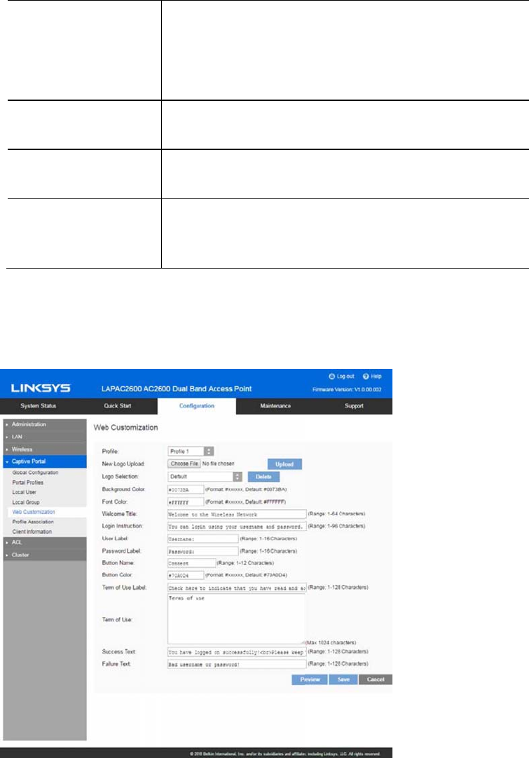
Web Customization
Go to Configuration > Captive Portal > Web Customization to customize the authentication web
page of Captive Portal.
71

Profile Select a profile to configure.
New Logo Upload Logos display in the web page. Select an image file
from your local PC and click Upload.
Formats .gif, .png and .jpg are supported. File size
cannot exceed 5KB.
One profile can support one default and one new logo
image. If a second new logo is uploaded, it will replace
the first new logo.
Logo Selection Select a logo image from the list.
Background Color The HTML code for the background color in 6-digit
hexadecimal format. The default is #0073BA.
Font Color The HTML code for the font color in 6-digit
hexadecimal format. The default is #FFFFFF.
Welcome Title Customize text to go with your logo. The default is
Welcome to the Wireless Network.
Login Instruction Customize text to go with the login box. Default text
for different authentication options:
Local Authentication/Radius Authentication
You can login using your username and password.
Password Only Authentication
You can login using your password.
Local Authentication
Click Connect to login.
User Label Customize the username text box. Enter up to 16
characters. The default is Username.
Password Label Customize the user password text box. Enter up to
16 characters. The default is Password.
Button Name Customize the text that appears in the log in button.
Enter up to 12 characters. The default is Connect.
Button Color The HTML code for the background color of the
button in 6-digit hexadecimal format. The default is
#70A0D4.
Terms of Use Label Customize the text to go with the checkbox. Enter up
to 128 characters. The default is Check here to
indicate that you have read and accepted the
following Terms of Use.
72
Terms of Use Customize the text to go with Terms of Use. Enter up
to 1024 characters. The default is Terms of Use.
Success Text Customize the text that shows when the client has
been authenticated. The default is You have logged
on successfully! Please keep this window open when
using the wireless network.
Failure Text Customize the text that shows when authentication
fails. Enter up to 128 characters. The default is Bad
username or password.
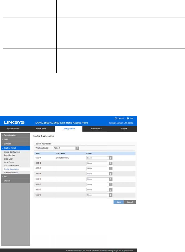
Profile Association
Go to Configuration > Captive Portal > Profile Association to associate defined Captive Portal
profiles with SSIDs.
73
SSID A list of available SSIDs.
SSID Name The name of the SSID.
Profile Name Choose the profile that is associated with the SSID.
If the profile associated with the SSID is deleted, then
the association will be removed.
If
None
is selected, it means no profile is associated.
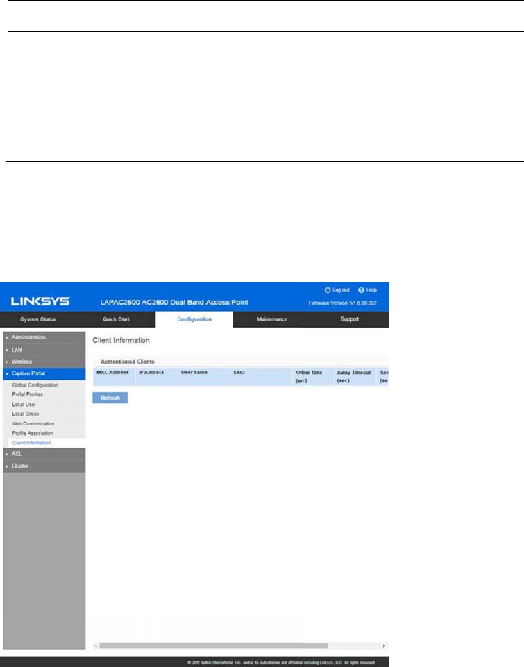
Client Information
Go to Configuration > Captive Portal > Client Information to view the status of wireless clients
that are authenticated by Captive Portal.
74

MAC Address MAC address of the client.
IP Address IP address of the client.
User Name User name used by the client to log in.
SSID Name Name of the SSID to which the client is connected.
Online Time How long the client has been online. Measured in
seconds.
Away Timeout An authenticated client that has been disconnected
from the access point has a specific amount of time
within which it may reconnect without re-
authentication. The timer starts when the client
disconnects from the SSID. After the time reaches
zero, the client is de-authenticated. If the timeout is
set to 0, the client is not de-authenticated. Measured
in seconds.
Session Timeout The remaining time of the authenticated session. The
timer starts when the client is authenticated. After
the time reaches zero, the client is de-authenticated.
If the value is fixed to 0, the session won't time out.
Measured in seconds.
75
ACL
ACLs are a collection of permit and deny conditions that can block unwarranted attempts to
reach network resources.
Each ACL is a set of up to 10 rules. Each rule specifies whether the contents of a given field
should be used to permit or deny access to the network. Rule can be based on various criteria and
may apply to one or more fields with a packet. The priority of each rule will be determined by the
rule index. Rule index number 1 has the highest priority to process and rule index number 10 is
the last one to process. There is an implicit deny for traffic that does not match any rules.
Once ACL has been created and configured, bind your ACL to the wireless interface. The ACL can
be applied to the traffic sent from a wireless client to the access point (upstream) or from the
access point to a wireless client (downstream).
To create ACLs and associate them to an interface, perform the following steps.
1. Create ACLs.
To add a new ACL, type in a name and choose IPv4 or IPv6. Click Add ACL. To add a rule to a
specific ACL, select the ACL name from the ACL Names dropdown list, and select a priority
from the Rule Index dropdown list. After that, you can define what kind of traffic to permit or
deny. Always remember there is an implicit deny for traffic that does not match any rules.
2. Associate the ACL with wireless interfaces by using ACL Association page.
To modify ACLs not in use, you have the following options.
1. You can unbind the ACL from a specific wireless interface by selecting None on the ACL
Association page.
2. If you don’t need an ACL anymore, you can delete it. To delete an ACL, select it from the
ACL Name dropdown list and click Delete ACL.
3. If you like to delete a rule associated with an ACL, click Reset next to Rule Index. That rule
will go back to default mode, all matching criteria for this specified rule will be gone.
76
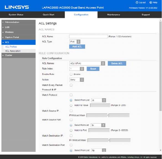
ACL Profiles
Go to Configuration > ACL > ACL Profiles to configure ACL profiles and their rules.
77

ACL Profile
ACL Name A name can include from 1 to 32 alphanumeric
characters to identify an ACL.
ACL Type Configuration type of ACL is IPv4 or IPv6. Click Add
ACL to add one new ACL profile.
Rule Configuration
ACL Names Select a profile to configure. An ACL profile includes
ACL name and type. Click Delete ACL to delete an
ACL.
Rule Index Select and configure a new rule for the selected ACL.
Enable Rule Enable or disable the ACL rule. It's disabled by
default.
Action Whether the ACL rule permits or denies an action.
Match Every Packet Rule matches the frame or packet regardless of its
contents.
If this is checked, you cannot configure any other
matching condition listed below; e.g, Protocol, Source
IP/Port, Destination IP/Port.
Match Protocol Use a Layer 3 or Layer 4 protocol as a matching
condition. Set the protocol value with following
methods.
ySelect From List
IP – Internet Protocol
ICMP – Internet Control Message Protocol
IGMP – Internet Group Management Protocol
TCP – Transmission Control Protocol
UDP – User Datagram Protocol
yMatch to Value
Set a protocol with protocol ID from 0 to 255.
78

Match Source IP Permit or deny packet by source IP address.
yIf the ACL type is IPv4, set an IPv4 address
and its wildcard mask.
Note—Wildcard 0 means to match that value, 1
means don’t match. For example, a mask of 0000
0000 0000 0000 0000 0000 1111 1111 which
means that you match on the bits where there is 0
and don't match on the bits where there are 1s. You
need to translate the 1s to a decimal integer and you
write 0 for each four zeros. In this example since
1111 1111 equals to 255, the wildcard mask would
be written as 0.0.0.255. To match traffic by source
IP address from 192.168.2.0 to 192.168.2.254,
enter the source IP as 192.168.2.0 and wildcard
mask as 0.0.0.255. To match a specific source IP
address e.g. 192.168.2.100, enter the source IP as
192.168.2.100 and wildcard mask as 0.0.0.0.
yIf the ACL type is IPv6, set an IPv6 address
and its prefix length. The range for IPv6 prefix
length is 0 to 128.
Match Source Port Permit or deny packet by a source port identified in
the datagram header.
ySelect from List
FTP – Port 21
FTP Data – Port 20
HTTP – Port 80
SMTP – Port 25
SNMP – Port 161
Telnet – Port 23
TFTP – Port 69
yMatch to Port
Enter a single destination port number for matched
packets. The port range is 0-65535.
79

Match Destination
IP
Permit or deny packet by destination IP address.
yIf the type of ACLs is IPv4, set an IPv4
address and its wildcard mask.
Note—Wildcard 0 means to match that value, 1
means don’t match. For example, a mask of 0000
0000 0000 0000 0000 0000 1111 1111 which
means that you match on the bits where there is 0
and don't match on the bits where there are 1s. You
need to translate the 1s to a decimal integer and you
write 0 for each four zeros. In this example since
1111 1111 equals to 255, the wildcard mask would
be written as 0.0.0.255. To match traffic by
destination IP address from 192.168.2.0 to
192.168.2.254, enter destination IP as 192.168.2.0
and wildcard mask as 0.0.0.255. To match a specific
destination IP address e.g. 192.168.2.100, enter the
destination IP as 192.168.2.100 and wildcard mask
as 0.0.0.0.
yIf the type of ACLs is IPv6, set an IPv6
address and its prefix length as destination IP.
The range for IPv6 prefix length is 0 to 128.
Match Destination
Port
Permit or deny packet by a destination port identified
in the datagram header.
ySelect from List
Choose a port by port name.
FTP – Port 21
FTP Data – Port 20
HTTP – Port 80
SMTP – Port 25
SNMP – Port 161
Telnet – Port 23
TFTP – Port 69
yMatch to Port
Enter a single destination port number for matched
packets. The port range is 0-65535.
80

Match IP DSCP Matches packets based on IP DSCP value.
ySelect From List
Choose a DSCP value from the list.
default Match packets with default dscp (000000)
af11 Match packets with AF11 dscp (001010)
af12 Match packets with AF12 dscp (001100)
af13 Match packets with AF13 dscp (001110)
af21 Match packets with AF21 dscp (010010)
af22 Match packets with AF22 dscp (010100)
af23 Match packets with AF23 dscp (010110)
af31 Match packets with AF31 dscp (011010)
af32 Match packets with AF32 dscp (011100)
af33 Match packets with AF33 dscp (011110)
af41 Match packets with AF41 dscp (100010)
af42 Match packets with AF42 dscp (100100)
af43 Match packets with AF43 dscp (100110)
cs1 Match packets with CS1(precedence 1) dscp
(001000)
cs2 Match packets with CS2(precedence 2) dscp
(010000)
cs3 Match packets with CS3(precedence 3) dscp
(011000)
cs4 Match packets with CS4(precedence 4) dscp
(100000)
cs5 Match packets with CS5(precedence 5) dscp
(101000)
cs6 Match packets with CS6(precedence 6) dscp
(110000)
cs7 Match packets with CS7(precedence 7) dscp
(111000)
ef Match packets with EF dscp (101110)
yMatch to Value
A custom DSCP value from 0 to 63.
Match IP
Precedence
Matches packets based on their IP Precedence value
from 0 to 7. This is applicable only when the type of
ACLs is IPv4.
81
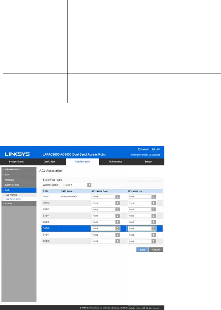
Match IP TOS Matches a type of service from the dropdown list.
This is applicable only when the type of ACLs is IPv4.
Normal Service – 0000
Minimize Monetary Cost – 0001
Maximize Reliability – 0010
Maximize Throughput – 0100
Minimize Delay - 1000
IPv6 Flow Label
A number that is unique to an IPv6 packet is used by
end stations to signify QoS handling in routers. The
range is 0 to 1048575.
ACL Association
Go to Configuration > ACL > ACL Association to associate defined ACL profiles with SSIDs.
82

ACL Association
SSID The index of SSID.
ACL Name Down Choose the profile that is associated with the SSID
for downstream (from access point to wireless client)
traffic.
If the profile associated with the SSID is deleted, the
association will be removed.
If None is selected, no profile is associated.
After switching the packet or frame to the outbound
interface, the ACL's rules are checked for a match.
The packet or frame is transmitted if it is permitted
and discarded if it is denied.
ACL Name Up Choose the profile that is associated with the SSID
for upstream (from wireless client to access point)
traffic.
If the profile associated with the SSID is deleted, the
association will be removed.
If None is selected, no profile is associated.
When a packet or frame is received by the access
point, the ACL's rules are checked for a match. The
packet or frame is processed if it is permitted and
discarded if it is denied.
Cluster
The cluster function provides a centralized method to administer and control wireless services
across multiple devices. When access points are clustered, you can view, deploy, configure, and
secure the wireless network as a single entity.
83
The access points within a cluster must have the same management VLAN configured. A cluster
can support 16 LAPAC2600access points as long as they are same model number.
In each cluster, one access point must be manually configured as the master access point. There
can only be one master in a cluster. This master will propagate configuration information, such as
wireless settings, time settings etc. to the other team members within a cluster. Login to the
master access point to change sharable parameter settings instead of slaves.
When firmware is upgraded on the master, all slaves within the same cluster will receive the
upgrade.
Clustered access points share these configurations:
xUser Accounts
xTime Settings
xLog Settings
xManagement Access
xDiscovery Settings
xIGMP/MLD Snooping
xWireless Network
Mode
xSSID Settings
xWireless Security
xRogue AP Detection
xWireless Scheduler
xWireless Scheduler
Association
xWireless Connection
Control
xRate Limit
xQoS
xAdvanced Wireless
Settings
xCaptive Portal
Settings
xEthernet Port
Settings
xVLAN Settings
xACL Settings
These configurations are not shared by clustered access points:
xIP Settings
xWDS
xOutput Power
xHostname
xWorkgroup Bridge
xWireless Channel
x802.1x Supplicant
84

Settings & Status
Go to
Configuration > Cluster > Settings & Status
to manage the AP cluster function.
Choose a member type.
Type Disabled—Disable the cluster function.
Master—Enable the cluster function and assign the
access point to be the master.
Note— If system detects there is one Master already
existed in the same cluster, the new access point that
likes to become master will be assigned to slave
automatically.
Slave—Enable the cluster function and assign the
access point to be the slave.
Note—When the cluster function is enabled, WDS and
workgroup bridge will be disabled automatically.
85
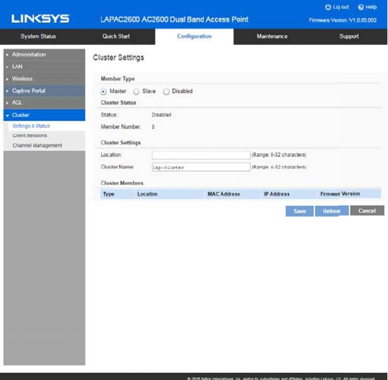
Master
86

Status Disabled—Cluster function is disabled.
Active—Cluster function is enabled and master is active.
Active (Backup Master)—Cluster function is enabled and backup master
is active.
Inactive (Cannot reach the master)—Cluster function is enabled but it's
inactive because device cannot reach the master.
Member Number Number of the active members in the cluster. If an access point joins the
cluster but is powered off or cannot reach the master, it is not counted.
Location (Optional) Where the access point is physically located; for example, Reception.
Length is from 0 to 32 bytes.
Cluster Name Name of the cluster for the LAP device to join; for example, “lab cluster”.
All access points with the same cluster name belong to the same
cluster. Length of this value is from 4 to 32 bytes and special
characters are allowed. This is a mandatory field if the cluster function
is turned on.
Backup Master When an access point works as a cluster slave, it can be enabled as a
backup master. When master gets offline, it will take the role of master.
When the backup master begins to work, it will send advertisements
and slaves will send keep-alive and report sessions to it. When
shareable settings are modified in it, it will share them to all slaves.
When master gets online again, this backup master AP will stop the
master function and let original master AP take over master role.
87
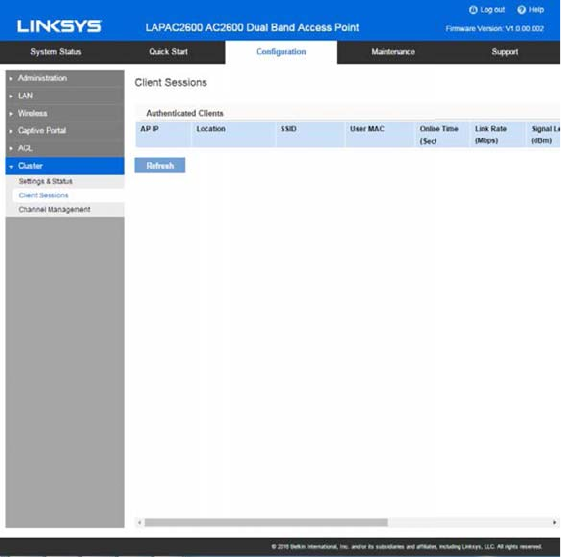
Client Sessions
Go to Configuration > Cluster > Client Sessions to see the status of wireless clients within the
cluster.
The session is the period of time in which a user on a client device (station) with a unique MAC
address maintains a connection with the wireless network. The session begins when the WLAN
client logs on to the network, and the session ends when the WLAN client either logs off
intentionally or loses the connection for some other reason.
When one wireless client of Captive Portal roams from one access point to another in the same
cluster, it need not re-authenticate.
88

IP Address IP address of the access point to which the client
connects.
Location Location of the access point to which the client
connects.
SSID SSID name of the access point to which the client
connects.
User MAC MAC address of the client.
Online Time Displays how long this client has been online since it is
authenticated. Unit is second.
Link Rate Indicates the link rate of the client. Unit is Mbps.
Signal The signal strength of the client is displayed. Unit is
dBm.
Rx Total The total bytes which are received from the client by
the access point. Unit is Byte.
Tx Total The total bytes which are sent to the client by the
access point. Unit is Byte.
Rx Rate Current transfer rate of the data which are received
from the client by the access point. Unit is Kbps.
Tx Rate Current transfer rate of the data which are sent to
the client by the access point. Unit is Kbps.
89
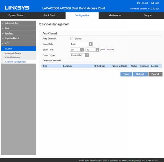
Channel Management
Go to Configuration > Cluster > Channel Management to manage the channel assignments for
access points within a cluster.
When channel management is enabled, the access point automatically assigns radio channels
within a cluster. Auto channel assignment reduces mutual interference (or interference with other
access points outside of its cluster) and maximizes Wi-Fi bandwidth to help maintain efficient
communication over the wireless network.
90

Auto Channel
Auto Channel Access point scans available Wi-Fi channels and
changes the channel if better network performance is
possible. Disabled by default.
Scan Day Choose the day of the week when Auto Channel scans
Wi-Fi channels. You may choose specific days or have
the access point scan and select the best channel
daily.
ScanTime Choose the time of day when Auto Channel performs
scan.
Scan Trigger Because Auto Channel will change the channel if it
finds a better one, you can choose when to allow a
scan.
xImmediately – Scan according to the day/time
specified.
yNo Clients – Scan only if no clients are
connected to the wireless radio. If there are
clients connected, the access point will
complete the Auto Channel operation the next
scheduled time when no clients are
connected.
Current Channels
Type Member type of the access point. It can be Master,
Slave or Backup Master.
Location Where the access point is physically located
IP Address IP address of the access point.
Wireless Radio 1 stands for 2.4Ghz radio, and 2 stands for 5Ghz
radio.
Status Status of the wireless radio. It can be Active or
Inactive.
Channel Current channel number of the wireless radio.
Locked Select if you feel the current channel is the best for
that radio.
91
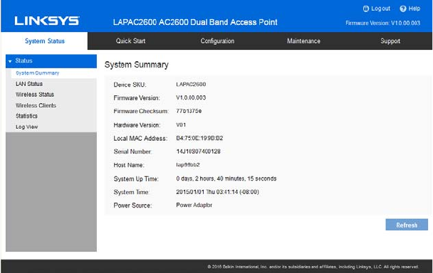
Chapter 4 - System Status
Status
System Summary
Go to System Status > Status > System Summary for status of the access point.
92

System Summary
Device SKU The SKU is often used to identify device model number
and region.
Firmware Version The version of the firmware currently installed.
Firmware
Checksum
The checksum of the firmware running in the access
point.
Hardware Version The version of the hardware.
Local MAC
Address
The MAC (physical) address of the wireless access
point.
Serial Number The serial number of the device.
Host Name The host name assigned to the access point.
System Up Time How long the system has been running since the last
restart or reboot.
System Time The current date and time.
Power Source The power source of the access point. It can be Power
over Ethernet (PoE) or Power Adapter. When two power
sources are plugged in, Power Adaptor will be
displayed.
LAG Status Indicates the status of LAG (Link Aggregation). It can
be "Inactive" or "Active"
xWhen LAG is inactive, only one Ethernet port
works at a given time.
xLAG only works when link speed and duplex of
the two Ethernet ports are the same and duplex
must be Full. LACP does not support half-
duplex.
xLAG is based on 802.3ad LACP (Link
Aggregation Control Protocol) so it works only
when link ends of the two Ethernet ports of the
Access Ports also support 802.3ad LACP and
enable it.
93

Buttons
Refresh Click to update the data on the screen.
94
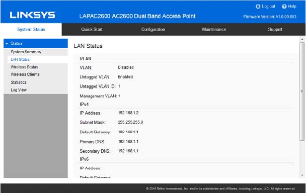
LAN Status
Go to System Status >Status >LAN Status to see settings and status of LAN interface.
95

VLAN
VLAN Enabled or disabled (default).
Untagged VLAN Enabled (default) or disabled.
When enabled, and if its VLAN ID is equal to Untagged
VLAN ID, all traffic is untagged when sent from LAN
ports. Untagged traffic can be accepted by LAN ports. If
disabled, traffic is always tagged when sent from LAN
port and only tagged traffic can be accepted from LAN
port.
By default, all traffic on the access point uses VLAN 1,
the default untagged VLAN. This means that all traffic is
untagged until you disable the untagged VLAN, change
the untagged traffic VLAN ID, or change the VLAN ID for
a SSID.
Untagged VLAN
ID
Displays the untagged VLAN ID. Traffic on the VLAN
that you specify in this field is not be tagged with a VLAN
ID when forwarded to the network. VLAN 1 is the default
ID for untagged VLAN and management VLAN.
Management
VLAN
Displays the Management VLAN ID. The VLAN
associated with the IP address you use to connect to the
access point. Provide a number between 1 and 4094 for
the Management VLAN ID. The default is 1.
This VLAN is also the default untagged VLAN. If you
already have a management VLAN configured on your
network with a different VLAN ID, you must change the
VLAN ID of the management VLAN on the access point.
96
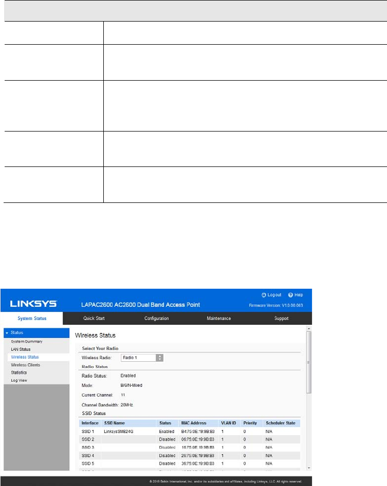
IPv4/v6
IP Address The IP address of the wireless access point.
Subnet Mask The Network Mask (Subnet Mask) for the IP address
above.
Default Gateway Enter the gateway for the LAN segment to which the
wireless access point is attached (the same value as the
PCs on that LAN segment).
Primary DNS The primary DNS address provided by the DHCP server
or configured manually.
Secondary DNS The secondary DNS address provided by the DHCP
server or configured manually.
Wireless Status
Go to System Status >Status >Wireless Status to see settings and status of wireless radios and
SSIDs.
97

Radio Status
Wireless Radio Select the desired radio from the list.
Radio 1 is for 2.4GHz, and Radio 2 is for 5GHz.
Radio Status Indicates whether the radio is enabled.
Mode Current 802.11 mode (a/b/g/n/ac) of the radio.
Channel The channel currently in use.
Channel
Bandwidth
Current channel bandwidth of the radio.
When set to 20 MHz, only the 20 MHz channel is in use.
When set to 20/40 MHz, Wireless-N connections will use
40 MHz channel, but Wireless-B and Wireless-G will still
use 20 MHz channel.
SSID Status
Interface SSID index.
SSID Name Name of the SSID.
Status Status of the SSID: Enabled or Disabled.
MAC Address MAC Address of the SSID.
VLAN ID VLAN ID of the SSID.
Priority The 802.1p priority of the SSID.
Scheduler
State
yN/A—No scheduler is enabled on the SSID, or the
SSID is disabled by administrator.
yActive—The SSID is enabled.
yInactive—The SSID is disabled.
98

WDS Root
Status Status of the WDS Root: Enabled or Disabled.
Local SSID Name of the WDS Root.
Local MAC MAC Address of the WDS Root.
VLAN List VLAN List of the WDS Root.
When VLAN function is enabled, WDS Root only receives
packets in the VLAN list from WDS Stations and packets
not in the list will be dropped.
WDS Station
Interface The index of WDS Station.
Status Status of the WDS Station: Enabled or Disabled.
Local MAC MAC Address of the WDS Root.
Remote SSID SSID of the destination access point which is on the other
end of the WDS link to which data is sent or handed-off
and from which data is received.
Remote MAC MAC Address of the destination access point which is on
the other end of the WDS link to which data is sent or
handed-off and from which data is received.
Connection
Status
Status of the WDS Station: Disabled, Connected or Not
Connected.
Workgroup Bridge Status
Status Status of the Workgroup Bridge: Enabled or Disabled.
Local MAC MAC address of the Workgroup Bridge.
Remote SSID SSID of the destination access point on the other end of
the Workgroup Bridge link to which data is sent and from
which data is received.
Remote MAC MAC address of the destination access point on the other
end of the Workgroup Bridge link to which data is sent and
from which data is received.
Connection
Status
Status of the Workgroup Bridge: Disabled, Connected or
Not Connected.
99
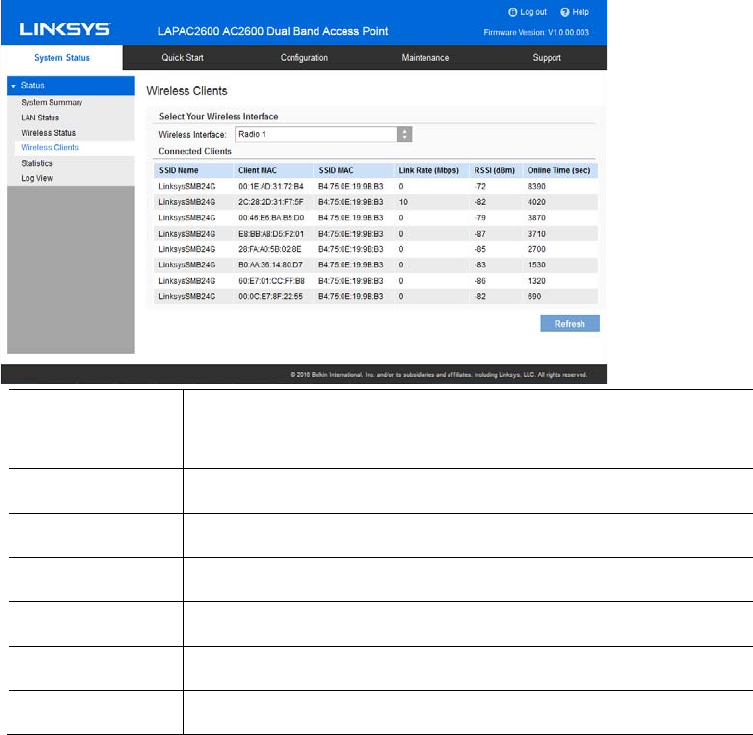
Wireless Clients
Go to System Status > Status > Wireless Clients to see connected clients based on each wireless
interface.
Wireless
Interface
Select the desired interface from the list. The interfaces
include eight SSIDs per radio.
SSID Name Name of the SSID to which the client connects.
Client MAC The MAC address of the client.
SSID MAC MAC of the SSID to which the client connects.
Link Rate The link rate of the client. Unit is Mbps.
RSSI The signal strength of the client. Unit is dBm.
Online Time How long this client has been online. Unit is seconds.
100
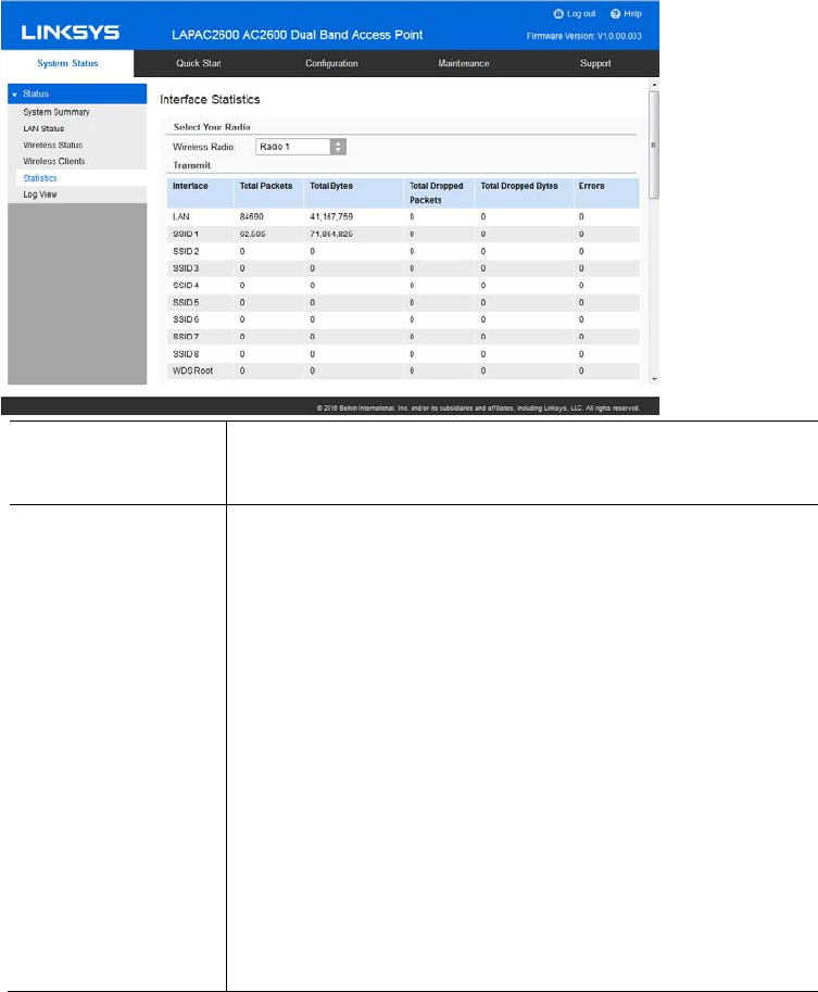
Statistics
Go to System Status > Status > Statistics to see real-time statistics on data transmitted and
received based on each SSID per Radio, and LAN interface.
Wireless Radio Select the desired radio from the list.
Radio 1 is for 2.4GHz, and Radio 2 is for 5GHz.
Transmit/Receive xTotal Packets—The total packets sent (in
Transmit table) or received (in Received table) by
the interface.
xTotal Bytes—The total bytes sent (in Transmit
table) or received (in Received table) by the
interface.
xTotal Dropped Packets—The total number of
dropped packets sent (in Transmit table) or
received (in Received table) by the interface.
xTotal Dropped Bytes—The total number of
dropped bytes sent (in Transmit table) or
received (in Received table) by the interface.
xErrors—The total number of errors related to
sending and receiving data on this interface.
101
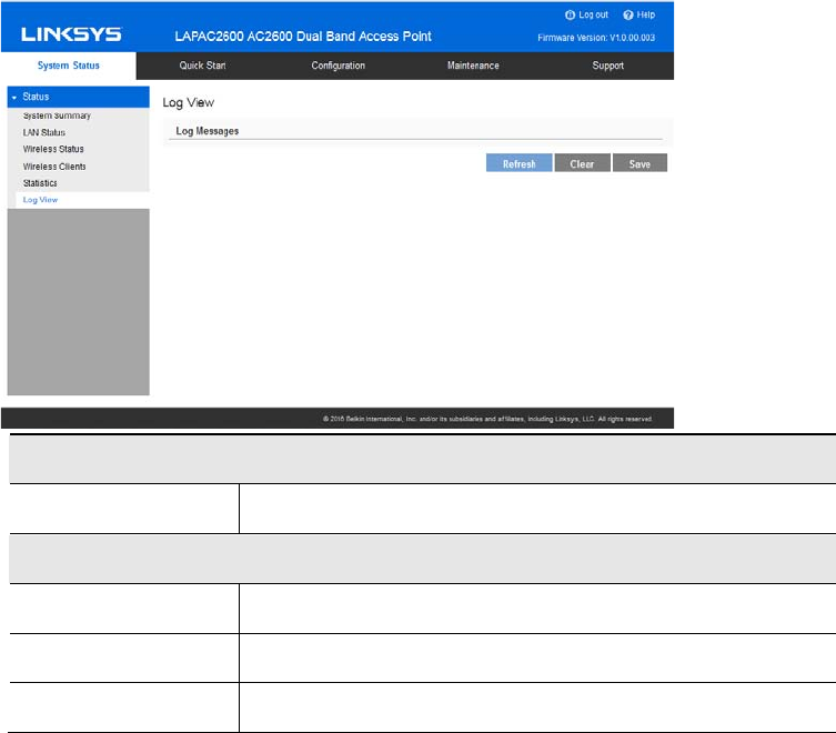
Log View
Go to System Status > Status > Log View to see a list of system events such as login attempts
and configuration changes.
Log Messages
Log Messages Show the log messages.
Buttons
Refresh Update the data on screen.
Save Save the log to a file on your PC.
Clear Delete the existing logs from device.
102
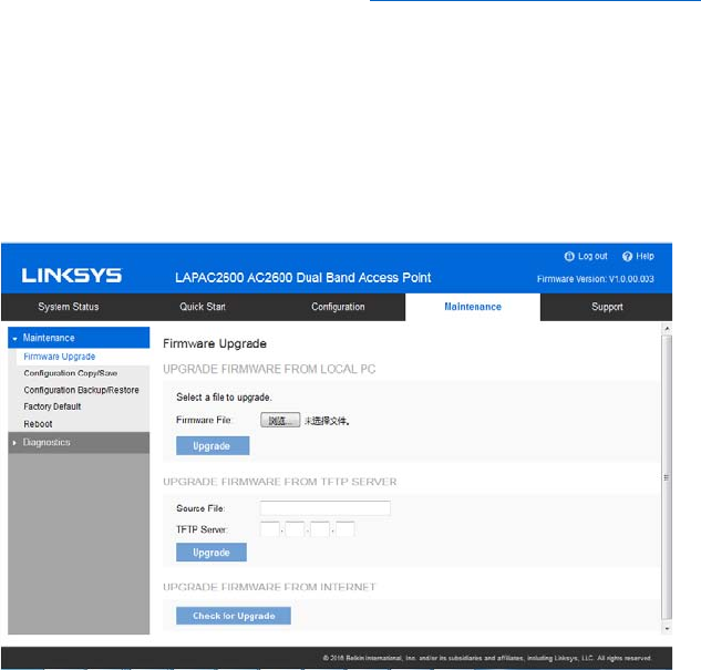
Chapter 5 --- Maintenance
Maintenance
Firmware Upgrade
Go to Maintenance > Maintenance > Firmware Upgrade to upgrade the firmware in the wireless
access point by using HTTP/HTTPS, or TFTP.
Check the Linksys support website (http://www.linksys.com/support) and download the latest
firmware release to a storage device or PC. Perform the firmware upgrade by following the steps
below.
If an access point works as master of an AP cluster, all slaves within the same cluster will be
updated, as well.
Do not power off the device or disconnect the Ethernet cable during the upgrade. The access
point will reboot automatically after the upgrade is complete.
To perform the firmware upgrade from local PC:
1. Click Choose File to navigate to the location of the upgrade file.
2. Select the upgrade file. Its name will appear next to the Choose File button.
3. Click Upgrade.
To perform the firmware upgrade from TFTP server:
1. Enter the IP address of the TFTP server and the source file. The source file is the firmware
filename you stored in your TFTP server. Only IPv4 addresses are supported.
2. Click Upgrade.
103
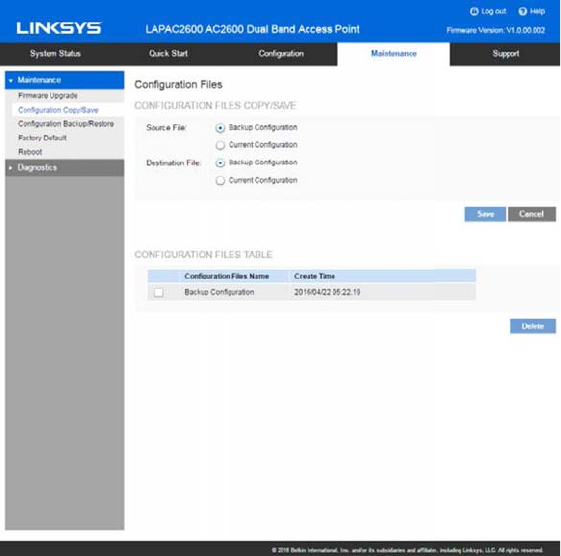
To perform a firmware upgrade from the Internet:
1. Click Check for Upgrade to see if there is new firmware available.
2. Click the OK on the popup dialogue box to start the firmware download and upgrade if a
new version of firmware is available.
Configuration Copy/Save
Go to Maintenance > Maintenance > Configuration Copy/Save to copy configurations within the
access point and delete copied configurations.
104

Configuration files copy/save
Configuration Files There are two kinds of configuration files in the access
point.
yBackup Configuration — An additional
configuration file saved in the flash memory
for use as a backup.
yCurrent Configuration — The configuration
which is running in the device currently. When
device boots up, device will read the settings
from this file.
Configuration Files
Copy/Save
Copy configuration file from one to another.
Source Configuration can be one of following:
yBackup Configuration (if it exists)
yCurrent Configuration
Destination Configuration can be one following:
yBackup Configuration
yCurrent Configuration
Need note that Source Configuration and Destination
Configuration cannot be same and if you copy Backup
Configuration to Current Configuration, device will
reboot after the copy.
Configuration Files Table
Configuration Files
Name
Configuration files which are copied in the access
point.
Create Time Creating time of configuration files in the access point.
105
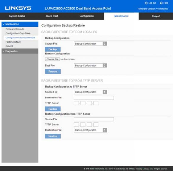
Configuration Backup/Restore
Go to Maintenance > Maintenance > Configuration Backup/Restore to download the
configuration file from the device. You can save it to external storage, e.g., your PC, or network
storage. You can also upload a previously saved configuration file from external storage to the
device. It is highly recommended you save one extra copy of the configuration file to external
storage after you are done with access point setup.
106

Backup/Restore to/from Local PC
Backup
Configuration
Once you have the access point working properly, you
should back up the settings to a file on your computer.
You can later restore the access point's settings from
this file, if necessary.
To create a backup file of the current settings:
xChoose a source file. It can be Backup
Configuration or Current Configuration.
xClick Backup.
xIf you don't have your browser set up to save
downloaded files automatically, locate where
you want to save the file, rename it if you like,
and click Save.
Restore
Configuration
To restore settings from a backup file:
1. Choose a destination file. It can be Backup
Configuration or Current Configuration.
2. Click Choose File.
3. Locate and select the previously saved backup
file.
4. Click Restore.
Backup/Restore to/from TFTP server
Backup
Configuration
To create a backup file of the current settings:
1. Choose a source file. It can be Backup
Configuration or Current Configuration.
2. Enter the destination file name you plan to save
in TFTP server.
3. Enter the IP address for the TFTP server. Only
IPv4 addresses are supported.
4. Click Backup.
107
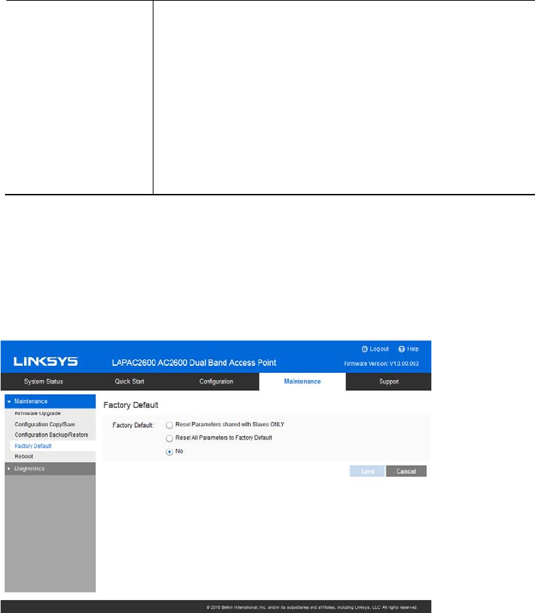
Restore
Configuration
To restore settings from a backup file:
1. Choose a destination file and it can be Backup
Configuration or Current Configuration.
2. Enter the source file name stored in TFTP
server.
3. Enter the IP address for the TFTP server. Only
IPv4 addresses are supported.
4. Click Restore.
Factory Default
It’s highly recommended you save your current configuration file before you restore to factory
default settings. To save your current configuration file, click Maintenance > Configuration
Backup/Restore.
108
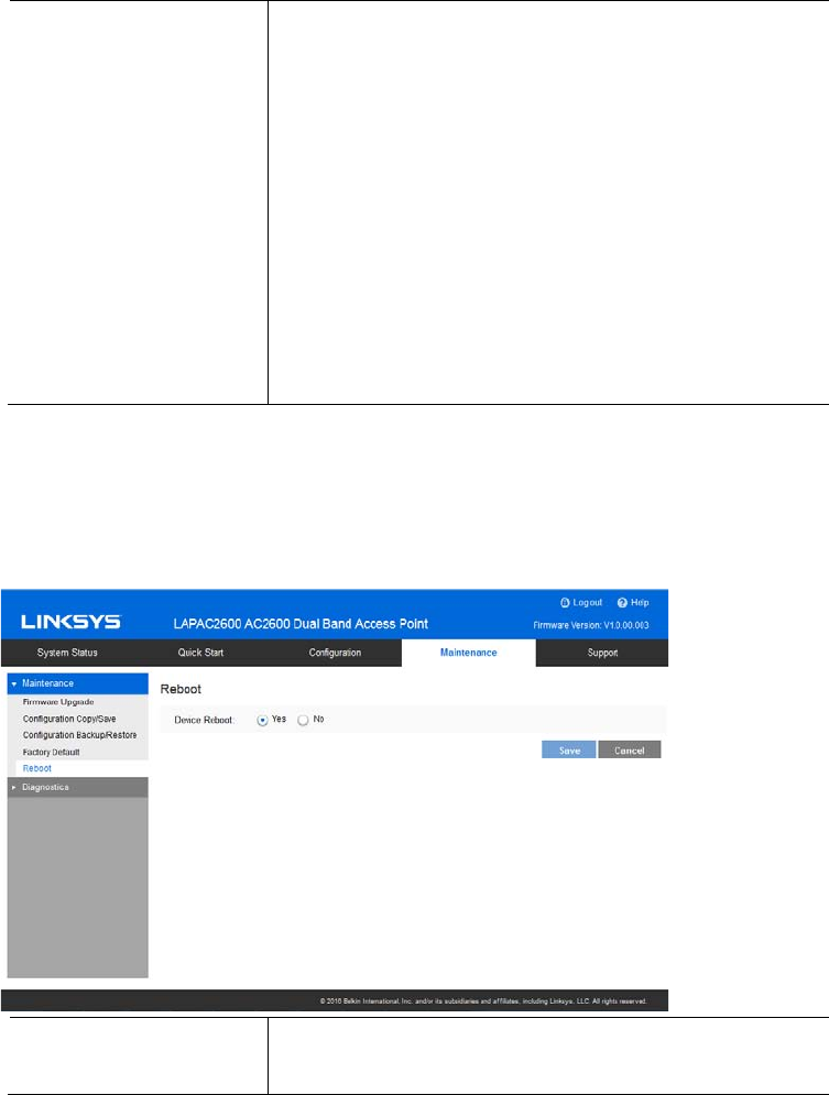
Factory Default To restore your access point to its factory defaults,
select an option and click Save.
xReset Parameters shared with Slaves ONLY
When current AP is a master of a cluster,
select this option to restore all sharable
parameters of current AP and its slaves to
factory defaults. Cluster settings and non-
sharable parameters will not reset.
xReset All Parameters to Factory Default
xNo
Don’t restore to factory defaults.
Reboot
Go to Maintenance > Maintenance > Reboot to power cycle the device. The current configuration
file will remain after reboot.
Device Reboot If you click Save when the Yes radio button is
selected, the device will power cycle.
109
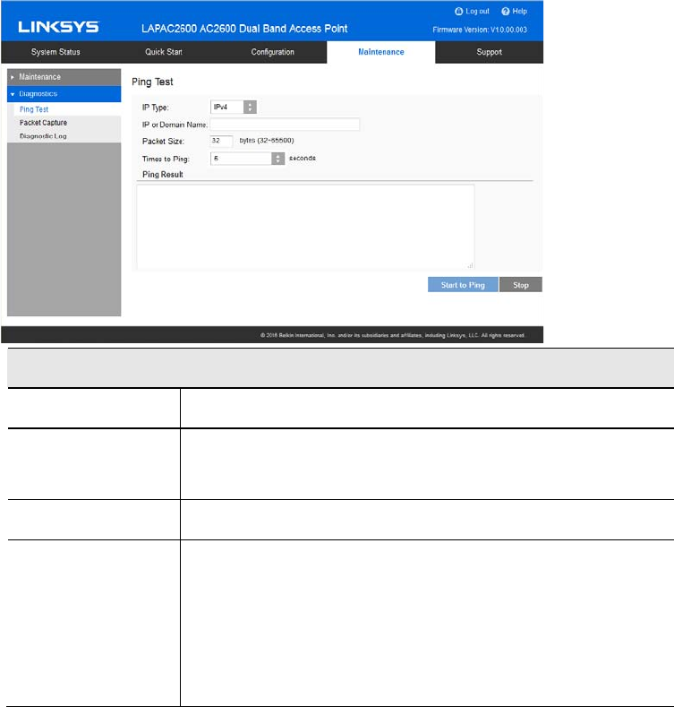
Diagnostics
Ping Test
Go to Maintenance > Diagnostics > Ping Test to determine the accessibility of a host on the
network.
General
IP Type Enter the IP type of destination address.
IP or URL
Address
Enter the IP address or domain name that you want to
ping.
Packet Size Enter the size of the packet.
Times to Ping Select the desired number from the drop-list.
x5
x10
x15
xUnlimited
110
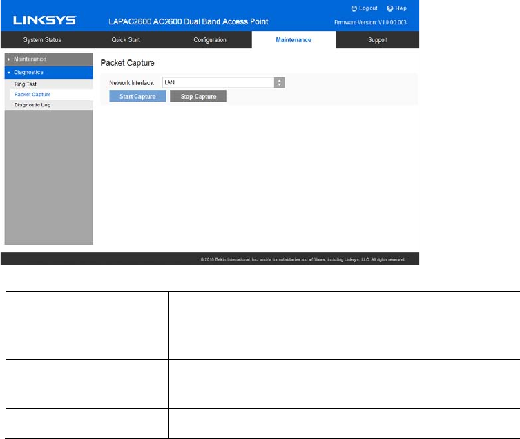
Packet Capture
Go to Maintenance > Diagnostics > Packet Capture to capture and store 802.3 packets received
and transmitted by the access point based on one specified network interface. The network
interface can be radio, SSID or LAN.
Network Interface Select the desired network interface from the drop-
down list. The interface can be Radio, SSID or
Ethernet.
Start Capture Click to start the capture. You will be asked to
specify a local file to store the packets.
Stop Capture Click to stop the capture.
111
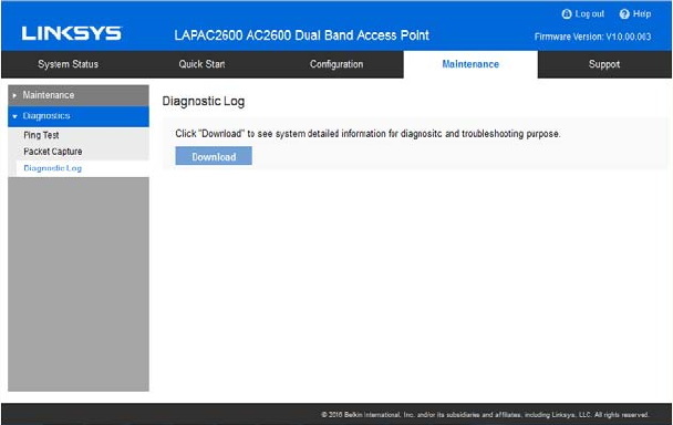
Diagnostic Log
Go to Go to Maintenance > Diagnostics > Diagnostic Log to get system detail information, such
as configuration file, system status and statistics data, hardware information, operational status.
The information is useful in troubleshooting and working with technical support.
Click Download to download the device diagnostic log into a local file.
112
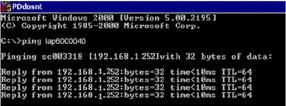
Appendix A - Troubleshooting
Overview
This chapter covers some common problems encountered while using the wireless access point,
and some possible solutions to them. If you follow the suggested steps and the wireless access
point still does not function properly, contact your dealer for further advice.
General Problems
I can't find new access point on my network.
Check the following:
xThe wireless access point is properly installed, LAN connections are OK, and it is powered
ON. Check the LEDs for system and port status.
xEnsure that your PC and the wireless access point are on the same network segment. (If
you don't have a router, this must be the case.)
xYou can use the following method to determine the IP address of the wireless access
point, and then try to connect using the IP address, instead of the name.
To find the access point's IP address:
1. Open a MS-DOS Prompt or Command Prompt Window.
2. Use the Ping command to ping the wireless access point. Enter “ping” followed by the
default name of the wireless access point. Default name is “lap” followed by the last five
characters of device MAC address (e.g., ping lap964d6).
3. Check the output of the ping command to determine the IP address of the wireless access
point, as shown below.
If your PC uses a fixed (static) IP address, ensure that it is using an IP address that is in the
network segment (subnet) with the wireless access point. On Windows PCs, you can use Control
Panel >Network to check the properties for the TCP/IP protocol.
113

If there is no DHCP Server found, the wireless access point will roll back to an IP address and
mask of 192.168.1.252 and 255.255.255.0.
My PC can't connect to the LAN via the wireless access point.
Check the following:
xThe SSID and security settings on the PC match the settings on the access point.
xOn the PC, the wireless mode is set to Infrastructure.
xIf using the Access Control feature, the PC's name and address is in the Trusted Stations
list.
xIf using 802.1x mode, ensure the PC's 802.1x software is configured correctly. See
Appendix C(p. 122) for details of setup for the Windows XP 802.1x client. If using a
different client, refer to the vendor's documentation.
114
Appendix B - About Wireless LANs
Overview
Wireless networks have their own terms and jargon. You must understand many of these terms in
order to configure and operate a wireless LAN.
Wireless LAN Terminology
Modes
Wireless LANs can work in either of two (2) modes:
xAd-hoc
xInfrastructure
Ad-hoc Mode
Ad-hoc Mode does not require an access point or a wired (Ethernet) LAN. Wireless stations, e.g.,
notebook PCs with wireless cards, communicate directly with each other.
Infrastructure Mode
In Infrastructure Mode, one or more access points are used to connect wireless stations, e.g.,
notebook PCs with wireless cards, to a wired (Ethernet) LAN. The wireless stations can then
access all LAN resources.
Note—Access points can only function in Infrastructure Mode, and can communicate only with
wireless stations that are set to Infrastructure Mode.
SSID/ESSID
BSS/SSID
A group of wireless stations and a single access point, all using the same ID (SSID), form a Basic
Service Set (BSS).
Using the same SSID is essential. Devices with different SSIDs are unable to communicate with
each other.
115
ESS/ESSID
A group of wireless stations, and multiple access points all using the same ID (ESSID), form an
Extended Service Set (ESS).
Different access points within an ESS can use different channels. To reduce interference, it is
recommended that adjacent access points use different channels.
As wireless stations are physically moved through the area covered by an ESS, they will
automatically change to the access point that has the least interference or best performance.
Channels
xThe wireless channel sets the radio frequency used for communication.
xAccess points use a fixed channel. You can select the channel used. This allows you to
choose a channel that provides the least interference and best performance. For USA and
Canada, the following channels are available:
-2.4GHz:
yto 2.462 GHz; 11 channels
-5GHz:
y5.180 to 5.240 GHz; 4 channels
y5.745 to 5.825 GHz; 5 channels
xWhen using multiple access points it is better if adjacent access points use different
channels to reduce interference. The recommended channel spacing between adjacent
access points is five channels, e.g., use Channels 1 and 6, or 6 and 11.
xIn Infrastructure Mode wireless stations normally scan all channels looking for an access
point. If more than one access point can be used, the one with the strongest signal is used.
(This can only happen within an ESS.)
xIf using Ad-hoc Mode (no access point) all wireless stations should be set to use the same
channel. However, most wireless stations will still scan all channels to see if there is an
existing Ad-hoc group they can join.
WEP
WEP (Wired Equivalent Privacy) is a standard for encrypting data before it is transmitted. This is
desirable because it is impossible to prevent snoopers from receiving any data which is
transmitted by your wireless stations. If the data is encrypted, it is meaningless unless the
receiver can decrypt it.
If WEP is used, the wireless stations and the wireless access point must have the same settings.
116
WPA-PSK
In WPA-PSK, like WEP, data is encrypted before transmission. WPA is more secure than WEP. The
PSK (pre-shared key) must be entered on each wireless station. The 256-bit encryption key is
derived from the PSK, and changes frequently.
WPA2-PSK
This is a further development of WPA-PSK, and offers even greater security, using the AES
(Advanced Encryption Standard) method of encryption. It should be used if possible.
WPA-Enterprise
This version of WPA requires a RADIUS server on your LAN to provide the client authentication
according to the 802.1X standard. Data transmissions are encrypted using the WPA standard.
If this option is used:
xThe access point must have a client login on the RADIUS server.
xEach user must have a user login on the RADIUS server.
xEach user's wireless client must support 802.1X and provide the login data when
required.
All data transmission is encrypted using the WPA standard. Keys are automatically generated, so
no key input is required.
WPA2-Enterprise
This version of WPA2 requires a RADIUS server on your LAN to provide the clientauthentication
according to the 802.1X standard. Data transmissions are encrypted using the WPA2 standard.
If this option is used:
xThe access point must have a client login on the RADIUS server.
xEach user must have a user login on the RADIUS server.
xEach user's wireless client must support 802.1X and provide the login data when
required.
All data transmission is encrypted using the WPA2 standard. Keys are automatically generated,
so no key input is required.
117
802.1x
This uses the 802.1X standard for client authentication, and WEP for data encryption. If possible,
you should use WPA-Enterprise instead, because WPA encryption is much stronger than WEP
encryption.
If this option is used:
xThe access point must have a client login on the RADIUS server.
xEach user must have a user login on the RADIUS server.
xEach user's wireless client must support 802.1X and provide the login data when
required.
xAll data transmission is encrypted using the WEP standard. You only have to select the
WEP key size; the WEP key is automatically generated.
118

Appendix C - PC and Server Configuration
Overview
All wireless stations need to have settings that match the wireless access point. These settings
depend on the mode in which the access point is being used.
xIf using WEP or WPA2-PSK, it is only necessary to ensure that each wireless station's
settings match those of the wireless access point, as described below.
xFor 802.1x modes, configuration is much more complex. The RADIUS server must be
configured correctly, and setup of each wireless station is also more complex.
Using WEP
For each of the following items, each wireless station must have the same settings as the wireless
access point.
Mode On each PC, the mode must be set to Infrastructure.
SSID (ESSID) This must match the value used on the wireless access point.
The default value is LinksysSMB24Gfor radio 1 and LinksysSMB5G for radio
2.
Note—The SSID is case sensitive.
Wireless
Security
xEach wireless station must be set to use WEP data encryption.
xThe key size (64 bit, 128 bit) must be set to match the access point.
xThe key values on the PC must match the key values on the access
point.
Note—One set of WEP keys is supported per radio.
119

Using WPA2-PSK
For each of the following items, each wireless station must have the same settings as the wireless
access point.
Mode On each PC, the mode must be set to Infrastructure.
SSID (ESSID) This must match the value used on the wireless access point.
The default value is LinksysSMB24Gfor radio 1 and
LinksysSMB5Gfor radio 2.
Note—The SSID is case sensitive.
Wireless
Security
On each client, wireless security must be set to WPA2-PSK.
xThe pre-shared key entered on the access point must
also be entered on each wireless client.
xThe encryption method (e.g. TKIP, AES) must be set to
match the access point.
Using WPA2-Enterprise
This is the most secure and most complex system.
WPA-Enterprise mode provides greater security and centralized management, but it is more
complex to configure.
120

Wireless Station Configuration
For each of the following, wireless stations must have the same settings as the wireless access
point.
Mode On each PC, the mode must be set to Infrastructure.
SSID (ESSID) This must match the value used on the wireless access
point.
The default value is LinksysSMB24Gfor radio 1 and
LinksysSMB5Gfor radio 2.
Note—The SSID is case sensitive.
802.1x
Authentication
Each client must obtain a certificate for authentication for
the RADIUS server.
802.1x
Encryption
Typically, EAP-TLS is used. This is a dynamic key system,
so keys do NOT have to be entered on each wireless
station.
You can also use a static WEP key (EAP-MD5). The
wireless access point supports both methods
simultaneously.
RADIUS Server Configuration
If using WPA2-Enterprise mode, the RADIUS server on your network must be configured as
follows:
xIt must provide and accept certificates for user authentication.
xThere must be a client login for the wireless access point itself.
xThe wireless access point will use its default name as its client login name. (However, your
RADIUS server may ignore this and use the IP address instead.)
xThe Shared Key, set on the Security screen of the access point, must match the Shared
Secret value on the RADIUS server.
xEncryption settings must be correct.
121
802.1x Server Setup (Windows 2000 Server)
This section describes using Microsoft Internet Authentication Server as the RADIUS server,
since it is the most common RADIUS server available that supports the EAP-TLS authentication
method.
The following services on the Windows 2000 Domain Controller (PDC) are also required.
xdhcpd
xdns
xrras
xwebserver (IIS)
xRADIUS Server (Internet Authentication Service)
xCertificate Authority
Windows 2000 Domain Controller Setup
1. Run dcpromo.exe from the command prompt.
2. Follow all of the default prompts, ensure that DNS is installed and enabled during
installation.
Services Installation
1. Select the Control Panel > Add/Remove Programs.
2. Click Add/Remove Windows Components from the left side.
3. Ensure that the following components are selected.
xCertificate Services—After enabling this, you will see a warning that the computer
cannot be renamed and joined after installing certificate services. Select Yes to
select certificate services and continue
xWorld Wide Web Server—Select World Wide Web Server on the Internet
Information Services (IIS) component.
xFrom the Networking Services category, select Dynamic Host Configuration
Protocol (DHCP), and Internet Authentication Service (DNS should already be
selected and installed).
122
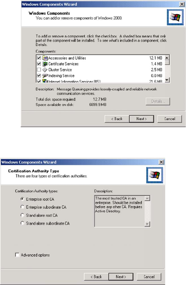
4. Click Next.
5. Select Enterprise root CA, and click Next.
6. Enter the information for the Certificate Authority, and click Next.
123
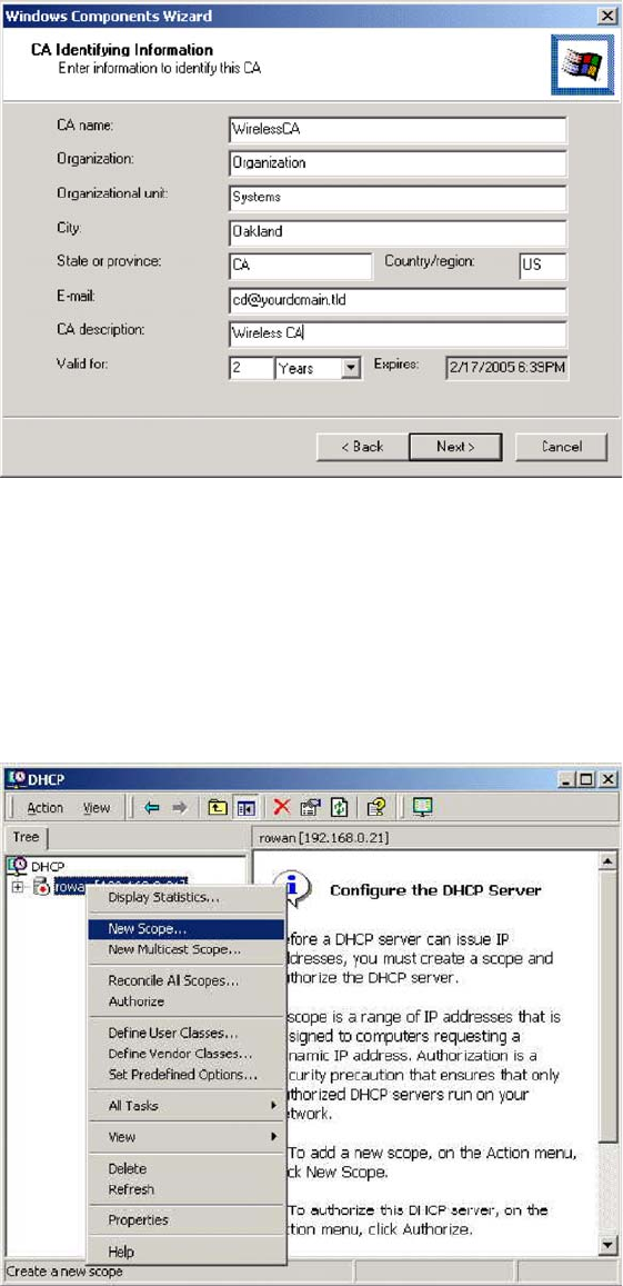
7. Click Next if you don't want to change the CA's configuration data.
8. Installation will warn you that Internet Information Services are running, and must be
stopped before continuing. Click OK, then Finish.
DHCP server configuration
1. Click on Start > Programs > Administrative Tools > DHCP.
2. Right-click on the server entry, and select New Scope.
3. Click Next when the New Scope Wizard Begins.
4. Enter the name and description for the scope, click Next.
124
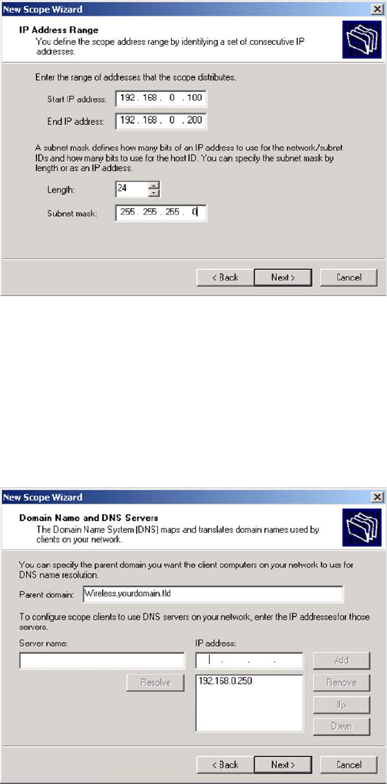
5. Define the IP address range. Change the subnet mask if necessary. Click Next.
6. Add exclusions in the address fields if required. If no exclusions are required, leave it
blank. Click Next.
7. Change the Lease Duration time if preferred. Click Next.
8. Select Yes, I want to configure these options now, and click Next.
9. Enter the router address for the current subnet. The router address may be left blank if
there is no router. Click Next.
10. For the parent domain, enter the domain you specified for the domain controller setup, and
enter the server's address for the IP address. Click Next.
11. If you don't want a WINS server, just click Next.
12. Select Yes, I want to activate this scope now. Click Next, then Finish.
125
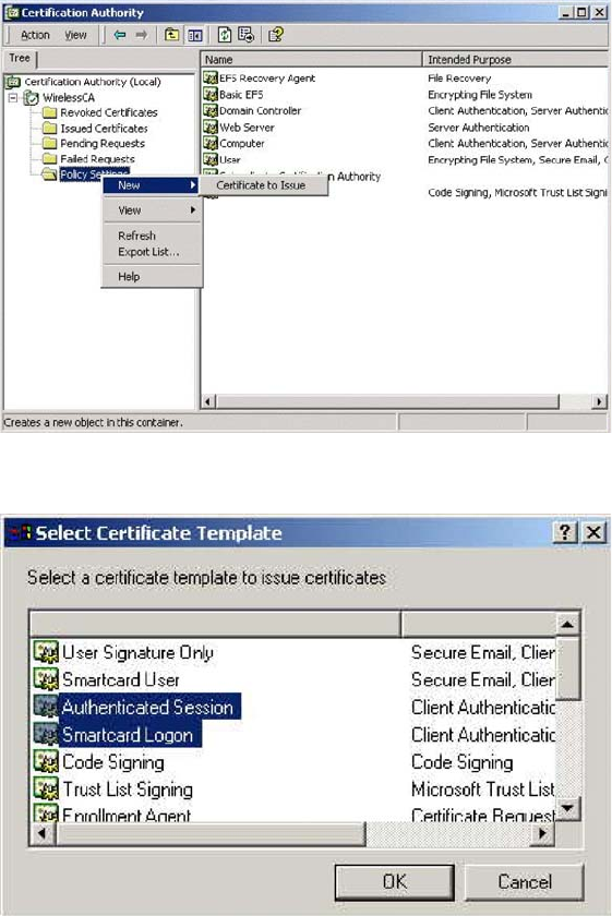
13. Right-click on the server, and select Authorize. It may take a few minutes to complete.
Certificate Authority Setup
1. Select Start > Programs > Administrative Tools > Certification Authority.
2. Right-click Policy Settings, and select New > Certificate to Issue.
3. Select Authenticated Session and Smartcard Logon (select more than one by holding
down the Ctrl key). Click OK.
4. Select Start > Programs > Administrative Tools > Active Directory Users and Computers.
5. Right-click on your active directory domain, and select Properties.
126
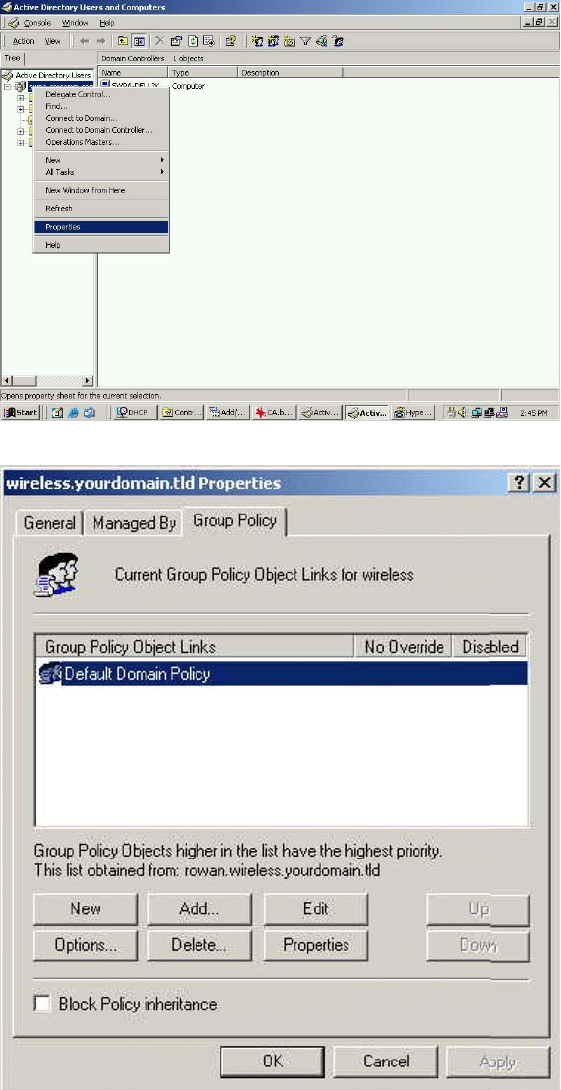
6. Select the Group Policy tab, chooseDefault Domain Policy then click Edit.
7. Select Computer Configuration > Windows Settings > Security Settings > Public Key
Policies, right-click Automatic Certificate Request Settings > New > Automatic
Certificate Request.
127
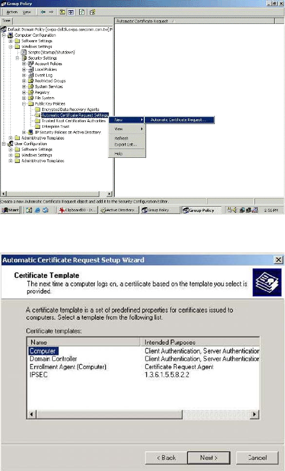
8. When the Certificate Request Wizard appears, click Next.
9. Select Computer, click Next.
10. Ensure that your Certificate Authority is checked, click Next.
11. Review the policy change information and click Finish.
12. Click
Start
>
Run
, type “cmd
”
and press Enter. Enter “secedit /refreshpolicy
machine_policy”. This command may take a few minutes to take effect.
128
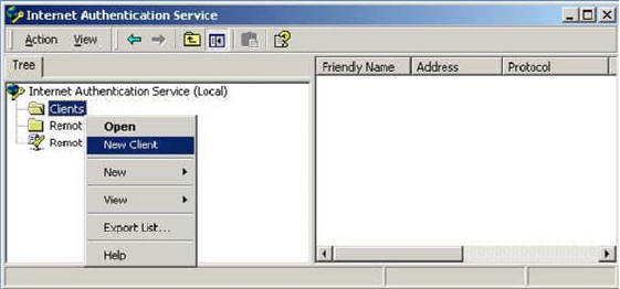
Internet Authentication Service (RADIUS) Setup
1. Select Start > Programs > Administrative Tools > Internet Authentication Service.
2. Right-click on Clients, and select New Client.
3. Enter a name for the access point, click Next.
4. Enter the address or name of the wireless access point, and set the shared secret, as
entered on the Security Settings of the wireless access point.
5. Click Finish.
6. Right-click on
Remote Access Policies
, select
New Remote Access Policy
.
7. Assuming you are using EAP-TLS, name the policy “eap-tls”, and click Next.
8. Click Add...
If you don't want to set any restrictions and a condition is required, select
Day-And-Time-
Restrictions
, and click Add...
129
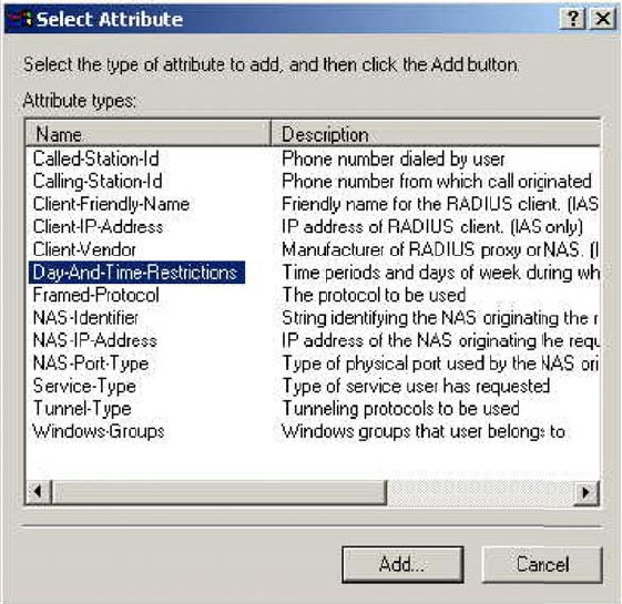
9. Click Permitted, then OK. Select Next.
10. Select
Grant remote access permission
. Click Next.
11. Click Edit Profile... and select the Authentication tab. Enable Extensible Authentication
Protocol, and select Smart Card
or
other Certificate. Deselect other authentication
methods listed. Click OK.
130
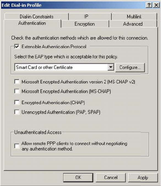
12. Select No if you don't want to view the help for EAP. Click Finish.
131
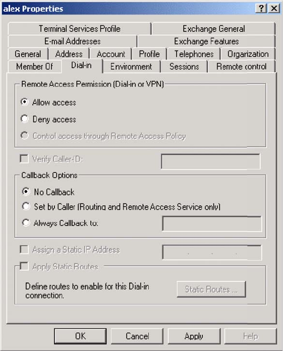
Remote Access Login for Users
1. Select Start > Programs > Administrative Tools> Active Directory Users and Computers.
2. Double-click on the user who you want to enable.
3. Select the Dial-in tab, and enable Allow access. Click OK.
802.1x Client Setup on Windows XP
Windows XP ships with a complete 802.1x client implementation. If using Windows 2000, you
can install SP3 (Service Pack 3) to gain the same functionality.
If you don't have either of these systems, you must use the 802.1x client software provided with
your wireless adapter. Refer to your vendor's documentation for setup instructions.
The following instructions assume:
xYou are using Windows XP.
xYou are connecting to a Windows 2000 server for authentication.
xYou already have a login (Username and password) on the Windows 2000 server.
132
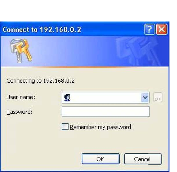
Client Certificate Setup
1. Connect to a network that doesn't require port authentication.
2. Start your Web browser. In the address box, enter the IP address of the Windows 2000
Server, followed by “/certsrv”, e.g., “http://192.168.0.2/certsrv”.
3. You will be prompted for a user name and password. Enter the User name and Password
assigned to you by your network administrator, and click OK.
133
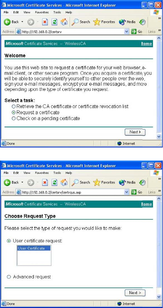
4. On the first screen (below), select Request a certificate, click Next.
5. Select User certificate request and selectUser Certificate, click Next.
6. Click Submit.
134
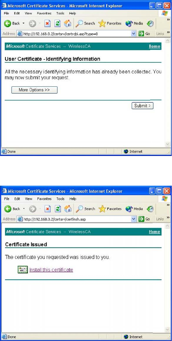
7. A message will be displayed,and the certificate will be returned to you.
Click Install this certificate.
8. You will receive a confirmation message. Click Yes.
135
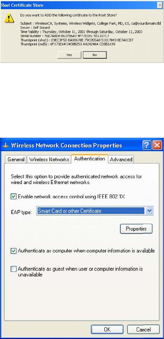
Certificate setup is now complete.
802.1x Authentication Setup
1. Select Start > Control Panel > Network Connections.
2. Right-click on the Wireless Network Connection, and select Properties.
3. Select the Authentication tab, and ensure that Enable network access control using IEEE
802.1X is selected, and Smart Card or other Certificate is selected from the EAP type.
136
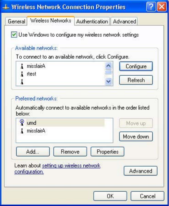
Encryption Settings
The encryption settings must match the access point’s on the wireless network you wish to join.
xWindows XP will detect any available wireless networks, and allow you to configure each
network independently.
xYour network administrator can advise you of the correct settings for each network.
802.1x networks typically use EAP-TLS. This is a dynamic key system, so there is no need
to enter key values.
Enabling Encryption
To enable encryption for a wireless network:
1. Click on the Wireless Networks tab.
2. Select the wireless network from the Available networks list, and click Configure.
3. Select and enter the correct values, as advised by your network administrator.
For example, to use EAP-TLS, you would enable Data encryption, and click the checkbox
for the setting The key is provided for me automatically, as shown below.
137
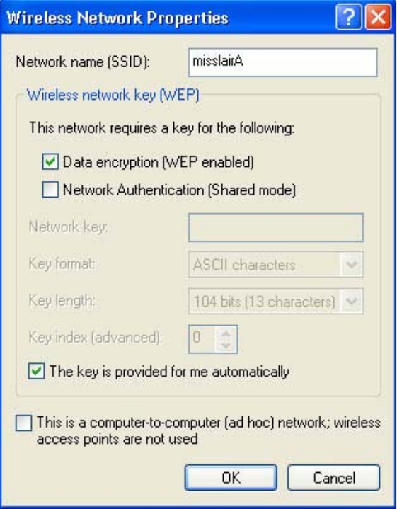
Setup for Windows XP and 802.1x client is now complete.
138
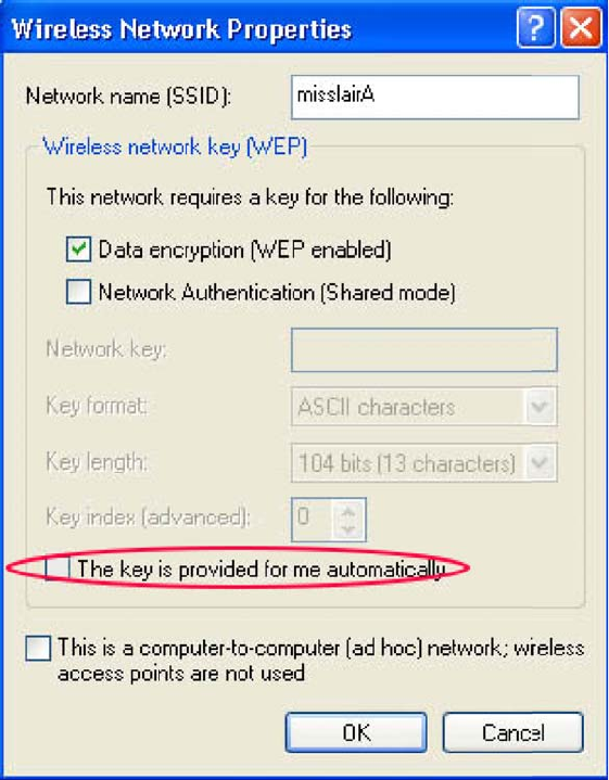
Using 802.1x Mode (without WPA)
This is very similar to using WPA-Enterprise.
The only difference is that on your client, you must NOT enable the setting The key is provided for
me automatically.
Instead, you must enter the WEP key manually, ensuring it matches the WEP key used on the
access point.
Note—On some systems, the 64-bit WEP key is shown as 40-bit and the 128-bit WEP key is
shown as 104-bit. This difference arises because the key input by the user is 24 bits less than
the key size used for encryption.
139
LNKPG-00333 Rev. A00
140