LINKSYS WUSB11-V28 Wireless-B USB Network Adapter User Manual WUSB11v2 8 ug Rev A
LINKSYS LLC Wireless-B USB Network Adapter WUSB11v2 8 ug Rev A
LINKSYS >
Part 2
STEP C
3. Using the velcro strip on the Adapter’s Wall Mount, attach the Adapter to the
velcro strip on your wall.
If your PC is running Windows XP, proceed to “Chapter 6: Driver
Installation and Configuration for Windows XP.”
If your PC is running Windows 98SE, Me, or 2000, the installation of the
Wireless-B USB Network Adapter is complete. If you want to check the
link information, search for available wireless networks, or make addi-
tional configuration changes, proceed to “Chapter 7: Using the WLAN
Monitor for Windows 98SE, Me, and 2000.”
13
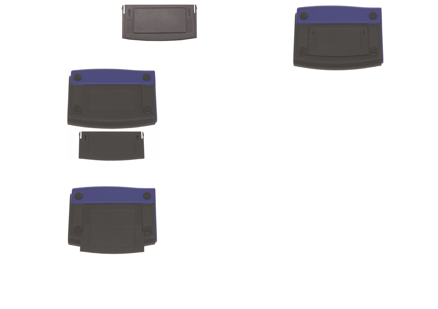
1. Attach the separate adhesive strip of vel-
cro to the wall where you will be mount-
ing the Adapter.
2. To attach the Wall Mount to the Adapter,
slide the Wall Mount into the grooves on
the back panel of the Adapter, as shown in
Steps A, B, and C.
STEP A
STEP B
12
Figure 5-6
Figure 5-7
Figure 5-8
Figure 5-9
1514
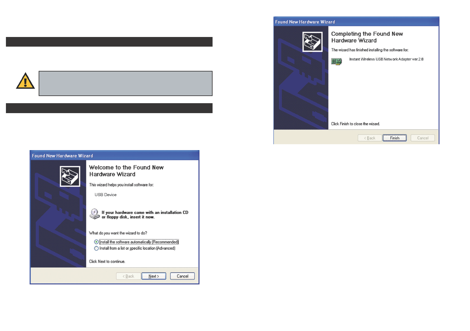
2. When Windows has finished installing the driver, click the Finish button.
You have now completed the driver installation for
the Wireless-B USB Network Adapter. To configure the Adapter, pro-
ceed to the next section, “Windows XP Wireless Zero Configuration.”
Figure 6-2
Chapter 6: Driver Installation and
Configuration for Windows XP
After connecting the Adapter to your computer, you will install the driver and
configure the Adapter.
1. Windows XP will automatically detect the Adapter. Insert the Setup CD-
ROM into your CD-ROM drive. Click the radio button next to Install the
software automatically (Recommended). Then click the Next button.
Important for Windows XP users: Do NOT run the Wireless USB
Network Adapter Setup Wizard. If the Setup Wizard runs automatical-
ly after the Setup CD-ROM has been inserted, click the Exit button.
Figure 6-1
Overview
Driver Installation for Windows XP
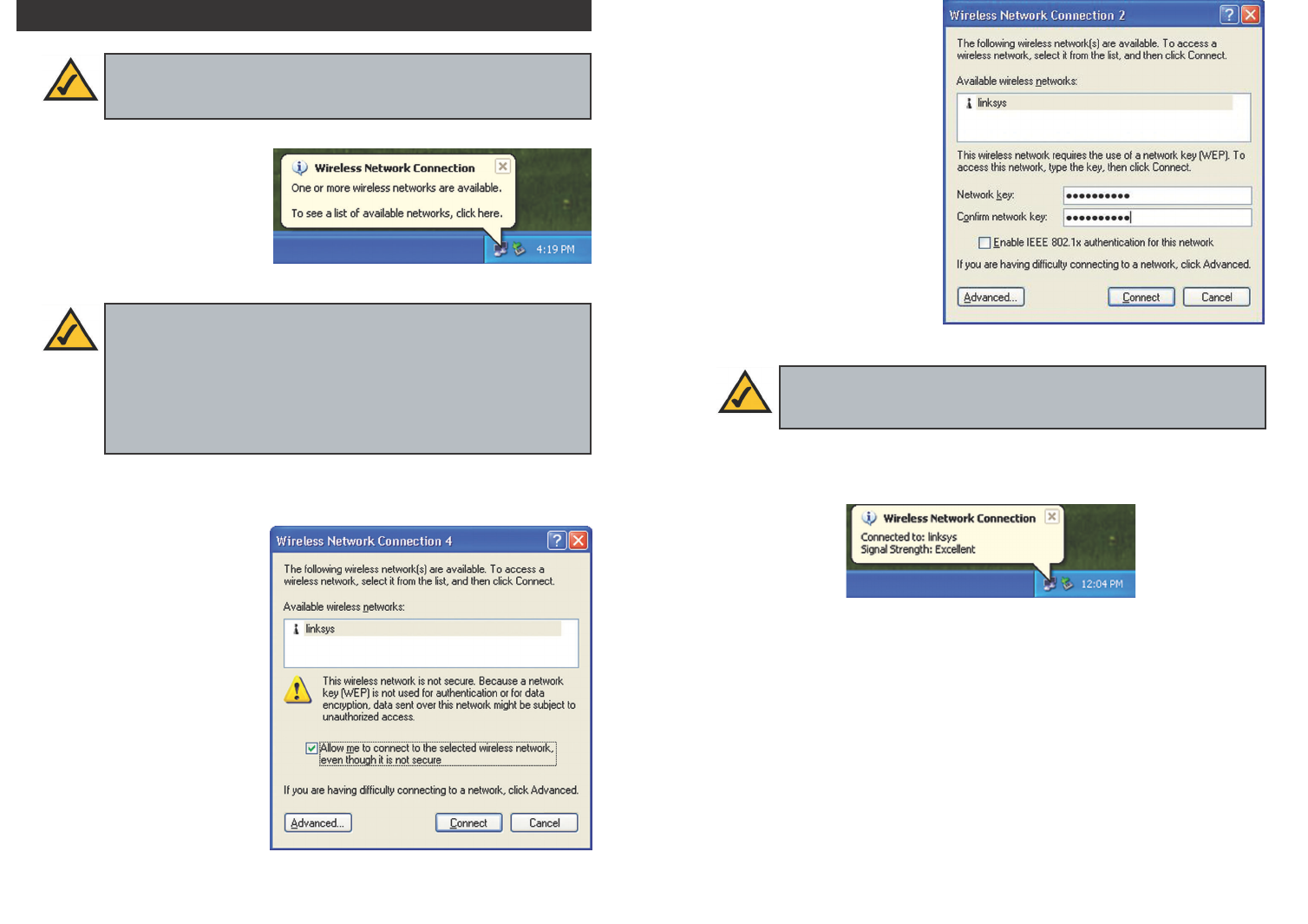
3. If WEP is enabled, the
screen in Figure 6-5 will
appear. Enter the WEP key
of your wireless network in
the Network key field, and
re-enter it in the Confirm
network key field. Then click
the Connect button, and go
to step 4.
4. The screen in Figure 6-6 will appear if your connection is active.
For more information about wireless networking on a Windows XP computer,
click Start and then Help and Support. Enter the keyword wireless in the
field provided, and press the Enter key.
Congratulations! The installation of the Wireless-B USB Network
Adapter is complete.
1716
1. After installing the Adapter,
the Windows XP Wireless
Zero Configuration icon
will appear in your comput-
er’s system tray (see Figure
6-3). Double-click the icon.
2. The screen that appears will show any available wireless network. Select
the network you want.
If this network has WEP
encryption enabled, go to
step 3.
If this network does not
have WEP encryption
enabled, then Figure 6-4
will appear. Make sure the
box next to Allow me to
connect to the selected
wireless network, even
though it is not secure is
checked. Then click the
Connect button, and go to
step 4.
Windows XP Wireless Zero Configuration
Note for Windows XP users: Windows XP has a built-in configura-
tion tool. Use Windows XP Wireless Zero Configuration (in the sys-
tem tray at the bottom of your screen) to configure the Adapter.
Figure 6-3
Figure 6-5
Note: Steps 2 and 3 are the instructions and screenshots for Windows
XP with Service Pack 1 installed.
If you have not installed Service Pack 1, select the network you want,
and click the Connect button. If the network has WEP encryption
enabled, enter the WEP key in the Network key field, and then click
the Connect button.
Note: Windows XP Wireless Zero Configuration does not support
the use of a passphrase. Enter the exact WEP key used by your access
point.
Figure 6-4
Figure 6-6
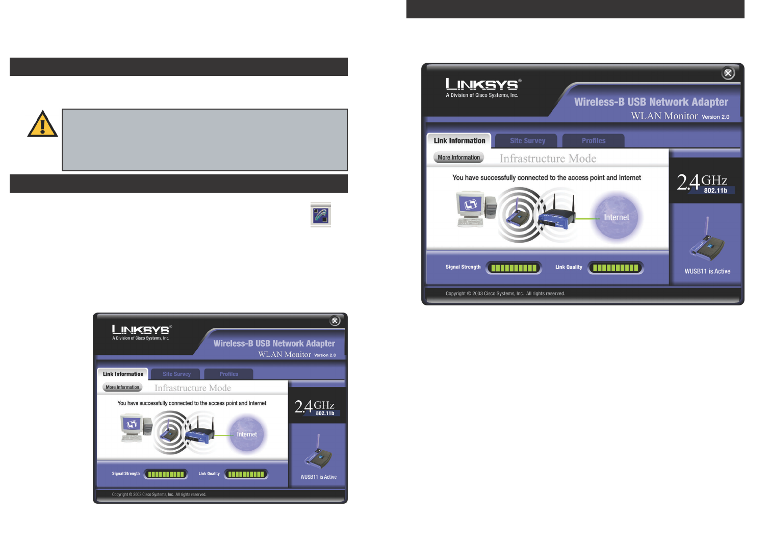
The Link Information screen displays network mode, signal strength, and link
quality information about the current connection. It also provides a button to
click for additional status information.
Ad-Hoc Mode or Infrastructure Mode - The screen indicates whether the
Adapter is currently working in ad-hoc or infrastructure mode.
Signal Strength - The Signal Strength bar indicates signal strength, from 0 to
100%.
Link Quality - The Link Quality bar indicates the quality of the wireless net-
work connection, from 0 to 100%.
Click the More Information button to view additional information about the
wireless network connection.
Click the X (Close) button in the upper right corner to exit the WLAN Monitor.
1918
Link Information
Figure 7-3
Chapter 7: Using the WLAN Monitor
for Windows 98SE, Me, and 2000
Use the WLAN Monitor to check the link information, search for available
wireless networks, or create profiles that hold different configuration settings.
After installing the Adapter, the Wireless-B USB Network
Adapter WLAN Monitor icon will appear in your system tray.
Double-click the icon (see Figure 7-1).
The Link Information screen will appear. From this screen, you can find out
how strong the current wireless signal is and how good the connection’s quali-
ty is. You can also click the More Information button to view additional sta-
tus information about the current wireless connection. To search for available
wireless networks, click the Site Survey tab. To perform configuration
changes, click
the Profiles
tab.
Figure 7-1
Figure 7-2
Important for Windows XP users: Windows XP has a built-in
configuration tool. Use the Windows XP Wireless Zero Configuration
(in the system tray at the bottom of your screen) to configure the
Adapter. See “Chapter 6: Driver Installation and Configuration for
Windows XP.”
Accessing the WLAN Monitor
Overview
21
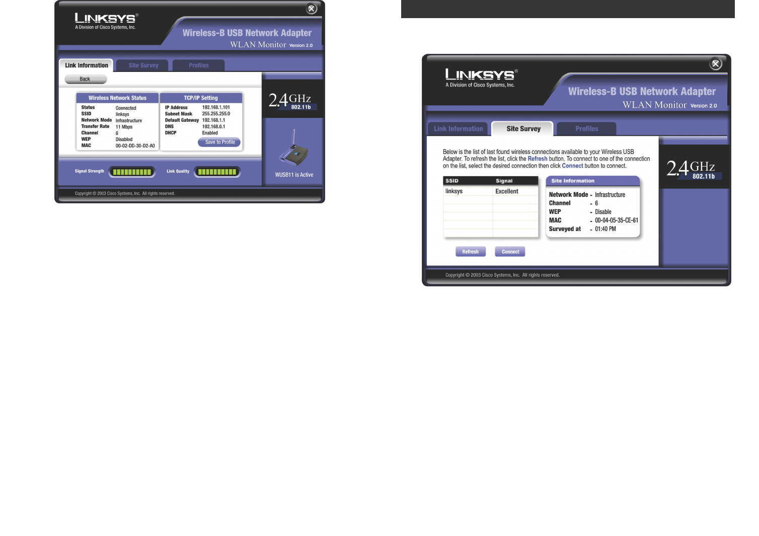
Wireless Network Status
Status - The status of the wireless network connection.
SSID - The SSID of the wireless network.
Network Mode - The wireless mode currently in use.
Transfer Rate - The data transfer rate of the current connection.
Channel - The channel to which the wireless network devices are set.
WEP - The status of the WEP encryption security feature.
MAC - The MAC address of the wireless network’s access point.
TCP/IP Setting
IP Address - The IP Address of the Adapter.
Subnet Mask - The Subnet Mask of the Adapter.
Default Gateway - The Default Gateway address of the Adapter.
DNS - The DNS address of the Adapter.
DHCP - The status of the DHCP client.
Save to Profile - Click the Save to Profile button to save the current settings
in a configuration profile. Then the Create connection profile screen will
appear. Enter a name for the new profile, and click the OK button.
Click the Back button to return to the initial Link Information screen.
Click the X (Close) button in the upper right corner to exit the WLAN Monitor.
20
The Site Survey screen displays a list of infrastructure and ad-hoc networks
available for connection.
For all networks detected, the following are listed:
SSID - The SSID, unique name, of the wireless network.
Signal - The qualitative strength of the wireless signal.
Site Information
For each network selected, the following settings are listed:
Network Mode - The wireless mode currently in use.
Channel - The channel to which the wireless network devices are set.
WEP - The status of the WEP encryption security feature.
MAC - The MAC address of the wireless network’s access point.
Surveyed at - The time at which the wireless network was scanned.
Refresh - Click the Refresh button to perform a new search for wireless
devices.
Figure 7-5
Site Survey
Figure 7-4