Laird Connectivity 60SIPT 802.11 ac/a/b/g/n + Bluetooth 4.2 module / 802.11 ac/a/b/g/n M.2 2230 + Bluetooth 4.2 module User Manual CS DS 60 2230C PRELIMINARY
Laird Technologies 802.11 ac/a/b/g/n + Bluetooth 4.2 module / 802.11 ac/a/b/g/n M.2 2230 + Bluetooth 4.2 module CS DS 60 2230C PRELIMINARY
Contents
- 1. Users Manual_60-2230C_SQG-60SIPT
- 2. Users Manual_60-SIPT_SQG-60SIPT
Users Manual_60-2230C_SQG-60SIPT
A
Datasheet
60-2230C
Version 1.0
60-2230C
Datasheet
Embedded Wireless Solutions Support Center:
http://ews-support.lairdtech.com
www.lairdtech.com/wireless
2
© Copyright 2017 Laird. All Rights Reserved
Americas: +1-800-492-2320
Europe: +44-1628-858-940
Hong Kong: +852 2923 0610
R
EVISION
H
ISTORY
Version
Date
Notes
Approver
1.0
TBD
Initial Version
Andrew Chen

60-2230C
Datasheet
Embedded Wireless Solutions Support Center:
http://ews-support.lairdtech.com
www.lairdtech.com/wireless
3
© Copyright 2017 Laird. All Rights Reserved
Americas: +1-800-492-2320
Europe: +44-1628-858-940
Hong Kong: +852 2923 0610
C
ONTENTS
1.
Scope 5
2.
Introduction 5
2.1
General Description 5
3.
60-2230C Features Summary 6
4.
Specifications 7
5.
WLAN Functional Description 13
6.
Bluetooth Functional Description 16
7.
Block Diagram 17
8.
Electrical Characteristics 18
8.1
Absolute Maximum Ratings 18
8.2
Recommended Operating Conditions 18
8.3
DC Electrical Characteristics 18
8.4
WLAN Radio Receiver Characteristics 19
8.5
WLAN Transmitter Characteristics 20
9.
Bluetooth Radio Characteristics 22
10.
SDIO Timing Requirements 24
10.1
SDR12, SDR25, SDR50 Mode (up to 100MHz) (1.8V) 24
10.2
SDR104 Mode (208MHz) (1.8V) 25
10.3
DDR50 Mode (50MHz) (1.8V) 26
11. USB Specifications 27
11.1
USB LS Driver and Receiver Parameters 27
11.2
USB FS Driver and Receiver Parameters 29
11.3
USB HS Driver and Receiver Parameters 30
12.
PCM interface specifications 31
13.
Pin Definitions 32
14.
Mechanical Specifications 35
15.
MOUNTING 35
16.
RF Layout Design Guidelines / Precautions 37
17.
Regulatory 37
17.1
Certified Antennas 37
18.
FCC and IC Regulatory 38
18.1
FCC 38
60-2230C
Datasheet
Embedded Wireless Solutions Support Center:
http://ews-support.lairdtech.com
www.lairdtech.com/wireless
4
© Copyright 2017 Laird. All Rights Reserved
Americas: +1-800-492-2320
Europe: +44-1628-858-940
Hong Kong: +852 2923 0610
18.1.1
Federal Communication Commission Interference Statement ....................................................... 38
18.1.2
FCC Caution ..................................................................................................................................... 38
18.1.3
Important Note ................................................................................................................................ 39
18.1.4
End Product Labeling ....................................................................................................................... 39
18.1.5Manual Information to the End User .................................................................................................... 39
18.2
Industry Canada 40
18.2.1Industry Canada Statement ................................................................................................................... 40
18.2.2
Antenna Information ....................................................................................................................... 40
18.2.3
Caution: ........................................................................................................................................... 41
18.2.4
Avertissement: ................................................................................................................................. 41
18.2.5
Radiation Exposure Statement ........................................................................................................ 41
18.2.6
Déclaration d'exposition aux radiations .......................................................................................... 41
18.2.7
Important Note ................................................................................................................................ 42
18.2.8
Note Important ................................................................................................................................ 42
18.2.9
End Product Labeling ....................................................................................................................... 42
18.2.10 Plaque signalétique du produit final ................................................................................................. 42
18.2.11 Manual Information to the End User................................................................................................ 42
18.2.12 Manuel d'information à l'utilisateur final ......................................................................................... 42
19.
European Union Regulatory 42
19.1EU Declarations of Conformity 43
20.
Ordering Information 44
20.1
General Comments 44
20.2
Labeling Requirements 45
60-2230C
Datasheet
Embedded Wireless Solutions Support Center:
http://ews-support.lairdtech.com
www.lairdtech.com/wireless
5
© Copyright 2017 Laird. All Rights Reserved
Americas: +1-800-492-2320
Europe: +44-1628-858-940
Hong Kong: +852 2923 0610
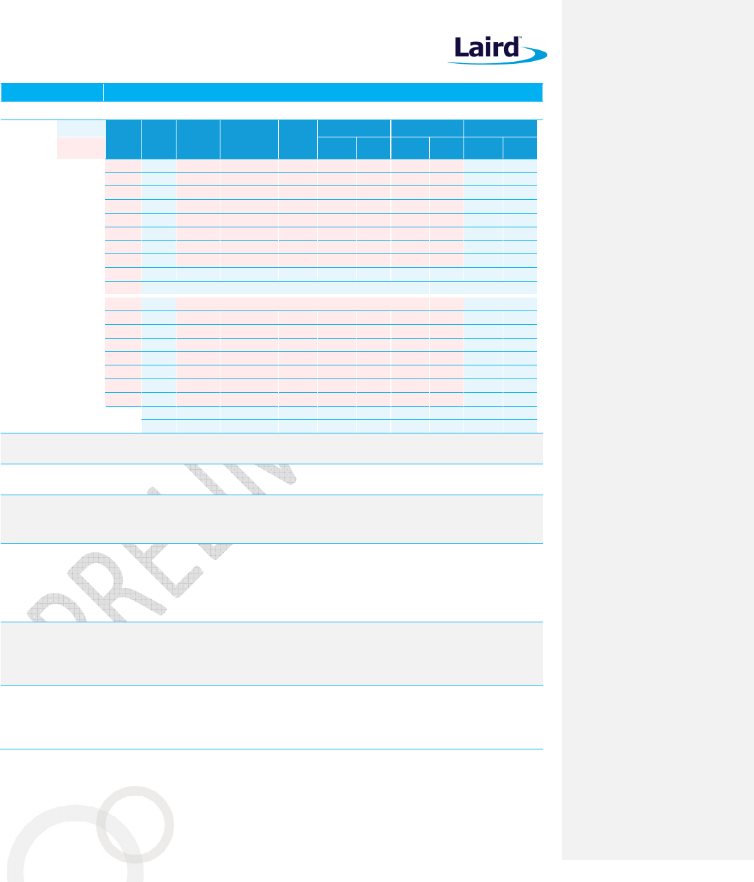
1. S
COPE
This document describes key hardware aspects of the Laird 60-2230C M.2 module providing either SDIO or
USB2.0 bus interface for WLAN connection and UART/SDIO/USB2.0 for Bluetooth
®
(including Low Energy or LE)
connection. This document is intended to assist device manufacturers and related parties with the integration of
this module into their host devices. Data in this document is drawn from the Marvell 88W8997 datasheet issued
in April 25, 2016.
Note that the information in this document is subject to change. Please contact Laird to obtain the most recent
version of this document.
2. I
NTRODUCTION
2.1 General Description
The 60-2230C module is a dual band 2x2 802.11ac WLAN plus Bluetooth 4.2 dual mode adapter; it complies with
M.2 key-E standard. The module provides both simultaneous and independent operation of the following:
IEEE 802.11ac (Wave 2), 2x2 receive Multi-User MIMO spatial stream multiplexing
with data rates up to MCS9 (866.7 Mbps)
Bluetooth (Class 1 and Class 2)
Bluetooth 4.2 (with Low Energy or LE)
Bluetooth Smart Ready operation
Three-way coexistence for WLAN and Bluetooth
Note: The Bluetooth
®
word mark and logos are registered trademarks owned by
Bluetooth SIG, Inc. and any use of such marks by Laird is under license. Other
trademarks and trade names are those of their respective owners.
Internal coexistence arbitration and a Mobile Wireless System (MWS) serial transport interface provide the
functionality for connecting an external Long Term Evolution (LTE).
The module integrates all WLAN and Bluetooth functionality into a single package which supports low-cost and
simple implementation along with flexibility for platform-specific customization. In addition, it has low power
consumption radio architecture and proprietary power save technologies to extended battery life.
On the DFS engine, the module supports 802.11h Dynamic Frequency Selection to detect the presence of radar
signals; support is extended to 80 MHz mode under the 802.11ac channelization modes. In addition, the E-DFS
(Enhanced DFS) scheme is designed to increase pulse detection rates for shorter (0.5 us, 0.8 us, 1 us), in-band
DFS pulses. The scheme is designed to minimize the false-alarm rate for out-of-band DFS pulse.
There are two interfaces for WLAN function:
SDIO 3.0 – Supports both 1-bit SDIO and 4-bit SDIO transfer modes at full clock range up to 208 MHz
USB 2.0
In addition, there are three interfaces for Bluetooth function:
SDIO
USB 2.0
High-Speed UART
Comment [JW1]: Do we really want
this sentence in there?
Comment [JW2]: We should add
the “2230” reference. So, the radio
“complies with the M.2 2230 E-Key
Standard”
Comment [JW3]: We should
probably add that the 60 series is
“Bluetooth 5 Ready”.
60-2230C
Datasheet
Embedded Wireless Solutions Support Center:
http://ews-support.lairdtech.com
www.lairdtech.com/wireless
6
© Copyright 2017 Laird. All Rights Reserved
Americas: +1-800-492-2320
Europe: +44-1628-858-940
Hong Kong: +852 2923 0610
The 60-2230C module also provides a PCM interface for master or slave mode; with the option of an 8-bit or 16-
bit width size.
Pins CON[0], CON[1], and CON[2] are configuration pins (operation mode). Currently, the default mode for the
SDIO/UART (WLAN/Bluetooth) interface is 000.
3. F
EATURES
S
UMMARY
The Laird 60-2230C device features are described in Table 1.
Table 1: 60-2230C of features
Feature Description
Radio Front End
Integrates the complete transmit/receive RF paths including band pass filter, diplexer, switches,
reference crystal oscillator, and power manage unit (PMU)
Supports 20/40/80 MHz channel bandwidth
WLAN
/Bluetooth share one antenna
Coexistence Coexistence arbitration for WLAN, Bluetooth, and LTE operation
Power Management
Dynamic Voltage Scaling (DVS) and Adaptive Voltage Scaling (AVS) feature supports the latest
Marvell SoC and processor power control scheme.
Pre-Calibration RF system-tested and calibrated in production.
Sleep Clock An external sleep clock of 32.768 KHz is required during power save mode.
Host Interface
SDIO 3.0 (4-bit and 1-bit), SDR 12/25/50 mode (up to 100MHz), USB 2.0 or PCIe for WLAN
SDIO 3.0, USB 2.0, HS-UART for Bluetooth HCI (compatible with any upper layer Bluetooth stack)
PCM digital audio interface for Bluetooth audio application.
Strap Value
CONFIG_HOST[2
-
0]
WLAN Bluetooth/
BLE
ROM Notes
000
SDIO
UART
-
001
SDIO
SDIO
-
010
PCIe
USB 2.0
Initial USB 2.0 PHY
and
COM PHY PCIe portion
011
PCIe
UART
Initial COM PHY PCIe portion only
100
USB 2.0
UART
Initial USB 2.0 PHY
and
COM PHY PCIe USB 3.0
101
USB 2.0
USB 2.0
Initial USB 2.0 PHY only
Reference Frequency
Incorporates a 40 MHz reference frequency source in package
An external sleep clock is recommended for minimal current consumption. If no sleep clock
input is provided, an internal sleep clock (derived from the reference clock) is used. An
approximate 50 uA current increase on the 3.3V rail.
Advanced WLAN
A-MPDU RX (de-aggregation) and TX (aggregation) supports 802.11ac single-MPDU A-MPDU
Multi-BSS/Station
Transmit rate adaption, transmit power control
Modulation and coding scheme (MCS):
– 802.11ac—MCS0-9 Nsts=1 and 2
– 802.11n—MCS0-15
Dynamic frequency selection (DFS) – Radar detection
20/40/80 MHz channel bandwidths support
On-chip gain selectable LNA with optimized noise figure and power consumption
Internal PA with optimized gain distribution for linearity and noise performance
Support Wild variety of WLAN encryption: TKIP/WEP/AES
Comment [JW4]: We need to
remove references to PCIE as the
M.2 module does not support PCIE
60-2230C
Datasheet
Embedded Wireless Solutions Support Center:
http://ews-support.lairdtech.com
www.lairdtech.com/wireless
7
© Copyright 2017 Laird. All Rights Reserved
Americas: +1-800-492-2320
Europe: +44-1628-858-940
Hong Kong: +852 2923 0610
Feature Description
Advanced Bluetooth
Bluetooth 4.2 (BDR/EDR/LE), Bluetooth Class 1
Supports the following data rates: 1 Mbps (GFSK), 2 Mbps ( /4-DQPSK), 3 Mbps (8-DPSK)
Digital audio interface with PCM/TDM interface for voice application
Adaptive Frequency Hopping (AFH) using Package Error Rate (PER)
Standard SDIO or UART HCI transport layer
WLAN/Bluetooth coexistence protocol support
Shared LNA with WLAN/Bluetooth
Encryption (AES) support
4. S
PECIFICATIONS
Table 2: Specifications
Feature Description
Physical Interface 84-pin LGA package (including 16 thermal ground pad under the package)
Wi-Fi Interface 1-bit or 4-bit Secure Digital I/O; PCIe v3.0 Gen1/Gen2 (2.5/5 Gbps); USB 2.0
Bluetooth/
BLE Interface
Host Controller Interface (HCI) using High Speed UART, SDIO, USB 2.0
Strap Value
CONFIG_HOST[2
-
0]
WLAN Bluetooth
/BLE
ROM Notes
000
SDIO
UART
-
001
SDIO
SDIO
-
010
PCIe
USB 2.0
Initial USB 2.0 PHY
and
COM PHY PCIe portion
011
PCIe
UART
Initial COM PHY PCIe portion only
100
USB 2.0
UART
Initial USB 2.0 PHY
and
COM PHY PCIe USB 3.0
101
USB 2.0
USB 2.0
Initial USB 2.0 PHY only
Main Chip Marvell 88W8997 (WLAN/BT); Marvell 88PG823 (PMU)
Input Voltage
Requirements DC 3.3 V ±10%
I/O Signalling
Voltage DC 3.3 V ± 10% or DC 1.8 V ± 10%
Peak Current
consumption,
VCC=VIO = 3.3 volts
(At maximum
transmit power
setting)
Note: Reset refers
to the radio are in
reset, both Wi-fi and
BT reset are
asserted.
MIMO 2x 2 operations.
802.11b (with BT in standby) @ 18 dBm 1 Mbps
Transmit: XX mA Receive: XX mA
802.11g (with BT in standby) @ 18 dBm 6 Mbps
Transmit: XX mA Receive: XX mA
802.11a (with BT in standby) @ 18 dBm 6 Mbps
Transmit: XX mA Receive: XX mA
802.11n (2.4 GHz/40MHz) (with BT in standby) @ 16 dBm MCS0
Transmit: XX mA Receive: XX mA
802.11n (5.0 GH/40MHz) (with BT in standby) @ 16 dBm MCS0
Transmit: XX mA Receive: XX mA
802.11ac (5.0 GH/80MHz) (with BT in standby) @ 14 dBm MCS0
Transmit: XX mA Receive: XX mA
Bluetooth (with Wi-Fi in standby)
Transmit: XX mA Receive: XX mA
Reset:
XXX mA
Comment [JW5]: Please Addd
“Bluetooth 5 Ready” in there
somewhere. It’s an important
value-add for this radio
Comment [JW6]: No PCIE
Comment [JW7]: Andrew, do we
have these numbers?
60-2230C
Datasheet
Embedded Wireless Solutions Support Center:
http://ews-support.lairdtech.com
www.lairdtech.com/wireless
8
© Copyright 2017 Laird. All Rights Reserved
Americas: +1-800-492-2320
Europe: +44-1628-858-940
Hong Kong: +852 2923 0610
Feature Description
Operating
Temperature
-30° to 85°C (-22° to 185°F)
Operating Humidity
10 to 90% (non-condensing)
Storage
Temperature
-40° to 85°C (-40° to 185°F)
Storage Humidity 10 to 90% (non-condensing)
Maximum
Electrostatic
Discharge
Conductive 4KV; Air coupled 8KV follow EN61000-4-2
Size 13 mm (length) x 14 mm (width) x 1.87 mm (thickness)
Weight TBD g
Wi-Fi Media Direct Sequence-Spread Spectrum (DSSS)
Complementary Code Keying (CCK)
Orthogonal Frequency Divisional Multiplexing (OFDM)
Bluetooth Media Frequency Hopping Spread Spectrum (FHSS)
Wi-Fi Media Access
Protocol
Carrier sense multiple access with collision avoidance (CSMA/CA)
A-MPDU Rx (De-aggregation) and Tx (aggregation) (802.11ac single-MPDU A-MPDU)
Network
Architecture Types
Infrastructure and ad-hoc
Wi-Fi Standards IEEE 802.11a, 802.11b, 802.11d, 802.11e, 802.11g, 802.11h, 802.11i, 802.11n, 802.11r, 802.11ac
Bluetooth
Standards
Bluetooth version 2.1 with Enhanced Data Rate
Bluetooth 4.2 (Bluetooth Low Energy or BLE)
Wi-Fi Data Rates
Supported
Support 802.11 ac/a/b/g/n 2X2 MIMO
802.11b (DSSS, CCK) 1, 2, 5.5, 11 Mbps
802.11a/g (OFDM) 6, 9, 12, 18, 24, 36, 48, 54 Mbps
802.11n (OFDM, HT20/HT40, MCS 0-15)
802.11ac (OFDM, HT20, MCS0-8; OFDM HT40/HT80, MCS 0-9)
Comment [JW8]: “Bluetooth 5
(Coming Soon)”
Comment [JW9]: “MU-MIMO” or
“802.11ac Wave 2”
60-2230C
Datasheet
Embedded Wireless Solutions Support Center:
http://ews-support.lairdtech.com
www.lairdtech.com/wireless
9
© Copyright 2017 Laird. All Rights Reserved
Americas: +1-800-492-2320
Europe: +44-1628-858-940
Hong Kong: +852 2923 0610
Feature Description
Modulation Table BPSK, QPSK, CCK, 16-QAM, 64-QAM, and 256-QAM.
802.11ac HT
MCS
Index
VHT
MCS
Index
Spatial
Streams
Modulation
Coding
20 MHz 40 MHz 80 MHz
802.11n No SGI
SGI No SGI
SGI No SGI
SGI
0 0 1 BPSK 1/2 6.5 7.2 13.5 15 29.3 32.5
1 1 1 QPSK 1/2 13 14.4 27 30 58.5 65
2 2 1 QPSK 3/4 19.5 21.7 40.5 45 87.8 97.5
3 3 1 16-QAM 1/2 26 28.9 54 60 117 130
4 4 1 16-QAM 3/4 39 43.3 81 90 175.5 195
5 5 1 64-QAM 2/3 52 57.8 108 120 234 260
6 6 1 64-QAM 3/4 58.5 65 121.5 135 263.3 292.5
7 7 1 64-QAM 5/6 65 72.2 135 150 292.5 325
8 1 256-QAM 3/4 78 86.7 162 180 351 390
9 1 256-QAM 5/6 N/A N/A 180 200 390 433.3
8 0 2 BPSK 1/2 13 14.4 27 30 58.5 65
9 1 2 QPSK 1/2 26 28.9 54 60 117 130
10 2 2 QPSK 3/4 39 43.3 81 90 175.5 195
11 3 2 16-QAM 1/2 52 57.8 108 120 234 260
12 4 2 16-QAM 3/4 78 86.7 162 180 351 390
13 5 2 64-QAM 2/3 104 115.6
216 240 468 520
14 6 2 64-QAM 3/4 117 130.3
243 270 526.5 585
15 7 2 64-QAM 5/6 130 144.4
270 300 585 650
8 2 256-QAM 3/4 156 173.3
324 360 702 180
9 2 256-QAM 5/6 N/A N/A 360 400 780 866.7
802.11ac/n
Spatial Streams
2 (2x2 MIMO)
Bluetooth Data
Rates Supported
1, 2, 3 Mbps
Bluetooth
Modulation
GFSK@ 1 Mbps
Pi/4-DQPSK@ 2 Mbps
8-DPSK@ 3 Mbps
Regulatory Domain
Support
FCC (Americas, Parts of Asia, and Middle East)
ETSI (Europe, Middle East, Africa, and Parts of Asia)
IC (Industry Canada)
MIC (Japan) (formerly TELEC) – Option
KC (Korea) (formerly KCC) – Option
2.4 GHz Frequency
Bands
ETSI: 2.4 GHz to 2.483 GHz
FCC: 2.4 GHz to 2.473 GHz
MIC: 2.4 GHz to 2.495 GHz
KC: 2.4 GHz to 2.483 GHz
2.4 GHz Operating
Channels
(Wi-Fi)
ETSI: 13 (3 non-overlapping)
FCC: 11 (3 non-overlapping)
MIC: 14 (4 non-overlapping)
KC: 13 (3 non-overlapping)
60-2230C
Datasheet
Embedded Wireless Solutions Support Center:
http://ews-support.lairdtech.com
www.lairdtech.com/wireless
10
© Copyright 2017 Laird. All Rights Reserved
Americas: +1-800-492-2320
Europe: +44-1628-858-940
Hong Kong: +852 2923 0610
Feature Description
5 GHz Frequency
Bands
ETSI
5.15 GHz to 5.35 GHz (Ch 36/40/44/48/52/56/60/64)
5.47 GHz to 5.725 GHz (Ch 100/104/108/112/116/120/124/128/132/136/140/144)
FCC
5.15 GHz to 5.35 GHz (Ch 36/40/44/48/52/56/60/64)
5.47 GHz to 5.725 GHz (Ch 100/104/108/112/116/120/124/128/132/136/140/144
5.725 GHz to 5.825 GHz(Ch 149/153/157/161/165)
MIC (Japan)
5.15 GHz to 5.35 GHz (Ch 36/40/44/48/52/56/60/64)
5.47 GHz to 5.725 GHz (Ch 100/104/108/112/116/120/124/128/132/136/140/144)
KC
5.15 GHz to 5.35 GHz (Ch 36/40/44/48/52/56/60/64)
5.47 GHz to 5.725 GHz (Ch 100/104/108/112/116/120/124)
5.725 GHz to 5.825 GHz (Ch 149/153/157/161)
5 GHz Operating
Channels (Wi-Fi)
ETSI: 19 non-overlapping; FCC: 24 non-overlapping
MIC (Japan): 19 non-overlapping; KC: 19 non-overlapping
Transmit Power
Note: Transmit
power on each
channel varies
according to
individual country
regulations. All
values are nominal
with +/-2 dBm
tolerance at room
temperature.
Tolerance could be
up to +/-2.5 dBm
across operating
temperature.
Note:
HT20 – 20 MHz-
wide channels
HT40 – 40 Mhz-wide
channels
HT80 – 80 MHz-
wide channels
802.11a
6 Mbps
18 dBm (63 mW)
54 Mbps
1
6
dBm (
40
mW)
802.11b
1 Mbps
18 dBm (63 mW)
11 Mbps
18 dBm (63 mW)
802.11g
6 Mbps
18 dBm (63
mW)
54 Mbps
1
6
dBm (
40
mW)
802.11n (2.4/5 GHz)
6.5 Mbps (MCS0
-
5/MCS8
-
13;HT20
)
18 dBm (63 mW)
65 Mbps (MCS6-7/MCS14-15;HT20)
13.5Mbps(MCS0-5/MCS8-13;HT40)
135Mbps (MCS6
-
7/MCS14
-
15;HT40)
16 dBm (40 mW)
16 dBm (40 mW)
14 dBm (25 mW)
802.11ac (5 GHz)
6.5
/13
Mbps
(MCS0
-
6;Ntst=1,2;HT20
)
18 dBm (63 mW)
78/156 Mbps (MCS7-8;Ntst=1,2;HT20)
13.5/27Mbps (MCS0-6;Ntst=1,2;HT40)
180/360Mbps (MCS7-9;Ntst=1,2;HT40)
29.3/58.5 Mbps (MCS0-5;Ntst=1,2;HT80)
263.3/526.5 Mbps (MCS6-8;Ntst=1,2;HT80)
390/780 Mbps
(MCS9;Ntst=1,2;HT80)
16 dBm (40 mW)
16 dBm (40 mW)
14 dBm (25 mW)
14 dBm (25 mW)
12 dBm (15.8 mW)
10 dBm (10
mW)
Bluetooth
1 Mbps
(1DH5)
10
dBm (
12.5
mW)
2 Mbps
7
dBm
(
6.3
mW)
3 Mbps
BLE (1
Mbps)
7 dBm (6.3 mW)
7 dBm
(
6.3
mW)
60-2230C
Datasheet
Embedded Wireless Solutions Support Center:
http://ews-support.lairdtech.com
www.lairdtech.com/wireless
11
© Copyright 2017 Laird. All Rights Reserved
Americas: +1-800-492-2320
Europe: +44-1628-858-940
Hong Kong: +852 2923 0610
Feature Description
Typical Receiver
Sensitivity
(PER <= 10%)
Note: All values
nominal, +/-3 dBm.
Sensitivity on CH13
(WLAN)/CH78 (BT)
will decade up to 4-
6dB.
802.11a:
6 Mbps -89 dBm
54 Mbps -74 dBm
802.11b:
1 Mbps -95 dBm
11 Mbps -90 dBm (PER<8%)
802.11g:
6 Mbps -91 dBm
54 Mbps -75 dBm
802.11n (2.4 GHz)
6.5 Mbps (MCS0;HT20) -91 dBm
65 Mbps (MCS7;HT20)
13.5Mbps(MCS0;HT40)
135Mbps (MCS7;HT40)
-73 dBm
-85 dBm
-70 dBm
802.11n (5 GHz)
6.5 Mbps (MCS0;HT20) -89 dBm
65 Mbps (MCS7;HT20)
13.5Mbps(MCS0;HT40)
135Mbps (MCS7;HT40)
-70 dBm
-86 dBm
-69 dBm
802.11ac (5 GHz)
6.5 Mbps
(MCS0
;HT20
)
-
89 dBm
78 Mbps (MCS8;HT20)
13.5 Mbps (MCS0;HT40)
180 Mbps (MCS9;HT40)
29.3 Mbps (MCS0;HT80)
390/780 Mbps (MCS9;HT80)
-67 dBm
-86 dBm
-63 dBm
-81 dBm
-
60 dBm
Bluetooth:
1 Mbps (1DH5)
2Mbps (2DH5)
-95 dBm
-94 dBm
3 Mbps (3DH5) -88 dBm
BLE -95 dBm
Operating Systems
Supported
Windows Mobile 5.0, 6.0, 6.1, 6.5
Windows Embedded Compact (CE) 5.0, 6.0, 7.0, 2013
Linux 2.6.x, 3.x.x, 4.0.x kernel
Android 4.1.2 (Jellybean) and forward
Comment [JW10]: No Windows
support on the 60 Series
Comment [JW11]: Linux Kernel 3.x
and newer
Android 5.x and newer
60-2230C
Datasheet
Embedded Wireless Solutions Support Center:
http://ews-support.lairdtech.com
www.lairdtech.com/wireless
12
© Copyright 2017 Laird. All Rights Reserved
Americas: +1-800-492-2320
Europe: +44-1628-858-940
Hong Kong: +852 2923 0610
Feature Description
Security Standards
Wireless Equivalent Privacy (WEP)
Wi-Fi Protected Access (WPA)
IEEE 802.11i (WPA2)
Encryption
Wireless Equivalent Privacy (WEP, RC4 Algorithm)
Temporal Key Integrity Protocol (TKIP, RC4 Algorithm)
Advanced Encryption Standard (AES, Rijndael Algorithm)
Encryption Key Provisioning
Static (40-bit and 128-bit lengths)
Pre-Shared (PSK)
Dynamic
802.1X Extensible Authentication Protocol Types
EAP-FAST
EAP-TLS
EAP-TTLS
PEAP
-
GTC
PEAP-MSCHAPv2
PEAP-TLS
LEAP
Compliance
Note: All regulatory
certifications
are currently
pending.
ETSI Regulatory Domain
EN 300 328
EN 301 489-1
EN 301 489-17
EN 301 893
EN 60950-1
EU 2002/95/EC (RoHS)
FCC Regulatory Domain
FCC 15.247 DTS – 802.11b/g (Wi-Fi) – 2.4 GHz
FCC 15.407 UNII – 802.11a (Wi-Fi) – 5 GHz
FCC 15.247 DSS – BT 2.1
Industry Canada
RSS-247 – 802.11a/b/g/n (Wi-Fi) – 2.4 GHz, 5.8 GHz, 5.2 GHz, and 5.4 GHz
RSS-247 – BT 2.1
Certifications Wi-Fi Alliance
802.11a, 802.11b, 802.11g , 802.11n, 802.11ac
WPA Enterprise
WPA2 Enterprise
Cisco Compatible Extensions (Version 4)
Bluetooth
®
SIG Qualification
Warranty Three Year Warranty
All specifications are subject to change without notice
Comment [JW12]: We should list
that EAP types are “supplicant
software dependent”. Since we are
supporting various software builds
with the 60 Series, some of the
features will rely on the software
Comment [JW13]: We will have
more Wi-Fi Alliance certs. I’m not
exactly sure which ones yet, but we
will have more.
Comment [JW14]: We won’t have
CCX certification on the 60 Series.
At least, that’s not the plan at this
moment
60-2230C
Datasheet
Embedded Wireless Solutions Support Center:
http://ews-support.lairdtech.com
www.lairdtech.com/wireless
13
© Copyright 2017 Laird. All Rights Reserved
Americas: +1-800-492-2320
Europe: +44-1628-858-940
Hong Kong: +852 2923 0610
5. WLAN
F
UNCTIONAL
D
ESCRIPTION
The 60-2230C M2 module is designed based on the 60-SIPT SiP. It is optimized for high-speed, reliable, and low-
power embedded applications. It is integrated with dual-band WLAN (2.4 GHz/5 GHz) and Bluetooth 4.2. Its
functionality includes the following:
Improved throughput on the link due to frame aggregation, RIFS (reduced inter-frame spacing), and half-
guard intervals.
Support for STBC (Space Time Block Codes) and LDPC (Low Density Parity Check) codes.
Improved 11n performance due to features such as 11n frame aggregation (A-MPDU and A-MSDU) and
low-overhead host-assisted buffering (RX A-MSDU and RX A-MPDU). These techniques can improve
performance and efficiency of applications involving large bulk data transfers such as file transfers or high-
resolution video streaming.
IEEE 802.11 ac (Wave 2), 2X2 receive Multi-User MIMIO (MU-MIMO) spatial stream multiplexing with data
rate up to MCS9 (866.7 Mbps).
Additional functionality is listed in Table 3.
Table 3: WLAN functions
Feature Description
WLAN MAC Frame Exchange at the MAC level to deliver data
Received frame filtering and validation (Cyclic Redundancy Check (CRC))
Generation of MAC header and trailer information (MAC protocol Data Units (MPDUs))
Fragmentation of data frames (MAC Service Data Units (MSDUs)
Access Mechanism support for fair access to shared wireless medium through (DCF and EDCA)
A-MPDU Aggregation/Deaggregation (support 802.11ac single –MPDU A-MPDU)
20/40/80 MHz channel Coexistence
RIFS Burst Receive
Management Information Base
Radio Resource Measurement
Quality of Service
Block Acknowledgement
802.11ac Downlink MU-MIMO (receive)
Dynamic Frequency Selection
Beamforming
TIM Frame TX and RX
Multi-BSS/Station
Transmit Rate Adaptation.
Transmit Power Control
60-2230C
Datasheet
Embedded Wireless Solutions Support Center:
http://ews-support.lairdtech.com
www.lairdtech.com/wireless
14
© Copyright 2017 Laird. All Rights Reserved
Americas: +1-800-492-2320
Europe: +44-1628-858-940
Hong Kong: +852 2923 0610
Feature Description
WLAN Base Band
802.11ac 2x2 MU
-
MIMO (with on
-
chip Marvell RF radio)
Backward compatibility with legacy 802.11 n/a/b/g technology
WLAN/Bluetooth LNA sharing
PHY rate up to 866.7Mbps
20MHz bandwidth/channel, 40MHz bandwidth/channel, upper/lower 20MHz packets in 40MHz
channel, 20MHz duplicate legacy packets in 40MHz channel operation
80MHz bandwidth/channel, 4 positions of 20MHz packets in 80MHz channel, upper/lower
40MHz packets in 80MHz channel, 20MHz quadruplicate legacy packets in 80MHz channel mode
operation
Modulation and Coding Scheme (MCS): 802.11 ac (MCS0-9. Nsts=1/2); 802.11n (MCS0-15)
Dynamic Frequency Selection (DFS) (Radar detection)
– Enhanced radar detection for long and short pulse radar
– Enhanced AGC scheme for DFS channel
– Japan DFS requirements for W53 and W56
802.11 K Radio Resource Measurement
802.11ac /802.11n optional MIMO features:
– 20/40/80 MHz Coexistence with middle-packaged detection (GI detection) for enhanced CCA.
– 1 spatial stream STBC reception and transmission
– LDPC transmission and reception for 802.11ac and 802.11n
– 256 QAM (MCS8-9) modulations supported
– Short guard interval
– RIFS on receive path for 802.11n packets
– 802.11n Greenfield TX/RX
Power Save Feature
WLAN Security WLAN Encryption features supported include:
Temporal Key Integrity Protocol (TKIP)/Wired Equivalent Privacy (WEP)
Advanced Encryption Standard (AES)/Counter-Mode/CBC-MAC Protocol (CCMP)
Advanced Encryption Standard (AES)/Cipher-Based Message Authentication Code (CMAC)
Advanced Encryption Standard (AES)/Galois/Counter Mode Protocol (GCMP)
WLAN Authentication and Private Infrastructure (WPAI)
60-2230C
Datasheet
Embedded Wireless Solutions Support Center:
http://ews-support.lairdtech.com
www.lairdtech.com/wireless
15
© Copyright 2017 Laird. All Rights Reserved
Americas: +1-800-492-2320
Europe: +44-1628-858-940
Hong Kong: +852 2923 0610
Feature Description
WLAN Channel Channel frequency supported.
20 MHz 40 MHz 80 MHz
Channel
Freq.
(MHz) Channel
Freq.
(MHz) Channel
Freq.
(MHz)
Channel
Freq.
(MHz)
1 2412 36 5180 1-5 2422 42 5210
2 2417 40 5200 2-6 2427 58 5290
3 2422 44 5220 3-7 2432 74 5370
4
2427
48
5240
4
-
8
2437
90
5410
5 2432 52 5260 5-9 2422 106 5530
6 2437 56 5280 6-10 2447 122 5610
7 2422 60 5300 7-11 2452 138 5690
8 2447 64 5320 36-40 5190 155 5775
9 2452 100 5500 44-48 5230
10 2457 104 5520 52-56 5270
11 2462 108 5540 60-64 5310
12
2467
112
5560
68
-
72
5350
13 2472 116 5580 76-80 5390
120 5600 84-88 5430
124 5620 92-96 5470
128 5640 100-104
5510
132 5660 108-112
5550
136 5680 116-120
5590
140
5700
124
-
128
5630
144
5720
132
-
136
5670
149
5745
140
-
144
5710
153 5765 149-153
5755
157 5785 157-161
5795
161 5805
165 5825
60-2230C
Datasheet
Embedded Wireless Solutions Support Center:
http://ews-support.lairdtech.com
www.lairdtech.com/wireless
16
© Copyright 2017 Laird. All Rights Reserved
Americas: +1-800-492-2320
Europe: +44-1628-858-940
Hong Kong: +852 2923 0610
6. B
LUETOOTH
F
UNCTIONAL
D
ESCRIPTION
The 60-2230C Bluetooth (BT) block is based on the 60-SIPT SiP that already has fully-integrated Bluetooth
baseband and radio. Several features and functions are listed in Table 4.
Table 4: Bluetooth functions
Feature Description
Bluetooth Interface
Voice interface:
Hardware support for continual PCM data transmission/reception without processor
overhead.
Standard PCM clock rates from 64 kHz to 2.048 MHz with multi-slot handshake and
synchronization.
A-law, U-law, and linear voice PCM encoding/decoding.
SDIO interface
High-Speed UART interface
USB 2.0
Bluetooth Core
functionality
Bluetooth 4.2
Bluetooth Class 2/Bluetooth class 1
WLAN and Bluetooth share same LNA and antenna
Digital audio interfaces with PCM/TDM interface for voice application
Baseband and radio BDR and EDR package type: 1Mbps, 2Mbps, 3Mbps
Fully functional Bluetooth baseband: AFH, forward error correction, header error control,
access code correction, CRC, encryption bit stream generation, and whitening
Adaptive Frequency Hopping (AFH) using Packet Error Rate (PER)
Interlaced scan for faster connection setup
Simultaneous active ACL connection setup
Automatic ACL package type selection
Full master and slave piconet support
Scatter net support
SCO/eSCO links with hardware accelerated audio signal processing and hardware supported
PPEC algorithm for speech quality improvement
All standard SCO/eSCO voice coding
All standard pairing, authentication, link key, and encryption operations
Encryption (AES) support
Bluetooth Low Energy
(BLE) Core functionality
Advertiser, Scanner, Initiator, Master, and Slave roles support
(connects up to 16 links)
WLAN/Bluetooth Coexistence (BCA) protocol support
Shared RF with BDR/EDR
Encryption (AES) support
Intelligent Adaptive Frequency Hopping (AFH)
LE privacy 1.2
LE Secure Connection
LE Data Length Extension
LE Advertising Length Extension
2 Mbps LE
Direction Finding – Connectionless Angle of Departure (AoD)
Direction Finding – Connectionless Angle of Arrival (AoA)
Comment [JW15]: We will need to
add the BT5 features to this list
when we get the BT5 certification
60-2230C
Datasheet
Embedded Wireless Solutions Support Center:
http://ews-support.lairdtech.com
www.lairdtech.com/wireless
17
© Copyright 2017 Laird. All Rights Reserved
Americas: +1-800-492-2320
Europe: +44-1628-858-940
Hong Kong: +852 2923 0610
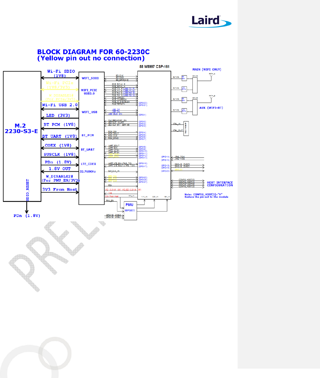
7. B
LOCK
D
IAGRAM
Figure 1: 60-2230C
60-2230C
Datasheet
Embedded Wireless Solutions Support Center:
http://ews-support.lairdtech.com
www.lairdtech.com/wireless
18
© Copyright 2017 Laird. All Rights Reserved
Americas: +1-800-492-2320
Europe: +44-1628-858-940
Hong Kong: +852 2923 0610
8. E
LECTRICAL
C
HARACTERISTICS
8.1 Absolute Maximum Ratings
Table 5 summarizes the absolute maximum ratings and Table 6 lists the recommended operating conditions for
the 60-2230C. Absolute maximum ratings are those values beyond which damage to the device can occur.
Functional operation under these conditions, or at any other condition beyond those indicated in the
operational sections of this document, is not recommended.
Note: Maximum rating for signals follows the supply domain of the signals.
Table 5: Absolute maximum ratings
Symbol (Domain) Parameter Max Rating Unit
VIO_SD WLAN host SDIO interface I/O supply (1.8V system)
2.2 V
VIO I/O configuration power supply (1.8V system) 2.2 V
3V3 External 3.3V power supply 4.0 V
Storage Storage Temperature -40 to +85 °C
ANT0; ANT1 Maximum RF input (reference to 50-Ω input) +10 dBm
ESD Electrostatic discharge tolerance 2000 V
8.2 Recommended Operating Conditions
Table 6: Recommended Operating Conditions
Symbol (Domain) Parameter Min Typ Max Unit
VIO_SD WLAN host interface I/O supply 1.62 1.8 1.98 V
VIO WLAN and BT GPIO I/O power supply 1.62 1.8 1.98 V
3V3 External 3.3V power supply 2.97 3.30 3.63 V
T-ambient Ambient temperature -30 25 85 °C
8.3 DC Electrical Characteristics
Table 7 list the general DC electrical characteristics over recommended operating conditions (unless otherwise
specified).
Table 7: General DC electrical characteristics (For 1.8V operation VIO_SD;VIO)
Symbol Parameter Conditions Min Typ Max Unit
VIH High Level Input Voltage -- 0.7 x 1V8
1V8+0.4 V
VIL Low Level Input Voltage -- -0.4 0.3 x 1V8
V
VHYS Input Hysteresis -- 100 mV
VOH Output high Voltage -- 1V8-0.4 V
VOL Output low Voltage -- 0.4 V
60-2230C
Datasheet
Embedded Wireless Solutions Support Center:
http://ews-support.lairdtech.com
www.lairdtech.com/wireless
19
© Copyright 2017 Laird. All Rights Reserved
Americas: +1-800-492-2320
Europe: +44-1628-858-940
Hong Kong: +852 2923 0610
8.4 WLAN Radio Receiver Characteristics
Table 8 and Table 9 summarize the WLAN 60-2230C receiver characteristics.
Table 8: WLAN receiver characteristics for 2.4 GHz signal chain operation
Symbol Parameter Conditions Min Typ Max Unit
Frx Receive input frequency range
2.412
2.484 GHz
Srf
Sensitivity
CCK, 1 Mbps
See Note
3
-95
dBm
CCK, 11 Mbps -90
OFDM, 6 Mbps -91
OFDM, 54 Mbps -75
HT20, MCS0 -91
HT20, MCS7 -73
Radj Adjacent channel rejection
OFDM, 6 Mbps
See Note
4
TBD
dB
OFDM, 54 Mbps TBD
HT20, MCS0 TBD
HT20, MCS7 TBD
3
Performance data are measured under signal chain operation.
4
Performance data are measured under signal chain operation.
Table 9: WLAN receiver characteristics for 5 GHz dual chain operation
Symbol Parameter Conditions Min
Typ Max Unit
Frx Receive input frequency
range
5.15
5.825 GHz
Srf
Sensitivity
OFDM, 6 Mbps
See Note
5
-89
dBm
OFDM, 54 Mbps -74
HT20, MCS0 -89
HT20, MCS7 -70
HT40, MCS0 -86
HT40, MCS7 -69
Radj Adjacent channel rejection
OFDM, 6 Mbps
See Note
6
TBD
dB
OFDM, 54 Mbps TBD
HT20, MCS0 TBD
HT20, MCS7 TBD
5
Performance data are measured under signal chain operation
6
Performance data are measured under signal chain operation.
60-2230C
Datasheet
Embedded Wireless Solutions Support Center:
http://ews-support.lairdtech.com
www.lairdtech.com/wireless
20
© Copyright 2017 Laird. All Rights Reserved
Americas: +1-800-492-2320
Europe: +44-1628-858-940
Hong Kong: +852 2923 0610
8.5 WLAN Transmitter Characteristics
Table 10: WLAN transmitter characteristics for 2.4 GHz per chain operation
Symbol Parameter Conditions Min Typ Max Unit
Ftx Transmit output frequency range 2.412 2.484 GHz
Pout Output power See Note
7
11b mask compliant 1-11Mbps 18
dBm
11g mask compliant 6-36Mbps 18
11g EVM compliant 48-54Mbps 16
11n HT20 mask compliant MCS0-5/MCS8-13 18
11n HT20 EVM compliant MCS6-7/MCS14-15
16
11n HT40 mask compliant MCS0-5/MCS8-13 16
11n HT40 EVM compliant MCS6-7/MCS14-15
14
ATx Transmit power accuracy at 25 - - + 2.0
dB
Freq. Mode/Rate (Mbps)
Output Power Per
Chain (dBm)
Typical Current
Consumption Single
Chain (mA)
8
Max. Current
Consumption Single
Chain (mA)
8
2412 MHz
1 Mbps 18dBm 340 620
54 Mbps 16dBm 280 500
HT20 MCS7 16dBm 280 510
2442 MHz
1 Mbps 18dBm 340 620
54 Mbps 16dBm 280 500
HT20 MCS7 16dBm 280 510
2472 MHz
1 Mbps 18dBm 340 620
54 Mbps 16dBm 280 500
HT20 MCS7 16dBm 280 510
Table 11: WLAN transmitter characteristics for 5 GHz per chain operation
Symbol Parameter Conditions Min Typ Max Unit
Ftx Transmit output frequency range 5.15 5.925
GHz
Pout Output power See Note
3
11a mask compliant 6-36Mbps 18
dBm
11a EVM compliant 48-54Mbps 16
11n HT20 mask compliant MCS0-5/MCS8-13 18
11n HT20 EVM compliant MCS6-7/MCS14-15
16
11n HT40 mask compliant MCS0-5/MCS8-13 16
11n HT40 EVM compliant MCS6-7/MCS14-15
16
11ac HT20 mask compliant MCS0-6 (
Ntst=1,2)
18
11ac HT20 EVM compliant MCS7-8(
Ntst=1,2)
16
11ac HT40 mask compliant MCS0-5 (
Ntst=1,2)
16
11ac HT40 EVM compliant MCS6-9(
Ntst=1,2)
14
11ac HT80 mask compliant MCS0-5 (
Ntst=1,2)
14
60-2230C
Datasheet
Embedded Wireless Solutions Support Center:
http://ews-support.lairdtech.com
www.lairdtech.com/wireless
21
© Copyright 2017 Laird. All Rights Reserved
Americas: +1-800-492-2320
Europe: +44-1628-858-940
Hong Kong: +852 2923 0610
Symbol Parameter Conditions Min Typ Max Unit
11ac HT80 EVM compliant MCS6-8(
Ntst=1,2)
12
11ac HT80 EVM compliant MCS9(
Ntst=1,2)
10
ATx Transmit power accuracy at 25 - - + 2.0 dB
Freq. Mode/Rate
[Mbps]
Output Power Per
Chain [dBm]
Typical Current
Consumption Single
Chain (mA)
8
Max. Current
Consumption Single
Chain (mA)
8
5180 MHz
5190 MHz
6 Mbps 18 dBm 400 710
54 Mbps 16 dBm 330 610
HT20 MCS0 18 dBm 400 720
HT20 MCS7 16 dBm 360 620
HT40 MCS7 14 dBm 320 550
5500 MHz
5510 MHz
6 Mbps 18 dBm 380 680
54 Mbps 16 dBm 330 600
HT20 MCS0 18 dBm 370 690
HT20 MCS7 16 dBm 320 600
HT40 MCS7 14 dBm 300 530
5825 MHz
5795 MHz
6 Mbps 18 dBm 380 690
54 Mbps 16 dBm 310 600
HT20 MCS0 18 dBm 360 710
HT20 MCS7 16 dBm 340 550
HT40 MCS7 14 dBm 300 530
7
Performance data are measured under
single
chain operation.
Note: Final TX power values on each channel are limited by the regulatory certification test limit.
60-2230C
Datasheet
Embedded Wireless Solutions Support Center:
http://ews-support.lairdtech.com
www.lairdtech.com/wireless
22
© Copyright 2017 Laird. All Rights Reserved
Americas: +1-800-492-2320
Europe: +44-1628-858-940
Hong Kong: +852 2923 0610
9. B
LUETOOTH
R
ADIO
C
HARACTERISTICS
Table 11 through Table 14 describe the basic rate transmitter performance, enhanced data transmitter
performance, basic rate receiver performance, enhanced rate receiver performance, and current consumption
conditions at 25°C.
Table 11: Basic rate transmitter performance temperature at 25°C (1.8V)
Test Parameter Min Typ Max BT Spec. Unit
Maximum RF Output Power 8 10 11 0 ~ +20 dBm
Frequency Range 2.4 — 2.4835
2.4 ≤ f ≤ 2.4835 GHz
20 dB Bandwidth — 919.5 — ≤ 1000 KHz
Δf1avg Maximum Modulation 140 165 175 140 < Δf1avg <
175 KHz
Δf2max Minimum Modulation — 135 — ≥ 115 KHz
Δf2avg/Δf1avg — 0.9 — ≥ 0.80 —
Initial Carrier Frequency — +/-5 — ≤±75 KHz
Drift Rate (DH1 package) — 4 — ≤ 20 KHz/50 µs
Drift (DH3 packet) — 8 — ≤25 KHz
Drift (DH5 packet) — 7 — ≤ 40 KHz
Adjacent Channel Power
F≥ ± 3MHz — –50 — < –40 dBm
F = ± 2MHz — -46 — ≤ –20 dBm
F = ± 1MHz — -15 — N/A dBm
Table 12: Enhanced data rate transmitter performance 25°C (1.8V)
Test Parameter Min Typ Max BT Spec. Unit
Relative Transmit Power 5 7 9 dBm
Max Carrier Frequency
Stability |wo|
2-DH5 — 1 — ≤ ±10 KHz
3-DH5 — 1 —
Max Carrier Frequency
Stability |wi|
2-DH5 — 4 — ≤ ±75 KHz
3-DH5 — 4 —
Max Carrier Frequency
Stability |w0+wi|
2-DH5 — 5 — ≤ ±75 KHz
3-DH5 — 5 —
RMS DEVM 2-DH5 — 4 — ≤ 20 %
3-DH5 — 4 — ≤13 %
Peak DEVM 2-DH5 — 9 — ≤ 35 %
3-DH5 — 9 — ≤ 25 %
99% DEVM 2-DH5 — 12 — ≤ 30 %
3-DH5 — 12 — ≤ 20 %
EDR Differential Phase Encoding — 99 — ≥ 99 %
Adjacent Channel Power F≥ ± 3MHz — TBD — < –40 dBm
F = ± 2MHz — TBD — ≤ –20 dBm
60-2230C
Datasheet
Embedded Wireless Solutions Support Center:
http://ews-support.lairdtech.com
www.lairdtech.com/wireless
23
© Copyright 2017 Laird. All Rights Reserved
Americas: +1-800-492-2320
Europe: +44-1628-858-940
Hong Kong: +852 2923 0610
Table 13: Basic rate receiver performance at 1.8V
Test Parameter Min Typ Max BT Spec. Unit
Sensitivity (1DH5) BER ≤ 0.1% — –95 -92 ≤ –70 dBm
Maximum Input BER ≤ 0.1% –20 -10 — ≥ –20 dBm
Carrier-to-Interferer Ratio
(C/I)
Co-Channel — 10 11 11
C/I (± 1 MHz) — -4 0 0 dB
C/I (± 2 MHz) — -45 — –30 dB
C/I (± 3 MHz) — -49 — –40 dB
Maximum Level of Intermodulation Interferers
–39 -30 - ≥ –39 dBm
Table 14: Enhanced data rate receiver performance 1.8V
Test Parameter Min Typ Max Bluetooth
Specification Unit
Sensitivity (BER ≤0.01%)
π/4 DQPSK — -94 -91 ≤ –70 dBm
8 DPSK — -88 -85 ≤ –70 dBm
Maximum Input (BER ≤0.1%) π/4 DQPSK –20 — — ≥ –20 dBm
8 DPSK –20 — — ≥ –20 dBm
Co-Channel C/I (BER ≤0.1%) π/4 DQPSK — 10 13 ≤ ±13 dB
8 DPSK — 16 20 ≤ ±20 dB
Adjacent Channel C/I (1 MHz) π/4 DQPSK — -9 0 ≤ 0 dB
8 DPSK — -6 5 ≤5 dB
Second Adjacent Channel C/I
(2 MHz)
π/4 DQPSK — -47 –30 ≤ –30 dB
8 DPSK — -42 –25 ≤ –25 dB
Third Adjacent Channel C/I
(3 MHz)
π/4 DQPSK — -51 –40 ≤ –40 dB
8 DPSK — -48 –33 ≤ –33 dB
Out-of-band blocking
30-2000MHz
— -12.5 — — dBm
2-2.399GHz
— -12.4 — — dBm
2.484-3GHz
— -18 — — dBm
3-12.75GHz
— -2.6 — — dBm

60-2230C
Datasheet
Embedded Wireless Solutions Support Center:
http://ews-support.lairdtech.com
www.lairdtech.com/wireless
24
© Copyright 2017 Laird. All Rights Reserved
Americas: +1-800-492-2320
Europe: +44-1628-858-940
Hong Kong: +852 2923 0610
10. SDIO
T
IMING
R
EQUIREMENTS
The 60-2230C SDIO host interface pins are powered from the VIO_SD voltage supply. The SDIO electrical
specifications are identical for the 1-bit SDIO and 4-bit SDIO modes.
10.1
SDR12, SDR25, SDR50 Mode (up to 100MHz) (1.8V)
Figure 2:SDIO protocol timing Diagram--- SDR12, SDR25, SDR50 modes (up to 100 MHz) (1.8V)
Table 16: SDIO timing requirements--- SDR12, SDR25, SDR50 modes (up to 100 MHz) (1.8V)
Note: Over full range of values specified in the Recommended Operating Conditions unless otherwise
specified.
Symbol Parameter Condition Min. Typ. Max. Unit
f
PP
Clock Frequency SDR12/25/50 25 - 100 MHz
T
ISU
Input setup time SDR12/25/50 3 -- - ns
T
IH
Input Hold time SDR12/25/50 0.8 - - ns
T
CLK
Clock Time SDR12/25/50 10 - 40 ns
T
CR
,T
CF
Raise time, Fall time
T
CR
,T
CF
<2ns (max) at 100 MHz
C
CARD
=10pF
SDR12/25/50 - - 0.2*T
CLK
ns
T
ODLY
Output delay time
C
L
30pF SDR12/25/50 - - 7.5 ns
T
OH
Output hold time
C
L
=15pF SDR12/25/50 1.5 - - ns
60-2230C
Datasheet
Embedded Wireless Solutions Support Center:
http://ews-support.lairdtech.com
www.lairdtech.com/wireless
25
© Copyright 2017 Laird. All Rights Reserved
Americas: +1-800-492-2320
Europe: +44-1628-858-940
Hong Kong: +852 2923 0610
10.2 SDR104 Mode (208MHz) (1.8V)
Figure 3: SDIO protocol timing Diagram--- SDR104 modes (up to 208 MHz) (1.8V)
Table 17: SDIO timing requirements--- SDR104 modes (up to 208MHz) (1.8V)
Note: Over full range of values specified in the Recommended Operating Conditions unless otherwise
specified.
Symbol Parameter Condition Min. Typ. Max. Unit
f
PP
Clock Frequency SDR104 0 - 208 MHz
T
ISU
Input setup time SDR104 1.4 -- - ns
T
IH
Input Hold time SDR104 0.8 - - ns
T
CLK
Clock Time SDR104 4.8 - - ns
T
CR
,T
CF
Raise time, Fall time
T
CR
,T
CF
<0.96ns (max) at 208 MHz
C
CARD
=10 pF
SDR104
- - 0.2*T
CLK
ns
T
OP
Card Output phase SDR104 0 - 10 ns
T
ODW
Output timing pf variable data
window SDR12/25/50
2.88 - - ns
60-2230C
Datasheet
Embedded Wireless Solutions Support Center:
http://ews-support.lairdtech.com
www.lairdtech.com/wireless
26
© Copyright 2017 Laird. All Rights Reserved
Americas: +1-800-492-2320
Europe: +44-1628-858-940
Hong Kong: +852 2923 0610
10.3 DDR50 Mode (50MHz) (1.8V)
Figure 4: SDIO CMD timing Diagram--- DDR50 modes (50 MHz) (1.8V)
Figure 5: SDIO DAT[3:0] timing Diagram--- DDR50 modes (50 MHz) (1.8V)
Note: In DDR50 mode, DAT[3:0] lines are samples on both edges pF the clock (not applicable for CMD line)
Table 18: SDIO timing requirements--- DDR50 modes (50MHz)
Symbol Parameter Condition Min. Typ. Max. Unit
Clock
T
CLK
Clock time
50MHz (max) between rising edge DDR50 20 -- -- ns
T
CR
, T
CF
Rise time, fall time
T
CR
, T
CF
<4.00ns (max) at 50MHz.
C
CARD
=10pF
DDR50 -- -- 0.2*T
CLK
ns
Clock Duty -- DDR50 45 -- 55 %
CMD Input (referenced to clock rising edge)
T
IS
Input setup time DDR50 6 -- -- ns
60-2230C
Datasheet
Embedded Wireless Solutions Support Center:
http://ews-support.lairdtech.com
www.lairdtech.com/wireless
27
© Copyright 2017 Laird. All Rights Reserved
Americas: +1-800-492-2320
Europe: +44-1628-858-940
Hong Kong: +852 2923 0610
Symbol Parameter Condition Min. Typ. Max. Unit
C
CARD
T
IH
Input hold time
C
CARD
DDR50 0.8 -- -- ns
CMD Output (referenced to clock rising and failing edge)
T
ODLY
Output delay time during data transfer
mode
C
L
30pF (1card)
DDR50 -- -- 13.7 ns
T
OHLD
Output hold time
C
L
≥15pF (1 card) DDR50 1.5 -- -- ns
DAT[3:0] Input (referenced to clock rising and failing edges)
T
IS2X
Input setup time
C
CARD
DDR50 3 -- -- ns
T
IH2X
Input hold time
C
CARD
DDR50 0.8 -- -- ns
DAT[3:0] Output (referenced to clock rising and failing edges)
T
ODLY2X (max)
Output delay time during data transfer
mode
C
L
25pF (1card)
DDR50 -- -- 7.0 ns
T
ODLY2X (min)
Output hold time
C
L
≥15pF (1 card)) DDR50 1.5 -- -- ns
11.
USB
S
PECIFICATIONS
11.1 USB LS Driver and Receiver Parameters
Table 19:
Notes: Over full range of values specified in the Recommended Operating Conditions unless otherwise
specified.
The load is 100Ω differential for these parameters, unless other specified.
Table 15: USB LS Driver and Receiver Specifications
Symbol Parameter Min. Typ.
Max. Unit
BR Baud rate - 1.5 - Mbps
BR
PPM
Baud rate tolerance -15000
- 15000
ppm
Driver Specifications
V
OH
Output signal ended high
Defined with 1.425KΩ pull-up resistor to 3.6V 2.8 - 3.6 V
V
OL
Output signal ended low
Defined with 1.425KΩ pull-up resistor to ground 0.0 - 0.3 V
V
CRS
Output signal crossover voltage 1.3 2.0 V
60-2230C
Datasheet
Embedded Wireless Solutions Support Center:
http://ews-support.lairdtech.com
www.lairdtech.com/wireless
28
© Copyright 2017 Laird. All Rights Reserved
Americas: +1-800-492-2320
Europe: +44-1628-858-940
Hong Kong: +852 2923 0610
Symbol Parameter Min. Typ.
Max. Unit
T
LR
Data fall time
Defined from 10% to 90% for raise time and 90% to 10%
for fall time
75.0 - 300.0
ns
T
LF
Data risel time
Defined from 10% to 90% for raise time and 90% to 10%
for fall time
75.0 - 300.0
ns
T
LRFM
Rise and fall time matching 80.0 - 125.0
%
T
UDJ1
Source jitter total: to next transition
*Including frequency tolerance. Timing difference
between the differential data signals.
*Defined at crossover point of differential signals
-95
-
95
ns
T
UDJ2
Source jitter total: for paired transitions
*Including frequency tolerance. Timing difference
between the differential data signals.
*Defined at crossover point of differential signals
-150
-
150
ns
Receiver Specifications
V
IH
Input signal ended high 2.0 - - V
V
IL
Input signal ended low - - 0.8 V
V
DI
Differential input sensitivity 0.2 - - V
60-2230C
Datasheet
Embedded Wireless Solutions Support Center:
http://ews-support.lairdtech.com
www.lairdtech.com/wireless
29
© Copyright 2017 Laird. All Rights Reserved
Americas: +1-800-492-2320
Europe: +44-1628-858-940
Hong Kong: +852 2923 0610
11.2 USB FS Driver and Receiver Parameters
Notes: Over full range of values specified in the Recommended Operating Conditions unless otherwise
specified.
The load is 100Ω differential for these parameters, unless other specified.
Table 16: USB FS Driver and Receiver Specifications
Symbol Parameter Min. Typ.
Max. Unit
BR Baud rate - 12.0
- Mbps
BR
PPM
Baud rate tolerance -2500 - 2500 ppm
Driver Specifications
V
OH
Output signal ended high
Defined with 1.425KΩ pull-up resistor to 3.6V 2.8 - 3.6 V
V
OL
Output signal ended low
Defined with 1.425KΩ pull-up resistor to ground 0.0 - 0.3 V
V
CRS
Output signal crossover voltage 1.3 2.0 V
T
FR
Output raise time
Defined from 10% to 90% for raise time and 90% to 10%
for fall time
-4.0 - 20.0 ns
T
FL
Output fall time
Defined from 10% to 90% for raise time and 90% to 10%
for fall time
-4.0 - 20.0 ns
T
DJ1
Source jitter total: to next transition
*Including frequency tolerance. Timing difference
between the differential data signals.
*Defined at crossover point of differential signals
-3.5
-
3.5
ns
T
DJ2
Source jitter total: for paired transitions
*Including frequency tolerance. Timing difference
between the differential data signals.
*Defined at crossover point of differential signals
-4.0
-
4.0
ns
T
FDEOP
Source jitter for differential transition to SE0 transition.
Defined at crossover point of differential signals
-2.0
-
5.0
ns
Receiver Specifications
V
IH
Input signal ended high 2.0 - - V
V
IL
Input signal ended low - - 0.8 V
V
DI
Differential input sensitivity 0.2 - - V
T
JR1
Receiver jitter: to next transition
Defined at crossover point of differential data signals
-18.5 - 18.5 ns
T
JR2
Receiver jitter: for paired transitions
Defined at crossover point of differential data signals
-9.0 - 9.0 ns
60-2230C
Datasheet
Embedded Wireless Solutions Support Center:
http://ews-support.lairdtech.com
www.lairdtech.com/wireless
30
© Copyright 2017 Laird. All Rights Reserved
Americas: +1-800-492-2320
Europe: +44-1628-858-940
Hong Kong: +852 2923 0610
11.3 USB HS Driver and Receiver Parameters
Notes: Over full range of values specified in the Recommended Operating Conditions unless otherwise
specified.
The load is 100Ω differential for these parameters, unless other specified.
Table 17: USB HS Driver and Receiver Specifications
Symbol Parameter Min. Typ.
Max. Unit
BR Baud rate - 480 - Mbps
BR
PPM
Baud rate tolerance -500 - 500 ppm
Driver Specifications
V
HSOH
Data signal high 360 - 440 mV
V
HSOL
Data signal low -10 - 10 mV
T
HSR
Data rise time
Defined from 10% to 90% for raise time and 90% to 10%
for fall time
500 - - ns
T
HSF
Data fall time
Defined from 10% to 90% for raise time and 90% to 10%
for fall time
-500 - - ns
Receiver Specifications
V
HSCM
Input signal ended low -50 - 500 mV
60-2230C
Datasheet
Embedded Wireless Solutions Support Center:
http://ews-support.lairdtech.com
www.lairdtech.com/wireless
31
© Copyright 2017 Laird. All Rights Reserved
Americas: +1-800-492-2320
Europe: +44-1628-858-940
Hong Kong: +852 2923 0610
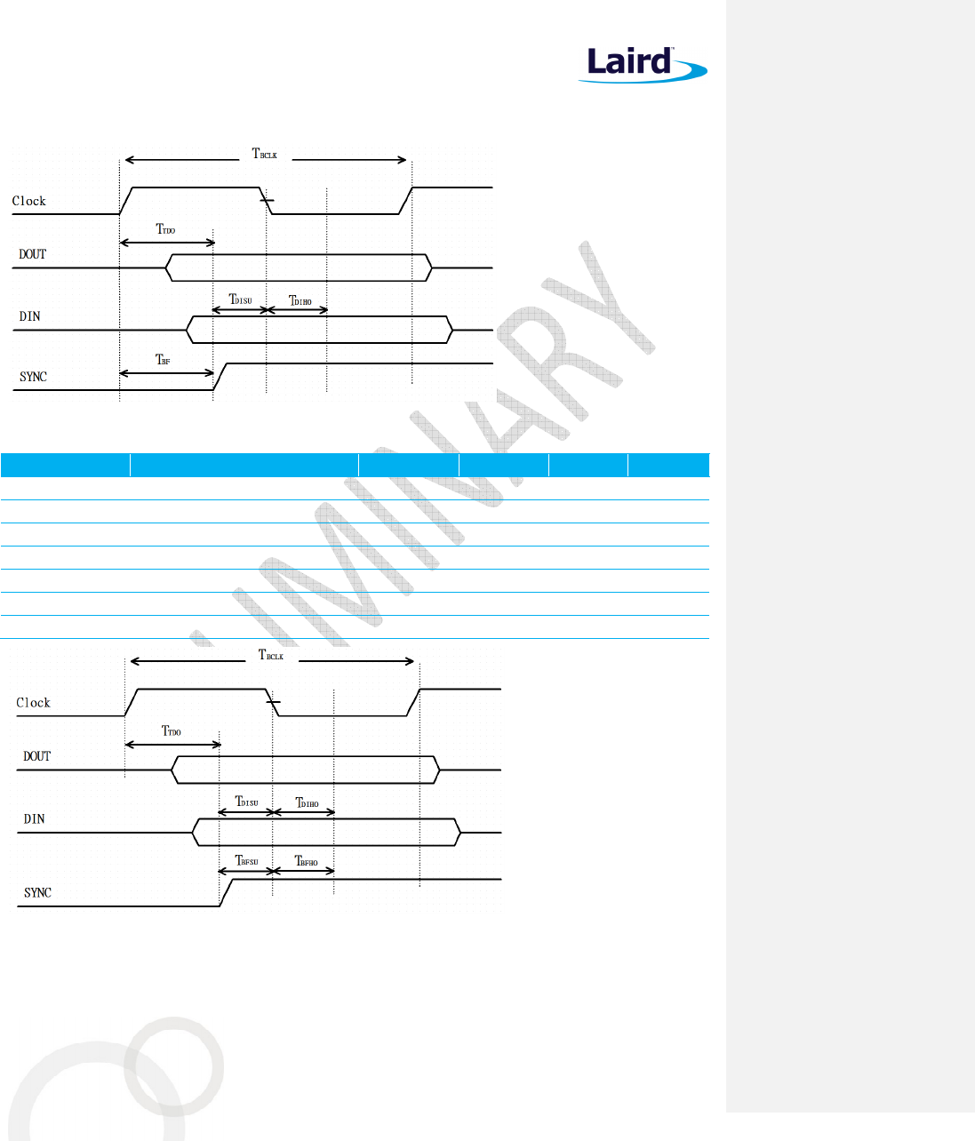
12. PCM
INTERFACE SPECIFICATIONS
Figure 6: PCM Timing Specification – Master Mode
Table 18:PCM Timing Specification – Master Mode
Symbol Parameter Min. Typ. Max. Unit
F
BCLK
- - 2/2.048 - MHz
Duty Cycle
BCLK
- 0.4 0.5 0.6 -
T
BCLK rise/fall
- - 3 - ns
T
DO
- - - 15 ns
T
DISU
- 20 - - ns
T
DIHO
- 15 - - ns
T
BF
- - - 15 ns
Figure 7: PCM Timing Specification – Slave Mode
60-2230C
Datasheet
Embedded Wireless Solutions Support Center:
http://ews-support.lairdtech.com
www.lairdtech.com/wireless
32
© Copyright 2017 Laird. All Rights Reserved
Americas: +1-800-492-2320
Europe: +44-1628-858-940
Hong Kong: +852 2923 0610
Table 19: PCM Timing Specification – Slave Mode
Symbol Parameter Min. Typ. Max. Unit
F
BCLK
- - 2/2.048 - MHz
Duty Cycle
BCLK
- 0.4 0.5 0.6 -
T
BCLK rise/fall
- - 3 - ns
T
DO
- - - 30 ns
T
DISU
- 15 - - ns
T
DIHO
- 10 - - ns
T
BFSU
- 15 - - ns
T
BFHO
- 10 - - ns
13. P
IN
D
EFINITIONS
Table 20: Pin definitions
Pin #
Name Type Voltage
Ref. Description If Not
Used
1 GND - - Ground GND
2 3.3V Power - 3.3V module power supply -
3 USB_D+ I/O 3.3V USB Differential Data-Positive N/C
4 3.3V Power - 3.3V module power supply -
5 USB_D- I/O 3.3V USB Differential Data-Negative N/C
6 LED1# O,PU 3.3V LED indicator for WLAN with 10mA drive capability
N/C
7 GND - - Ground GND
8 PCM_CLK I/O 1.8V
PCM Clock Signal (Optimal)
Optimal clock used for some codecs.
Output if Master mode; Input if Slave mode.
N/C
9 SDIO CLK I,PU 1.8V SDIO 4-bit Mode Clock Input N/C
10 PCM_SYNC I/O 1.8V PCM Sync Pulse Signal
Output if Master mode; Input if Slave mode. N/C
11 SDIO CMD I/O 1.8V SDIO 4-bit Mode Command/Response N/C
12 PCM_IN I 1.8V PCM Data N/C
13 SDIO DATA0 I/O,PU
1.8V SDIO 4-bit Mode DATA line Bit[0] N/C
14 PCM_OUT O 1.8V PCM Data N/C
15 SDIO DATA1 I/O,PU
1.8V SDIO 4-bit Mode DATA line Bit[1] N/C
16 LED2# O,PU 3.3V LED indicator for BT with 10mA drive capability. N/C
17 SDIO DATA2 I/O,PU
1.8V SDIO 4-bit Mode DATA line Bit[2] N/C
18 GND - - Ground GND
19 SDIO DATA3 I/O,PU
1.8V SDIO 4-bit Mode DATA line Bit[3] N/C
20 UART WAKE# N/C N/C N/C N/C
21 SDIO WAKE# N/C N/C N/C N/C
22 UART TXD O 1.8V UART Serial Data Output N/C
60-2230C
Datasheet
Embedded Wireless Solutions Support Center:
http://ews-support.lairdtech.com
www.lairdtech.com/wireless
33
© Copyright 2017 Laird. All Rights Reserved
Americas: +1-800-492-2320
Europe: +44-1628-858-940
Hong Kong: +852 2923 0610
Pin #
Name Type Voltage
Ref. Description If Not
Used
23 SDIO RESET# N/C N/C N/C N/C
32 UART RXD I 1.8V UART Serial Data Input N/C
33 GND - - Ground GND
34 UART RTS O,WPU
1.8V UART Request To Send (Active low) N/C
35 PERp0 I 1.8V PCIe Receive Data-Positive N/C
36 UART CTS I, PU 1.8V UART Clear To Send (Active low) N/C
37 PERn0 I 1.8V PCIe Receive Data-Negative N/C
38 VENDOR
DEFINED38 N/C N/C N/C N/C
39 GND - - Ground GND
40 VENDOR
DEFINED40 N/C N/C N/C N/C
41 PETp0 O 1.8V PCIe Transmit Data-Positive N/C
42 VENDOR
DEFINED42 N/C N/C N/C N/C
43 PETn0 O 1.8V PCIe Transmit Data-Negative N/C
44 COEX3 I/O 1.8V General purpose I/O pin. N/C
45 GND - - Ground GND
46 COEX2 O,PD 1.8V Serial data to external LTE device/ N/C
47 REFCLKp0 I 1.8V PCIe Differential Clock input-Positive N/C
48 COEX1 I,PD 1.8V Serial data from external LTE device/ N/C
49 REFCLKn0 I 1.8V PCIe Differential Clock input-Negative N/C
50 SUSCLK(32KHz) I,PU 3.3V
Sleep Clock Input
An external sleep clock of 32.768KHz with
minimum +/-250ppm is required for power saving
mode
-
51 GND - - Ground GND
52 PERST0# I,PD 3.3V PCIe host indication to reset the device (input)
(active low) N/C
53 CLKREQ0# I/O 3.3V PCIe clock request (input/output) (active low) GND
54 W_DISABLE2# I 3.3V
Enable input for all Regulators inside the 60-SIPT.
Note: DO NOT float this pin. Pull-up to 3.3V with
100K for normal operation.
100K,
PU
55 PEWAKE0# I/O 3.3V PCIe wake signal (input/output) (active low) N/C
56 W_DISABLE1#
(O)(0/3.3V) I,PU 3.3V PCIe host indication to disable the WLAN function
of the device (input) (active low) N/C
57 GND - - Ground GND
58 I2C DATA
(I/O)(0/3.3V) N/C N/C N/C N/C
59 RESERVED/PETp1
N/C N/C N/C N/C
60 I2C CLK
(O)(0/3.3V) N/C N/C N/C N/C
60-2230C
Datasheet
Embedded Wireless Solutions Support Center:
http://ews-support.lairdtech.com
www.lairdtech.com/wireless
34
© Copyright 2017 Laird. All Rights Reserved
Americas: +1-800-492-2320
Europe: +44-1628-858-940
Hong Kong: +852 2923 0610
Pin #
Name Type Voltage
Ref. Description If Not
Used
61 RESERVED/PETn1
N/C N/C N/C N/C
62 ALERT#
(I)(0/3.3V) N/C N/C N/C N/C
63 GND - - Ground GND
64 RESERVED N/C N/C N/C N/C
65 RESERVED/PERp1
N/C N/C N/C N/C
66 UIM_SWP/PERST
1# N/C N/C N/C N/C
67 RESERVED/PERn1
N/C N/C N/C N/C
68 UIM_POWER_SN
K/CLKREQ1# N/C N/C N/C N/C
69 GND - - Ground GND
70
UIM_POWER_SRC
/GPIO1/PEWAKE1
#
N/C N/C N/C N/C
71 RESERVED/REFCL
Kp1 N/C N/C N/C N/C
72 3.3V Power - 3.3V module power supply -
73 RESERVED/REFCL
Kn1 N/C N/C N/C N/C
74 3.3V Power - 3.3V module power supply -
75 GND - - Ground GND
76 GND - - Ground GND
77 GND - - Ground GND
60-2230C
Datasheet
Embedded Wireless Solutions Support Center:
http://ews-support.lairdtech.com
www.lairdtech.com/wireless
35
© Copyright 2017 Laird. All Rights Reserved
Americas: +1-800-492-2320
Europe: +44-1628-858-940
Hong Kong: +852 2923 0610
14. M
ECHANICAL
S
PECIFICATIONS
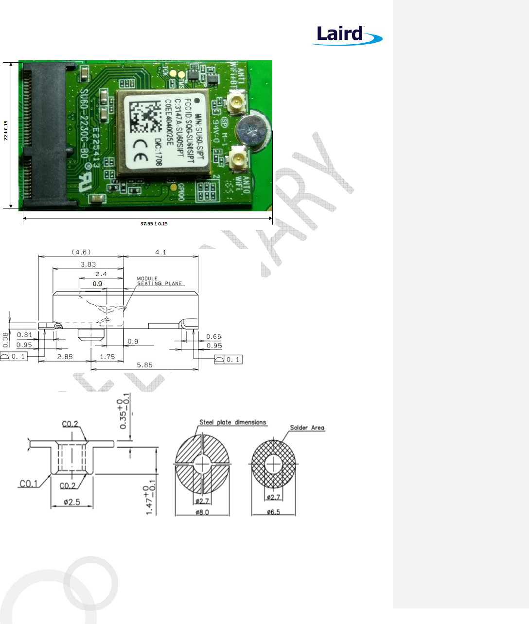
Module dimensions of 60-2230C are 22mm x 30mm x 3.3mm. Detail drawings are shown in Error! Reference
source not found..
Figure 8: Module dimension of 60-2230C
Note: The Wi-Fi MAC address is located on the product label. The BT MAC address is always numerically
subsequent to the Wi-Fi MAC address. Therefore, the BT MAC address is the Wi-Fi MAC address
plus one.
15. MOUNTING
The 60-2230C connects to the host via a standard PCI EXPRESS M2 connector. The Kyocera’s (www.Kyocera-
connector.com) 6411 series provide 1.8 mm, 2.3 mm and 3.2 mm connector heights.
Because the 60-2230C is a single-side component module, we recommend the following part number (which has
a 2.3 mm connector height): 24-6411-067-101-897E
The stand-off mating to the recommend 2.3 mm connector from EMI STOP (www.EMISTOP.com) is part number
F50M16-041525P1D4M. Detail layout and stencil opening are show in Figure 9.
60-2230C
Datasheet
Embedded Wireless Solutions Support Center:
http://ews-support.lairdtech.com
www.lairdtech.com/wireless
36
© Copyright 2017 Laird. All Rights Reserved
Americas: +1-800-492-2320
Europe: +44-1628-858-940
Hong Kong: +852 2923 0610
Figure 9: Mounting information of the 60-2230C and recommended layout pattern for the stand-off
60-2230C
Datasheet
Embedded Wireless Solutions Support Center:
http://ews-support.lairdtech.com
www.lairdtech.com/wireless
37
© Copyright 2017 Laird. All Rights Reserved
Americas: +1-800-492-2320
Europe: +44-1628-858-940
Hong Kong: +852 2923 0610
16. RF
L
AYOUT
D
ESIGN
G
UIDELINES
/
P
RECAUTIONS
The following is a list of RF layout design guidelines and recommendation when installing a Laird radio into your
device.
Do not run antenna cables directly above or directly below the radio.
Do not place any parts or run any high speed digital lines below the radio.
If there are other radios or transmitters located on the device (such as a Bluetooth radio), place the
devices as far apart from each other as possible. Also, make sure there is at least 25 dB isolation between
the Bluetooth antenna and the Wi-Fi antenna.
Ensure that there is the maximum allowable spacing separating the antenna connectors on the Laird radio
from the antenna. In addition, do not place antennas directly above or directly below the radio.
Laird recommends the use of a double-shielded cable for the connection between the radio and the
antenna elements.
Be sure to put the capacitor on the power pin as close as possible to reduce the radiation issue.
Use proper electro-static-discharge (ESD) procedures when installing the Laird radio module.
To get maximum throughput when operate at MIMO 2x2, two antennas with at least 25 dB isolation are
recommended.
To avoid negatively impacting Tx power and receiver sensitivity, do not cover the antennas with metallic
objects or components.
Opening/handing/removing must be done on an anti-ESD treated workbench. All workers must be also
have undergone anti-ESD treatment.
The devices should be mounted within one year of the date of delivery.
17. R
EGULATORY
17.1 Certified Antennas
Model Type Connector
2400~2483.5MHz
5150~5250MHz 5250~5350MHz
5470~5725MHz 5725~5850MHz
Laird MAF94051 Dipole RP-SMA 2.1 dBi (2.4-2.5 GHz), 2.4 dBi (4.9 GHz)
2.6 dBi (5.25 GHz), 3.4 dBi (5.875 GHz)
Laird/NanoBlade-IP04 PCB
Dipole IPEX MHF
2 dBi (2.4-2.5 GHz),
3.9 dBi (5.15-5.35 GHz), 4 dBi (5.6 GHz)
Laird/MAF95310 Mini Nano Blade
Flex
PCB
Dipole IPEX MHF
2.79 dBi (2.4 GHz), 3.38 dBi (5 GHz)
Laird/NanoBlue-IP04 PCB
Dipole IPEX MHF
2 dBi (2.4 GHz only)
Ethertronics/WLAN_1000146
Isolated
Magnetic
Dipole
IPEX MHF
2.5 dBi (2.390-2.490 GHz),
3.5 dBi (4.900-5.100, 5.150-5.350,
5.70-5.900 GHz)
60-2230C
Datasheet
Embedded Wireless Solutions Support Center:
http://ews-support.lairdtech.com
www.lairdtech.com/wireless
38
© Copyright 2017 Laird. All Rights Reserved
Americas: +1-800-492-2320
Europe: +44-1628-858-940
Hong Kong: +852 2923 0610
18. FCC
AND
IC
R
EGULATORY
Model
US/FCC
CANADA/IC
60
-
2230C
SQG
-
60
2230C
3147A
-
60
2230C
The 60-2230C has been designed to pass certification with the antenna listed below. The required antenna
impedance is 50 ohms.
Table 21: FCC antenna information
Model
Type
Connector
Peak gain ( dBi )
2400~2483.5
MHz
5150~5250
MHz
5250~5350
MHz
5470~5725
MHz
5725~5850
MHz
Laird
MAF94051 Dipole RP-SMA 2.1 dBi 2.4 dBi 2.6 dBi 3.4 dBi
Laird
NanoBlade-IP04 PCB Dipole
IPEX MHF 2 dBi 3.9 dBi 4 dBi
Laird
MAF95310 Mini
NanoBlade Flex
PCB Dipole
IPEX MHF 2.79 dBi 3.38 dBi
Laird
NanoBlue-IP04 PCB Dipole
IPEX MHF 2dBi _
Ethertronics
WLAN_1000146
Isolated
Magnetic
Dipole
IPEX MHF 2.5dBi 4.5 dBi
18.1 FCC
18.1.1 Federal Communication Commission Interference Statement
This equipment has been tested and found to comply with the limits for a Class B digital device, pursuant to Part
15 of the FCC Rules. These limits are designed to provide reasonable protection against harmful interference in a
residential installation. This equipment generates, uses and can radiate radio frequency energy and, if not
installed and used in accordance with the instructions, may cause harmful interference to radio communications.
However, there is no guarantee that interference will not occur in a particular installation. If this equipment
does cause harmful interference to radio or television reception, which can be determined by turning the
equipment off and on, the user is encouraged to try to correct the interference by one of the following
measures:
Reorient or relocate the receiving antenna.
Increase the separation between the equipment and receiver.
Connect the equipment into an outlet on a circuit different from that to which the receiver is connected.
Consult the dealer or an experienced radio/TV technician for help.
18.1.2 FCC Caution
Any changes or modifications not expressly approved by the party responsible for compliance could void the
user's authority to operate this equipment.

60-2230C
Datasheet
Embedded Wireless Solutions Support Center:
http://ews-support.lairdtech.com
www.lairdtech.com/wireless
39
© Copyright 2017 Laird. All Rights Reserved
Americas: +1-800-492-2320
Europe: +44-1628-858-940
Hong Kong: +852 2923 0610
This device complies with Part 15 of the FCC Rules. Operation is subject to the following two conditions: (1) This
device may not cause harmful interference, and (2) this device must accept any interference received, including
interference that may cause undesired operation.
18.1.3 Important Note
Radiation Exposure Statement
This equipment complies with FCC radiation exposure limits set forth for an uncontrolled environment. This
equipment should be installed and operated with minimum distance 20cm between the radiator and your body.
This transmitter must not be co-located or operating in conjunction with any other antenna or transmitter.
Country Code selection feature to be disabled for products marketed to the US/Canada.
This device is intended only for OEM integrators under the following conditions:
1. The antenna must be installed such that 20 cm is maintained between the antenna and users, and
2. The transmitter module may not be co-located with any other transmitter or antenna,
3. For all products market in US, OEM has to limit the operation channels in CH1 to CH11 for 2.4G band
by supplied firmware programming tool. OEM shall not supply any tool or info to the end-user
regarding to Regulatory Domain change.
As long as the three conditions above are met, further transmitter testing will not be required. However, the
OEM integrator is still responsible for testing their end-product for any additional compliance requirements
required with this module installed.
Important Note
In the event that these conditions cannot be met (for example certain laptop configurations or co-location with
another transmitter), then the FCC authorization is no longer considered valid and the FCC ID cannot be used on
the final product. In these circumstances, the OEM integrator will be responsible for re-evaluating the end
product (including the transmitter) and obtaining a separate FCC authorization.
18.1.4 End Product Labeling
This transmitter module is authorized only for use in device where the antenna may be installed such that 20 cm
may be maintained between the antenna and users. The final end product must be labeled in a visible area with
the following: Contains FCC ID: SQG-602230C.
18.1.5 Manual Information to the End User
The OEM integrator has to be aware not to provide information to the end user regarding how to install or
remove this RF module in the user’s manual of the end product which integrates this module.
The end user manual shall include all required regulatory information/warning as show in this manual.
60-2230C
Datasheet
Embedded Wireless Solutions Support Center:
http://ews-support.lairdtech.com
www.lairdtech.com/wireless
40
© Copyright 2017 Laird. All Rights Reserved
Americas: +1-800-492-2320
Europe: +44-1628-858-940
Hong Kong: +852 2923 0610
18.2 Industry Canada
18.2.1 Industry Canada Statement
This device complies with Industry Canada’s license-exempt RSSs. Operation is subject to the following two
conditions:
This device may not cause interference; and
This device must accept any interference, including interference that may cause undesired operation of
the device.
Le présent appareil est conforme aux CNR d’Industrie Canada applicables aux appareils radio exempts de licence.
L’exploitation est autorisée aux deux conditions suivantes:
l’appareil ne doit pas produire de brouillage;
l’utilisateur de l’appareil doit accepter tout brouillage radioélectrique subi, même si le brouillage est
susceptible d’en compromettre le fonctionnement.
This radio transmitter (IC: 3147A-602230C) has been approved by Industry Canada to operate with the antenna
types listed below with the maximum permissible gain indicated. Antenna types not included in this list, having a
gain greater than the maximum gain indicated for that type, are strictly prohibited for use with this device.
Le présent émetteur radio (IC: 3147A-602230C) a été approuvé par Industrie Canada pour fonctionner avec les
types d'antenne énumérés ci-dessous et ayant un gain admissible maximal. Les types d'antenne non inclus dans
cette liste, et dont le gain est supérieur au gain maximal indiqué, sont strictement interdits pour l'exploitation de
l'émetteur.
18.2.2 Antenna Information
Table 22: Antenna information
Model
Type
Connector
Peak gain ( dBi )
2400~2483.5
MHz
5150~5250
MHz
5250~5350
MHz
5470~5725
MHz
5725~5850
MHz
Laird
MAF94051 Dipole RP-SMA 2.1 dBi 2.4 dBi 2.6 dBi 3.4 dBi
Laird
NanoBlade-IP04 PCB Dipole
IPEX MHF 2 dBi 3.9 dBi 4 dBi
Laird
MAF95310 Mini
NanoBlade Flex
PCB Dipole
IPEX MHF 2.79 dBi 3.38 dBi
Laird
NanoBlue-IP04 PCB Dipole
IPEX MHF 2dBi _
Ethertronics
WLAN_1000146
Isolated
Magnetic
Dipole
IPEX MHF 2.5dBi 3.5 dBi

60-2230C
Datasheet
Embedded Wireless Solutions Support Center:
http://ews-support.lairdtech.com
www.lairdtech.com/wireless
41
© Copyright 2017 Laird. All Rights Reserved
Americas: +1-800-492-2320
Europe: +44-1628-858-940
Hong Kong: +852 2923 0610
18.2.3 Caution:
(i) The device for operation in the band 5150–5250 MHz is only for indoor use to reduce the potential for
harmful interference to co-channel mobile satellite systems;
(ii) For devices with detachable antenna(s), the maximum antenna gain permitted for devices in the bands 5250-
5350 MHz and 5470-5725 MHz shall be such that the equipment still complies with EIRP limit;
(iii) For devices with detachable antenna(s), the maximum antenna gain permitted for devices in the band 5725-
5850 MHz shall be such that the equipment still complies with the EIRP limits specified for point-to-point and
non-point-to-point operation as appropriate; and
Operations in the 5.25-5.35GHz band are restricted to indoor usage only.
18.2.4 Avertissement:
(i) les dispositifs fonctionnant dans la bande de 5150 à 5250MHz sont réservés uniquement pour une utilisation
à l'intérieur afin de réduire les risques de brouillage préjudiciable aux systèmes de satellites mobiles utilisant les
mêmes canaux;
(ii) pour les dispositifs munis d'antennes amovibles, le gain maximal d'antenne permis pour les dispositifs
utilisant les bandes de 5250 à 5350MHz et de 5470 à 5725 MHz doit être conforme à la limite de la p.i.r.e;
(iii) pour les dispositifs munis d'antennes amovibles, le gain maximal d'antenne permis (pour les dispositifs
utilisant la bande de 5725 à 5850 MHz) doit être conforme à la limite de la p.i.r.e. spécifiée pour l'exploitation
point à point et l'exploitation non point à point, selon le cas;
Les opérations dans la bande de 5.25-5.35GHz sont limités à un usage intérieur seulement.
18.2.5 Radiation Exposure Statement
This equipment complies with Canada radiation exposure limits set forth for an uncontrolled environment. This
equipment should be installed and operated with minimum distance 20cm between the radiator and your body.
18.2.6 Déclaration d'exposition aux radiations
Cet équipement est conforme Canada limites d'exposition aux radiations dans un environnement non contrôlé.
Cet équipement doit être installé et utilisé à distance minimum de 20cm entre le radiateur et votre corps.
This device is intended only for OEM integrators under the following condition:
The transmitter module may not be co-located with any other transmitter or antenna.
As long as the condition above is met, further transmitter test will not be required. However, the OEM
integrator is still responsible for testing their end-product for any additional compliance requirements required
with this module installed.
Cet appareil est conçu uniquement pour les intégrateurs OEM dans les conditions suivantes:
Le module émetteur peut ne pas être coïmplanté avec un autre émetteur ou antenne.
Tant que les 1 condition ci-dessus sont remplies, des essais supplémentaires sur l'émetteur ne seront pas
nécessaires. Toutefois, l'intégrateur OEM est toujours responsable des essais sur son produit final pour toutes
exigences de conformité supplémentaires requis pour ce module installé.
60-2230C
Datasheet
Embedded Wireless Solutions Support Center:
http://ews-support.lairdtech.com
www.lairdtech.com/wireless
42
© Copyright 2017 Laird. All Rights Reserved
Americas: +1-800-492-2320
Europe: +44-1628-858-940
Hong Kong: +852 2923 0610
18.2.7 Important Note
In the event that these conditions cannot be met (for example certain laptop configurations or co-location with
another transmitter), then the Canada authorization is no longer considered valid and the IC ID cannot be used
on the final product. In these circumstances, the OEM integrator will be responsible for re-evaluating the end
product (including the transmitter) and obtaining a separate Canada authorization.
18.2.8 Note Important
Dans le cas où ces conditions ne peuvent être satisfaites (par exemple pour certaines configurations
d'ordinateur portable ou de certaines co-localisation avec un autre émetteur), l'autorisation du Canada n'est
plus considéré comme valide et l'ID IC ne peut pas être utilisé sur le produit final. Dans ces circonstances,
l'intégrateur OEM sera chargé de réévaluer le produit final (y compris l'émetteur) et l'obtention d'une
autorisation distincte au Canada.
18.2.9 End Product Labeling
The final end product must be labeled in a visible area with the following: Contains IC: 3147A-602230C.
18.2.10 Plaque signalétique du produit final
Le produit final doit être étiqueté dans un endroit visible avec l'inscription suivante: Contient des IC: 3147A-
602230C.
18.2.11 Manual Information to the End User
The OEM integrator has to be aware not to provide information to the end user regarding how to install or
remove this RF module in the user’s manual of the end product which integrates this module.
The end user manual shall include all required regulatory information/warning as show in this manual.
18.2.12 Manuel d'information à l'utilisateur final
L'intégrateur OEM doit être conscient de ne pas fournir des informations à l'utilisateur final quant à la façon
d'installer ou de supprimer ce module RF dans le manuel de l'utilisateur du produit final qui intègre ce module.
Le manuel de l'utilisateur final doit inclure toutes les informations réglementaires requises et avertissements
comme indiqué dans ce manuel.
19. E
UROPEAN
U
NION
R
EGULATORY
The 60-2230C has been tested for compliance with relevant standards for the EU market. 60-2230C module was
tested with antennas listed below.
Table 23: EU antenna information
Model Type Connector
2400~2483.5MHz
5150~5250MHz 5250~5350MHz
5470~5725MHz 5725~5850MHz
Laird MAF94051 Dipole RP-SMA 2.1 dBi (2.4-2.5 GHz), 2.4 dBi (4.9 GHz)
2.6 dBi (5.25 GHz), 3.4 dBi (5.875 GHz)
Laird/NanoBlade-IP04 PCB
Dipole IPEX MHF
2 dBi (2.4-2.5 GHz),
3.9 dBi (5.15-5.35 GHz), 4 dBi (5.6 GHz)
60-2230C
Datasheet
Embedded Wireless Solutions Support Center:
http://ews-support.lairdtech.com
www.lairdtech.com/wireless
43
© Copyright 2017 Laird. All Rights Reserved
Americas: +1-800-492-2320
Europe: +44-1628-858-940
Hong Kong: +852 2923 0610
Model Type Connector
2400~2483.5MHz
5150~5250MHz 5250~5350MHz
5470~5725MHz 5725~5850MHz
Laird/MAF95310 Mini Nano Blade
Flex
PCB
Dipole IPEX MHF
2.79 dBi (2.4 GHz), 3.38 dBi (5 GHz)
Laird/NanoBlue-IP04 PCB
Dipole IPEX MHF
2 dBi (2.4 GHz only)
Ethertronics/WLAN_1000146
Isolated
Magnetic
Dipole
IPEX MHF
2.5 dBi (2.390-2.490 GHz),
3.5 dBi (4.900-5.100, 5.150-5.350,
5.70-5.900 GHz)
The OEM should consult with a qualified test house before entering their device into an EU member country to
make sure all regulatory requirements have been met for their complete device.
Reference the Declaration of Conformities listed below for a full list of the standards that the modules were
tested to. Test reports are available upon request.
19.1 EU Declarations of Conformity
This device complies with the essential requirements of the Radio Equipment directive: 2014/53/EU. The
following test methods have been applied to prove presumption of conformity with the essential requirements
of the Radio Equipment directive 2014/53/EU:
Manufacturer:
Laird
Products:
60
-
2230C
EU
Directives:
2014/53/EU
–
Radio Equipment Directive (RED)
Reference standards used for presumption of conformity:
Article Number
Requirement Reference standard(s)
3.1a
Low voltage equipment safety
EN 60950-1:2006+A11+A1:2010+A12:2011+A2 2013
RF Exposure EN 62311:2008
EN 50385:2002
3.1b Protection requirements with respect
to electromagnetic compatibility
EN 301 489-1 v2.2.0 (Draft)
EN 301 489-17 v3.2.0 (Draft)
3.2 Means of the efficient use of the
radio frequency spectrum
EN 300 328 v2.1.1 (2015-02)
EN 301 893 v2.1.0 (Final Draft)
Declaration:
We, Laird, declare under our sole responsibility that the essential radio test suites have been carried out and
that the above product to which this declaration relates is in conformity with all the applicable essential
requirements of Article 3 of the EU Directive 1999/5/EC, when used for its intended purpose.
Place of Issue: Laird
W66N220 Commerce Court, Cedarburg, WI 53012 USA
tel: +1-262-375-4400 fax: +1-262-364-2649
Date of Issue: May 2017
Name of Authorized Person: Thomas T Smith, Director of EMC Compliance
Signature of Authorized Person:
60-2230C
Datasheet
Embedded Wireless Solutions Support Center:
http://ews-support.lairdtech.com
www.lairdtech.com/wireless
44
© Copyright 2017 Laird. All Rights Reserved
Americas: +1-800-492-2320
Europe: +44-1628-858-940
Hong Kong: +852 2923 0610
Maximum Output Power for Each Frequency
TBD
20.5 dBm, 5.15-5.25 GHz
20.5 dBm, 5.25-5.35 GHz
20.5 dBm, 5.47-5.725 GHz
Software Version for Testing
SW version: P95
The minimum distance between the user and/or any bystander and the radiating structure of the transmitter
is 20 cm.
5150 ~ 5350 MHz is limited to indoor used in the following countries:
BE DK
IE
FR
CY
LU NL
PT
SK
UK
NO
BG DE
EL
HR
LV
HU AT
RO
FI LI TR
CZ EE
ES
IT LT
MT
PL
SI SE
IS CH
20. O
RDERING
I
NFORMATION
P
art
N
umber
Description
60
-
2230C
2X2 802.11 a/b/g/n with BT4.
2
dual mode module.
20.1 General Comments
This is a preliminary datasheet. Please check with Laird for the latest information before commencing a design. If
in doubt, ask.
Česky
[Czech]
[Jméno výrobce] tímto prohlašuje, že tento [typ zařízení] je ve shodě se základními požadavky
a dalšími příslušnými ustanoveními směrnice 1999/5/ES.
Dansk
[Danish]
Undertegnede [fabrikantens navn] erklærer herved, at følgende udstyr [udstyrets
typebetegnelse] overholder de væsentlige krav og øvrige relevante krav i direktiv 1999/5/EF.
Deutsch
[German]
Hiermit erklärt [Name des Herstellers], dass sich das Gerät [Gerätetyp] in Übereinstimmung
mit den grundlegenden Anforderungen und den übrigen einschlägigen Bestimmungen der
Richtlinie 1999/5/EG befindet.
Eesti
[Estonian]
Käesolevaga kinnitab [tootja nimi = name of manufacturer] seadme [seadme tüüp = type of
equipment] vastavust direktiivi 1999/5/EÜ põhinõuetele ja nimetatud direktiivist tulenevatele
teistele asjakohastele sätetele.
English Hereby, [name of manufacturer], declares that this [type of equipment] is in compliance with
the essential requirements and other relevant provisions of Directive 1999/5/EC.
Español
[Spanish]
Por medio de la presente [nombre del fabricante] declara que el [clase de equipo] cumple con
los requisitos esenciales y cualesquiera otras disposiciones aplicables o exigibles de la Directiva
1999/5/CE.
Ελληνική
[Greek]
ΜΕ ΤΗΝ ΠΑΡΟΥΣΑ [name of manufacturer] ∆ΗΛΩΝΕΙ ΟΤΙ [type of equipment]
ΣΥΜΜΟΡΦΩΝΕΤΑΙ ΠΡΟΣ ΤΙΣ ΟΥΣΙΩ∆ΕΙΣ ΑΠΑΙΤΗΣΕΙΣ ΚΑΙ ΤΙΣ ΛΟΙΠΕΣ ΣΧΕΤΙΚΕΣ
∆ΙΑΤΑΞΕΙΣ ΤΗΣ Ο∆ΗΓΙΑΣ 1999/5/ΕΚ.
Français
[French]
Par la présente [nom du fabricant] déclare que l'appareil [type d'appareil] est conforme aux
exigences essentielles et aux autres dispositions pertinentes de la directive 1999/5/CE.
60-2230C
Datasheet
Embedded Wireless Solutions Support Center:
http://ews-support.lairdtech.com
www.lairdtech.com/wireless
45
© Copyright 2017 Laird. All Rights Reserved
Americas: +1-800-492-2320
Europe: +44-1628-858-940
Hong Kong: +852 2923 0610
Italiano
[Italian]
Con la presente [nome del costruttore] dichiara che questo [tipo di apparecchio] è conforme ai
requisiti essenziali ed alle altre disposizioni pertinenti stabilite dalla direttiva 1999/5/CE.
Latviski
[Latvian]
Aršo[name of manufacturer /izgatavotājanosaukums] deklarē, ka[type of equipment / iekārtas
tips]atbilstDirektīvas 1999/5/EK būtiskajāmprasībām un citiemar to saistītajiemnoteikumiem.
Lietuvių
[Lithuanian]
Šiuo [manufacturer name] deklaruoja, kad šis [equipment type] atitinka esminius reikalavimus
ir kitas 1999/5/EB Direktyvos nuostatas.
Nederlands
[Dutch]
Hierbij verklaart [naam van de fabrikant] dat het toestel [type van toestel] in overeenstemming
is met de essentiële eisen en de andere relevante bepalingen van richtlijn 1999/5/EG.
Malti
[Maltese]
Hawnhekk, [isem tal-manifattur], jiddikjara li dan [il-mudel tal-prodott] jikkonforma mal-
ħtiġijiet essenzjali u ma provvedimenti oħrajn relevanti li hemm fid-Dirrettiva 1999/5/EC.
Magyar
[Hungarian]
Alulírott, [gyártó neve] nyilatkozom, hogy a [... típus]megfelel a vonatkozó alapvetõ
követelményeknek és az 1999/5/EC irányelv egyéb elõírásainak.
Polski
[Polish]
Niniejszym [nazwa producenta] oświadcza, że [nazwa wyrobu] jest zgodny z zasadniczymi
wymogami oraz pozostałymi stosownymi postanowieniami Dyrektywy 1999/5/EC.
Português
[Portuguese]
[Nome do fabricante] declara que este [tipo de equipamento] está conforme com os requisitos
essenciais e outras disposições da Directiva 1999/5/CE.
Slovensko
[Slovenian]
[Ime proizvajalca] izjavlja, da je ta [tip opreme] v skladu z bistvenimi zahtevami in ostalimi
relevantnimi določili direktive 1999/5/ES.
Slovensky
[Slovak]
[Menovýrobcu]týmtovyhlasuje, že[typzariadenia]spĺňazákladnépožiadavky a
všetkypríslušnéustanoveniaSmernice 1999/5/ES.
Suomi
[Finnish]
[Valmistaja = manufacturer] vakuuttaa täten että [type of equipment = laitteen tyyppimerkintä]
tyyppinen laite on direktiivin 1999/5/EY oleellisten vaatimusten ja sitä koskevien direktiivin
muiden ehtojen mukainen.
Svenska
[Swedish]
Härmed intygar [företag] att denna [utrustningstyp] står I överensstämmelse med de väsentliga
egenskapskrav och övriga relevanta bestämmelser som framgår av direktiv 1999/5/EG.
20.2 Labeling Requirements
The final end product must be labeled in a visible area with the following notice:
© Copyright 2017 Laird. All Rights Reserved. Any information furnished by Laird and its agents is believed to be accurate and reliable. All specifications are
subject to change without notice. Responsibility for the use and application of Laird materials or products rests with the end user since Laird and its agents
cannot be aware of all potential uses. Laird makes no warranties as to non-infringement nor as to the fitness, merchantability, or sustainability of any Laird
materials or products for any specific or general uses. Laird, Laird Technologies, Inc., or any of its affiliates or agents shall not be liable for incidental or
consequential damages of any kind. All Laird products are sold pursuant to the Laird Terms and Conditions of Sale in effect from time to time, a copy of
which will be furnished upon request. When used as a tradename herein, Laird means Laird PLC or one or more subsidiaries of Laird PLC. Laird™, Laird
Technologies™, corresponding logos, and other marks are trademarks or registered trademarks of Laird. Other marks may be the property of third parties.
Nothing herein provides a license under any Laird or any third party intellectual property right.