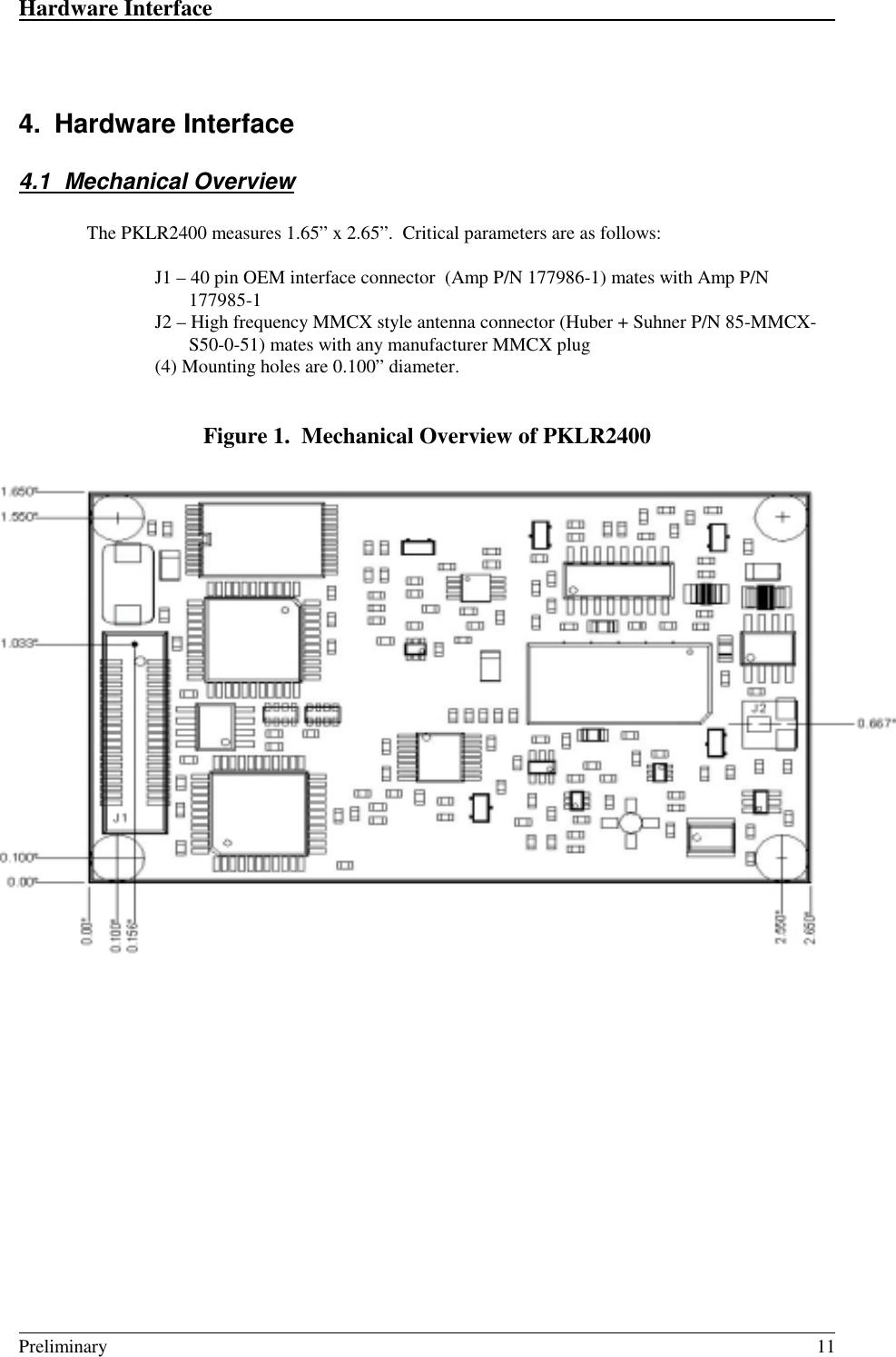
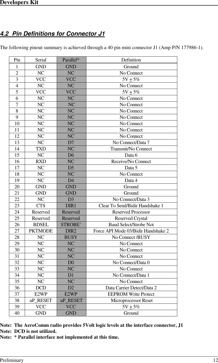
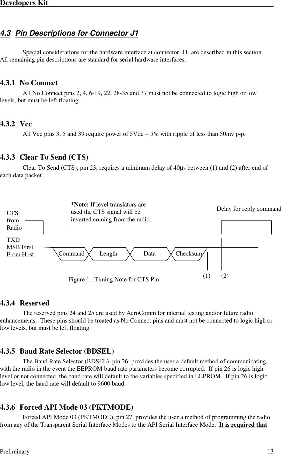
Laird Connectivity PKLR2400 User Manual Aerocomm OEM Radio

AeroComm Corporation Aerocomm OEM Radio

Exhibit 14 AeroComm PKLR2400 Radio Users Manual
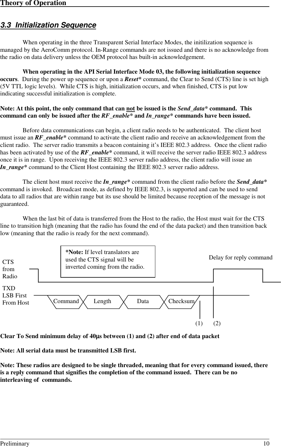
PKLR2400 RadioHardware and SoftwareInterface SpecificationVersion 3.113256 W. 98th StreetLenexa, KS  66215(800) 492-2320www.aerocomm.comwireless@aerocomm.com!!!!!!!!!!!!!!!!!!!!!!!!!!!!!!!!!!!!!!!!!!!!!!!!!!!!!!!!!!!!!!!!!!!!!!
Copyright Information/FCC User’s NoticeCopyright Copyright © 1999 AEROCOMM, Inc. All rights reserved.Information The information contained in this manual and the accompanyingsoftware programs are copyrighted and all rights are reserved byAEROCOMM, Inc. AEROCOMM, Inc. reserves the right to makeperiodic modifications of this product without obligation to notifyany person or entity of such revision.  Copying, duplicating, selling,or otherwise distributing any part of  this product without the priorconsent of an authorized representative of AEROCOMM, Inc. isprohibited.All brands and product names in this publication are registeredtrademarks or trademarks of their respective holders.FCC USER'SNotice WARNING:  This equipment has been tested and found to comply with the limits for aClass B digital device, pursuant to Part 15 of the FCC Rules. These limitsare designed to provide reasonable protection against harmfulinterference when the equipment is operated in a residential environment.This equipment generates, uses, and can radiate radio frequency energyand, if not installed and used in accordance with the instruction manual,may cause harmful interference to radio communications. However, thereis no guarantee that interference will not occur in a particular installation.If this equipment does cause harmful interference to radio or televisionreception, which can be determined by turning the equipment off and on,the user is encouraged to try to correct the interference by one or more ofthe following measures:• Reorient or relocate the receiving antenna• Increase the separation between the equipment and receiver.• Connect the equipment into an outlet on a circuit different from theone the receiver is connected.
Revision s DescriptionVersion 1.0 Initial Release Version  - 2/4/99Version 1.1 page 24 - System ID Address corrected from 30h to 34hVersion 2.0 Add transparent serial modes – 5/25/1999Added EEPROM Write ProtectChanged Pin 27 Definition to Forced API Mode 03Version 3.0 Add broadcast packet attempts – 6/10/1999Broadcast Packet size increased from 256Bytes to 2KBytesVersion 3.1 Correct number of channels from 75 to 77 – 7/22/1999Change nomenclature for Serial Packet Mode 03 to Serial API Mode 03Copyright © 1999AeroComm, Inc.This material is preliminary.Information furnished by AeroComm in this specification is believed to be accurate.  Devices sold byAeroComm are covered by the warranty and patent indemnification provisions appearing in its Terms ofSale only.  AeroComm makes no warranty, express, statutory, implied or by description, regarding theinformation set forth herein.  AeroComm reserves the right to change specifications at any time and withoutnotice.AeroComm’s products are intended for use in normal commercial applications.  Applications requiringextended temperature range or unusual environmental requirements such as military, medical life-support orlife-sustaining equipment, are specifically not recommended without additional testing for such application.
Table of Contents                                                                                                                                                                            Preliminary 41. OVERVIEW.......................................................................................................................................... 62. PKLR2400 SPECIFICATIONS........................................................................................................... 73. THEORY OF OPERATION................................................................................................................ 83.1 DEFINITIONS .................................................................................................................................... 83.2 SERIAL INTERFACE MODES.............................................................................................................. 83.2.1 Serial Interface Mode 01 – Transparent, Fixed Length, with Timeout................................... 83.2.2 Serial Interface Mode 02 – Transparent, End Character....................................................... 83.2.3 Serial Interface Mode 03 – API .............................................................................................. 93.2.4 Serial Interface Mode 04 – Transparent, Fixed Length, No Timeout ..................................... 93.2.5 Serial Interface Buffer............................................................................................................. 93.3 INITIALIZATION SEQUENCE ............................................................................................................ 104. HARDWARE INTERFACE.............................................................................................................. 114.1 MECHANICAL OVERVIEW............................................................................................................... 114.2 PIN DEFINITIONS FOR CONNECTOR J1............................................................................................ 124.3 PIN DESCRIPTIONS FOR CONNECTOR J1 ......................................................................................... 134.3.1 No Connect............................................................................................................................ 134.3.2 Vcc ........................................................................................................................................ 134.3.3 Clear To Send (CTS)............................................................................................................. 134.3.4 Reserved................................................................................................................................ 134.3.5 Baud Rate Selector (BDSEL)................................................................................................ 134.3.6 Forced API Mode 03 (PKTMODE) ...................................................................................... 134.3.7 Microprocessor Reset (uP RESET)....................................................................................... 144.3.8 EEPROM Write Protect (E2WP) .......................................................................................... 145. DEVELOPERS KIT ........................................................................................................................... 155.1 SERIAL ADAPTER BOARD............................................................................................................... 16NOTE: The pins on the 40 pin header strip match up 1 to 1 with the pin-out of the OEM Connector J1.16J3-J9 Level Translator Settings ................................................................................................................ 175.1.1 Serial Adapter Board Pin Definitions................................................................................... 175.2 SOFTWARE UTILITIES ..................................................................................................................... 175.2.1 OEM.EXE.............................................................................................................................. 185.2.2 *.RTC .................................................................................................................................... 195.2.3 PORTS.CFG.......................................................................................................................... 205.2.4 Setup Scripts.......................................................................................................................... 205.3 ANTENNA BOARD .......................................................................................................................... 225.4 POWER SUPPLY SPECIFICATION...................................................................................................... 226. COMMAND SET................................................................................................................................236.1 SYSTEM COMMAND SET SUMMARY............................................................................................... 236.1.1 Reset*.................................................................................................................................... 236.1.2 Control*................................................................................................................................ 246.1.3 Diagnostic result*................................................................................................................. 246.1.4 Standby*  (THIS COMMAND NOT YET SUPPORTED)...................................................... 256.1.5 Reset EEPROM*................................................................................................................... 256.1.6 Status Request*..................................................................................................................... 256.1.7 Status Reply*......................................................................................................................... 266.1.8 Update EEPROM Checksum*............................................................................................... 276.1.9 Check EEPROM Checksum* ................................................................................................ 276.1.10 EEPROM Checksum Status*................................................................................................. 276.1.11 Acknowledge* ....................................................................................................................... 276.2 RADIO COMMAND SET SUMMARY ................................................................................................. 286.2.1 RF enable*............................................................................................................................ 28
PKLR                                                                                                                                                                                                                                                                                                                 Preliminary 56.2.2 Send data*............................................................................................................................. 286.2.3 Send data complete* ............................................................................................................. 296.2.4 Received data*...................................................................................................................... 296.2.5 In range*............................................................................................................................... 296.2.6 Out of range*........................................................................................................................ 307. CONFIGURING THE PKLR2400 RADIO...................................................................................... 317.1 SYSTEM EEPROM PARAMETERS .................................................................................................. 317.1.1 Product Identifier String/Version Information...................................................................... 317.1.2 IEEE assigned MAC Address................................................................................................ 317.1.3 Channel Number................................................................................................................... 327.1.4 Client/Server Mode ............................................................................................................... 327.1.5 System ID .............................................................................................................................. 327.1.6 Baud High (BH) and Baud Low (BL).................................................................................... 337.2 PROTOCOL EEPROM PARAMETERS.............................................................................................. 347.2.1 Transmit Data Link Attempts ................................................................................................357.2.2 Receive mode ........................................................................................................................ 357.2.3 In-Range, Out-of-Range Refresh........................................................................................... 357.2.4 End Character Definition...................................................................................................... 367.2.5 Fixed Packet Length High Byte/Low Byte............................................................................. 367.2.6 Serial Interface Modes.......................................................................................................... 367.2.7 Destination Address Control................................................................................................. 377.2.8 Interface Timeout Control..................................................................................................... 377.2.9 Broadcast Attempts ............................................................................................................... 387.3 EEPROM PARAMETER SUMMARY................................................................................................ 388. INITIALIZING THE PKLR2400 RADIO........................................................................................ 39
Overview                                                                                                                                                                                                                                                                                                            Preliminary 61. OverviewThis document contains information about the hardware and software interface between anAeroComm PKLR2400 Radio and an OEM host.  Information includes the theory of operation, systemissues, and a basic command set for operational control of the system and radio.The Radio is designed to allow flexibility at the hardware interface level with a minimum numberof actual hardware pins connecting the radio and the OEM Product.  The radio is controlled by a Dallas87C520 microcontroller providing program storage.  A separate EEPROM provides user definableparameter storage.The RF system is a Client/Server (Slave/Master) architecture.  Data can be transmitted from clientto server or server to client, but not from client to client, or server to server.  Clients can only hear serversand servers can only hear clients.The Serial Interface Modes provide four main serial user interfaces.  This protocol providessignificant flexibility to the OEM allowing them to provide data in many forms including packet, endcharacter and fixed-length with and without timeouts.
PKLR2400 Specifications                                                                                                                                                                                                                                                                                 Preliminary 72. PKLR2400 SpecificationsGENERALBus Interface Serial (TTL Level Asynchronous) or Parallel through 40pin mini connector. Amp P/N 177986-1 or BergInterface Data Rate     Serial     Parallel Prog to 800 kbps.  Supports PC rates to 57.6 Kbps4 MbpsCompliance Certifiable under:     US - FCC15.247     Canada - DOC     Europe - ETSI     Japan - MKKPower Consumption     TX/RX Active (All Modes)     Interface ON/RF OFF (API Mode Only)     Sleepwalk (All Modes)     Standby (API Mode Only)115mA typical45mA typical35mA typical30mA typicalChannels Supports 77 non-interfering channelsSecurity User assigned System ID.  Unique IEEE address on eachradio.RADIOFrequency Band 2.402 – 2.478 GHzRadio Type Spread Spectrum Frequency HoppingOutput Power 10mWVoltage 5V nominal +5%, + 50mV rippleSensitivity -90dBmData Rate 1MbpsRange Indoors up to 300ft, Outdoors up to 3000ftCan be extended with directional antennaENVIRONMENTALTemperature (Operating) 0 to +60 CTemperature (Storage) -50 to +85 CHumidity (non-condensing) 10% to 90%PHYSICALDimensions 1.65” x 2.65” x 0.20”Antenna Connector Standard MMCX jackWeight Less than 0.5 ounceSOFTWAREUser Configurable Options     Host Interface Data Rate Up to 800Kbps     Variable Packet Length Up to 2Kbyte     Serial Interface Modes (3) Transparent and (1) API     Diagnostic Error Counters     User Programmable Attempts Up to 255
PKLR2400 Specifications                                                                                                                                                                                                                                                                                 Preliminary 83.  Theory of Operation3.1 DefinitionsServer Host: The server host is the OEM device controlling the server radioClient Host: The client host is the OEM device controlling the client radioHost: Host refers to both the server host and the client hostServer Radio: The server radio is the “master” radio.  It is the hub of communicationsClient Radio: The client radio is a “slave” radio.  It is controlled by it’s own Host, but is a slave to theserver radioAuthentication: The acquisition of the IEEE 802.3 address of the Server Radio by the Client Radio and thesubsequent issuance of an In-Range* command by the Client Radio to the Client Host.Unicast Address: A frame that is directed to a single recipient as specified in IEEE 802.3.Broadcast Address: A frame that is directed to multiple recipients as specified in IEEE 802.3.3.2  Serial Interface ModesThe PKLR2400 provides four Serial Interface Modes with programmability within each modeallowing maximum system flexibility.  These four Serial Interface Modes include three transparent modesand one API mode.  The radio-to-radio protocol is identical on all three Transparent Serial Interface Modes.This allows all three Transparent Serial Interface Modes to coexist within the same network.  The APISerial Interface Mode 03 is not interoperable with the Transparent Serial Interface Modes 01, 02 and 04.3.2.1 Serial Interface Mode 01 – Transparent, Fixed Length, with TimeoutMode 01 specifies Transparent mode with fixed length packets and active timeout.  Packets will betransmitted over the RF interface when one of the following conditions occurs:• The number of data bytes received over the interface is equal to the buffer specified bythe user in EEPROM address locations 43H and 44H.• A byte gap larger the timeout specified by the user in EEPROM location 4DH occurs.3.2.2 Serial Interface Mode 02 – Transparent, End CharacterMode 02 specifies Transparent mode with End Character.  Packets will be transmitted over the RFinterface when the user-defined End Character is received by the radio over the interface.  The EndCharacter is defined by the user at EEPROM location 3EH.
Theory of Operation                                                                                                                                                                                                                                                                                         Preliminary 93.2.3 Serial Interface Mode 03 – APIMode 03 specifies API Mode.  In this mode, the OEM has control of the radio command setdetailed in Section 6.2.  Packets are transmitted upon completion of the Send_Data command.In API Serial Interface Mode 03, the OEM host may utilize a set of basic commands to control theradio and system.  These commands allow the customer to establish system parameters through theprogramming of variables in EEPROM as well as monitoring system performance.  These commands canonly be exercised when the radio is in API Serial Interface Mode 03. It is important to understand twoaspects of the software commands.1. There are only three commands that are issued from the client radio to the Client Host. Thesethree commands are Out_of_range*, In_range* and  Receive_data*.  The Receive_data*command is the only command issued from the Server radio to the Server Host.   It isimportant to note that these commands will NOT get an acknowledgement, they are signals tothe Host to alert it to incoming data, or a change of status.2. All remaining commands initiated by the Host MUST receive an acknowledge from the radioto signal completion of the assigned task.  This works as flow control for the informationgoing to the radio.The server radio can receive data from a total of 75 different clients, but from only 8 differentclients in any 30 millisecond interval.  It is possible that there will be multiple Receive_data* commands atthe same time. Since there is no reply command at the completion of Receive_data*, the Host must becapable of handling up to 8 Receive_data* commands at one time.Note: This means that whenever a command is initiated by the radio to the Host, the Host must beready to accept the command and any data following the command.Note:  A full list of commands, definitions, and implementation can be found in Section 6.3.2.4 Serial Interface Mode 04 – Transparent, Fixed Length, No TimeoutMode 04 specifies Transparent mode with fixed length packets and no timeout.  Packets will betransmitted over the RF interface when the number of data bytes received over the interface is equal to thebuffer specified by the user in EEPROM address locations 43H and 44H.3.2.5 Serial Interface BufferThe serial interface buffer provides 8Kbytes of memory broken into four dynamic regions.  In theAPI Serial Interface Mode 03, only one region is utilized.  In the Transparent Serial Interface Modes 01, 02and 04, a buffer region is used each time a packet release condition is met.  As an example, in EndCharacter Mode 02, if 500 bytes are transmitted followed by the specified end character, 500 bytes will bestored in the first region and the remianing 7.5Kbytes will be dynamically allocated for the next threepackets.  It is strongly recommended that CTS or upper layer protocol with acknowledgements be used bythe OEM when operating in Transparent Serial Interface Control Modes to eliminate the following systemissues:Note:  If all four buffers are filled and the OEM host continues to send data over the interface, it willbe discarded by the radio.  This can be eliminated if the OEM utilizes CTS.
Theory of Operation                                                                                                                                                                                                                                                                                         Preliminary 103.3 Initialization SequenceWhen operating in the three Transparent Serial Interface Modes, the initilization sequence ismanaged by the AeroComm protocol. In-Range commands are not issued and there is no acknowledge fromthe radio on data delivery unless the OEM protocol has built-in acknowledgement.When operating in the API Serial Interface Mode 03, the following initialization sequenceoccurs.  During the power up sequence or upon a Reset* command, the Clear to Send (CTS) line is set high(5V TTL logic levels).  While CTS is high, initialization occurs, and when finished, CTS is put lowindicating successful initialization is complete.Note: At this point, the only command that can not be issued is the Send_data* command.  Thiscommand can only be issued after the RF_enable* and In_range* commands have been issued.Before data communications can begin, a client radio needs to be authenticated.  The client hostmust issue an RF_enable* command to activate the client radio and receive an acknowledgement from theclient radio.  The server radio transmits a beacon containing it’s IEEE 802.3 address.  Once the client radiohas been activated by use of the RF_enable* command, it will receive the server radio IEEE 802.3 addressonce it is in range.  Upon receiving the IEEE 802.3 server radio address, the client radio will issue anIn_range* command to the Client Host containing the IEEE 802.3 server radio address.The client host must receive the In_range* command from the client radio before the Send_data*command is invoked.  Broadcast mode, as defined by IEEE 802.3, is supported and can be used to senddata to all radios that are within range but its use should be limited because reception of the message is notguaranteed.When the last bit of data is transferred from the Host to the radio, the Host must wait for the CTSline to transition high (meaning that the radio has found the end of the data packet) and then transition backlow (meaning that the radio is ready for the next command).Clear To Send minimum delay of 40µµµµs between (1) and (2) after end of data packetNote: All serial data must be transmitted LSB first.Note: These radios are designed to be single threaded, meaning that for every command issued, thereis a reply command that signifies the completion of the command issued.  There can be nointerleaving of  commands.CTSfromRadioDelay for reply command*Note: If level translators areused the CTS signal will beinverted coming from the radio.TXDLSB FirstFrom Host  Command  Length ChecksumData(1) (2)
Hardware Interface                                                                                                                                                                                                                                                                                          Preliminary 114. Hardware Interface4.1 Mechanical OverviewThe PKLR2400 measures 1.65” x 2.65”.  Critical parameters are as follows:J1 – 40 pin OEM interface connector  (Amp P/N 177986-1) mates with Amp P/N177985-1J2 – High frequency MMCX style antenna connector (Huber + Suhner P/N 85-MMCX-S50-0-51) mates with any manufacturer MMCX plug(4) Mounting holes are 0.100” diameter.Figure 1.  Mechanical Overview of PKLR2400
Developers Kit                                                                                                                                                                                                                                                                                                   Preliminary 124.2  Pin Definitions for Connector J1The following pinout summary is achieved through a 40 pin mini connector J1 (Amp P/N 177986-1).Pin Serial Parallel* Definition1 GND GND Ground2NC NC No Connect3VCC VCC 5V + 5%4NC NC No Connect5VCC VCC 5V + 5%6NC NC No Connect7NC NC No Connect8NC NC No Connect9NC NC No Connect10 NC NC No Connect11 NC NC No Connect12 NC NC No Connect13 NC D7 No Connect/Data 714 TXD NC Transmit/No Connect15 NC D6 Data 616 RXD NC Receive/No Connect17 NC D5 Data 518 NC NC No Connect19 NC D4 Data 420 GND GND Ground21 GND GND Ground22 NC D3 No Connect/Data 323 CTS DIR1 Clear To Send/Bidir Handshake 124 Reserved Reserved Reserved Processor25 Reserved Reserved Reserved Crystal26 BDSEL STROBE’ Baud Select/Strobe Not27 PKTMODE DIR2 Force API Mode 03/Bidir Handshake 228 NC BUSY No Connect /BUSY29 NC NC No Connect30 NC NC No Connect31 NC NC No Connect32 NC D0 No Connect/Data 033 NC NC No Connect34 NC D1 No Connect/Data 135 NC NC No Connect36 DCD D2 Data Carrier Detect/Data 237 E2WP E2WP EEPROM Write Protect38 uP_RESET uP_RESET Microprocessor Reset39 VCC VCC 5V + 5%40 GND GND GroundNote:  The AeroComm radio provides 5Volt logic levels at the interface connector, J1Note:  DCD is not utilized.Note:  * Parallel interface not implemented at this time.
Developers Kit                                                                                                                                                                                                                                                                                                   Preliminary 134.3  Pin Descriptions for Connector J1Special considerations for the hardware interface at connector, J1, are described in this section.All remaining pin descriptions are standard for serial hardware interfaces.4.3.1 No ConnectAll No Connect pins 2, 4, 6-19, 22, 28-35 and 37 must not be connected to logic high or lowlevels, but must be left floating.4.3.2 VccAll Vcc pins 3, 5 and 39 require power of 5Vdc + 5% with ripple of less than 50mv p-p.4.3.3 Clear To Send (CTS)Clear To Send (CTS), pin 23, requires a minimum delay of 40µs between (1) and (2) after end ofeach data packet.Figure 1.  Timing Note for CTS Pin4.3.4 ReservedThe reserved pins 24 and 25 are used by AeroComm for internal testing and/or future radioenhancements.  These pins should be treated as No Connect pins and must not be connected to logic high orlow levels, but must be left floating.4.3.5 Baud Rate Selector (BDSEL)The Baud Rate Selector (BDSEL), pin 26, provides the user a default method of communicatingwith the radio in the event the EEPROM baud rate parameters become corrupted.  If pin 26 is logic highlevel or not connected, the baud rate will default to the variables specified in EEPROM.  If pin 26 is logiclow level, the baud rate will default to 9600 baud.4.3.6 Forced API Mode 03 (PKTMODE)Forced API Mode 03 (PKTMODE), pin 27, provides the user a method of programming the radiofrom any of the Transparent Serial Interface Modes to the API Serial Interface Mode.  It is required thatCTSfromRadioDelay for reply command*Note: If level translators areused the CTS signal will beinverted coming from the radio.TXDMSB FirstFrom Host  Command  Length ChecksumData(1) (2)
Developers Kit                                                                                                                                                                                                                                                                                                   Preliminary 14the radio be in API Serial Interface Mode to execute the Command Set or to configure any of theEEPROM parameters.  To force the radio into API Serial Interface Mode 03, pin 27 must be held at logiclow level and the radio reset.  The radio can not be placed into any of the Transparent Serial InterfaceModes 01, 02 or 04 until pin 27 is held at logic high level and reset.4.3.7 Microprocessor Reset (uP RESET)Microprocessor Reset (uP RESET) is achieved by holding pin 38 at logic high level for aminimum of 2ms.  If uP RESET is performed after power has been applied to the radio and is stable, thereset time will be significantly less.  At all other times, pin 38 should be logic low level.  If pin 38 is notconnected, the microprocessor will hold pin 38 at logic low level.4.3.8 EEPROM Write Protect (E2WP)EEPROM Write Protect  (EEWP) is enabled when pin 37 is at logic high level or left floating.  Pin37 must be logic low level to Write to the EEPROM.
Developers Kit                                                                                                                                                                                                                                                                                                   Preliminary 155. Developers KitSDK-PKLR2400P (Parallel) and SDK-PKLR2400S (Serial) Developer Kits help system designersimplement radio designs quickly.  The kit offers all the cables, power supplies, circuit schematics, documentationand accessories needed to begin using the PKLR2400 quickly.The kit includes:• (2) PKLR2400 Data Radios either serial or parallel• (2) Serial Adapter Boards with 40 pin interface, 40 pin header, LED indicators, power connector and DB9connector. (SDK-PKLR2400S includes RS232 transceivers)• (2) AC Power Adapters• (2) DB9 to DB9 or (2) DB9 to DB25 for the SDK-PKLR2400S and SDK-PKLR2400P respectively• Hardware and software interface specification• (2) Antenna cables with patch antenna (monopole or dipole antenna optional)• Software utilities• Technical Support
Developers Kit                                                                                                                                                                                                                                                                                                   Preliminary 165.1  Serial Adapter BoardThe Serial Adapter Board allows the use of different forms of communication with the OEMradios.  The user must choose between using RS-232 levels or 5 Volt TTL logic levels for interfacing withthe OEM radio when using the adapter board.Figure 2.  Serial Adapter Board Assembly DrawingItem Qty Reference Description11 J1 Amp 40 Pin Connector (177985-1) mates directly with J1 on Radio2 1 J2 DB9 Male connector mates with provided cable to PC or OEM Host3 1 P1 Power Connector provides power to entire kit with provided 5Vdc PS4 2 J10 Generic 40 Pin Dip Header 0.100 Centers for test points5 7 J3-9 Generic 3 Pin Sip Header 0.100 Centers for level translator selection6 2 U1-2 Max202 Voltage Level Conversion Chips7 1 SW1 SPST Switch for Reset8 1 SW2 EEPROM Write Enable when DepressedNOTE: The pins on the 40 pin header strip match up 1 to 1 with the pin-out of the OEM ConnectorJ1.
Developers Kit                                                                                                                                                                                                                                                                                                   Preliminary 17J3-J9 Level Translator SettingsIf a PC will be used as the OEM server or client host, then level conversion must be enabled toconvert from the RS-232 levels at the PC to the 5 Volt TTL logic levels used on the radio.  To enable levelconversion, place jumpers J3-J9 on pins 2 and 3, see Figure 3.  If another device (0-5 volt TTL logic levels)is to act as the Host for the radio then the user must disable level conversion.  To disable level conversion,place jumpers J3-J9 on pins 1 and 2 see figure 4.  If running under Windows, jumper J6(PKTMODE/RTS) must be removed.Figure 3.  Level Translation Enabled Figure 4.  Level Translation DisabledNote: If level translation is enabled it is important to note that the signal level will be inverted at theinterface connector, J1, between the OEM radio and the Serial Adapter Board.Figure 5.  Jumper Definitions.5.1.1 Serial Adapter Board Pin DefinitionsDB-9 Signal Name Associated 40-pin connector 40-Pin Header Strip(RS-232C) Level Translation to radio Test PointsPin # At DB-9 Connector  Jumper Pin # Pin #1 DCD not used J9 NC 352 RX Data J3 14 143 TX Data J4 16 164NC5 Ground 1,20,21,40 1,20,21,406NC7 PKTMODE/RTS J6 27 278 Clear to Send J5 23 239NC NC NC5.2 Software UtilitiesJumper Associated Serial SignalFrom DB-9J3 RX DataJ4 TX DataJ5 Clear to SendJ6 PKTMODE/RTSJ7 NAJ8 NAJ9 DCD not used
Developers Kit                                                                                                                                                                                                                                                                                                   Preliminary 18The developer kit includes a 3.5” diskette of software utilities allowing the customer to exercisethe radios upon receipt.  The software utilities are written for a DOS environment.  The softwareutilities will not operate properly under a DOS shell in Windows or Windows.  The software includesseveral files as follows:• OEM.EXE – Interactive Command/EE Edit Software/Transmit Receive Emulator.• *.RTC – Script files that automate radio mode setup and demonstrates operation.• PORTS.CFG – Com port address and baud rate information• README.TXT – Further utility software documentation and latest release notes• OEM.CFG – Configuration file for OEM.EXE• OEMRWSP.INI – AeroComm Use OnlyThese files are located in each of three directories as follows:1. OnePC – This directory contains all the files required to run the Client and Server radios on a singlePC.  The Client Radio must be connected to Com1 (3F8) and the Server Radio must be connected toCom 2 (2F8)2. ClientPC- This directory contains the Client Radio files that are required to run the Client Radio onone PC and the Server Radio on a separate PC.  The Client Radio should be connected to Com 1 (3F8)3. ServerPC- This directory contains Server Radio files that are required to run the Client Radio on onePC and the Server Radio on a separate PC.  The Server Radio should be connected to Com 1 (3F8)5.2.1 OEM.EXEThis software contains three unique utilities to exercise, monitor and setup modes in the radios.These utilities are: Transmit/Receive Emulator, Single Line Command Interface, and EEPROMViewer/Editor.5.2.1.1 Transmit/Receive EmulatorThis software allows (1) Server and (1) Client radio to communicate with each other.  Thesoftware comes pre-configured for the two radios in the development kit.When connecting the Client and Server Radios to the same PC, connect the Server Radio toCom 2 (2F8), then connect the Client Radio to Com 1 (3F8).  Copy the OnePC directory and contents to thePC.When connecting the Client and Server Radios to separate PCs, connect the Server Radio toCom 1 (3F8) on one PC, then connect the Client Radio to Com 1 (3F8) on a separate PC.  Copy theClientPC directory and contents to the PC with the Client Radio attached.  Copy the ServerPC directory andcontents to the PC with the Server Radio attached.Note:  The factory default for the Client Radio and Server Radio is API Serial Interface Mode 03.Run OEM.EXE on one or both PCs as dictated by your setup.  Press the 'F3' key to perform aRESET and RF_Enable on all PCs.  Press the 'F9' key to run the script files and demonstrate continuousdata transfers between radios.  Press the 'Esc' key to stop.  Pressing the 'Esc' key again will exit from theprogram.Note:  The “F3” key should be used only when the radios are in API Serial Mode 03.  Use “Alt R” toperform a RESET of the radios in Transparent Serial Modes 01, 02 and 04.While running, the screen will display transmit timeouts, receive timeouts, and run number.  TheEmulator program is controlled by script files.  The script files can be edited by the user and detailed
Developers Kit                                                                                                                                                                                                                                                                                                   Preliminary 19instructions on how to write a script file can be found in the section below describing *.RTC.  While in theEmulator, pressing the ‘Alt’ key will bring up a window with 7 choices: File, Settings, Window, Reset,Enable, Help and About.  The File option allows the user to load a script file or execute a mode setup scriptto ports 1 or 2.  The Settings option allows the user to change baud rate and other settings.  The Windowoption allows the user to view the trace buffer or a list of the script commands. The Reset command issues aReset command to all ports configured in PORTS.CFG.  The Enable command sends a RF_Enable to allports configured in PORTS.CFG.Note:  The factory default for the Client Radio and Server Radio is API Serial Interface Mode 03.Therefore, both radios must receive an RF_enable before scripts can be run.Note:  Receive commands expecting more than 16 bytes will fail in 'F10' single-step mode.The Transmit/Receive Emulator can also be used to execute the setup scripts provided with theprogram.  For a full list of the scripts, see the readme.txt file in the directory labeled ‘Scripts’ on the disk.To execute a script, press ‘alt-F’ and then ‘Enter’ to bring up a selection window.  You can enter the nameof the setup script to be run, or hit ‘Enter’ to see a list of all the available script files.  It is important to notethat when you hit ‘Enter’ it will show all the script files that are in the same directory as the executableoem.exe.  Once you have a script file loaded, then you will need to depress the write protect tab on theserial adapter board while you single step (‘F10’) through the commands in the script.  Once you haveexecuted all the commands in the set-up script you must press the reset button on the serial adapter boardbefore any of the changes will be implemented.5.2.1.2 Single Line Command InterfaceWhile in the Transmit/Receive Emulator press the ‘F5’ key to enter into the One Line CommandInterface.  The one line Command Interface allows the user to command the radios into various operationmodes.  The command set has already been entered.  To invoke a command, scroll to the appropriatecommand, using the up/down arrows on the keyboard, until the appropriate command is highlighted.  Pressthe 'F10' key to send the command to the radio.  Press the 'F9' key to continuously retransmit the samecommand until the 'Esc' key is pressed.  Press the 'F8' key to toggle between ports 1 and 2 (com1 andcom2).  You will see the active port and address displayed at the top of the screenUpon successfully receiving and executing the command, the radio will send back a acknowledgedisplayed in the "Receive Data" window.  At the end of each command sequence line, a highlightedchecksum is displayed.  When entering a new command, it is not necessary to enter a checksum.  Theprogram automatically calculates and enters the checksum.  On exit, changes to the command interface caneither be saved or ignored.  Press the 'Esc' key to exit.5.2.1.3 EEPROM Viewer/EditorPress the 'F2' key to enter the EEPROM viewer/editor screen.  To edit a value on this screen,simply move the cursor to highlight the appropriate value, type in the new value and press the 'Enter' key.To undo an edit, either press the 'Esc' key to return to the Command Interface, or press any arrow key.  Toupdate the radio with the new EEPROM values, press the 'F10' key.  An EEPROM read can be performedon this page by pressing the 'F9' key.5.2.2 *.RTC
Developers Kit                                                                                                                                                                                                                                                                                                   Preliminary 20*.RTC files contain all of the configuration information for OEM.EXE.  *.RTC files can bemodified to change timeouts, ports, and commands.  *.RTC files require very specific format as detailedbelow:*  -- begins and ends each command sequenceT  -- invoke transmit sequence over serial host/radio interface (API Mode 3)R  -- invoke receive sequence over serial host/radio interface (API Mode 3)C  -- invoke transmit sequence over serial host/radio interface (Transparent Modes 1,2,4)S  -- invoke receive sequence over serial host/radio interface (Transparent Modes 1,2,4)D  -- invoke delay   Note:  Any line beginning with a "space" character is interpreted as a comment   Note:  The first line in PING.RTC is always interpreted as a commentExample Command Format*T[transmit port number] [timeout][transmit port number] is either "1" or "2" as designated in PORTS.CFG[timeout] is between "0000" and "9999" and is measured in milliseconds[Command] [Length Low] [Length High] [Data] [Checksum automatically provided]*5.2.3 PORTS.CFGBefore attempting to run the executables, the user must ensure the development kit radios areattached to the two ports specified in PORTS.CFG.  The default configuration for PORTS.CFG assumesthat both developer kit radios are connected to the same computer.The default baud rate in PORTS.CFG is 57600.  This should not be changed unless theEEPROM has been corrupted.  In the event of corrupted EEPROM, hit “AltS” in the OEM.EXE programto change the baud rate to 9600 and pin 26 on the interface connector, J1, of the radio must be logic lowlevel to communicate.Note:  If the EEPROM parameters for baud rate are changed, and the radio is reset, these utilitieswill not communicate with the radio until pin 26 is held at logic low level and the third line ofPORTS.CFG is changed to 9600.5.2.4 Setup ScriptsAeroComm provides several scripts to allow easy setup and configuration for different modes.  These setupscripts are as follows:S1AC.RTC – Setup client radio to Mode 1 AddressedS1AS.RTC – Setup server radio to Mode 1 AddressedS1NC.RTC– Setup client radio to Mode 1 Non-AddressedS1NS.RTC– Setup server radio to Mode 1 Non-AddressedS2AC.RTC– Setup client radio to Mode 2 AddressedS2AS.RTC– Setup server radio to Mode 2 AddressedS2NC.RTC– Setup client radio to Mode 2 Non-AddressedS2NS.RTC– Setup server radio to Mode 2 Non-AddressedS4AC.RTC– Setup client radio to Mode 4 AddressedS4AS.RTC– Setup server radio to Mode 4 AddressedS4NC.RTC– Setup client radio to Mode 4 Non-Addressed
Developers Kit                                                                                                                                                                                                                                                                                                   Preliminary 21S4NS.RTC– Setup server radio to Mode 4 Non-AddressedSP3CS.RTC –This file is used to configure both the client and server radio into Mode 3 Receive mode 1(Unicast/Broadcast).SP3CS02.RTC – This file is used to configure both the client and server radio into Mode 3, receive mode 2(unicast only)SP3CS03.RTC – This file is used to configure both the client and server radio into Mode 3, receive mode 3(Promiscuous)In general, the filenames are defined as follows:  S – Setup; X – Mode (X= mode1-4); A or N –Addressed or Non-addressed;  C or S – Client or Host.  Example script name: S2NC.RTC, this would be thesetup script to set up the client radio in Mode 2, with Non-addressed broadcast mode enabled.Also included are ping files which provide data to the radios so that out of the box, the radio’s canbe demonstrated.  The included ping files are:PINGT1B.RTC – This file is used when the radios are in Mode 1.  This has big packet size just about 1KPINGT1S.RTC – This file is used when the radios are in Mode 1.  This has small packet size, < 256 BytesPINGT2.RTC – This file is used when the radios are in Mode 2.  Has 0D as the end characterPINGT22.RTC – This file is used when the radios are in Mode 2.  Has 27 as the end character.UNICAST.RTC – This file is used when the radios are in Mode 3.  As the name implies this utilizes unicastpacket structure.BCAST.RTC – This file is used when the radios are in Mode 3.  As the name implies this utilizes broadcastpacket structure.JUNK.RTC – This is a junk packet with no accurate destination or source address, this is used to testpromiscuous mode as well as can be used to prove that such a packet is disregarded in receivemode 1 & 2.PINGP3B.RTC – This file is a joint packet structure to be used in Mode 1 or Mode 3.  It has a broadcastpacket followed by a unicast packet.PINGT4B.RTC – This file is used when the radios are in Mode 4.  This has a big packet size..just about 1KPINGT4S.RTC – This file is used when the radios are in Mode 4.  This has a small packet size, < 256 Bytes
Developers Kit                                                                                                                                                                                                                                                                                                   Preliminary 225.3 Antenna BoardThe developer kits are provided with (2) patch antennae mounted on a ground plane.   In addition,(2) SMA male to MMCX plug, cables are provided to interface the antenna boards to the radio.  Optionalantennae are available for testing.  Antenna selection is instrumental to and will impact overall systemperformance.5.4  Power Supply Specification(2) power supplies are also provided to power both units in the developer kit.  These supplies arerated at regulated 5Vdc and 300ma.
Command Set                                                                                                                                                                                                                                                                                                    Preliminary 236. Command SetThe basic command set consists of several commands from the Host and Radio.  The commandset can be used ONLY when the radio is in Serial Interface API Mode 03 determined by theEEPROM address at 4AH (See Chapter 7, Configuring the PKLR2400).  The command set is designedas follows:Command Length Data ChecksumCommand -- 1 Byte.  This is the actual command from the appropriate processor.Length -- 2 Bytes.  This is the total size of the remaining data for this command.  The length fieldis in little endian format.(i.e. low byte/hi byte). This length does not include the checksum.Data -- N Bytes.  The actual data associated with the command.Checksum -- 1 Byte.  The checksum is a byte-by-byte, bitwise “EXCLUSIVE OR” of the Datablock beginning after the Length.6.1  System Command Set SummaryThe System Commands allow the user to initialize the system and perform general system analysiswhen operating in API Serial Interface Mode 03.Name Command Length Data ChecksumReset* AAH 0H 0H AAHControl* 86H 1 to 5 (depends of sub command) As Required As RequiredDiagnostic Result* 87H As Required As Required As RequiredStandby* 88H No yet supportedReset EEPROM* 89H 0H 0H 89HStatus Request* 8AH 1H 0-reset error counter1-don’t do anything 8AHStatus Reply* 8BH 14H-611H See 5.1.16Update EEPROMChecksum* 8CH 0H 0H 8CHCheck EEPROMChecksum* 8DH 0H 0H 8DHEEPROM ChecksumStatus* 8EH 1H 0-Checksum invalid1-Checksum valid 8EHAcknowledge* As Required 0H As Required6.1.1 Reset*This command is issued from the Host processor to the Radio. This command provides a softwarereset to the PKLR2400 Radio initializing the code at the same location as a hardware reset.  This must befollowed by an RF Enable.
Command Set                                                                                                                                                                                                                                                                                                    Preliminary 246.1.2 Control*The Host processor will issue this command to Write and Read EEPROM as well as for NOP.Sub Command one byte Description2H* Read EEPROM.  Additional data: first two bytesspecify starting address.  Second two bytes specifyending address.8H* NOP.9H* Write EEPROM.  Additional data first two bytesspecify starting address.  Second two bytes specifyending address.  Remaining bytes specify data to bewritten. (Range 00 to 7F)Data Frame:86H Length Low 0H Data ChecksumNote:  Any additional subcommands are reserved by the system and if used may cause systemoperation problems.Note:  Following and EEPROM Write* Command, the user should invoke the Update EEPROMChecksum* command.Note:  Following the EEPROM Write* Command, the user MUST invoke the Reset* command beforeany EEPROM changes will become active.6.1.3 Diagnostic result*The Radio will issue this command upon completion of the diagnostic process.Sub result one byte Description2H* Read EEPROM.  Additional data: first two bytesspecify starting address.  Second two bytes specifyending address.8H* NOP.  Returns 6 bytes (87 02 00 08 00 8D)9H* Write EEPROM status. 0 - Write was successful. 1-Write failed.Data Frame:87H Length Low Length High Data Checksum
Command Set                                                                                                                                                                                                                                                                                                    Preliminary 256.1.4 Standby*  (THIS COMMAND NOT YET SUPPORTED)This command is issued by the Host processor to put the Radio in one of two low power modes.For mode 0, the Radio should disable the radio and enter a low power state.  The hop synching is the onlyallowed operation in this mode.  For mode 1, the Radio should go into deep sleep mode.  The Radio shouldcome out of low power modes when a command is issued from the Host processor. This command requiresan acknowledge.Command: 88HLength: 01HData: 0 - indicates low power mode, 1 - indicates sleep mode.Data Frame:88H 01H 00H Data Checksum6.1.5 Reset EEPROM*This command is sent by the OEM Host to the Radio, the result of which sets the variouslocations/parameters in the EEPROM to their default values. The execution of this command does NOTaffect the IEEE Address and Operation Mode parameters in the EEPROM. This command returns a genericpositive acknowledgment.6.1.6 Status Request*This command is sent by the OEM Host to the Radio to find out the various statistics associatedwith the RF Data Link Layer. The Radio sends back the values of the various parameters/statistics as part ofthe Status Reply command.  1 byte of data is supplied along with the command that determines whether theRadio resets the various Error Counters or not.
Command Set                                                                                                                                                                                                                                                                                                    Preliminary 266.1.7 Status Reply*This command will be sent by the Radio to the OEM Host in response to a Status Requestcommand. All the different parameters pertain to the data link layer and are cumulative totals. Once thiscommand has been sent back to the OEM Product, depending on whether the OEM Product desired an errorcounter variable reset, the reset operation is carried out. The different statistics and their sizes are shownbelow:Name Type Description SizeRadio Time TimeCounter Incremented by 1 every 250ms.  Initialized to0 at power on or reset. Unsigned Byte – 3bytes, Low BytefirstTx Failures ErrorCounter Number of times the Radio was not able todeliver a data frame to the destination Unsigned Long -4 bytesTx Retries ErrorCounter Number of times the Radio had to retry beforedelivering a data frame to the destination Unsigned Long -4 bytesRx Failures ErrorCounter Number of times the Radio had to throw awaya received data frame because of badCRC/checksumUnsigned Long -4 bytesRx Retries ErrorCounter Number of times data frames had to beretransmitted before a valid data frame wasreceivedUnsigned Long -4 bytesNum ActiveRadios Data Counter Number of clients registered to aServer Radio. If the Radio underconsideration is a Client radio, just return 0Unsigned Byte - 1ByteList ofRegisteredRadiosIdentity A list of 6 byte IEEE Addresses of all theradio devices + 3 byte time stamp + 3 bytepacket count. Time stamp and packet counterare reset at power on or RESET.12 bytes * NumReg Client RadiosStatus Reply ExampleName Type 0 Active Radios 2 Active RadiosRadio Time Time Counter 1 Byte – TL1 Byte – TM1 Byte – TH1 Byte – TL1 Byte – TM1 Byte – THTx Failures Error Counter 4 Bytes 4 BytesTx Retries Error Counter 4 Bytes 4 BytesRx Failures Error Counter 4 Bytes 4 BytesRx Retries Error Counter 4 Bytes 4 BytesNum Active Radios Data Counter 0 2List of Registered Radios Identity 6 bytes IEEE Address3 bytes time stamp3 bytes packet count6 bytes IEEE Address3 bytes time stamp3 bytes packet countChecksum Actual ActualData Frame:8BH 17H 00H Data Checksum
Command Set                                                                                                                                                                                                                                                                                                    Preliminary 276.1.8 Update EEPROM Checksum*This command is sent by the Host to the AeroComm module to tell it to recalculate the checksum.This is typically done by the Host CPU after it has completed writing data to the EEPROM on theAeroComm module. The response to this command is an acknowledge.6.1.9 Check EEPROM Checksum*This command is sent by the Host CPU to the AeroComm module to validate the EEPROMchecksum. This is typically done after bringing up the AeroComm module out of reset. The AeroCommmodule reports either a good or a bad checksum, by sending back a response called EEPROM ChecksumStatus6.1.10 EEPROM Checksum Status*This command is sent by the AeroComm module in response to a Check EEPROM Checksumcommand from the Host CPU. The data portion of the command indicates whether the checksum is good orbad, based on which the Host CPU takes the appropriate action.6.1.11 Acknowledge*Some commands in the above set have an implied positive response.  The generic positiveresponse is defined as the command sequence just received retransmitted back with a zero length.
Command Set                                                                                                                                                                                                                                                                                                    Preliminary 286.2  Radio Command Set SummaryThe Radio Commands allow the user to control the flow of data into and out of the radio as well asinitialization of the radio in API Serial Interface Mode 03.Name Command Length Data ChecksumRF enable* 80H 0H 0H 80HSend Data* 81H 1 to 7f0h (includes 802.3 Header) As required As RequiredSend Data Complete* 82H 1H 0 or 1 (see 5.1.4) As RequiredReceived Data* 83H 1 to 7f0h (includes 802.3 Header) As Required As RequiredIn range* 84H 06H IEEE address ofServer Radio As RequiredOut of Range* 85H 0H 0H 85H6.2.1 RF enable*This command is issued from the Host processor to the Radio. The Radio must have this commandissued to it prior to any RF data transfers.  This is a command with no data. Typically, this command isissued to the Radio just after it has been brought out of reset. This enables the RF portion of the Radio andturns the transmitter/receiver ON. This command requires an acknowledge.6.2.2 Send data*This command is issued by the Host to the Radio to send a data frame.  The data frame here is theactual frame that the transport/network protocol wants to send out. The data portion will be delivered to theappropriate RF device. Broadcast frames will be delivered to all registered Client Radios without a RF datalink ACK.  Broadcast frames are not required to reach all destinations.  They are typically sent to everyoneat once.Data Frame:81H Length Low Length High Data ChecksumDestination Address Source Address DataMS Byte…LS Byte MS Byte…LS ByteNote: The Data must include header information as follows:(6)Bytes for the IEEE 802.3 standard destination address and(6)Bytes for the IEEE 802.3 standard source address.These unique IEEE addresses are provided by AeroComm.  See Section 4 forEEPROM locationNote: The Length must include the IEEE 802.3 Header
Command Set                                                                                                                                                                                                                                                                                                    Preliminary 296.2.3 Send data complete*The Radio will issue this command upon completion of the data transmission process, as indicatedby a RF-layer Acknowledgment from the destination RF-device.  An additional byte of data indicates asuccess or a failure code.  This command must be returned for every send data command unless the devicepower fails.Command: 82HLength: 01Data: 0 - indicates success. 1 - Can’t send packet.Checksum: As requiredData Frame:82H 01H 00H Data Checksum6.2.4 Received data*The Radio will issue this command upon reception of data from the RF link.  The information inthe data frame is the received data.Data Frame:83h Length Low Length High Data ChecksumDestination Address Source Address DataMS Byte…LS Byte MS Byte…LS Byte6.2.5 In range*The Client Radio will issue this command upon detecting that it is in range of a Server Radio.  Thiscommand is only valid after reset or after an out of range command has been issued.  This command shouldhave some hysterisis so that the Host processor isn’t flooded with these commands in a fringe coveragearea.  The state of the RF link should be updated with the frequency specified in the Protocol EEPROMParameters, Chapter 7.2, to provide the needed hysterisis.  This command includes the Server RadioIEEE802 Address.Data Frame:84H 06H 00H Data ChecksumServer IEEE  AddressMS Byte…LS ByteNote: This is only valid from the viewpoint of Client Radio.
Command Set                                                                                                                                                                                                                                                                                                    Preliminary 306.2.6 Out of range*The Radio will issue this command upon detecting that it is out of range of a Server Radio.  Thiscommand is only valid after reset or after an in range command has been issued to the Host processor. Thiscommand should have some hysterisis so that the Host processor isn’t flooded with these commands in afringe coverage area.  The state of the RF link should be updated with the frequency specified in theconfiguration command to provide the needed hysterisis.Note:  This is only valid from the viewpoint of a Client Radio.
Configuring the PKLR2400                                                                                                                                                                                                                                                                             Preliminary 317.  Configuring the PKLR2400 RadioThe various configurable parameters are stored in the EEPROM in the Radio. These parametersare read by the AeroComm firmware on power-up reset. These parameters can be configured byAeroComm as AeroComm defaults or customer defaults.  These parameters can also be configured by thecustomer using a PC and an AeroComm provided adapter.  If the customer is writing to the EEPROM, theymust use the Write EEPROM Command and enable E2WP, pin 37, or switch 2 on the serial adapter boardincluded with the developer kit.  The different configurable parameters and their respective EEPROMlocations are highlighted in this chapter.7.1  System EEPROM ParametersThe system EEPROM parameters provide general system configuration information for the radio.These parameters can be monitored and changed independent of the serial interface protocol.  Theseparameters can only be changed when the API Serial Interface Mode 03, described in Section 7.1, isactive.EEPROMAddress Size Description0H 40 bytes Product identifier string/Version Info28H 6 bytes IEEE assigned MAC Address2EH 1 byte Channel number;  Range = 01- 75; Default = 00;33H 1 byte Client/Server mode01 – Server Radio mode02 – Client Radio mode (default)34H 8 bytes System ID - used to demarcate RF networks (default=00 00 00 00 0000 00 01)40H 1 byte Baud High (BH) – Default is FF41H 1 byte Baud Low (BL) – Default is F77.1.1 Product Identifier String/Version InformationEEPROM Address:  0HSize:  40 bytesUseful for OEM to read AeroComm version information.  This information should not beoverwritten by the OEM.  Original information is restored when a RESET EEPROM command is issued.7.1.2 IEEE assigned MAC AddressEEPROM Address:  28HSize:  6 bytesThis is the unique, 6-byte, IEEE 802.3 ethernet address assigned by AeroComm to each radio.This unique address should not be changed.
Configuring the PKLR2400                                                                                                                                                                                                                                                                             Preliminary 327.1.3 Channel NumberEEPROM Address:  2EHSize:  1 byteDefault:  00Range:  01-75This provides 75 unique and non-interfering pseudorandom hopping sequences or channels.  Thisallows for up-to 75 independent, co-located data networks.  Default shipped at 00.  It is highlyrecommended that this be changed to a channel number other than 00.Note:  Channel Number AND System ID between clients and server must be identical for radios tocommunicate.7.1.4 Client/Server ModeEEPROM Address:  33HSize:  1 byteDefault:  02Range:  01-02Specifies whether the radio is operating in the Client Mode (02) or Server Mode (01)7.1.5 System IDEEPROM Address:  31HSize:  8 bytesDefault:  00 00 00 00 00 00 00 01Range: 00 00 00 00 00 00 00 00 to FF FF FF FF FF FF FF FFNote:  Channel Number AND System ID between clients and server must be identical for radios tocommunicate.
Configuring the PKLR2400                                                                                                                                                                                                                                                                             Preliminary 337.1.6 Baud High (BH) and Baud Low (BL)EEPROM Address:  40H and 41H respectivelySize:  1 bytesDefault:  FF for BH and F1 for BLRange: 00-FF for BH and BLBaud High (BH) along with Baud Low (BL) is used to establish the data rate over the interfacebetween the OEM radio and host as follows:Sample BHBL selections for common Baud Rates(Using a 28.224 MHz Crystal)Baud Rate BH BL300 F4 842,400 FE 914,800 FF 489,600 FF A419,200 FF D228,800 FF E157,600 (default) FF F1115,200 Not Supported Not SupportedCustom baud rates can be obtained through the use of the following formula:28.224 * 106BAUD RATE = 32.0 * (65,536 – BH,BL)Note:  The calculated value must be within 3% of the actual value.
Configuring the PKLR2400                                                                                                                                                                                                                                                                             Preliminary 347.2  Protocol EEPROM ParametersThe protocol EEPROM parameters are related to the Serial Mode interface selection.  A summaryof the required EEPROM settings is illustrated in Section 7.3.Note:  These parameters can only be changed when the API Serial Interface Mode 03 is active.When in Transparent Serial Interface Modes, this can be accomplished by holding pin 27,PKTMODE, low and resetting.Note:  When writing to EEPROM using the developer kit, remember to hold the EEPROM writeprotect switch during the write command.EEPROMAddress Size Description2FH 1 byte Transmit data link attempts; Range = 01 - FF;Default = 10H;31H 1 byte Receive mode - determines what type of data frames are received by theOEM Product, based on MAC address of received frame01 - unicast/broadcast data (default)02 - unicast only03 - all (promiscuous mode)32H 1 byte In-Range, Out-of-Range Refresh.  This byte specifies the number of250 ms ticks between range indications.  This gives a range of .05seconds to 12.5 seconds.3EH 1 byte End Character Definition.  This byte specifies the character that will beused to signify the end of a packet.43H 1 byte Fixed Packet Length HIGH BYTE44H 1 byte Fixed Packet Length LOW BYTE4AH 1 byte Serial Interface Modes01 – Transparent, Fixed Length, with Timeout02 – Transparent, End Character03 – API04 – Transparent, Fixed Length, No Timeout4BH 1 byte Destination Address Control00 – Addressed Mode: Destination address is the IEEE 6 bytes at 50H.This mode utilized RF-Layer acknowledges to guarantee delivery of thepacket.01 – Broadcast Mode: No RF-Layer acknowledge, must set Attempts(2FH) to 01.4DH 1 byte Interface Timeout Control00 – 4 mS40 – 40 mS80 – 300 mSC0 – 2.6 S4EH 1 byte Broadcast Attempts; Range 01-FF; Default 04
Configuring the PKLR2400                                                                                                                                                                                                                                                                             Preliminary 357.2.1 Transmit Data Link AttemptsEEPROM Address:  2FHSize:  1 byteDefault: 10HRange:  01-FFThis parameter specifies the maximum number of attempts over the RF interface. Serial Interfacemode 03 will respond with a Send Data Failure when maximum Data Link attempts is achieved.  All othermodes will not receive an acknowledge.Note:  Transmit Data Link Attempts must be set to 01 when operating in the Broadcast Mode of theAddress Transparent Control.7.2.2 Receive modeEEPROM Address:  31HSize:  1 byteDefault:  01Range:  01-03This parameter applies only to API Serial Interface Mode 03.  The default, 01, specifiesUnicast/Broadcast.  Unicast will receive all packets that match the receiving unit IEEE assigned address.Broadcast is achieved by placing  FF in all six bytes of the IEEE assigned destination address sent fromsender.  In Broadcast mode, the receiver will accept all data with a destination address that has FF in all sixbytes.  It is important to note that there is no RF acknowledge on Broadcast packets.  Mode 01 willaccept Unicast and Broadcast data packets and discard all others.  In Unicast only mode, 02, The receivingradio will receive only Unicast packets and discard all others.  In Promiscuous mode, 03, the receiving radiowill accept all packets with the same System ID.Note:  The Receive Mode must be set to 03 in all Transparent Serial Interface Modes including 01, 02and 04 at EEPROM location 4AH.7.2.3 In-Range, Out-of-Range RefreshEEPROM Address:  32HSize:  1 byteDefault:  14HRange:  01-FFThis parameter is used only when the radio is operating in API Serial Interface Mode 03.  The In-Range, Out-of-Range Refresh parameter allows the user to select the interval between which the client radiosearches for Server beacon that includes the Server IEEE source address.  This parameter is very usefulwhen operating in a fringe condition to minimize the In-Range and Out-of-Range commands that may floodthe host. AeroComm has established a default value of 5 seconds through extensive testing.
Configuring the PKLR2400                                                                                                                                                                                                                                                                             Preliminary 367.2.4 End Character DefinitionEEPROM Address:  3EHSize:  1 bytesDefault:  0DRange: 00-FFThis parameter is used only when the radio is operated in Serial Interface Mode 02 specified byEEPROM address 4AH.  Otherwise, this parameter is ignored by the system.  The parameter specified bythe user will indicate the last character in a data packet.  When this end character is seen by the radio, thepacket will be transmitted.  The packet length including the end character can not exceed 2Kbytes.7.2.5 Fixed Packet Length High Byte/Low ByteEEPROM Address:  43H/44HSize:  1 byte eachDefault:  01/00Range: 00/01 to 07/FFHThis parameter is active only when the radio is in Serial Interface Modes 01 or 04 specified byEEPROM address 4AH.  This parameter is ignored in all other modes.  The fixed packet length can notexceed 2Kbytes or it will not be received.7.2.6 Serial Interface ModesEEPROM Address:  4AHSize:  1 bytesDefault:  03Range: 01-04There are four Serial Interface Modes for the OEM radio including one packet mode and threetransparent modes.  All modes are differentiated by the definition of when data will be transmitted by theradio.Mode 01 specifies Transparent mode with fixed length packets and active timeout.  Packets will betransmitted over the RF interface when one of the following conditions occurs:• The number of data bytes received over the interface is equal to the buffer specified bythe user in EEPROM address locations 43H and 44H.• A byte gap larger the timeout specified by the user in EEPROM location 4DH occurs.Mode 02 specifies Transparent mode with End Character.  Packets will be transmitted over the RFinterface when the user-defined End Character is received by the radio over the interface.  The EndCharacter is defined by the user at EEPROM location 3EH.Mode 03 specifies API Mode.  In this mode, the OEM has control of the radio command setdetailed in Section 6.2.  Packets are buffered and transmitted at the direction of the OEM.
Configuring the PKLR2400                                                                                                                                                                                                                                                                             Preliminary 37Mode 04 specifies Transparent mode with fixed length packets and no timeout.  Packets will betransmitted over the RF interface when the number of data bytes received over the interface is equal to thebuffer specified by the user in EEPROM address locations 43H and 44H.Note:  EEPROM parameters can not be programmed once the radios are programmed and reset inany of the Transparent modes 01, 02 or 04.  The radio must be programmed to API mode 03 to accessEEPROM parameters.  This can only be accomplished by holding pin 27 low during and after reset.7.2.7 Destination Address ControlEEPROM Address:  4BHSize:  1 bytesDefault:  00Range: 00-01This parameter sets the destination address for Transparent Serial Interface modes only.  TheAPI Serial Interface Mode 03 utilizes the Receive Mode at EEPROM address 31H to specify addressmodes.  With Destination Address Control set at the default, 00, the radio will determine if the six byteIEEE address at 50H matches.  If the destination address matches, the data packet is forwarded to the OEMhost.  Otherwise the data is discarded.  This addressed mode guarantees delivery of the data packet over theradio link by using aknowledgements.With Destination Address Control set to Broadcast Mode, 01, clients will receive all data packets.There are no acknowledgements and no data packet retries in this mode.Client radios can operate in Destination Address Control Mode 00, providing more reliabledelivery of data to the Server radio.  At the same time, the Server radio can operate in DestinationControl Mode 01, acting as a broadcasting server without guaranteed delivery.  This provides aunique method of implementing a data network of many-to-one or one-to-many.7.2.8 Interface Timeout ControlEEPROM Address:  4DHSize:  1 bytesDefault:  00HRange: 00, 40, 80 or C0The Timeout parameter applies only to the Transparent Serial Interface Mode 01 with fixed lengthpackets and timeout.  This parameter specifies the amount of time between bytes that the radio will waitbefore transmitting the data packet.
Configuring the PKLR2400                                                                                                                                                                                                                                                                             Preliminary 387.2.9 Broadcast AttemptsEEPROM Address:  4EHSize:  1 bytesDefault:  04HRange: 01-FFThe Broadcast Attempt parameter applies only to the Broadcast modes for all four serial packetmodes and specifies the number of times that the RF will broadcast every packet.  The receiving radio willdiscard duplicate packets.7.3  EEPROM Parameter SummaryEEPROM PARAMETERSBYSERIAL INTERFACE MODESAddress Description A B C D E F G H I4AH Serial Interface Mode 01 01 02 02 03 03 03 04 042FH Transmit Attempts 01-FF 01 01-FF 01 01-FF 01-FF 01-FF 01-FF 0131H Receive Mode 03 03 03 03 01 02 03 03 0332H Range Refresh NA NA NA NA 01-FF 01-FF NA NA NA3EH End Char Definition NA NA 00-FF 00-FF NA NA NA NA NA43H Fixed Pkt Length-HB 01-07 01-07 NA NA NA NA NA 01-07 01-0744H Fixed Pkt Length-LB 00-FF 00-FF NA NA NA NA NA 00-FF 00-FF4BHDest Address Control00010001NANANA00014DH Interface Timeout Table Table NA NA NA NA NA NA NAMode DefinitionsA. Mode 01 – Transparent, Fixed Length Packet, Timeout, AddressedB. Mode 01 – Transparent, Fixed Length Packet, Timeout, BroadcastC. Mode 02 – Transparent, End Character, AddressedD. Mode 02 – Transparent, End Character, BroadcastE. Mode 03 – API, Unicast/BroadcastF. Mode 03 – API, Unicast OnlyG. Mode 03 – Packet, PromiscuousH. Mode 04 – Transparent, Fixed Length, No Timeout, AddressedI. Mode 04 – Transparent, Fixed Length, No Timeout, Broadcast
Initializing the PKLR2400 Radio                                                                                                                                                                                                                                                                    Preliminary 398.  Initializing the PKLR2400 RadioFollowing is an example of the initialization sequence for both the Client and Server Radiosfollowing AeroComm or customer configuration of the EEPROM configuration parameters.  This occursonly in the API Serial Interface Mode 03.   Client Radio        Server RadioApply PowerWait for CTS logic low (if 5V)Host issues RF enable commandHost awaits AcknowledgeHost reads EEPROM for IEEEsource addressAwait Server Radio Beacon withIEEE Server Radio address Issue Server Radio beacon every5ms – 500ms with IEEE ServerRadio addressClient Radio issues In rangecommand to Host with ServerRadio addressServer Radio can now transmit orreceive dataClient Radio can now transmit orreceive data

Navigation menu