Laird Connectivity PKLR2400 User Manual Aerocomm OEM Radio
AeroComm Corporation Aerocomm OEM Radio
Contents
Revised users manual


Copyright Information/FCC User’s Notice
Copyright Copyright © 1999 AEROCOMM, Inc. All rights reserved.
Information The information contained in this manual and the accompanying
software programs are copyrighted and all rights are reserved by
AEROCOMM, Inc. AEROCOMM, Inc. reserves the right to make
periodic modifications of this product without obligation to notify
any person or entity of such revision. Copying, duplicating, selling,
or otherwise distributing any part of this product without the prior
consent of an authorized representative of AEROCOMM, Inc. is
prohibited.
All brands and product names in this publication are registered
trademarks or trademarks of their respective holders.
FCC USER'S NOTICE
FCC NOTICE
WARNING: This equipment has been tested and found to comply with the limits for a
Class B digital device, pursuant to Part 15 of the FCC Rules. These limits
are designed to provide reasonable protection against harmful
interference when the equipment is operated in a residential environment.
This equipment generates, uses, and can radiate radio frequency energy
and, if not installed and used in accordance with the instruction manual,
may cause harmful interference to radio communications. However, there
is no guarantee that interference will not occur in a particular installation.
If this equipment does cause harmful interference to radio or television
reception, which can be determined by turning the equipment off and on,
the user is encouraged to try to correct the interference by one or more of
the following measures:
• Reorient or relocate the receiving antenna
• Increase the separation between the equipment and receiver.
• Connect the equipment into an outlet on a circuit different from the
one the receiver is connected.
WARNING: This device complies with Part 15 of the FCC Rules. Operation is subject to the
following two conditions: (1) this device may not cause harmful interference and
(2) this device must accept any interference received, including interference that
may cause undesired operation.

Revision s Description
Version 1.0 Initial Release Version - 2/4/99
Version 1.1 page 24 - System ID Address corrected from 30h to 34h
Version 2.0 Add transparent serial modes – 5/25/1999
Added EEPROM Write Protect
Changed Pin 27 Definition to Forced API Mode 03
Version 3.0 Add broadcast packet attempts – 6/10/1999
Broadcast Packet size increased from 256Bytes to 2KBytes
Version 3.1 Correct number of channels from 75 to 77 – 7/22/1999
Change nomenclature for Serial Packet Mode 03 to Serial API Mode 03
Version 3.2 Updated FCC Statement – 9/8/1999
Copyright © 1999
AeroComm, Inc.
This material is preliminary.
Information furnished by AeroComm in this specification is believed to be accurate. Devices sold by
AeroComm are covered by the warranty and patent indemnification provisions appearing in its Terms of
Sale only. AeroComm makes no warranty, express, statutory, implied or by description, regarding the
information set forth herein. AeroComm reserves the right to change specifications at any time and without
notice.
AeroComm’s products are intended for use in normal commercial applications. Applications requiring
extended temperature range or unusual environmental requirements such as military, medical life-support or
life-sustaining equipment, are specifically not recommended without additional testing for such application.

Table of Contents
Preliminary 4
1. OVERVIEW.......................................................................................................................................... 6
2. PKLR2400 SPECIFICATIONS........................................................................................................... 7
3. THEORY OF OPERATION................................................................................................................ 8
3.1 DEFINITIONS .................................................................................................................................... 8
3.2 SERIAL INTERFACE MODES.............................................................................................................. 8
3.2.1 Serial Interface Mode 01 – Transparent, Fixed Length, with Timeout................................... 8
3.2.2 Serial Interface Mode 02 – Transparent, End Character....................................................... 8
3.2.3 Serial Interface Mode 03 – API .............................................................................................. 9
3.2.4 Serial Interface Mode 04 – Transparent, Fixed Length, No Timeout ..................................... 9
3.2.5 Serial Interface Buffer............................................................................................................. 9
3.3 INITIALIZATION SEQUENCE ............................................................................................................ 10
4. HARDWARE INTERFACE.............................................................................................................. 11
4.1 MECHANICAL OVERVIEW............................................................................................................... 11
4.2 PIN DEFINITIONS FOR CONNECTOR J1............................................................................................ 12
4.3 PIN DESCRIPTIONS FOR CONNECTOR J1 ......................................................................................... 13
4.3.1 No Connect............................................................................................................................ 13
4.3.2 Vcc ........................................................................................................................................ 13
4.3.3 Clear To Send (CTS)............................................................................................................. 13
4.3.4 Reserved................................................................................................................................ 13
4.3.5 Baud Rate Selector (BDSEL)................................................................................................ 13
4.3.6 Forced API Mode 03 (PKTMODE) ...................................................................................... 13
4.3.7 Microprocessor Reset (uP RESET)....................................................................................... 14
4.3.8 EEPROM Write Protect (E2WP) .......................................................................................... 14
5. DEVELOPERS KIT ........................................................................................................................... 15
5.1 SERIAL ADAPTER BOARD............................................................................................................... 16
NOTE: The pins on the 40 pin header strip match up 1 to 1 with the pin-out of the OEM Connector J1.16
J3-J9 Level Translator Settings ................................................................................................................ 17
5.1.1 Serial Adapter Board Pin Definitions................................................................................... 17
5.2 SOFTWARE UTILITIES ..................................................................................................................... 17
5.2.1 OEM.EXE.............................................................................................................................. 18
5.2.2 *.RTC .................................................................................................................................... 19
5.2.3 PORTS.CFG.......................................................................................................................... 20
5.2.4 Setup Scripts.......................................................................................................................... 20
5.3 ANTENNA BOARD .......................................................................................................................... 22
5.4 POWER SUPPLY SPECIFICATION...................................................................................................... 22
6. COMMAND SET................................................................................................................................23
6.1 SYSTEM COMMAND SET SUMMARY............................................................................................... 23
6.1.1 Reset*.................................................................................................................................... 23
6.1.2 Control*................................................................................................................................ 24
6.1.3 Diagnostic result*................................................................................................................. 24
6.1.4 Standby* (THIS COMMAND NOT YET SUPPORTED)...................................................... 25
6.1.5 Reset EEPROM*................................................................................................................... 25
6.1.6 Status Request*..................................................................................................................... 25
6.1.7 Status Reply*......................................................................................................................... 26
6.1.8 Update EEPROM Checksum*............................................................................................... 27
6.1.9 Check EEPROM Checksum* ................................................................................................ 27
6.1.10 EEPROM Checksum Status*................................................................................................. 27
6.1.11 Acknowledge* ....................................................................................................................... 27
6.2 RADIO COMMAND SET SUMMARY ................................................................................................. 28
6.2.1 RF enable*............................................................................................................................ 28

PKLR
Preliminary 5
6.2.2 Send data*............................................................................................................................. 28
6.2.3 Send data complete* ............................................................................................................. 29
6.2.4 Received data*...................................................................................................................... 29
6.2.5 In range*............................................................................................................................... 29
6.2.6 Out of range*........................................................................................................................ 30
7. CONFIGURING THE PKLR2400 RADIO...................................................................................... 31
7.1 SYSTEM EEPROM PARAMETERS .................................................................................................. 31
7.1.1 Product Identifier String/Version Information...................................................................... 31
7.1.2 IEEE assigned MAC Address................................................................................................ 31
7.1.3 Channel Number................................................................................................................... 32
7.1.4 Client/Server Mode ............................................................................................................... 32
7.1.5 System ID .............................................................................................................................. 32
7.1.6 Baud High (BH) and Baud Low (BL).................................................................................... 33
7.2 PROTOCOL EEPROM PARAMETERS.............................................................................................. 34
7.2.1 Transmit Data Link Attempts ................................................................................................35
7.2.2 Receive mode ........................................................................................................................ 35
7.2.3 In-Range, Out-of-Range Refresh........................................................................................... 35
7.2.4 End Character Definition...................................................................................................... 36
7.2.5 Fixed Packet Length High Byte/Low Byte............................................................................. 36
7.2.6 Serial Interface Modes.......................................................................................................... 36
7.2.7 Destination Address Control................................................................................................. 37
7.2.8 Interface Timeout Control..................................................................................................... 37
7.2.9 Broadcast Attempts ............................................................................................................... 38
7.3 EEPROM PARAMETER SUMMARY................................................................................................ 38
8. INITIALIZING THE PKLR2400 RADIO........................................................................................ 39

Overview
Preliminary 6
1. Overview
This document contains information about the hardware and software interface between an
AeroComm PKLR2400 Radio and an OEM host. Information includes the theory of operation, system
issues, and a basic command set for operational control of the system and radio.
The Radio is designed to allow flexibility at the hardware interface level with a minimum number
of actual hardware pins connecting the radio and the OEM Product. The radio is controlled by a Dallas
87C520 microcontroller providing program storage. A separate EEPROM provides user definable
parameter storage.
The RF system is a Client/Server (Slave/Master) architecture. Data can be transmitted from client
to server or server to client, but not from client to client, or server to server. Clients can only hear servers
and servers can only hear clients.
The Serial Interface Modes provide four main serial user interfaces. This protocol provides
significant flexibility to the OEM allowing them to provide data in many forms including packet, end
character and fixed-length with and without timeouts.

PKLR2400 Specifications
Preliminary 7
2. PKLR2400 Specifications
GENERAL
Bus Interface Serial (TTL Level Asynchronous) or Parallel through 40
pin mini connector. Amp P/N 177986-1 or Berg
Interface Data Rate
Serial
Parallel Prog to 800 kbps. Supports PC rates to 57.6 Kbps
4 Mbps
Compliance Certifiable under:
US - FCC15.247
Canada - DOC
Europe - ETSI
Japan - MKK
Power Consumption
TX/RX Active (All Modes)
Interface ON/RF OFF (API Mode Only)
Sleepwalk (All Modes)
Standby (API Mode Only)
115mA typical
45mA typical
35mA typical
30mA typical
Channels Supports 77 non-interfering channels
Security User assigned System ID. Unique IEEE address on each
radio.
RADIO
Frequency Band 2.402 – 2.478 GHz
Radio Type Spread Spectrum Frequency Hopping
Output Power 10mW
Voltage 5V nominal +5%, + 50mV ripple
Sensitivity -90dBm
Data Rate 1Mbps
Range Indoors up to 300ft, Outdoors up to 3000ft
Can be extended with directional antenna
ENVIRONMENTAL
Temperature (Operating) 0 to +60 C
Temperature (Storage) -50 to +85 C
Humidity (non-condensing) 10% to 90%
PHYSICAL
Dimensions 1.65” x 2.65” x 0.20”
Antenna Connector Standard MMCX jack
Weight Less than 0.5 ounce
SOFTWARE
User Configurable Options
Host Interface Data Rate Up to 800Kbps
Variable Packet Length Up to 2Kbyte
Serial Interface Modes (3) Transparent and (1) API
Diagnostic Error Counters
User Programmable Attempts Up to 255

PKLR2400 Specifications
Preliminary 8
3. Theory of Operation
3.1 Definitions
Server Host: The server host is the OEM device controlling the server radio
Client Host: The client host is the OEM device controlling the client radio
Host: Host refers to both the server host and the client host
Server Radio: The server radio is the “master” radio. It is the hub of communications
Client Radio: The client radio is a “slave” radio. It is controlled by it’s own Host, but is a slave to the
server radio
Authentication: The acquisition of the IEEE 802.3 address of the Server Radio by the Client Radio and the
subsequent issuance of an In-Range* command by the Client Radio to the Client Host.
Unicast Address: A frame that is directed to a single recipient as specified in IEEE 802.3.
Broadcast Address: A frame that is directed to multiple recipients as specified in IEEE 802.3.
3.2 Serial Interface Modes
The PKLR2400 provides four Serial Interface Modes with programmability within each mode
allowing maximum system flexibility. These four Serial Interface Modes include three transparent modes
and one API mode. The radio-to-radio protocol is identical on all three Transparent Serial Interface Modes.
This allows all three Transparent Serial Interface Modes to coexist within the same network. The API
Serial Interface Mode 03 is not interoperable with the Transparent Serial Interface Modes 01, 02 and 04.
3.2.1 Serial Interface Mode 01 – Transparent, Fixed Length, with Timeout
Mode 01 specifies Transparent mode with fixed length packets and active timeout. Packets will be
transmitted over the RF interface when one of the following conditions occurs:
• The number of data bytes received over the interface is equal to the buffer specified by
the user in EEPROM address locations 43H and 44H.
• A byte gap larger the timeout specified by the user in EEPROM location 4DH occurs.
3.2.2 Serial Interface Mode 02 – Transparent, End Character
Mode 02 specifies Transparent mode with End Character. Packets will be transmitted over the RF
interface when the user-defined End Character is received by the radio over the interface. The End
Character is defined by the user at EEPROM location 3EH.

Theory of Operation
Preliminary 9
3.2.3 Serial Interface Mode 03 – API
Mode 03 specifies API Mode. In this mode, the OEM has control of the radio command set
detailed in Section 6.2. Packets are transmitted upon completion of the Send_Data command.
In API Serial Interface Mode 03, the OEM host may utilize a set of basic commands to control the
radio and system. These commands allow the customer to establish system parameters through the
programming of variables in EEPROM as well as monitoring system performance. These commands can
only be exercised when the radio is in API Serial Interface Mode 03. It is important to understand two
aspects of the software commands.
1. There are only three commands that are issued from the client radio to the Client Host. These
three commands are Out_of_range*, In_range* and Receive_data*. The Receive_data*
command is the only command issued from the Server radio to the Server Host. It is
important to note that these commands will NOT get an acknowledgement, they are signals to
the Host to alert it to incoming data, or a change of status.
2. All remaining commands initiated by the Host MUST receive an acknowledge from the radio
to signal completion of the assigned task. This works as flow control for the information
going to the radio.
The server radio can receive data from a total of 75 different clients, but from only 8 different
clients in any 30 millisecond interval. It is possible that there will be multiple Receive_data* commands at
the same time. Since there is no reply command at the completion of Receive_data*, the Host must be
capable of handling up to 8 Receive_data* commands at one time.
Note: This means that whenever a command is initiated by the radio to the Host, the Host must be
ready to accept the command and any data following the command.
Note: A full list of commands, definitions, and implementation can be found in Section 6.
3.2.4 Serial Interface Mode 04 – Transparent, Fixed Length, No Timeout
Mode 04 specifies Transparent mode with fixed length packets and no timeout. Packets will be
transmitted over the RF interface when the number of data bytes received over the interface is equal to the
buffer specified by the user in EEPROM address locations 43H and 44H.
3.2.5 Serial Interface Buffer
The serial interface buffer provides 8Kbytes of memory broken into four dynamic regions. In the
API Serial Interface Mode 03, only one region is utilized. In the Transparent Serial Interface Modes 01, 02
and 04, a buffer region is used each time a packet release condition is met. As an example, in End
Character Mode 02, if 500 bytes are transmitted followed by the specified end character, 500 bytes will be
stored in the first region and the remianing 7.5Kbytes will be dynamically allocated for the next three
packets. It is strongly recommended that CTS or upper layer protocol with acknowledgements be used by
the OEM when operating in Transparent Serial Interface Control Modes to eliminate the following system
issues:
Note: If all four buffers are filled and the OEM host continues to send data over the interface, it will
be discarded by the radio. This can be eliminated if the OEM utilizes CTS.

Theory of Operation
Preliminary 10
3.3 Initialization Sequence
When operating in the three Transparent Serial Interface Modes, the initilization sequence is
managed by the AeroComm protocol. In-Range commands are not issued and there is no acknowledge from
the radio on data delivery unless the OEM protocol has built-in acknowledgement.
When operating in the API Serial Interface Mode 03, the following initialization sequence
occurs. During the power up sequence or upon a Reset* command, the Clear to Send (CTS) line is set high
(5V TTL logic levels). While CTS is high, initialization occurs, and when finished, CTS is put low
indicating successful initialization is complete.
Note: At this point, the only command that can not be issued is the Send_data* command. This
command can only be issued after the RF_enable* and In_range* commands have been issued.
Before data communications can begin, a client radio needs to be authenticated. The client host
must issue an RF_enable* command to activate the client radio and receive an acknowledgement from the
client radio. The server radio transmits a beacon containing it’s IEEE 802.3 address. Once the client radio
has been activated by use of the RF_enable* command, it will receive the server radio IEEE 802.3 address
once it is in range. Upon receiving the IEEE 802.3 server radio address, the client radio will issue an
In_range* command to the Client Host containing the IEEE 802.3 server radio address.
The client host must receive the In_range* command from the client radio before the Send_data*
command is invoked. Broadcast mode, as defined by IEEE 802.3, is supported and can be used to send
data to all radios that are within range but its use should be limited because reception of the message is not
guaranteed.
When the last bit of data is transferred from the Host to the radio, the Host must wait for the CTS
line to transition high (meaning that the radio has found the end of the data packet) and then transition back
low (meaning that the radio is ready for the next command).
Clear To Send minimum delay of 40µ
µµ
µs between (1) and (2) after end of data packet
Note: All serial data must be transmitted LSB first.
Note: These radios are designed to be single threaded, meaning that for every command issued, there
is a reply command that signifies the completion of the command issued. There can be no
interleaving of commands.
CTS
from
Radio
Delay for reply command
*Note: If level translators are
used the CTS signal will be
inverted coming from the radio.
TXD
LSB First
From Host Command Length ChecksumData
(1) (2)
Hardware Interface
Preliminary 11
4. Hardware Interface
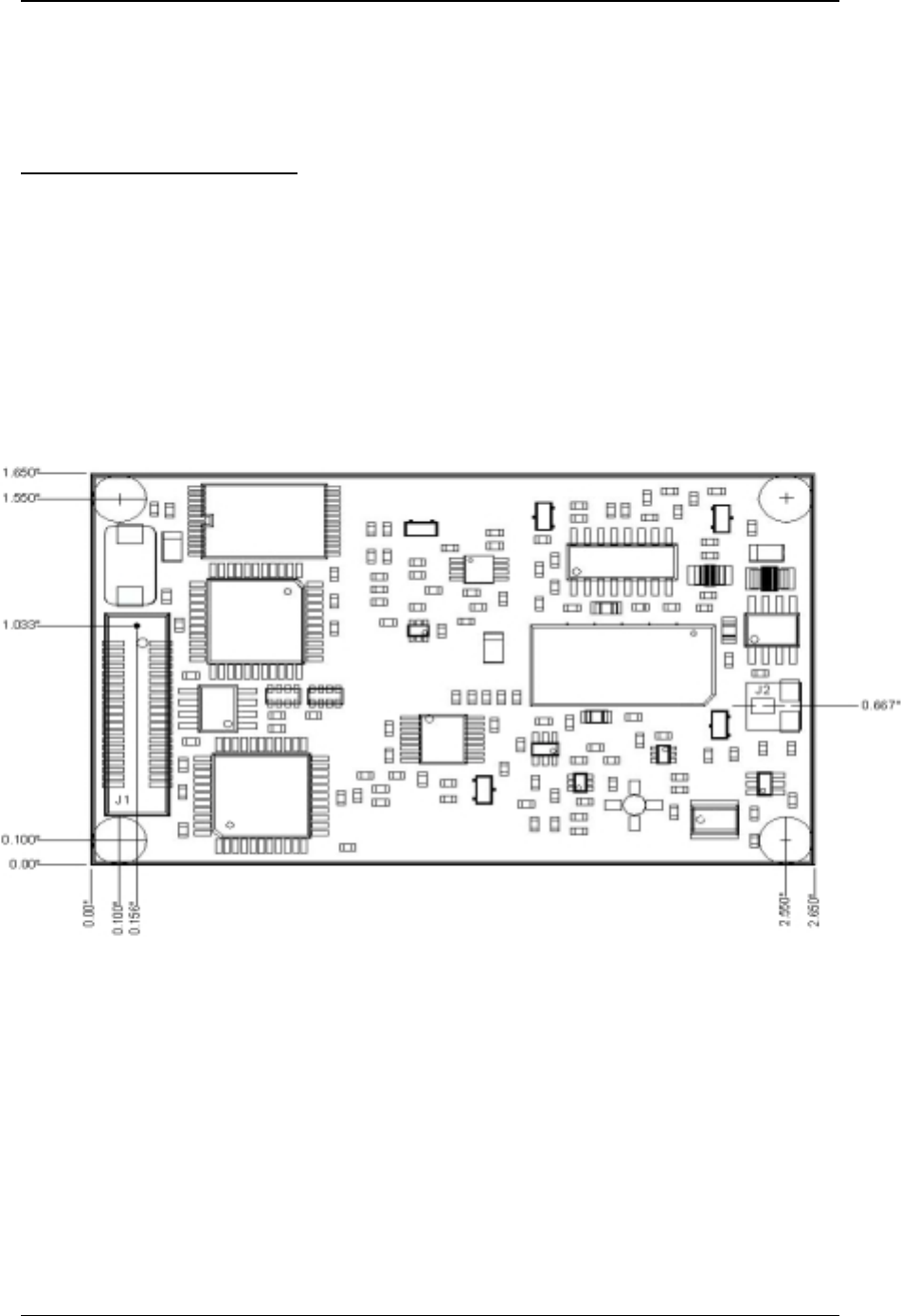
4.1 Mechanical Overview
The PKLR2400 measures 1.65” x 2.65”. Critical parameters are as follows:
J1 – 40 pin OEM interface connector (Amp P/N 177986-1) mates with Amp P/N
177985-1
J2 – High frequency MMCX style antenna connector (Huber + Suhner P/N 85-MMCX-
S50-0-51) mates with any manufacturer MMCX plug
(4) Mounting holes are 0.100” diameter.
Figure 1. Mechanical Overview of PKLR2400

Developers Kit
Preliminary 12
4.2 Pin Definitions for Connector J1
The following pinout summary is achieved through a 40 pin mini connector J1 (Amp P/N 177986-1).
Pin Serial Parallel* Definition
1 GND GND Ground
2NC NC No Connect
3VCC VCC 5V + 5%
4NC NC No Connect
5VCC VCC 5V + 5%
6NC NC No Connect
7NC NC No Connect
8NC NC No Connect
9NC NC No Connect
10 NC NC No Connect
11 NC NC No Connect
12 NC NC No Connect
13 NC D7 No Connect/Data 7
14 TXD NC Transmit/No Connect
15 NC D6 Data 6
16 RXD NC Receive/No Connect
17 NC D5 Data 5
18 NC NC No Connect
19 NC D4 Data 4
20 GND GND Ground
21 GND GND Ground
22 NC D3 No Connect/Data 3
23 CTS DIR1 Clear To Send/Bidir Handshake 1
24 Reserved Reserved Reserved Processor
25 Reserved Reserved Reserved Crystal
26 BDSEL STROBE’ Baud Select/Strobe Not
27 PKTMODE DIR2 Force API Mode 03/Bidir Handshake 2
28 NC BUSY No Connect /BUSY
29 NC NC No Connect
30 NC NC No Connect
31 NC NC No Connect
32 NC D0 No Connect/Data 0
33 NC NC No Connect
34 NC D1 No Connect/Data 1
35 NC NC No Connect
36 DCD D2 Data Carrier Detect/Data 2
37 E2WP E2WP EEPROM Write Protect
38 uP_RESET uP_RESET Microprocessor Reset
39 VCC VCC 5V + 5%
40 GND GND Ground
Note: The AeroComm radio provides 5Volt logic levels at the interface connector, J1
Note: DCD is not utilized.
Note: * Parallel interface not implemented at this time.

Developers Kit
Preliminary 13
4.3 Pin Descriptions for Connector J1
Special considerations for the hardware interface at connector, J1, are described in this section.
All remaining pin descriptions are standard for serial hardware interfaces.
4.3.1 No Connect
All No Connect pins 2, 4, 6-19, 22, 28-35 and 37 must not be connected to logic high or low
levels, but must be left floating.
4.3.2 Vcc
All Vcc pins 3, 5 and 39 require power of 5Vdc + 5% with ripple of less than 50mv p-p.
4.3.3 Clear To Send (CTS)
Clear To Send (CTS), pin 23, requires a minimum delay of 40µs between (1) and (2) after end of
each data packet.
Figure 1. Timing Note for CTS Pin
4.3.4 Reserved
The reserved pins 24 and 25 are used by AeroComm for internal testing and/or future radio
enhancements. These pins should be treated as No Connect pins and must not be connected to logic high or
low levels, but must be left floating.
4.3.5 Baud Rate Selector (BDSEL)
The Baud Rate Selector (BDSEL), pin 26, provides the user a default method of communicating
with the radio in the event the EEPROM baud rate parameters become corrupted. If pin 26 is logic high
level or not connected, the baud rate will default to the variables specified in EEPROM. If pin 26 is logic
low level, the baud rate will default to 9600 baud.
4.3.6 Forced API Mode 03 (PKTMODE)
Forced API Mode 03 (PKTMODE), pin 27, provides the user a method of programming the radio
from any of the Transparent Serial Interface Modes to the API Serial Interface Mode. It is required that
CTS
from
Radio
Delay for reply command
*Note: If level translators are
used the CTS signal will be
inverted coming from the radio.
TXD
MSB First
From Host Command Length ChecksumData
(1) (2)

Developers Kit
Preliminary 14
the radio be in API Serial Interface Mode to execute the Command Set or to configure any of the
EEPROM parameters. To force the radio into API Serial Interface Mode 03, pin 27 must be held at logic
low level and the radio reset. The radio can not be placed into any of the Transparent Serial Interface
Modes 01, 02 or 04 until pin 27 is held at logic high level and reset.
4.3.7 Microprocessor Reset (uP RESET)
Microprocessor Reset (uP RESET) is achieved by holding pin 38 at logic high level for a
minimum of 2ms. If uP RESET is performed after power has been applied to the radio and is stable, the
reset time will be significantly less. At all other times, pin 38 should be logic low level. If pin 38 is not
connected, the microprocessor will hold pin 38 at logic low level.
4.3.8 EEPROM Write Protect (E2WP)
EEPROM Write Protect (EEWP) is enabled when pin 37 is at logic high level or left floating. Pin
37 must be logic low level to Write to the EEPROM.

Developers Kit
Preliminary 15
5. Developers Kit
SDK-PKLR2400P (Parallel) and SDK-PKLR2400S (Serial) Developer Kits help system designers
implement radio designs quickly. The kit offers all the cables, power supplies, circuit schematics, documentation
and accessories needed to begin using the PKLR2400 quickly.
The kit includes:
• (2) PKLR2400 Data Radios either serial or parallel
• (2) Serial Adapter Boards with 40 pin interface, 40 pin header, LED indicators, power connector and DB9
connector. (SDK-PKLR2400S includes RS232 transceivers)
• (2) AC Power Adapters
• (2) DB9 to DB9 or (2) DB9 to DB25 for the SDK-PKLR2400S and SDK-PKLR2400P respectively
• Hardware and software interface specification
• (2) Antenna cables with patch antenna (monopole or dipole antenna optional)
• Software utilities
• Technical Support
Developers Kit
Preliminary 16
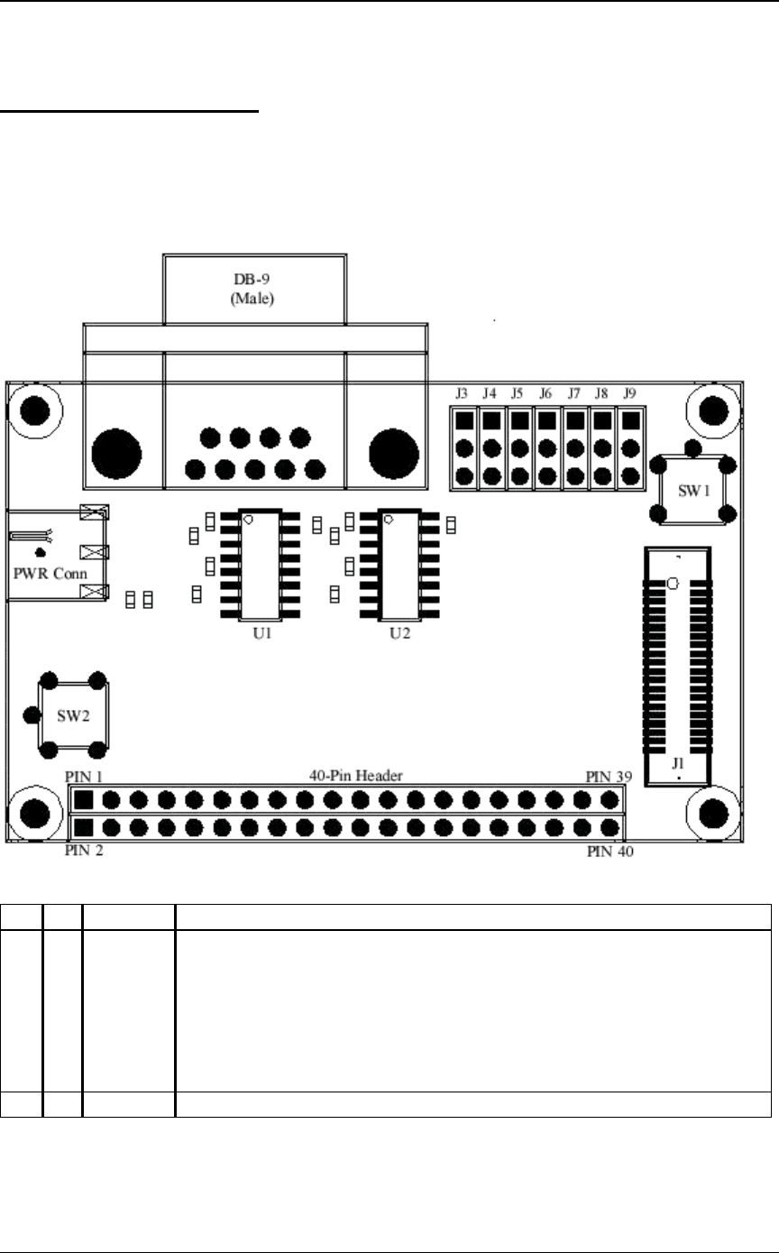
5.1 Serial Adapter Board
The Serial Adapter Board allows the use of different forms of communication with the OEM
radios. The user must choose between using RS-232 levels or 5 Volt TTL logic levels for interfacing with
the OEM radio when using the adapter board.
Figure 2. Serial Adapter Board Assembly Drawing
Item Qty Reference Description
11 J1 Amp 40 Pin Connector (177985-1) mates directly with J1 on Radio
2 1 J2 DB9 Male connector mates with provided cable to PC or OEM Host
3 1 P1 Power Connector provides power to entire kit with provided 5Vdc PS
4 2 J10 Generic 40 Pin Dip Header 0.100 Centers for test points
5 7 J3-9 Generic 3 Pin Sip Header 0.100 Centers for level translator selection
6 2 U1-2 Max202 Voltage Level Conversion Chips
7 1 SW1 SPST Switch for Reset
8 1 SW2 EEPROM Write Enable when Depressed
NOTE: The pins on the 40 pin header strip match up 1 to 1 with the pin-out of the OEM Connector
J1.
Developers Kit
Preliminary 17
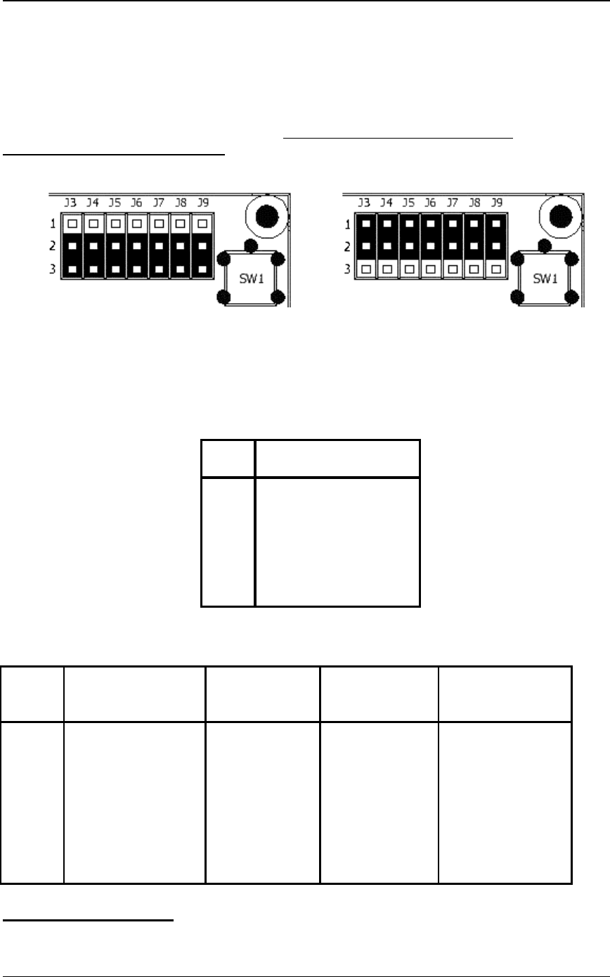
J3-J9 Level Translator Settings
If a PC will be used as the OEM server or client host, then level conversion must be enabled to
convert from the RS-232 levels at the PC to the 5 Volt TTL logic levels used on the radio. To enable level
conversion, place jumpers J3-J9 on pins 2 and 3, see Figure 3. If another device (0-5 volt TTL logic levels)
is to act as the Host for the radio then the user must disable level conversion. To disable level conversion,
place jumpers J3-J9 on pins 1 and 2 see figure 4. If running under Windows, jumper J6
(PKTMODE/RTS) must be removed.
Figure 3. Level Translation Enabled Figure 4. Level Translation Disabled
Note: If level translation is enabled it is important to note that the signal level will be inverted at the
interface connector, J1, between the OEM radio and the Serial Adapter Board.
Figure 5. Jumper Definitions.
5.1.1 Serial Adapter Board Pin Definitions
DB-9 Signal Name Associated 40-pin connector 40-Pin Header Strip
(RS-232C) Level Translation to radio Test Points
Pin # At DB-9 Connector Jumper Pin # Pin #
1 DCD not used J9 NC 35
2 RX Data J3 14 14
3 TX Data J4 16 16
4NC
5 Ground 1,20,21,40 1,20,21,40
6NC
7 PKTMODE/RTS J6 27 27
8 Clear to Send J5 23 23
9NC NC NC
5.2 Software Utilities
Jumper Associated Serial Signal
From DB-9
J3 RX Data
J4 TX Data
J5 Clear to Send
J6 PKTMODE/RTS
J7 NA
J8 NA
J9 DCD not used

Developers Kit
Preliminary 18
The developer kit includes a 3.5” diskette of software utilities allowing the customer to exercise
the radios upon receipt. The software utilities are written for a DOS environment. The software
utilities will not operate properly under a DOS shell in Windows or Windows. The software includes
several files as follows:
• OEM.EXE – Interactive Command/EE Edit Software/Transmit Receive Emulator.
• *.RTC – Script files that automate radio mode setup and demonstrates operation.
• PORTS.CFG – Com port address and baud rate information
• README.TXT – Further utility software documentation and latest release notes
• OEM.CFG – Configuration file for OEM.EXE
• OEMRWSP.INI – AeroComm Use Only
These files are located in each of three directories as follows:
1. OnePC – This directory contains all the files required to run the Client and Server radios on a single
PC. The Client Radio must be connected to Com1 (3F8) and the Server Radio must be connected to
Com 2 (2F8)
2. ClientPC- This directory contains the Client Radio files that are required to run the Client Radio on
one PC and the Server Radio on a separate PC. The Client Radio should be connected to Com 1 (3F8)
3. ServerPC- This directory contains Server Radio files that are required to run the Client Radio on one
PC and the Server Radio on a separate PC. The Server Radio should be connected to Com 1 (3F8)
5.2.1 OEM.EXE
This software contains three unique utilities to exercise, monitor and setup modes in the radios.
These utilities are: Transmit/Receive Emulator, Single Line Command Interface, and EEPROM
Viewer/Editor.
5.2.1.1 Transmit/Receive Emulator
This software allows (1) Server and (1) Client radio to communicate with each other. The
software comes pre-configured for the two radios in the development kit.
When connecting the Client and Server Radios to the same PC, connect the Server Radio to
Com 2 (2F8), then connect the Client Radio to Com 1 (3F8). Copy the OnePC directory and contents to the
PC.
When connecting the Client and Server Radios to separate PCs, connect the Server Radio to
Com 1 (3F8) on one PC, then connect the Client Radio to Com 1 (3F8) on a separate PC. Copy the
ClientPC directory and contents to the PC with the Client Radio attached. Copy the ServerPC directory and
contents to the PC with the Server Radio attached.
Note: The factory default for the Client Radio and Server Radio is API Serial Interface Mode 03.
Run OEM.EXE on one or both PCs as dictated by your setup. Press the 'F3' key to perform a
RESET and RF_Enable on all PCs. Press the 'F9' key to run the script files and demonstrate continuous
data transfers between radios. Press the 'Esc' key to stop. Pressing the 'Esc' key again will exit from the
program.
Note: The “F3” key should be used only when the radios are in API Serial Mode 03. Use “Alt R” to
perform a RESET of the radios in Transparent Serial Modes 01, 02 and 04.
While running, the screen will display transmit timeouts, receive timeouts, and run number. The
Emulator program is controlled by script files. The script files can be edited by the user and detailed

Developers Kit
Preliminary 19
instructions on how to write a script file can be found in the section below describing *.RTC. While in the
Emulator, pressing the ‘Alt’ key will bring up a window with 7 choices: File, Settings, Window, Reset,
Enable, Help and About. The File option allows the user to load a script file or execute a mode setup script
to ports 1 or 2. The Settings option allows the user to change baud rate and other settings. The Window
option allows the user to view the trace buffer or a list of the script commands. The Reset command issues a
Reset command to all ports configured in PORTS.CFG. The Enable command sends a RF_Enable to all
ports configured in PORTS.CFG.
Note: The factory default for the Client Radio and Server Radio is API Serial Interface Mode 03.
Therefore, both radios must receive an RF_enable before scripts can be run.
Note: Receive commands expecting more than 16 bytes will fail in 'F10' single-step mode.
The Transmit/Receive Emulator can also be used to execute the setup scripts provided with the
program. For a full list of the scripts, see the readme.txt file in the directory labeled ‘Scripts’ on the disk.
To execute a script, press ‘alt-F’ and then ‘Enter’ to bring up a selection window. You can enter the name
of the setup script to be run, or hit ‘Enter’ to see a list of all the available script files. It is important to note
that when you hit ‘Enter’ it will show all the script files that are in the same directory as the executable
oem.exe. Once you have a script file loaded, then you will need to depress the write protect tab on the
serial adapter board while you single step (‘F10’) through the commands in the script. Once you have
executed all the commands in the set-up script you must press the reset button on the serial adapter board
before any of the changes will be implemented.
5.2.1.2 Single Line Command Interface
While in the Transmit/Receive Emulator press the ‘F5’ key to enter into the One Line Command
Interface. The one line Command Interface allows the user to command the radios into various operation
modes. The command set has already been entered. To invoke a command, scroll to the appropriate
command, using the up/down arrows on the keyboard, until the appropriate command is highlighted. Press
the 'F10' key to send the command to the radio. Press the 'F9' key to continuously retransmit the same
command until the 'Esc' key is pressed. Press the 'F8' key to toggle between ports 1 and 2 (com1 and
com2). You will see the active port and address displayed at the top of the screen
Upon successfully receiving and executing the command, the radio will send back a acknowledge
displayed in the "Receive Data" window. At the end of each command sequence line, a highlighted
checksum is displayed. When entering a new command, it is not necessary to enter a checksum. The
program automatically calculates and enters the checksum. On exit, changes to the command interface can
either be saved or ignored. Press the 'Esc' key to exit.
5.2.1.3 EEPROM Viewer/Editor
Press the 'F2' key to enter the EEPROM viewer/editor screen. To edit a value on this screen,
simply move the cursor to highlight the appropriate value, type in the new value and press the 'Enter' key.
To undo an edit, either press the 'Esc' key to return to the Command Interface, or press any arrow key. To
update the radio with the new EEPROM values, press the 'F10' key. An EEPROM read can be performed
on this page by pressing the 'F9' key.
5.2.2 *.RTC

Developers Kit
Preliminary 20
*.RTC files contain all of the configuration information for OEM.EXE. *.RTC files can be
modified to change timeouts, ports, and commands. *.RTC files require very specific format as detailed
below:
* -- begins and ends each command sequence
T -- invoke transmit sequence over serial host/radio interface (API Mode 3)
R -- invoke receive sequence over serial host/radio interface (API Mode 3)
C -- invoke transmit sequence over serial host/radio interface (Transparent Modes 1,2,4)
S -- invoke receive sequence over serial host/radio interface (Transparent Modes 1,2,4)
D -- invoke delay
Note: Any line beginning with a "space" character is interpreted as a comment
Note: The first line in PING.RTC is always interpreted as a comment
Example Command Format
*T[transmit port number] [timeout]
[transmit port number] is either "1" or "2" as designated in PORTS.CFG
[timeout] is between "0000" and "9999" and is measured in milliseconds
[Command] [Length Low] [Length High] [Data] [Checksum automatically provided]
*
5.2.3 PORTS.CFG
Before attempting to run the executables, the user must ensure the development kit radios are
attached to the two ports specified in PORTS.CFG. The default configuration for PORTS.CFG assumes
that both developer kit radios are connected to the same computer.
The default baud rate in PORTS.CFG is 57600. This should not be changed unless the
EEPROM has been corrupted. In the event of corrupted EEPROM, hit “AltS” in the OEM.EXE program
to change the baud rate to 9600 and pin 26 on the interface connector, J1, of the radio must be logic low
level to communicate.
Note: If the EEPROM parameters for baud rate are changed, and the radio is reset, these utilities
will not communicate with the radio until pin 26 is held at logic low level and the third line of
PORTS.CFG is changed to 9600.
5.2.4 Setup Scripts
AeroComm provides several scripts to allow easy setup and configuration for different modes. These setup
scripts are as follows:
S1AC.RTC – Setup client radio to Mode 1 Addressed
S1AS.RTC – Setup server radio to Mode 1 Addressed
S1NC.RTC– Setup client radio to Mode 1 Non-Addressed
S1NS.RTC– Setup server radio to Mode 1 Non-Addressed
S2AC.RTC– Setup client radio to Mode 2 Addressed
S2AS.RTC– Setup server radio to Mode 2 Addressed
S2NC.RTC– Setup client radio to Mode 2 Non-Addressed
S2NS.RTC– Setup server radio to Mode 2 Non-Addressed
S4AC.RTC– Setup client radio to Mode 4 Addressed
S4AS.RTC– Setup server radio to Mode 4 Addressed
S4NC.RTC– Setup client radio to Mode 4 Non-Addressed

Developers Kit
Preliminary 21
S4NS.RTC– Setup server radio to Mode 4 Non-Addressed
SP3CS.RTC –This file is used to configure both the client and server radio into Mode 3 Receive mode 1
(Unicast/Broadcast).
SP3CS02.RTC – This file is used to configure both the client and server radio into Mode 3, receive mode 2
(unicast only)
SP3CS03.RTC – This file is used to configure both the client and server radio into Mode 3, receive mode 3
(Promiscuous)
In general, the filenames are defined as follows: S – Setup; X – Mode (X= mode1-4); A or N –
Addressed or Non-addressed; C or S – Client or Host. Example script name: S2NC.RTC, this would be the
setup script to set up the client radio in Mode 2, with Non-addressed broadcast mode enabled.
Also included are ping files which provide data to the radios so that out of the box, the radio’s can
be demonstrated. The included ping files are:
PINGT1B.RTC – This file is used when the radios are in Mode 1. This has big packet size just about 1K
PINGT1S.RTC – This file is used when the radios are in Mode 1. This has small packet size, < 256 Bytes
PINGT2.RTC – This file is used when the radios are in Mode 2. Has 0D as the end character
PINGT22.RTC – This file is used when the radios are in Mode 2. Has 27 as the end character.
UNICAST.RTC – This file is used when the radios are in Mode 3. As the name implies this utilizes unicast
packet structure.
BCAST.RTC – This file is used when the radios are in Mode 3. As the name implies this utilizes broadcast
packet structure.
JUNK.RTC – This is a junk packet with no accurate destination or source address, this is used to test
promiscuous mode as well as can be used to prove that such a packet is disregarded in receive
mode 1 & 2.
PINGP3B.RTC – This file is a joint packet structure to be used in Mode 1 or Mode 3. It has a broadcast
packet followed by a unicast packet.
PINGT4B.RTC – This file is used when the radios are in Mode 4. This has a big packet size..just about 1K
PINGT4S.RTC – This file is used when the radios are in Mode 4. This has a small packet size, < 256 Bytes

Developers Kit
Preliminary 22
5.3 Antenna Board
The developer kits are provided with (2) patch antennae mounted on a ground plane. In addition,
(2) SMA male to MMCX plug, cables are provided to interface the antenna boards to the radio. Optional
antennae are available for testing. Antenna selection is instrumental to and will impact overall system
performance.
5.4 Power Supply Specification
(2) power supplies are also provided to power both units in the developer kit. These supplies are
rated at regulated 5Vdc and 300ma.

Command Set
Preliminary 23
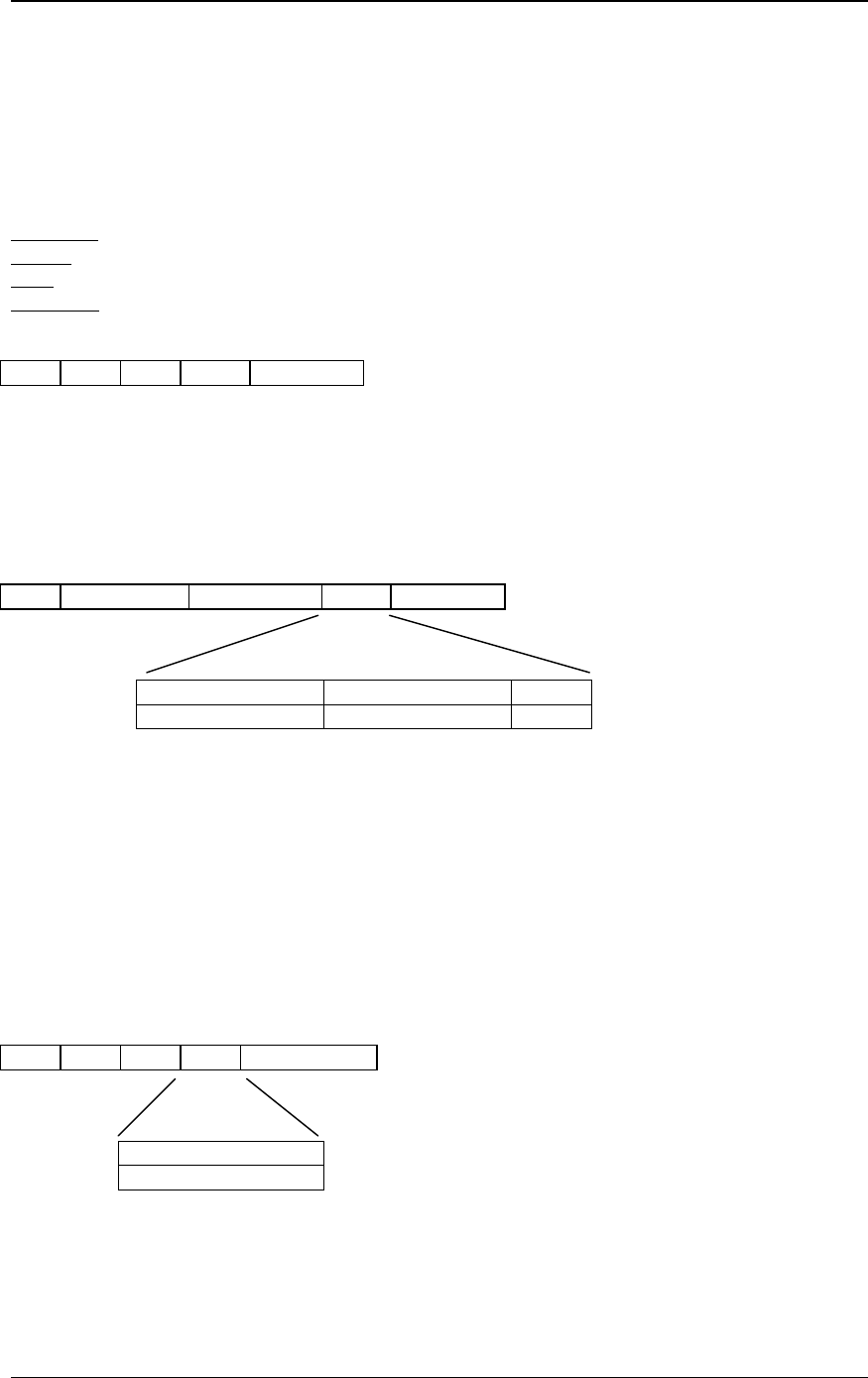
6. Command Set
The basic command set consists of several commands from the Host and Radio. The command
set can be used ONLY when the radio is in Serial Interface API Mode 03 determined by the
EEPROM address at 4AH (See Chapter 7, Configuring the PKLR2400). The command set is designed
as follows:
Command Length Data Checksum
Command -- 1 Byte. This is the actual command from the appropriate processor.
Length -- 2 Bytes. This is the total size of the remaining data for this command. The length field
is in little endian format.(i.e. low byte/hi byte). This length does not include the checksum.
Data -- N Bytes. The actual data associated with the command.
Checksum -- 1 Byte. The checksum is a byte-by-byte, bitwise “EXCLUSIVE OR” of the Data
block beginning after the Length.
6.1 System Command Set Summary
The System Commands allow the user to initialize the system and perform general system analysis
when operating in API Serial Interface Mode 03.
Name Command Length Data Checksum
Reset* AAH 0H 0H AAH
Control* 86H 1 to 5 (depends of sub command) As Required As Required
Diagnostic Result* 87H As Required As Required As Required
Standby* 88H No yet supported
Reset EEPROM* 89H 0H 0H 89H
Status Request* 8AH 1H 0-reset error counter
1-don’t do anything 8AH
Status Reply* 8BH 14H-611H See 5.1.16
Update EEPROM
Checksum* 8CH 0H 0H 8CH
Check EEPROM
Checksum* 8DH 0H 0H 8DH
EEPROM Checksum
Status* 8EH 1H 0-Checksum invalid
1-Checksum valid 8EH
Acknowledge* As Required 0H As Required
6.1.1 Reset*
This command is issued from the Host processor to the Radio. This command provides a software
reset to the PKLR2400 Radio initializing the code at the same location as a hardware reset. This must be
followed by an RF Enable.

Command Set
Preliminary 24
6.1.2 Control*
The Host processor will issue this command to Write and Read EEPROM as well as for NOP.
Sub Command one byte Description
2H* Read EEPROM. Additional data: first two bytes
specify starting address. Second two bytes specify
ending address.
8H* NOP.
9H* Write EEPROM. Additional data first two bytes
specify starting address. Second two bytes specify
ending address. Remaining bytes specify data to be
written. (Range 00 to 7F)
Data Frame:
86H Length Low 0H Data Checksum
Note: Any additional subcommands are reserved by the system and if used may cause system
operation problems.
Note: Following and EEPROM Write* Command, the user should invoke the Update EEPROM
Checksum* command.
Note: Following the EEPROM Write* Command, the user MUST invoke the Reset* command before
any EEPROM changes will become active.
6.1.3 Diagnostic result*
The Radio will issue this command upon completion of the diagnostic process.
Sub result one byte Description
2H* Read EEPROM. Additional data: first two bytes
specify starting address. Second two bytes specify
ending address.
8H* NOP. Returns 6 bytes (87 02 00 08 00 8D)
9H* Write EEPROM status. 0 - Write was successful. 1-
Write failed.
Data Frame:
87H Length Low Length High Data Checksum

Command Set
Preliminary 25
6.1.4 Standby* (THIS COMMAND NOT YET SUPPORTED)
This command is issued by the Host processor to put the Radio in one of two low power modes.
For mode 0, the Radio should disable the radio and enter a low power state. The hop synching is the only
allowed operation in this mode. For mode 1, the Radio should go into deep sleep mode. The Radio should
come out of low power modes when a command is issued from the Host processor. This command requires
an acknowledge.
Command: 88H
Length: 01H
Data: 0 - indicates low power mode, 1 - indicates sleep mode.
Data Frame:
88H 01H 00H Data Checksum
6.1.5 Reset EEPROM*
This command is sent by the OEM Host to the Radio, the result of which sets the various
locations/parameters in the EEPROM to their default values. The execution of this command does NOT
affect the IEEE Address and Operation Mode parameters in the EEPROM. This command returns a generic
positive acknowledgment.
6.1.6 Status Request*
This command is sent by the OEM Host to the Radio to find out the various statistics associated
with the RF Data Link Layer. The Radio sends back the values of the various parameters/statistics as part of
the Status Reply command. 1 byte of data is supplied along with the command that determines whether the
Radio resets the various Error Counters or not.

Command Set
Preliminary 26
6.1.7 Status Reply*
This command will be sent by the Radio to the OEM Host in response to a Status Request
command. All the different parameters pertain to the data link layer and are cumulative totals. Once this
command has been sent back to the OEM Product, depending on whether the OEM Product desired an error
counter variable reset, the reset operation is carried out. The different statistics and their sizes are shown
below:
Name Type Description Size
Radio Time Time
Counter Incremented by 1 every 250ms. Initialized to
0 at power on or reset. Unsigned Byte – 3
bytes, Low Byte
first
Tx Failures Error
Counter Number of times the Radio was not able to
deliver a data frame to the destination Unsigned Long -
4 bytes
Tx Retries Error
Counter Number of times the Radio had to retry before
delivering a data frame to the destination Unsigned Long -
4 bytes
Rx Failures Error
Counter Number of times the Radio had to throw away
a received data frame because of bad
CRC/checksum
Unsigned Long -
4 bytes
Rx Retries Error
Counter Number of times data frames had to be
retransmitted before a valid data frame was
received
Unsigned Long -
4 bytes
Num Active
Radios Data Counter Number of clients registered to a
Server Radio. If the Radio under
consideration is a Client radio, just return 0
Unsigned Byte - 1
Byte
List of
Registered
Radios
Identity A list of 6 byte IEEE Addresses of all the
radio devices + 3 byte time stamp + 3 byte
packet count. Time stamp and packet counter
are reset at power on or RESET.
12 bytes * Num
Reg Client Radios
Status Reply Example
Name Type 0 Active Radios 2 Active Radios
Radio Time Time Counter 1 Byte – TL
1 Byte – TM
1 Byte – TH
1 Byte – TL
1 Byte – TM
1 Byte – TH
Tx Failures Error Counter 4 Bytes 4 Bytes
Tx Retries Error Counter 4 Bytes 4 Bytes
Rx Failures Error Counter 4 Bytes 4 Bytes
Rx Retries Error Counter 4 Bytes 4 Bytes
Num Active Radios Data Counter 0 2
List of Registered Radios Identity 6 bytes IEEE Address
3 bytes time stamp
3 bytes packet count
6 bytes IEEE Address
3 bytes time stamp
3 bytes packet count
Checksum Actual Actual
Data Frame:
8BH 17H 00H Data Checksum

Command Set
Preliminary 27
6.1.8 Update EEPROM Checksum*
This command is sent by the Host to the AeroComm module to tell it to recalculate the checksum.
This is typically done by the Host CPU after it has completed writing data to the EEPROM on the
AeroComm module. The response to this command is an acknowledge.
6.1.9 Check EEPROM Checksum*
This command is sent by the Host CPU to the AeroComm module to validate the EEPROM
checksum. This is typically done after bringing up the AeroComm module out of reset. The AeroComm
module reports either a good or a bad checksum, by sending back a response called EEPROM Checksum
Status
6.1.10 EEPROM Checksum Status*
This command is sent by the AeroComm module in response to a Check EEPROM Checksum
command from the Host CPU. The data portion of the command indicates whether the checksum is good or
bad, based on which the Host CPU takes the appropriate action.
6.1.11 Acknowledge*
Some commands in the above set have an implied positive response. The generic positive
response is defined as the command sequence just received retransmitted back with a zero length.

Command Set
Preliminary 28
6.2 Radio Command Set Summary
The Radio Commands allow the user to control the flow of data into and out of the radio as well as
initialization of the radio in API Serial Interface Mode 03.
Name Command Length Data Checksum
RF enable* 80H 0H 0H 80H
Send Data* 81H 1 to 7f0h (includes 802.3 Header) As required As Required
Send Data Complete* 82H 1H 0 or 1 (see 5.1.4) As Required
Received Data* 83H 1 to 7f0h (includes 802.3 Header) As Required As Required
In range* 84H 06H IEEE address of
Server Radio As Required
Out of Range* 85H 0H 0H 85H
6.2.1 RF enable*
This command is issued from the Host processor to the Radio. The Radio must have this command
issued to it prior to any RF data transfers. This is a command with no data. Typically, this command is
issued to the Radio just after it has been brought out of reset. This enables the RF portion of the Radio and
turns the transmitter/receiver ON. This command requires an acknowledge.
6.2.2 Send data*
This command is issued by the Host to the Radio to send a data frame. The data frame here is the
actual frame that the transport/network protocol wants to send out. The data portion will be delivered to the
appropriate RF device. Broadcast frames will be delivered to all registered Client Radios without a RF data
link ACK. Broadcast frames are not required to reach all destinations. They are typically sent to everyone
at once.
Data Frame:
81H Length Low Length High Data Checksum
Destination Address Source Address Data
MS Byte…LS Byte MS Byte…LS Byte
Note: The Data must include header information as follows:
(6)Bytes for the IEEE 802.3 standard destination address and
(6)Bytes for the IEEE 802.3 standard source address.
These unique IEEE addresses are provided by AeroComm. See Section 4 for
EEPROM location
Note: The Length must include the IEEE 802.3 Header
Command Set
Preliminary 29
6.2.3 Send data complete*
The Radio will issue this command upon completion of the data transmission process, as indicated
by a RF-layer Acknowledgment from the destination RF-device. An additional byte of data indicates a
success or a failure code. This command must be returned for every send data command unless the device
power fails.
Command: 82H
Length: 01
Data: 0 - indicates success. 1 - Can’t send packet.
Checksum: As required
Data Frame:
82H 01H 00H Data Checksum
6.2.4 Received data*
The Radio will issue this command upon reception of data from the RF link. The information in
the data frame is the received data.
Data Frame:
83h Length Low Length High Data Checksum
Destination Address Source Address Data
MS Byte…LS Byte MS Byte…LS Byte
6.2.5 In range*
The Client Radio will issue this command upon detecting that it is in range of a Server Radio. This
command is only valid after reset or after an out of range command has been issued. This command should
have some hysterisis so that the Host processor isn’t flooded with these commands in a fringe coverage
area. The state of the RF link should be updated with the frequency specified in the Protocol EEPROM
Parameters, Chapter 7.2, to provide the needed hysterisis. This command includes the Server Radio
IEEE802 Address.
Data Frame:
84H 06H 00H Data Checksum
Server IEEE Address
MS Byte…LS Byte
Note: This is only valid from the viewpoint of Client Radio.

Command Set
Preliminary 30
6.2.6 Out of range*
The Radio will issue this command upon detecting that it is out of range of a Server Radio. This
command is only valid after reset or after an in range command has been issued to the Host processor. This
command should have some hysterisis so that the Host processor isn’t flooded with these commands in a
fringe coverage area. The state of the RF link should be updated with the frequency specified in the
configuration command to provide the needed hysterisis.
Note: This is only valid from the viewpoint of a Client Radio.

Configuring the PKLR2400
Preliminary 31
7. Configuring the PKLR2400 Radio
The various configurable parameters are stored in the EEPROM in the Radio. These parameters
are read by the AeroComm firmware on power-up reset. These parameters can be configured by
AeroComm as AeroComm defaults or customer defaults. These parameters can also be configured by the
customer using a PC and an AeroComm provided adapter. If the customer is writing to the EEPROM, they
must use the Write EEPROM Command and enable E2WP, pin 37, or switch 2 on the serial adapter board
included with the developer kit. The different configurable parameters and their respective EEPROM
locations are highlighted in this chapter.
7.1 System EEPROM Parameters
The system EEPROM parameters provide general system configuration information for the radio.
These parameters can be monitored and changed independent of the serial interface protocol. These
parameters can only be changed when the API Serial Interface Mode 03, described in Section 7.1, is
active.
EEPROM
Address Size Description
0H 40 bytes Product identifier string/Version Info
28H 6 bytes IEEE assigned MAC Address
2EH 1 byte Channel number; Range = 01- 75; Default = 00;
33H 1 byte Client/Server mode
01 – Server Radio mode
02 – Client Radio mode (default)
34H 8 bytes System ID - used to demarcate RF networks (default=00 00 00 00 00
00 00 01)
40H 1 byte Baud High (BH) – Default is FF
41H 1 byte Baud Low (BL) – Default is F7
7.1.1 Product Identifier String/Version Information
EEPROM Address: 0H
Size: 40 bytes
Useful for OEM to read AeroComm version information. This information should not be
overwritten by the OEM. Original information is restored when a RESET EEPROM command is issued.
7.1.2 IEEE assigned MAC Address
EEPROM Address: 28H
Size: 6 bytes
This is the unique, 6-byte, IEEE 802.3 ethernet address assigned by AeroComm to each radio.
This unique address should not be changed.

Configuring the PKLR2400
Preliminary 32
7.1.3 Channel Number
EEPROM Address: 2EH
Size: 1 byte
Default: 00
Range: 01-75
This provides 75 unique and non-interfering pseudorandom hopping sequences or channels. This
allows for up-to 75 independent, co-located data networks. Default shipped at 00. It is highly
recommended that this be changed to a channel number other than 00.
Note: Channel Number AND System ID between clients and server must be identical for radios to
communicate.
7.1.4 Client/Server Mode
EEPROM Address: 33H
Size: 1 byte
Default: 02
Range: 01-02
Specifies whether the radio is operating in the Client Mode (02) or Server Mode (01)
7.1.5 System ID
EEPROM Address: 31H
Size: 8 bytes
Default: 00 00 00 00 00 00 00 01
Range: 00 00 00 00 00 00 00 00 to FF FF FF FF FF FF FF FF
Note: Channel Number AND System ID between clients and server must be identical for radios to
communicate.

Configuring the PKLR2400
Preliminary 33
7.1.6 Baud High (BH) and Baud Low (BL)
EEPROM Address: 40H and 41H respectively
Size: 1 bytes
Default: FF for BH and F1 for BL
Range: 00-FF for BH and BL
Baud High (BH) along with Baud Low (BL) is used to establish the data rate over the interface
between the OEM radio and host as follows:
Sample BHBL selections for common Baud Rates
(Using a 28.224 MHz Crystal)
Baud Rate BH BL
300 F4 84
2,400 FE 91
4,800 FF 48
9,600 FF A4
19,200 FF D2
28,800 FF E1
57,600 (default) FF F1
115,200 Not Supported Not Supported
Custom baud rates can be obtained through the use of the following formula:
28.224 * 106
BAUD RATE = 32.0 * (65,536 – BH,BL)
Note: The calculated value must be within 3% of the actual value.

Configuring the PKLR2400
Preliminary 34
7.2 Protocol EEPROM Parameters
The protocol EEPROM parameters are related to the Serial Mode interface selection. A summary
of the required EEPROM settings is illustrated in Section 7.3.
Note: These parameters can only be changed when the API Serial Interface Mode 03 is active.
When in Transparent Serial Interface Modes, this can be accomplished by holding pin 27,
PKTMODE, low and resetting.
Note: When writing to EEPROM using the developer kit, remember to hold the EEPROM write
protect switch during the write command.
EEPROM
Address Size Description
2FH 1 byte Transmit data link attempts; Range = 01 - FF;
Default = 10H;
31H 1 byte Receive mode - determines what type of data frames are received by the
OEM Product, based on MAC address of received frame
01 - unicast/broadcast data (default)
02 - unicast only
03 - all (promiscuous mode)
32H 1 byte In-Range, Out-of-Range Refresh. This byte specifies the number of
250 ms ticks between range indications. This gives a range of .05
seconds to 12.5 seconds.
3EH 1 byte End Character Definition. This byte specifies the character that will be
used to signify the end of a packet.
43H 1 byte Fixed Packet Length HIGH BYTE
44H 1 byte Fixed Packet Length LOW BYTE
4AH 1 byte Serial Interface Modes
01 – Transparent, Fixed Length, with Timeout
02 – Transparent, End Character
03 – API
04 – Transparent, Fixed Length, No Timeout
4BH 1 byte Destination Address Control
00 – Addressed Mode: Destination address is the IEEE 6 bytes at 50H.
This mode utilized RF-Layer acknowledges to guarantee delivery of the
packet.
01 – Broadcast Mode: No RF-Layer acknowledge, must set Attempts
(2FH) to 01.
4DH 1 byte Interface Timeout Control
00 – 4 mS
40 – 40 mS
80 – 300 mS
C0 – 2.6 S
4EH 1 byte Broadcast Attempts; Range 01-FF; Default 04

Configuring the PKLR2400
Preliminary 35
7.2.1 Transmit Data Link Attempts
EEPROM Address: 2FH
Size: 1 byte
Default: 10H
Range: 01-FF
This parameter specifies the maximum number of attempts over the RF interface. Serial Interface
mode 03 will respond with a Send Data Failure when maximum Data Link attempts is achieved. All other
modes will not receive an acknowledge.
Note: Transmit Data Link Attempts must be set to 01 when operating in the Broadcast Mode of the
Address Transparent Control.
7.2.2 Receive mode
EEPROM Address: 31H
Size: 1 byte
Default: 01
Range: 01-03
This parameter applies only to API Serial Interface Mode 03. The default, 01, specifies
Unicast/Broadcast. Unicast will receive all packets that match the receiving unit IEEE assigned address.
Broadcast is achieved by placing FF in all six bytes of the IEEE assigned destination address sent from
sender. In Broadcast mode, the receiver will accept all data with a destination address that has FF in all six
bytes. It is important to note that there is no RF acknowledge on Broadcast packets. Mode 01 will
accept Unicast and Broadcast data packets and discard all others. In Unicast only mode, 02, The receiving
radio will receive only Unicast packets and discard all others. In Promiscuous mode, 03, the receiving radio
will accept all packets with the same System ID.
Note: The Receive Mode must be set to 03 in all Transparent Serial Interface Modes including 01, 02
and 04 at EEPROM location 4AH.
7.2.3 In-Range, Out-of-Range Refresh
EEPROM Address: 32H
Size: 1 byte
Default: 14H
Range: 01-FF
This parameter is used only when the radio is operating in API Serial Interface Mode 03. The In-
Range, Out-of-Range Refresh parameter allows the user to select the interval between which the client radio
searches for Server beacon that includes the Server IEEE source address. This parameter is very useful
when operating in a fringe condition to minimize the In-Range and Out-of-Range commands that may flood
the host. AeroComm has established a default value of 5 seconds through extensive testing.

Configuring the PKLR2400
Preliminary 36
7.2.4 End Character Definition
EEPROM Address: 3EH
Size: 1 bytes
Default: 0D
Range: 00-FF
This parameter is used only when the radio is operated in Serial Interface Mode 02 specified by
EEPROM address 4AH. Otherwise, this parameter is ignored by the system. The parameter specified by
the user will indicate the last character in a data packet. When this end character is seen by the radio, the
packet will be transmitted. The packet length including the end character can not exceed 2Kbytes.
7.2.5 Fixed Packet Length High Byte/Low Byte
EEPROM Address: 43H/44H
Size: 1 byte each
Default: 01/00
Range: 00/01 to 07/FFH
This parameter is active only when the radio is in Serial Interface Modes 01 or 04 specified by
EEPROM address 4AH. This parameter is ignored in all other modes. The fixed packet length can not
exceed 2Kbytes or it will not be received.
7.2.6 Serial Interface Modes
EEPROM Address: 4AH
Size: 1 bytes
Default: 03
Range: 01-04
There are four Serial Interface Modes for the OEM radio including one packet mode and three
transparent modes. All modes are differentiated by the definition of when data will be transmitted by the
radio.
Mode 01 specifies Transparent mode with fixed length packets and active timeout. Packets will be
transmitted over the RF interface when one of the following conditions occurs:
• The number of data bytes received over the interface is equal to the buffer specified by
the user in EEPROM address locations 43H and 44H.
• A byte gap larger the timeout specified by the user in EEPROM location 4DH occurs.
Mode 02 specifies Transparent mode with End Character. Packets will be transmitted over the RF
interface when the user-defined End Character is received by the radio over the interface. The End
Character is defined by the user at EEPROM location 3EH.
Mode 03 specifies API Mode. In this mode, the OEM has control of the radio command set
detailed in Section 6.2. Packets are buffered and transmitted at the direction of the OEM.

Configuring the PKLR2400
Preliminary 37
Mode 04 specifies Transparent mode with fixed length packets and no timeout. Packets will be
transmitted over the RF interface when the number of data bytes received over the interface is equal to the
buffer specified by the user in EEPROM address locations 43H and 44H.
Note: EEPROM parameters can not be programmed once the radios are programmed and reset in
any of the Transparent modes 01, 02 or 04. The radio must be programmed to API mode 03 to access
EEPROM parameters. This can only be accomplished by holding pin 27 low during and after reset.
7.2.7 Destination Address Control
EEPROM Address: 4BH
Size: 1 bytes
Default: 00
Range: 00-01
This parameter sets the destination address for Transparent Serial Interface modes only. The
API Serial Interface Mode 03 utilizes the Receive Mode at EEPROM address 31H to specify address
modes. With Destination Address Control set at the default, 00, the radio will determine if the six byte
IEEE address at 50H matches. If the destination address matches, the data packet is forwarded to the OEM
host. Otherwise the data is discarded. This addressed mode guarantees delivery of the data packet over the
radio link by using aknowledgements.
With Destination Address Control set to Broadcast Mode, 01, clients will receive all data packets.
There are no acknowledgements and no data packet retries in this mode.
Client radios can operate in Destination Address Control Mode 00, providing more reliable
delivery of data to the Server radio. At the same time, the Server radio can operate in Destination
Control Mode 01, acting as a broadcasting server without guaranteed delivery. This provides a
unique method of implementing a data network of many-to-one or one-to-many.
7.2.8 Interface Timeout Control
EEPROM Address: 4DH
Size: 1 bytes
Default: 00H
Range: 00, 40, 80 or C0
The Timeout parameter applies only to the Transparent Serial Interface Mode 01 with fixed length
packets and timeout. This parameter specifies the amount of time between bytes that the radio will wait
before transmitting the data packet.

Configuring the PKLR2400
Preliminary 38
7.2.9 Broadcast Attempts
EEPROM Address: 4EH
Size: 1 bytes
Default: 04H
Range: 01-FF
The Broadcast Attempt parameter applies only to the Broadcast modes for all four serial packet
modes and specifies the number of times that the RF will broadcast every packet. The receiving radio will
discard duplicate packets.
7.3 EEPROM Parameter Summary
EEPROM PARAMETERS
BY
SERIAL INTERFACE MODES
Address Description A B C D E F G H I
4AH Serial Interface Mode 01 01 02 02 03 03 03 04 04
2FH Transmit Attempts 01-FF 01 01-FF 01 01-FF 01-FF 01-FF 01-FF 01
31H Receive Mode 03 03 03 03 01 02 03 03 03
32H Range Refresh NA NA NA NA 01-FF 01-FF NA NA NA
3EH End Char Definition NA NA 00-FF 00-FF NA NA NA NA NA
43H Fixed Pkt Length-HB 01-07 01-07 NA NA NA NA NA 01-07 01-07
44H Fixed Pkt Length-LB 00-FF 00-FF NA NA NA NA NA 00-FF 00-FF
4BHDest Address Control00010001NANANA0001
4DH Interface Timeout Table Table NA NA NA NA NA NA NA
Mode Definitions
A. Mode 01 – Transparent, Fixed Length Packet, Timeout, Addressed
B. Mode 01 – Transparent, Fixed Length Packet, Timeout, Broadcast
C. Mode 02 – Transparent, End Character, Addressed
D. Mode 02 – Transparent, End Character, Broadcast
E. Mode 03 – API, Unicast/Broadcast
F. Mode 03 – API, Unicast Only
G. Mode 03 – Packet, Promiscuous
H. Mode 04 – Transparent, Fixed Length, No Timeout, Addressed
I. Mode 04 – Transparent, Fixed Length, No Timeout, Broadcast
Initializing the PKLR2400 Radio
Preliminary 39
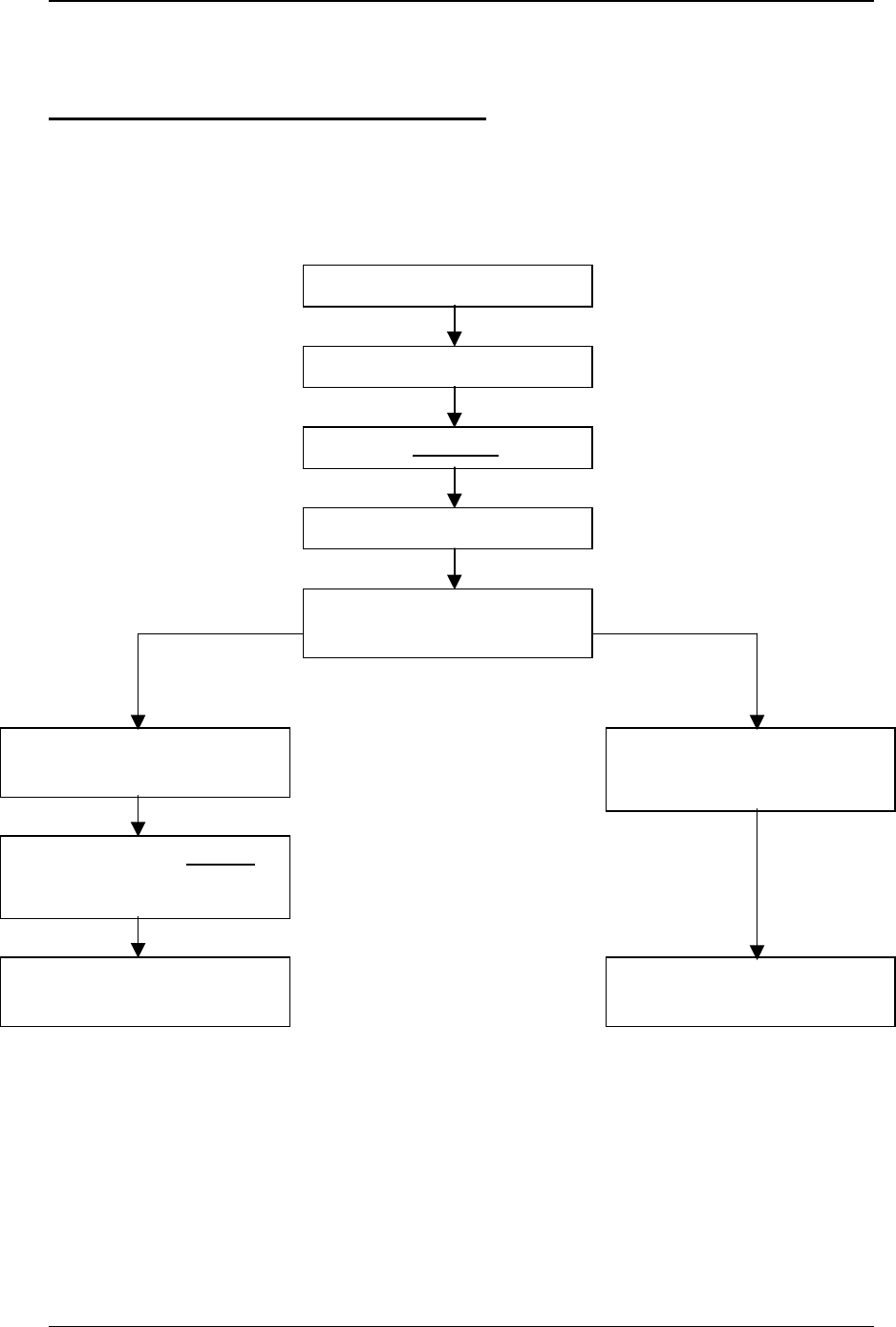
8. Initializing the PKLR2400 Radio
Following is an example of the initialization sequence for both the Client and Server Radios
following AeroComm or customer configuration of the EEPROM configuration parameters. This occurs
only in the API Serial Interface Mode 03.
Client Radio Server Radio
Apply Power
Wait for CTS logic low (if 5V)
Host issues RF enable command
Host awaits Acknowledge
Host reads EEPROM for IEEE
source address
Await Server Radio Beacon with
IEEE Server Radio address Issue Server Radio beacon every
5ms – 500ms with IEEE Server
Radio address
Client Radio issues In range
command to Host with Server
Radio address
Server Radio can now transmit or
receive data
Client Radio can now transmit or
receive data