Laird Connectivity RATESAVER Wireless Electric Meter Monitor User Manual Manual
LS Research, LLC Wireless Electric Meter Monitor Manual
Manual
LS RESEARCH
WIRELESS PRODUCT DEVELOPMENT Rate$aver IHD
1 | Page Rate$aver Datasheet (rev. 1.0) LSR -DS
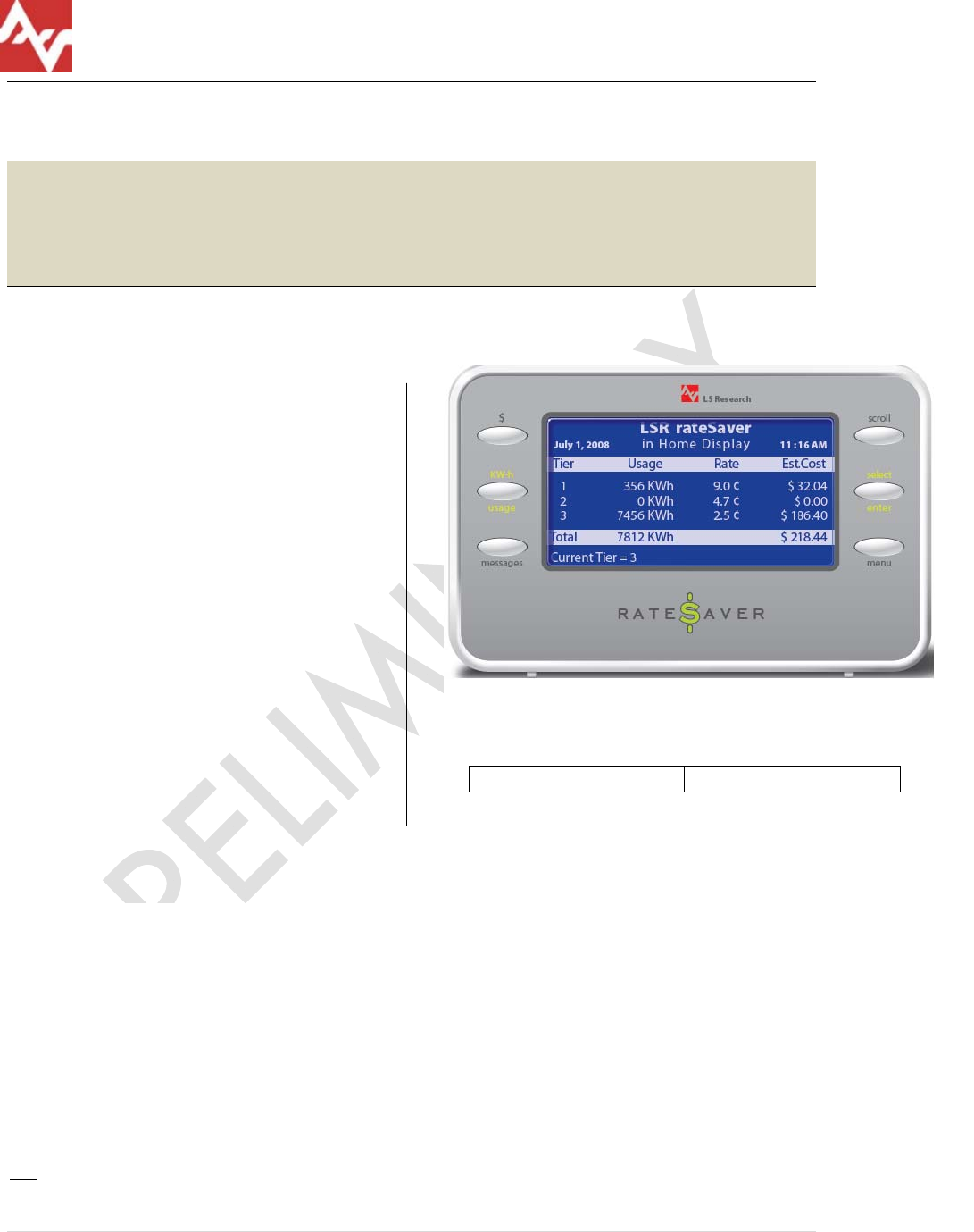
RATE$AVER
In Home Display
Features
• BATTERY OPERATED !
• Zero Power Display
• Smart Energy Profile Approved1
• Current Use / Rate / Tier Display
• Messaging / Alarm Display
• Graphical Cost and Usage
Summary
• Time-of-Use Display
• Date / Time / Temperature
• Unlimited View Angle
• 100 mW Zigbee Radio
• FCC / CE / IC Certified
(pending)2
• Simple User Interface
• Internal Buzzer / Alarm
• Optional USB Power / PC
Programming Interface
• Internal Magnet – Refrigerator
Mount
1 Pending
2 Pending
Product Description
The Rate$aver is an In-Home-Display (IHD) device capable of communicating with Smart
Energy Profile compliant Energy Service Portals (ESP) within electric meters to display
current energy consumption, utility rates, billing history, messages, alarms, temperature
and time. The device consists of display technology requiring no power consumption to
display graphical images enabling true, wireless battery operation. The device operates
on 2 AA batteries and incorporates a 100 mW high performance Zigbee radio.
Ordering Information:
Part Number RS-SE-24-01

LS RESEARCH
WIRELESS PRODUCT DEVELOPMENT Rate$aver IHD
2 | Page Rate$aver Datasheet (rev. 1.0) LSR -DS
1) Display
• 128 x 64 Pixel
• Blue / White Monochrome
• Zero Power / Persistent Display
2) Buttons
• Scroll
• Select / Enter
• Menu
• $
• kW-h usage
• Messages
3) Beeper
• Beep Tone #1: on button press – user option to disable
• Beep Tone #2: on alarm or new high priority unsolicited message – user
option to disable
• Volume – tone #1 low, tone #2 high
• Frequency: tone #1 = 500 Hz; tone #2 = 2 kHz
• Duration
o Tone #1: 100ms
o Tone #2: 500ms
4) Temperature Sensor
• Internal Temperature Sensor (Indoor Ambient Temperature Displayed)
• Range: same as product operating temperature range
• Accuracy: +/- 2 ⁰C over specified range, +/-1 ⁰C at 25 ⁰C
5) Wireless Protocol
• Conforms to Zigbee Smart Energy Profile for In Home Display device
• Supports all mandatory attributes and commands plus additional ones
required for the specified screens from the following clusters:
o Simple Metering
o Price
o Message
o Time
o Key Establishment
o Identify
o Basic
LS RESEARCH
WIRELESS PRODUCT DEVELOPMENT Rate$aver IHD
3 | Page Rate$aver Datasheet (rev. 1.0) LSR -DS
6) Supported Zigbee Cluster attributes and commands:
CLUSTER Attributes
(provided by RateSaver if a
server cluster, required from ESP
if a client cluster)
Commands Accepted Commands Generated
Basic Server ZCL version
Application Version
Stack Version
HW Version
Manufacturers Name
Model Identifier
Date Code
Power Source
Reset to Factory
Defaults
Identify Server Identify Time Identify
Identify Query
Identify Query Response
Key Establishment
Client
Key Establishment
Server
Time Client Time
Time Status
Local Time
Simple Meter Client Current Summation Delivered
Current Tier 1 Summation Del
Current Tier 2 Summation Del
Current Tier 3 Summation Del
Current Tier 4 Summation Del
Current Tier 5 Summation Del
Current Tier 6 Summation Del
Summation Formatting
Instantaneous Demand
Unit of Measure
Metering Device Type
Status (Service Disconnect,
Leak detect, Power Qual,
Power Fail, Tamper Detect, Low
Battery, Check Meter)
Others TBD
Price Client Publish Price
Get Current Price
Get Scheduled Prices
Message Client Display Message
Cancel Message
Get Last Message
Message Confirmation
Manufacturer
Specific Client
tbd
• Mandatory features
o Join network, pair devices (ZDP bind and unbind), end device
announce
o Factory defaults restore

LS RESEARCH
WIRELESS PRODUCT DEVELOPMENT Rate$aver IHD
4 | Page Rate$aver Datasheet (rev. 1.0) LSR -DS
o Enable Identify Mode by user
o Service Discovery (Match descriptor request)
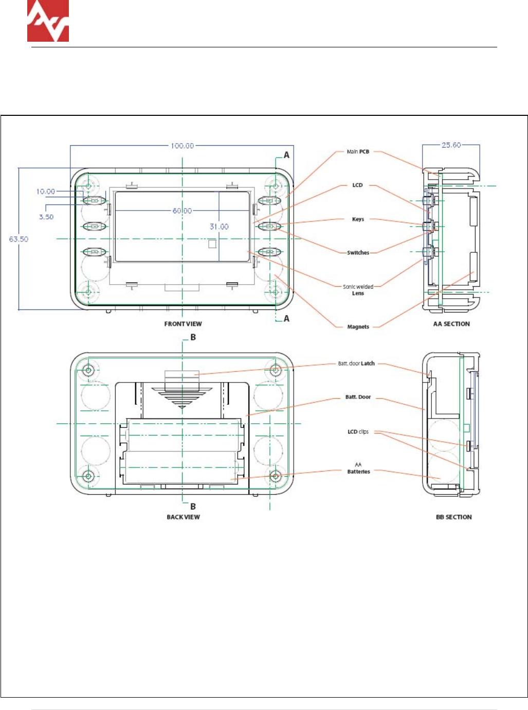
7) Enclosure
• Dimensions
o 100mm x 64mm x 26mm
• ABS Plastic
• Non-glare Lens
• Integrated Magnet for mounting
• Front Panel Label: customizable Mylar graphical overlay
8) Power supply
• Power Source
o 2 AA alkaline batteries
o USB connector power
• External Connector (for firmware upgrade)
o USB Mini-B Receptacle
• Battery Life: 1 year with 60 second update interval
• Reverse Battery Protection
9) Test and Programming Interface
• Firmware Updates: UART interface via mini-B USB connector. External
adapter required to convert USB/RS232 to UART level signals
(provided by LSR).
• Test & Debug: via JTAG Interface with access points in battery
compartment. Supports both DIP and ZIF connector interface
cables (provided by LSR).
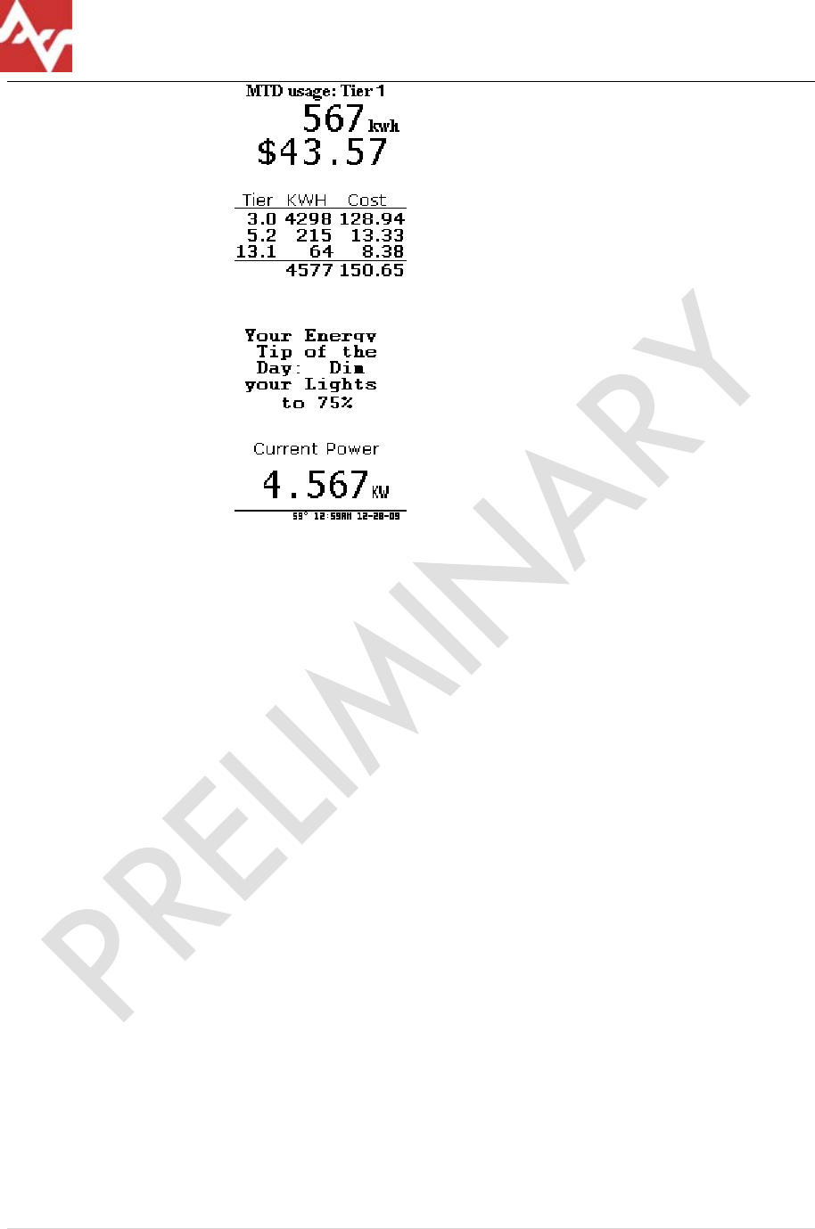
10) Screens
• Screens included as needed for particular customers. Examples include:
o Current tier, current tier rate, total consumption, total monthly bill,
standard header
o
o
o Tier breakdown screen: for each tier –horizontal bar graphs or
numeric table
LS RESEARCH
WIRELESS PRODUCT DEVELOPMENT Rate$aver IHD
5 | Page Rate$aver Datasheet (rev. 1.0) LSR -DS
o
o User Messaging Screen / Alarm Display – inverted colors-.
o Inst power screen – numeric kWatts and bar
o User Setup and Initialization
Network ID and Channel
Join Network button
Celsius/Fahrenheit
Time Zone
o Low Power: Screen Display “Replace Battery”
• Screen Operation
o Cycle through info screens on SCROLL button press
o Poll and refresh current screen on any button press
o Go to setup screen on SELECT / MENU button held for 5 seconds.
o Automatically switch to message screen when new message
received.
11) Information present on all screens (header)
• Date / Time Display
o Poll ESP no more than once per 24 hours (per SE spec)
o Accuracy within +/-1minute relative to ESP (per SE spec)
• Battery/Power Indicator
o V>= 2.0v no battery indication
o 1.6v <V<2.0v low battery icon- broken battery
o V< 1.6v unit shut down. hollow broken battery icon, no link icon, unit
off screen “Replace Battery”
• Indoor temperature
o ⁰C/⁰F user selectable
• Wireless link indicator
o Cell phone standard 4 bar antenna signal strength graphic
12) Commissioning

LS RESEARCH
WIRELESS PRODUCT DEVELOPMENT Rate$aver IHD
6 | Page Rate$aver Datasheet (rev. 1.0) LSR -DS
• user informs network owner (web login, phone call, handheld tool)
provide MAC ID and mfg supplied hashed key Utility commissions ESP to
allow join for limited time
• User / Installer press button/sequence to initiate join
• Device indicates to user “joined”
13) Polling
• Poll ESP for updated information needed for current screen:
o Immediately on screen change or refresh button press
Indicate “updating” immediately
Draw whole new screen after new info arrives, or
timeout
o Every 60 seconds on the minute
o Only changed portions of screen redraw
14) Firmware upgrades
• Wired Bootloader – through USB connector
• Wireless Bootloader – must be implemented in ESP or parent router
to the display. Requires code to initiate the bootloader in the
display and transfer the code image. Also method to read/supply
the code image file. LSR to supply example source code and
specifications.
15) Regulatory Requirements (pending)
• FCC part 15.247, 15.209
• Industry Canada RSS 210
• CE EN 300 220 1
• C-Tick
• Zigbee SE Profile Certification
• RoHS Compliant
16) Environmental
• Operating temperature
o 10deg C to 70deg C
• Storage temperature
o -20deg C to 100deg C
• Relative Humidity – non-condensing
o <90% for T<40C, <50% T>40C
• Physical shock (consumer level drop test)
o Test per IEC 60068-2-27 (Shock)
o 20g peak acceleration in three orthogonal axis
o Saw tooth pulse shape, 11ms pulse width
• Vibration
o Test per IEC 60068-2-6 (Sinusoidal Vibration)

LS RESEARCH
WIRELESS PRODUCT DEVELOPMENT Rate$aver IHD
7 | Page Rate$aver Datasheet (rev. 1.0) LSR -DS
o 5g-peak acceleration
o 10-150 Hz
o Five cycles per axis in three orthogonal axis
• ESD
o Per CE approval limits specified in ETS 301-489 and EN 61000-4-2
testing methods
LS RESEARCH
WIRELESS PRODUCT DEVELOPMENT Rate$aver IHD
8 | Page Rate$aver Datasheet (rev. 1.0) LSR -DS
Absolute Maximum Ratings
Rating Value Unit
Power Supply Voltage Input 3.5 Vdc
Voltage on any digital pin Max 3.6 Vdc
RF Input Power +10 dBm
Storage Temperature Range
-45 to 125 ºC
Note: Under no circumstances exceeding the maximum ratings in Table can be allowed. Such
a stress may cause permanent damage to the devices
Operating Conditions
Characteristic Min Typ
Max
Unit
Power Supply Voltage (Vdd) 2.1 3.5 V
Input Frequency 2405
2480
MHz
Ambient Temperature Range
10 25 70 ºC
Logic Input Low Voltage 0 0.7 V
Logic Input High Voltage 2.8 3.6 V
Radio Electrical Specifications
At 25ºC, Vdd = 3.3V for both APEX and APEX LT unless stated otherwise.
General
Parameter Min Typ
Max Unit
RF Frequency Range 2400
2483.5 MHz
RF Data Rate 250
kbps
Microcontroller Operating Frequency
12 MHz
Flash Memory 128
kB
RAM 5 kB
Power Consumption
Parameter Min
Typ
Max
Unit
Transmit Mode (100mW output)
Receive Mode
Standby Mode
Boost mode is an optional higher performance radio mode that is software selectable to boost
receiver sensitivity.
Transmitter
Parameter Min
Typ
Max
Unit
Nominal Output Power 20 dBm
LS RESEARCH
WIRELESS PRODUCT DEVELOPMENT Rate$aver IHD
9 | Page Rate$aver Datasheet (rev. 1.0) LSR -DS
Programmable Output Power range
32 dB
Error Vector Magnitude 15 35 %
Receiver
Parameter Min
Typ
Max Unit
Receiver Sensitivity (1% PER) – normal mode
-92 -96 dBm
Receiver Sensitivity (1% PER) – boost mode -93 -97 dBm
Saturation (Maximum Input Level) (1% PER) 0 dBm
802.15.4 Adjacent Channel Rejection
APEX
35 dB
802.15.4 Alternate Channel Rejection 40 dB
802.11g Rejection (±10 MHz)
APEX
40 dB
Control DC characteristics
Parameter Min Typ
Max Unit
Logic Input Low 0 0.2VDD V
Logic Input High 0.8VDD VDD V
Logic Output Low 0 0.18VDD V
Logic Output High 0.82VDD
VDD V
Output source current 4 mA
Output sink current 4 mA
Output source current 8 mA
Output sink current 8 mA
I/O pin pull-up and pull-down resistor
30 kΩ
Figure 1
LS RESEARCH
WIRELESS PRODUCT DEVELOPMENT Rate$aver IHD
10 | Page Rate$aver Datasheet (rev. 1.0) LSR -DS
Mechanical Drawing

LS RESEARCH
WIRELESS PRODUCT DEVELOPMENT Rate$aver IHD
11 | Page Rate$aver Datasheet (rev. 1.0) LSR -DS
Disclaimer
LS Research, LLC believes the information in this document is correct and
accurate at the time of release. However, LS Research, LLC reserves the right
to make changes to this product without notice.
Statements
Compliance Statement (Part 15.19)
This device complies with Part 15 of the FCC Rules.
Operation is subject to the following two conditions:
1. This device may not cause harmful interference, and
2. This device must accept any interference received,
including interference that may cause undesired operation.
Warning (Part 15.21)
Changes or modifications not expressly approved by the party
responsible for compliance could void the user’s authority to
operate the equipment.
FCC Interference Statement (Part 15.105 (b))
This equipment has been tested and found to comply with the limits for a
Class B digital device, pursuant to Part 15 of the FCC Rules. These limits are
designed to provide reasonable protection against harmful interference in a
residential installation. This equipment generates uses and can radiate radio
frequency energy and, if not installed and used in accordance with the
instructions, may cause harmful interference to radio communications.
However, there is no guarantee that interference will not occur in a particular
installation. If this equipment does cause harmful interference to radio or
television reception, which can be determined by turning the equipment off
and on, the user is encouraged to try to correct the interference by one of
the following measures:
- Reorient or relocate the receiving antenna.
- Increase the separation between the equipment and receiver.
- Connect the equipment into an outlet on a circuit different from that
to which the receiver is connected.
- Consult the dealer or an experienced radio/TV technician for help.

LS RESEARCH
WIRELESS PRODUCT DEVELOPMENT Rate$aver IHD
12 | Page Rate$aver Datasheet (rev. 1.0) LSR -DS
RF Exposure (OET Bulletin 65)
To comply with FCC’s and IC’s RF exposure limits for general population /
uncontrolled exposure, the antenna(s) used for this transmitter must be
installed to provide a separation distance of at least 20 cm from all persons
and must not be co-located or operating in conjunction with any other
antenna or transmitter.
Section 7.1.5 of RSS-GEN
Operation is subject to the following two conditions:
1) This device may not cause harmful interference, and
2) This device must accept any interference received,
including interference that may cause undesired operation.