Laird Connectivity TIWI1-01 TIWI TRANSCEIVER MODULE User Manual TiWi UG 01 V2x
LS Research, LLC TIWI TRANSCEIVER MODULE TiWi UG 01 V2x
UserManual.wiki
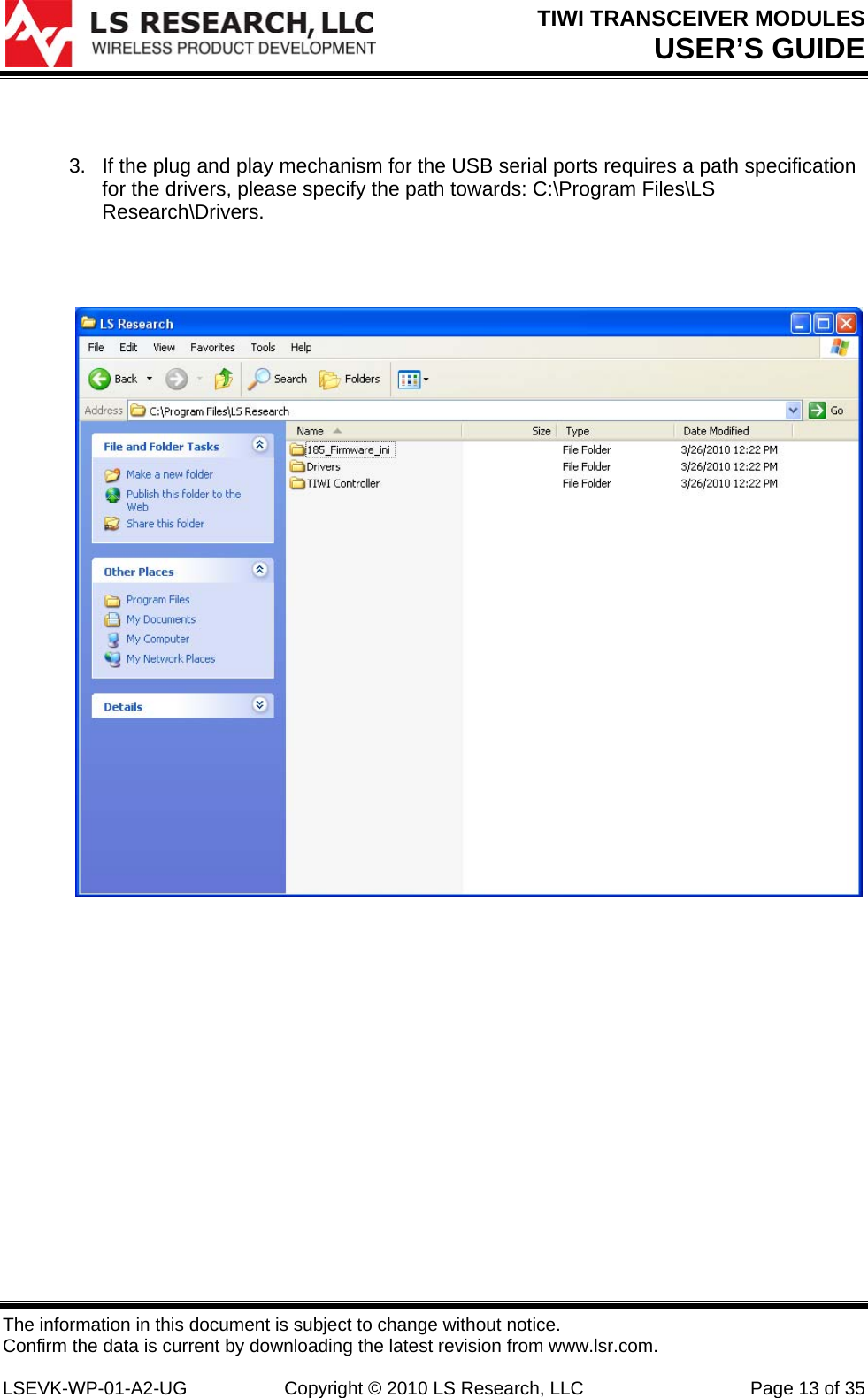
>
Laird Connectivity
>
TIWI1-01 User Manual
>
Manual
Contents
1.
Manual
2.
BLE model manual
3.
R2 model manual
4.
User manual 1 of 2
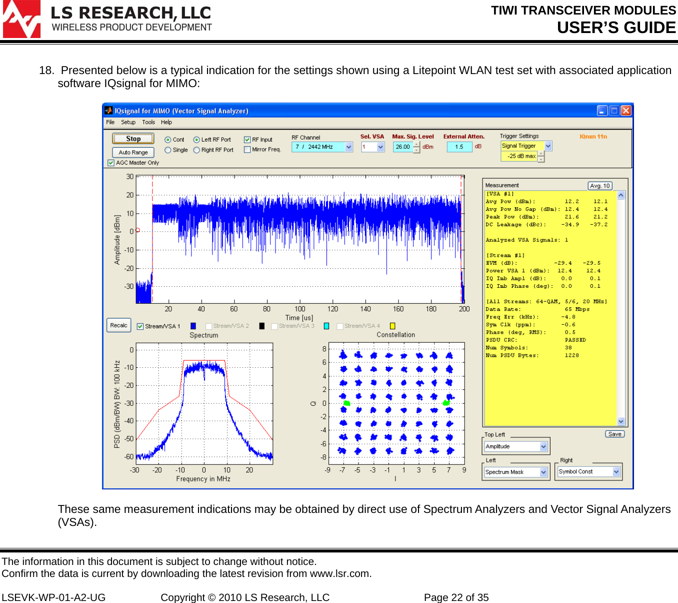
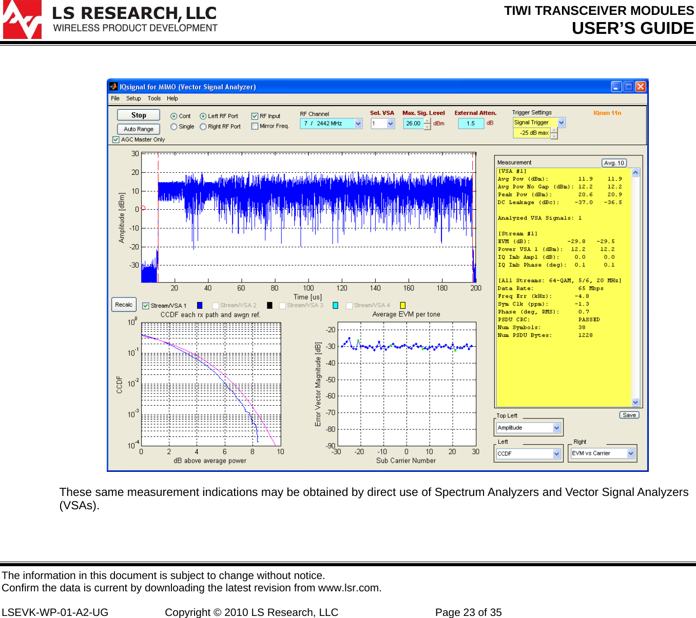
5.
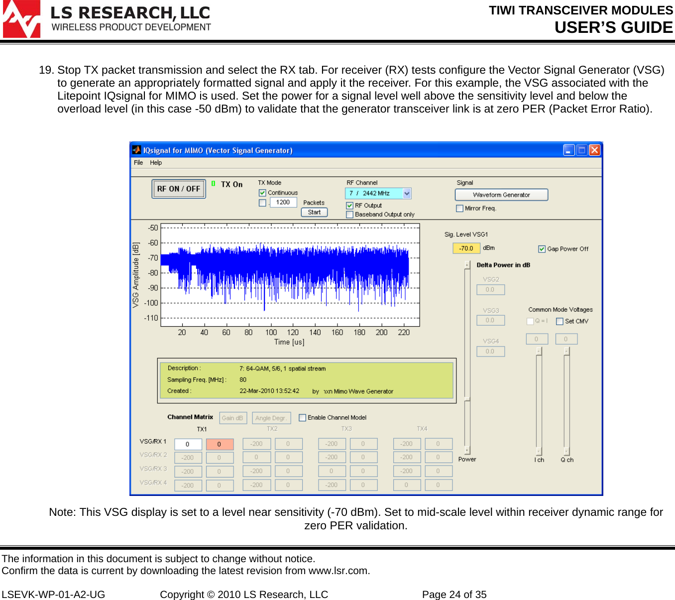
User manual 2 of 2
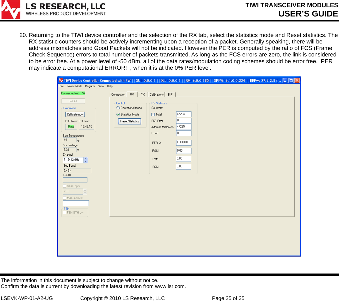
Manual
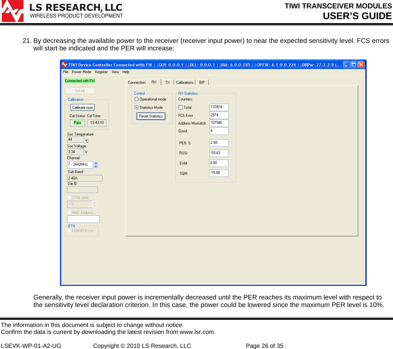
Navigation menu
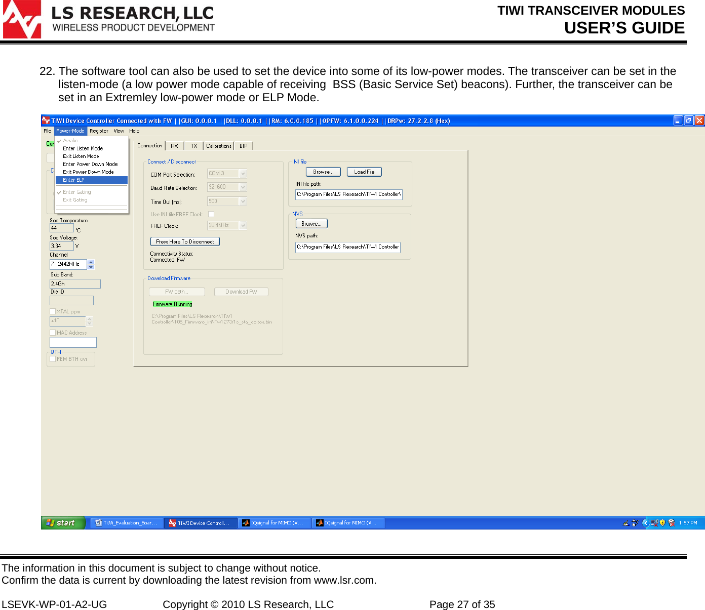
Upload a User Manual
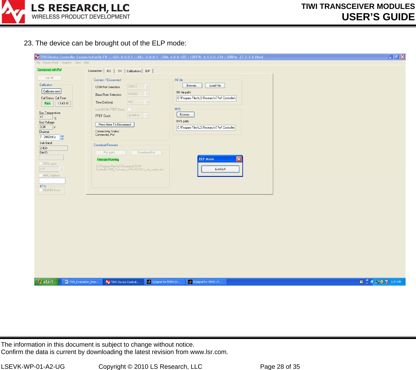
Namespaces
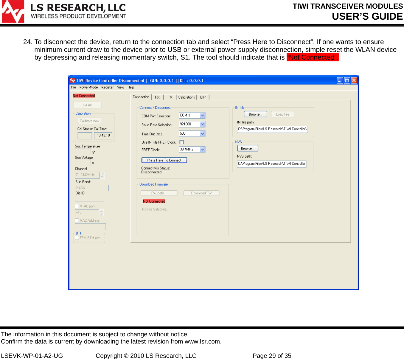
Wiki Guide
HTML
PDF
Info
Views
User Manual
Discussion / Help
Navigation
![TIWI TRANSCEIVER MODULES USER’S GUIDE The information in this document is subject to change without notice. Confirm the data is current by downloading the latest revision from www.lsr.com. LSEVK-WP-01-A2-UG Copyright © 2010 LS Research, LLC Page 3 of 35 1 Introduction 1.1 Purpose & Scope The purpose of this document is to provide details regarding the setup and use of the TiWi series transceiver module within its companion evaluation board. This document covers a description of the evaluation board and its features and a brief tutorial on how to operate the module evaluation board. Further, this document will also present application guidance such that the module’s EMC compliance will not be degraded. 1.2 Audience This document is intended to be read by engineers and technical management. A general knowledge of common engineering practices is assumed. 1.3 Applicable Documents • [1] TiWi Datasheet- LS240-WI-01-A20 (LSR) • [2 ]FCC Test Report # 310117, LS Research, LLC: September 8,2010 • [3] SAR Test Report: FCC ID: TFB-TiWi1-01, RF Exposure Lab, San Marcos, CA: September, 2010. • [4] Evaluation Board Schematics • [5] Ethertronics Presetta 1000423 Antenna Data Sheet. • [6] LSR 001-0001 Dipole Antenna Data Sheet. • [7] FCC OET Bulletin 62, “UNDERSTANDING THE FCC REGULATIONS • FOR COMPUTERS AND OTHER DIGITAL DEVICES”, February 1996. 1.4 Revision History Date Change Description Revision 10/8/2010 Initial release. 0.0 Table 1 Revision History](https://usermanual.wiki/Laird-Connectivity/TIWI1-01.Manual/User-Guide-1388427-Page-3.png)
![TIWI TRANSCEIVER MODULES USER’S GUIDE The information in this document is subject to change without notice. Confirm the data is current by downloading the latest revision from www.lsr.com. LSEVK-WP-01-A2-UG Copyright © 2010 LS Research, LLC Page 9 of 35 12345 Figure 2 TiWi Evaluation Board, LSEVK-WI-01-A20: Jumper positions(Name)[Selection Options]: 1. Select power source (PWR SOURCE),[DC,WL,BT], 2. Select VIO source (VIO SOURCE),[EXT,BOARD] 3. Select VBAT Source (VBAT SOURCE),[EXT,BOARD]. 4. BT reset (holds BT function in reset). 5. FM reset (holds FM in reset).](https://usermanual.wiki/Laird-Connectivity/TIWI1-01.Manual/User-Guide-1388427-Page-9.png)
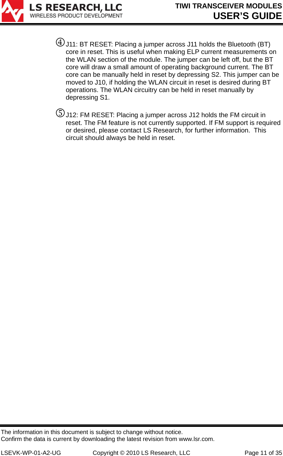
![TIWI TRANSCEIVER MODULES USER’S GUIDE The information in this document is subject to change without notice. Confirm the data is current by downloading the latest revision from www.lsr.com. LSEVK-WP-01-A2-UG Copyright © 2010 LS Research, LLC Page 10 of 35 3. The jumper positions shown as blue rectangles correspond to the following primary power supply options: 1 J19: PWR SOURCE: The input + 5VDC primary supply voltage for the interface circuit power supplies and board-derived module power supplies can be selected from 3 different sources. • PWR: Apply + 5 VDC to J7 (5V IN). • WL: Connect to USB + 5 VDC pin, voltage sourced from WLAN USB port (J5). • WL: Connect to USB + 5 VDC pin, voltage sourced from BT USB port (J6). 2 J8: VIO SOURCE: The input + 1.8VDC primary supply for the digital interface circuitry on the module, can be supplied externally (TM1) or from a regulated 1.8 VDC supply on the board (derived from + 5 VDC input voltage [USB or external]. • BOARD: Route board-derived 1.8 VDC power supply to module VIO input. • EXT: Supply 1.8 VDC power supply to module VIO from external power supply, e.g. lab supply. 3 J9: VBAT SOURCE: The input + 3.6VDC primary supply for the main analog suppl on the module, can be supplied externally (TM2) or from a regulated 3.3 VDC supply on the board (derived from + 5 VDC input voltage [USB or external]. • BOARD: Route board-derived 3.6 VDC power supply to module VBAT input. • EXT: Supply 3. 6 VDC (nominal) power supply to module VBAT from external power supply, e.g. lab supply.](https://usermanual.wiki/Laird-Connectivity/TIWI1-01.Manual/User-Guide-1388427-Page-10.png)

![TIWI TRANSCEIVER MODULES USER’S GUIDE The information in this document is subject to change without notice. Confirm the data is current by downloading the latest revision from www.lsr.com. LSEVK-WP-01-A2-UG Copyright © 2010 LS Research, LLC Page 31 of 35 3 EMC Compliance Application Guide 3.1 Introduction The TiWi module has been tested as Modular Radio in accordance with the FCC [].The device has been tested to relevant FCC parts and the results of the testing may be found in the module’s test report [2]. Since this module and its associated set of approved antenna has been certified as a Modular Radio, this allows the end user to integrate this module into an end-product and only be responsible for the Unintentional Emissions levels produced by the product. The manufacturer of the module is the responsible for the compliance of the Intentional Emissions produced by the module, as long as, the recommendations presented in this application guide. 3.2 Module Integration Considerations – Antenna Systems the module must be used with one of the approved antennas: LS Research 001-0001 with LS Research U.FL to Reverse Polarity SMA conector cable (LS Research 080-0001). 1. Ethertronics Presetta 1000423 and Johnson Emerson U.FL. to U.FL coaxial cable 415-0088-150. The antennas should placed such that they are minimally disturbed by the product’s packaging material. The incorporation of the largest practical free-space clearance around the antenna is important for maximizing overall performance. The clearances associated with the SAR compliance must be maintained. 3.3 Module Integration Considerations – Circuit Implementation The module should be integrated according to either the application circuit found in the device data sheet or in accordance with the circuit provided for the evaluation board, along with best engineering practices to minimize unintentional EMC emissions. It is recommended that all connection PCB (printed circuit board) traces to the power supply and digital control terminal be as short as possible. Though not necessarily required in all cases, it is a best practice to provide an optional shunt capacitor placement at the module pin on all active and routed power supply and digital control lines. Further, a series damping resistor placement should be incorporated between the module pin/shunt capacitor node and the source/sink of the digital control signals. This provides for effective bypassing and decoupling of digital lines from the radio module, in the event that the application circuit has longer power supply and digital routing.](https://usermanual.wiki/Laird-Connectivity/TIWI1-01.Manual/User-Guide-1388427-Page-31.png)
![TIWI TRANSCEIVER MODULES USER’S GUIDE The information in this document is subject to change without notice. Confirm the data is current by downloading the latest revision from www.lsr.com. LSEVK-WP-01-A2-UG Copyright © 2010 LS Research, LLC Page 32 of 35 3.4 Module Integration Considerations - Top Assembly Considerations. In addition to the recommendations given for the antenna systems and the module placement onto a product PCB, it is recommended that all wiring and interconnect systems within the product be not routed anywhere close the module and its associated circuitry on the PCB, doing so could change the emission characteristics of the module. 3.5 Module Integration Considerations – Firmware The module must use the specific operational firmware provided by LSR for the module. This firmware includes: 1. Binary image: FW1273r1c_sta_cortex.bin (version 185). 2. ini.ini. configuration file. 3.6 Testing Requirements for End-Product Once the module is integrated and the product realized, the product must be tested and follow the verification process for Unintentional Conducted and Radiated Emissions in accordance to the FCC guidelines [7]. The module is to be placed in the receive mode for this test (see step 20). 3.7 Marking Requirements for End-Product and Compliance Statements. Federal Communication Commission Interference Statement This equipment has been tested and found to comply with the limits for a Class B digital device, pursuant to Part 15 of the FCC Rules. These limits are designed to provide reasonable protection against harmful interference in a residential installation. This equipment generates uses and can radiate radio frequency energy and, if not installed and used in accordance with the instructions, may cause harmful interference to radio communications. However, there is no guarantee that interference will not occur in a particular installation. If this equipment does cause harmful interference to radio or television reception, which can be determined by turning the equipment off and on, the user is encouraged to try to correct the interference by one of the following measures: - Reorient or relocate the receiving antenna. - Increase the separation between the equipment and receiver. - Connect the equipment into an outlet on a circuit different from that to which the receiver is connected. - Consult the dealer or an experienced radio/TV technician for help.](https://usermanual.wiki/Laird-Connectivity/TIWI1-01.Manual/User-Guide-1388427-Page-32.png)