Laird Connectivity TIWI1-01 TIWI TRANSCEIVER MODULE User Manual OneExpert DSL User s Guide
LS Research, LLC TIWI TRANSCEIVER MODULE OneExpert DSL User s Guide
Contents
- 1. Manual
- 2. BLE model manual
- 3. R2 model manual
- 4. User manual 1 of 2
- 5. User manual 2 of 2
User manual 1 of 2

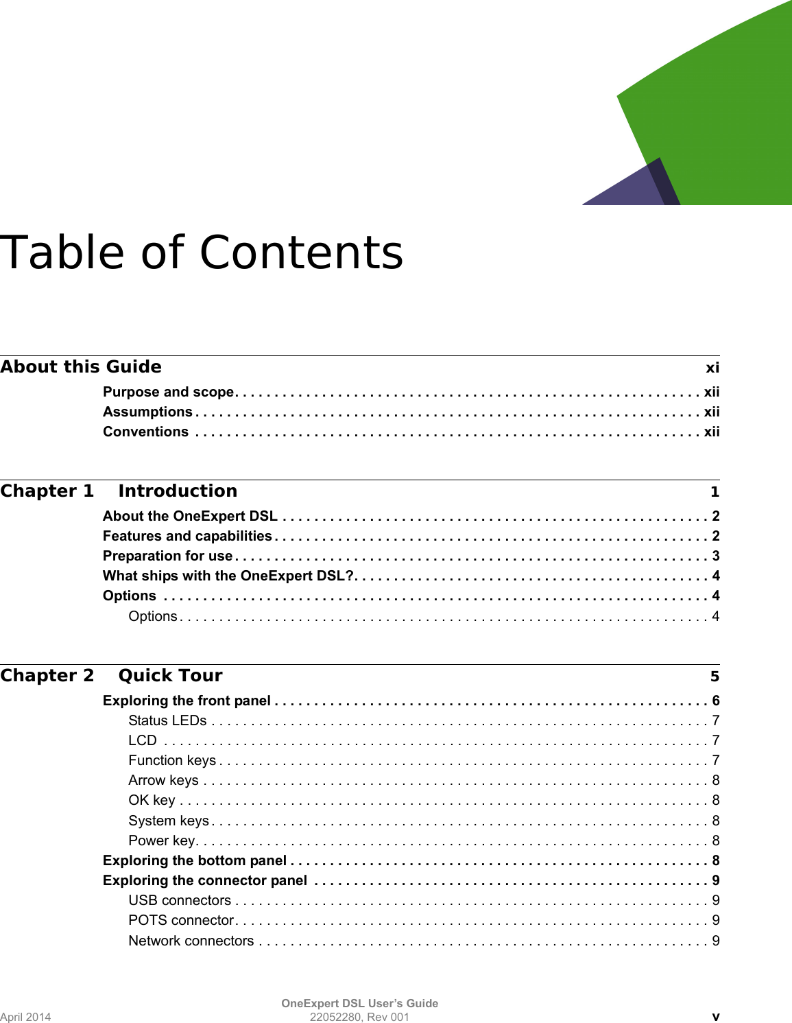

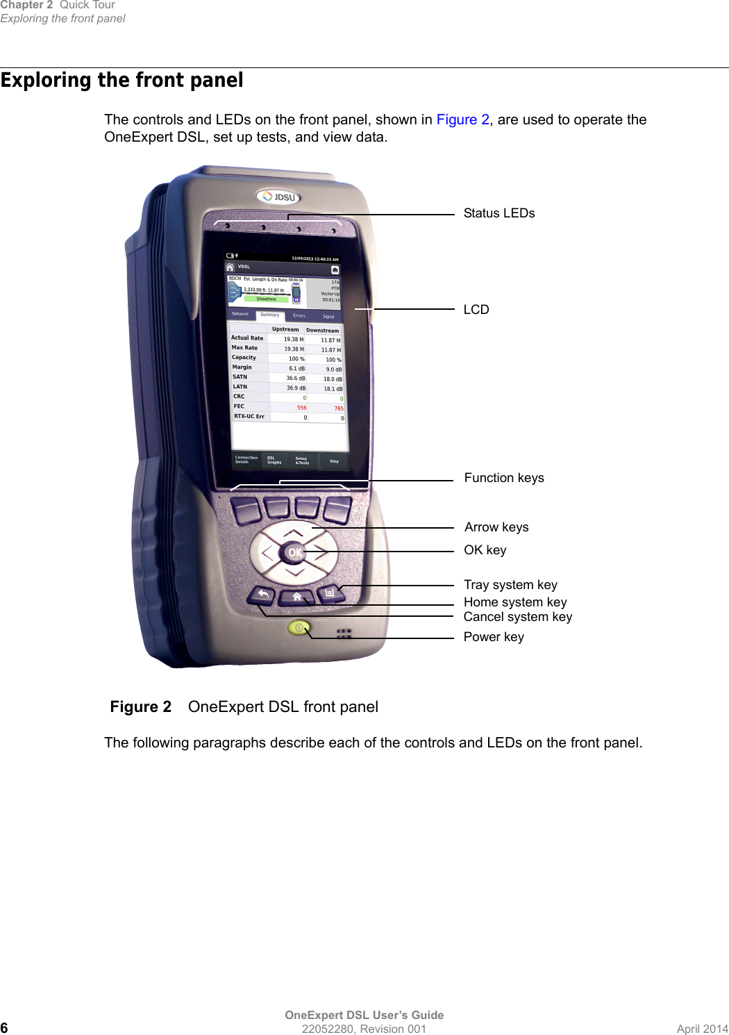
![About this GuidePurpose and scopeOneExpert DSL User’s Guidexii 22052280, Rev 000 April 2014Purpose and scopeThe purpose of this guide is to help you successfully use the features and capabilities of the OneExpert DSL. This guide includes task-based instructions that describe how to configure, use, and troubleshoot the general functions of the OneExpert DSL. Additionally, this guide provides a description of JDSU’s warranty. For terms and conditions of the licensing agreement, go to www.jdsu.com.AssumptionsThis guide is intended for novice, intermediate, and experienced users who want to use the OneExpert DSL effectively and efficiently. We are assuming that you have basic computer experi-ence and are familiar with basic telecommunication concepts, terminology, and safety.ConventionsThe symbols and safety terms used in this guide are described in the following tables.NOTE:For information about CE compliance, see the Declaration of Conformity or contact your local JDSU representative. A copy of the declaration is included in the shipping package. Table 1 Typographical conventionsDescription ExampleUser interface actions appear in this typeface. On the Status bar, click Start.Buttons or switches that you press on a unit appear in this TYPEFACE.Press the ON switch.Code and output messages appear in this typeface.All results okayText you must type exactly as shown appears in this typeface.Type: a:\set.exe in the dialog box Variables appear in this typeface. Type the new hostname.Book references appear in this typeface. Refer to Newton’s Telecom DictionaryA vertical bar | means “or”: only one option can appear in a single command. platform [a|b|e]Square brackets [ ] indicate an optional argument. login [platform name]Slanted brackets < > group required arguments. <password>](https://usermanual.wiki/Laird-Connectivity/TIWI1-01.User-manual-1-of-2/User-Guide-2244588-Page-14.png)

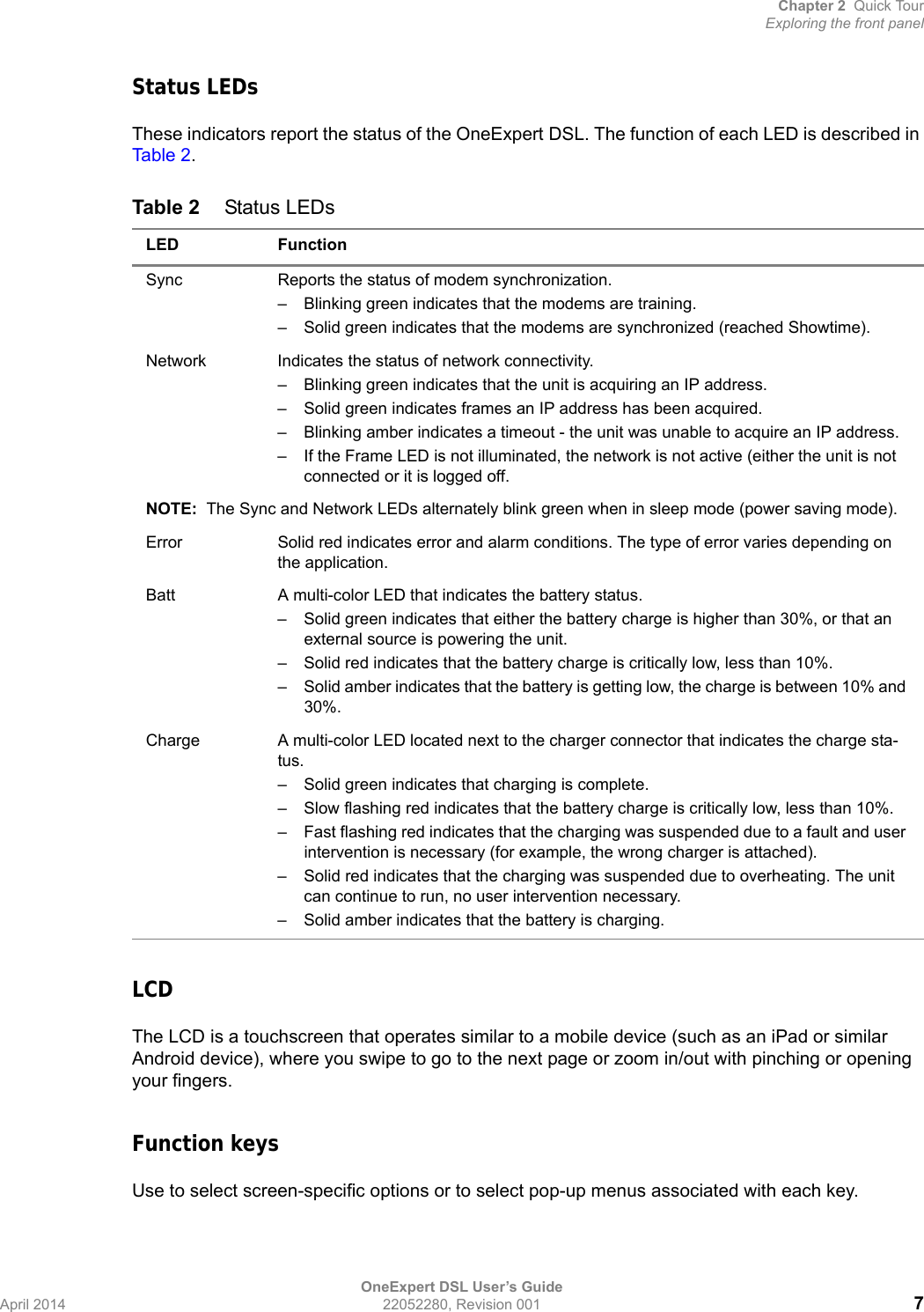

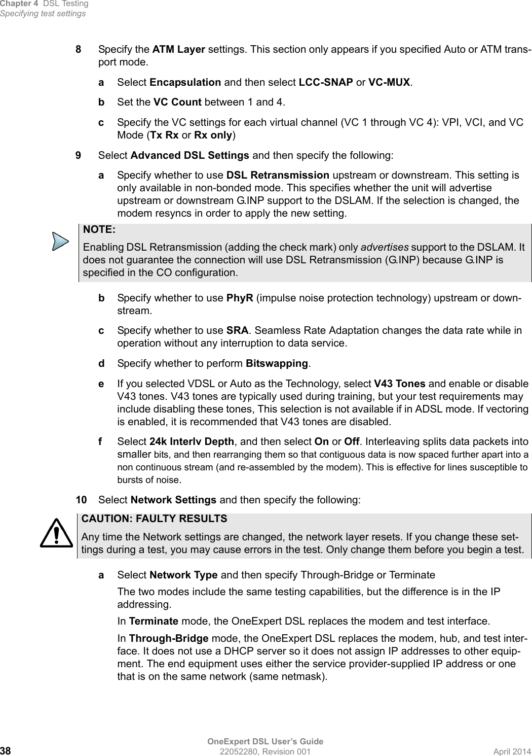

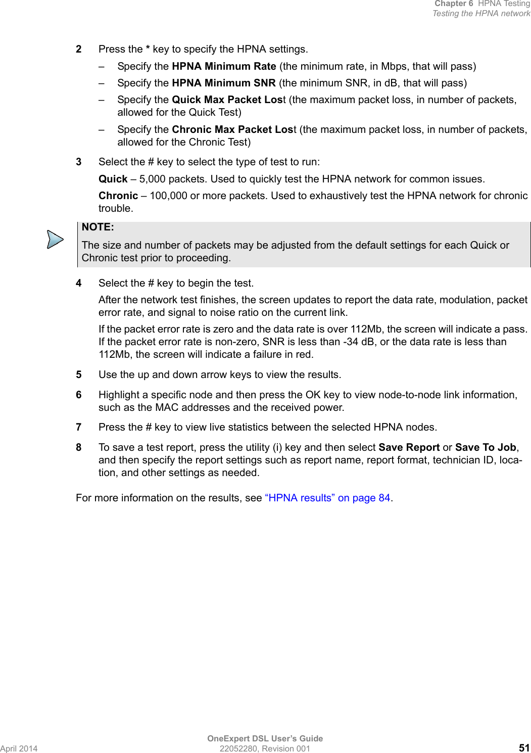


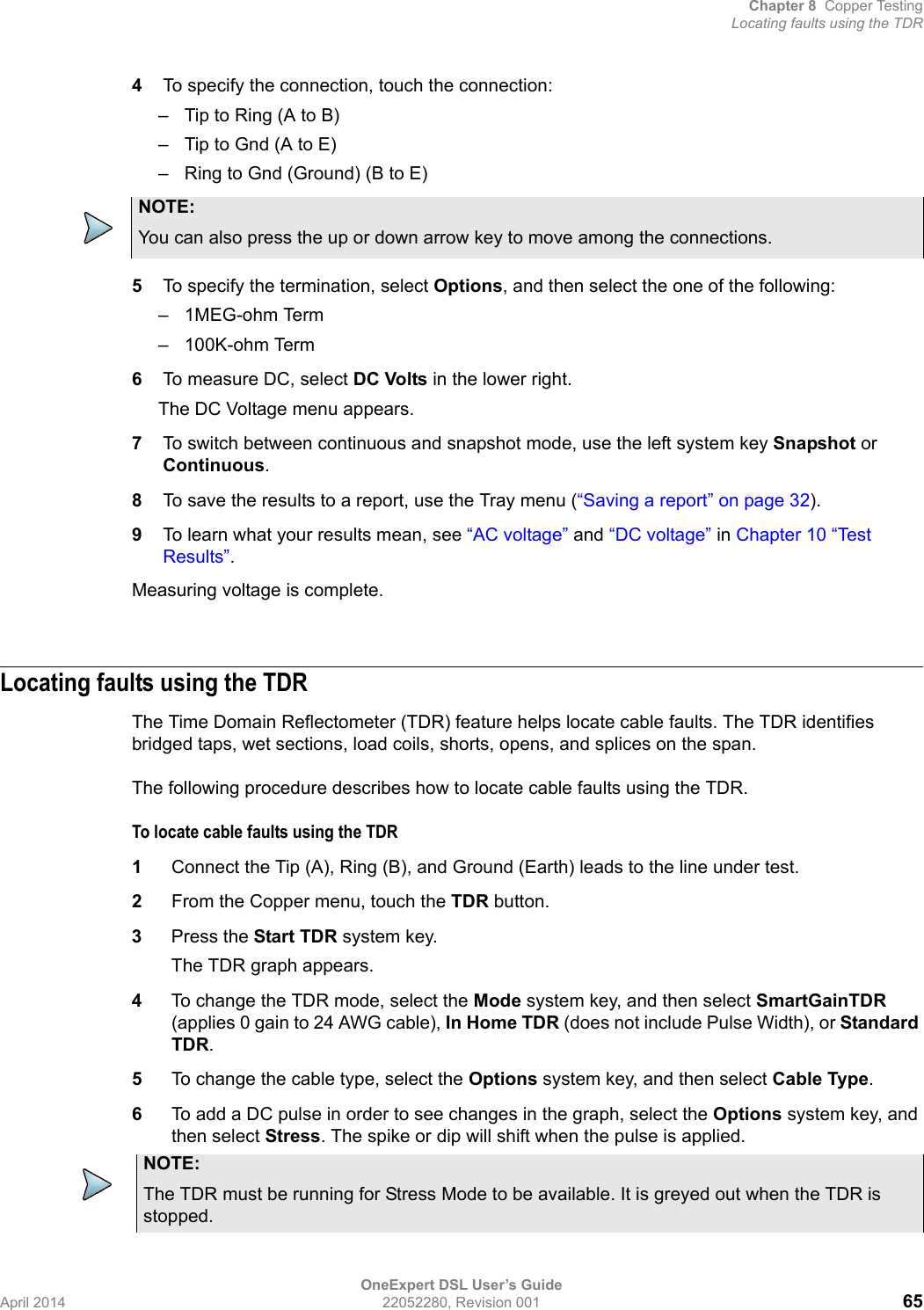


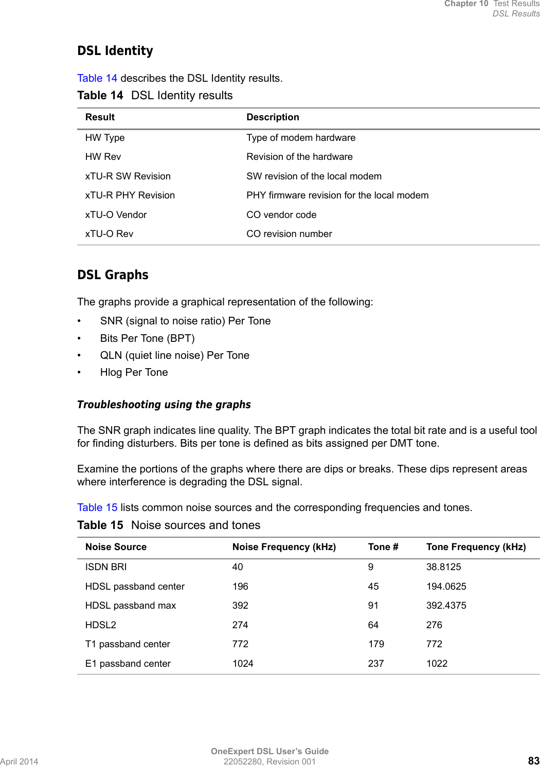
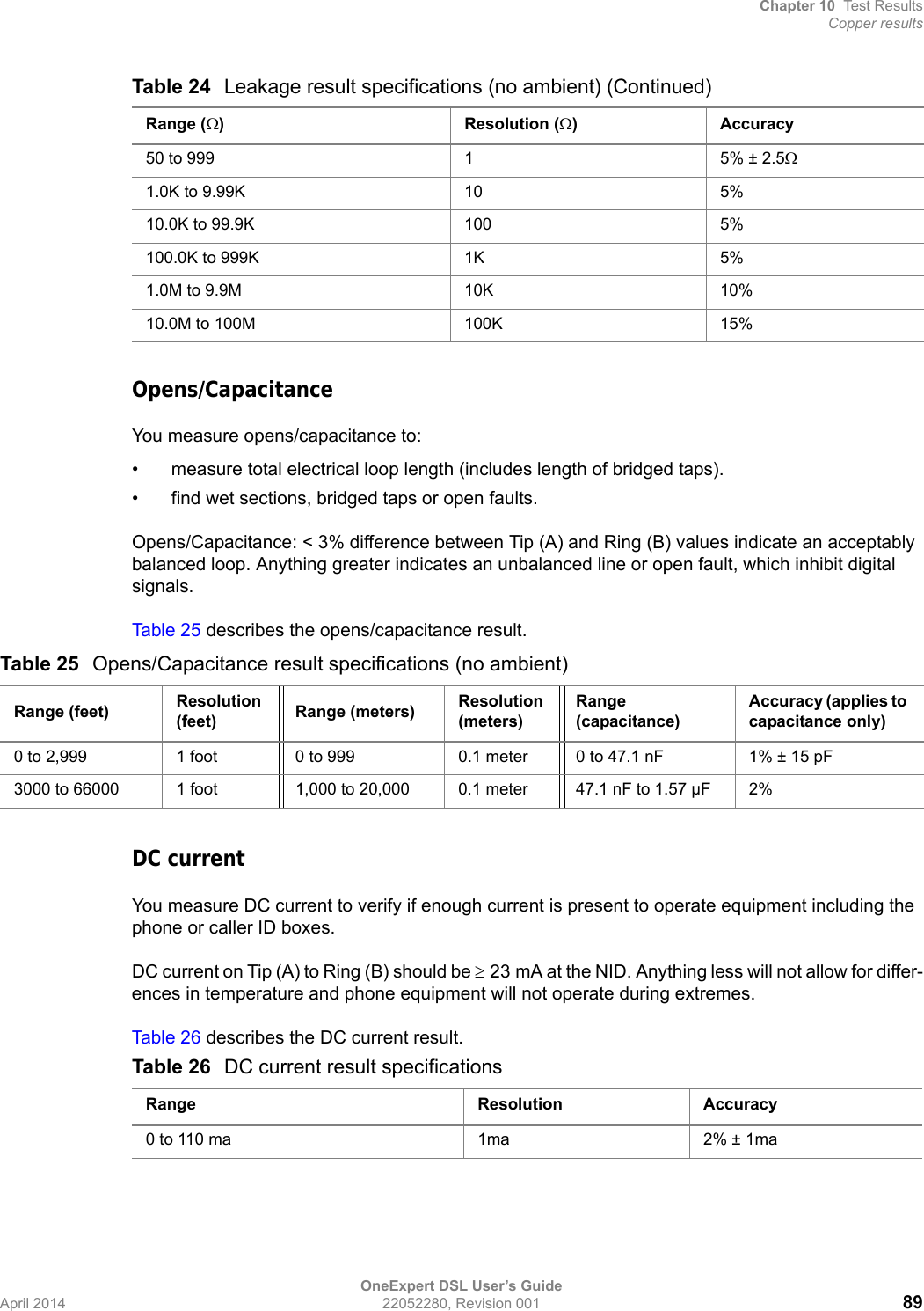
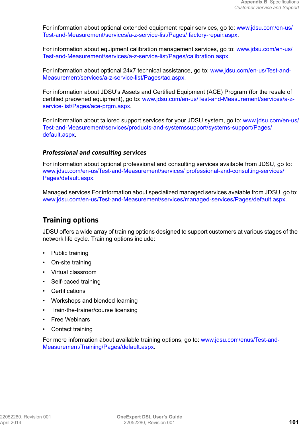
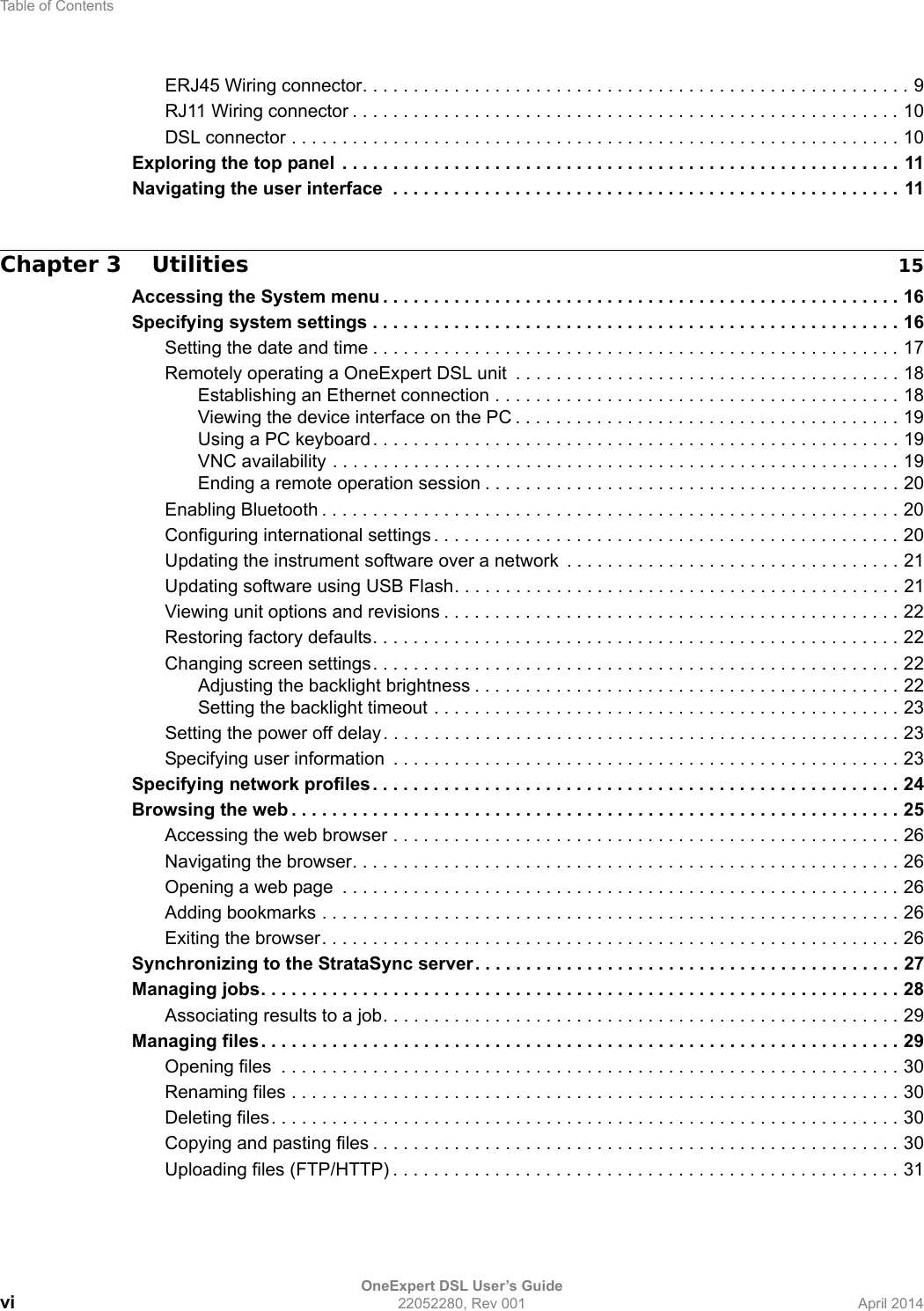
![Chapter 10 Test ResultsCopper resultsOneExpert DSL User’s GuideApril 2014 22052280, Revision 001 87Copper resultsThe copper results are described in the tables below.AC voltageYou measure AC volts to:• detect the presence of hazardous voltage.• measure stray or foreign voltages.• measure ringer voltage level.AC voltage results on Tip (A) to Ring (B) should be 0.0 volts. Tip (A) to ground and Ring (B) to ground should be equal to each other. Anything else indicates AC signal interference and/or an unbalanced line. Tab le 2 0 describes the AC voltage result.DC voltageYou measure DC volts to:• detect and measure CO/exchange battery voltage.• detect crossed battery conditions.To measure DC volts, remove the line battery and measure Tip (A) and Ring (B) to ground. It should be < 3.0 volts; anything else indicates crossed battery that inhibits digital signals.Tab le 2 1 describes the DC voltage result.Table 20 AC Voltage result specificationsRange (VAC) Resolution (V) AccuracyAC peak + [VDC] < 300 1 2% ± 1.0VWARNING: INSTRUMENT DAMAGEAlthough the OneExpert DSL OneExpert DSL is designed to measure hazardous voltage, it is designed to do so on telecom circuits, not power mains. Hazardous voltages may be on the power lines. 220 mains (RMS) are equivalent to 308 peak. Connecting to these circuits may result in damage to equipment or serious injury.Table 21 DC voltage result specificationsRange (VDC) Resolution (V) AccuracyAC peak + [VDC] < 300 1 2% ± 1.0V](https://usermanual.wiki/Laird-Connectivity/TIWI1-01.User-manual-1-of-2/User-Guide-2244588-Page-103.png)