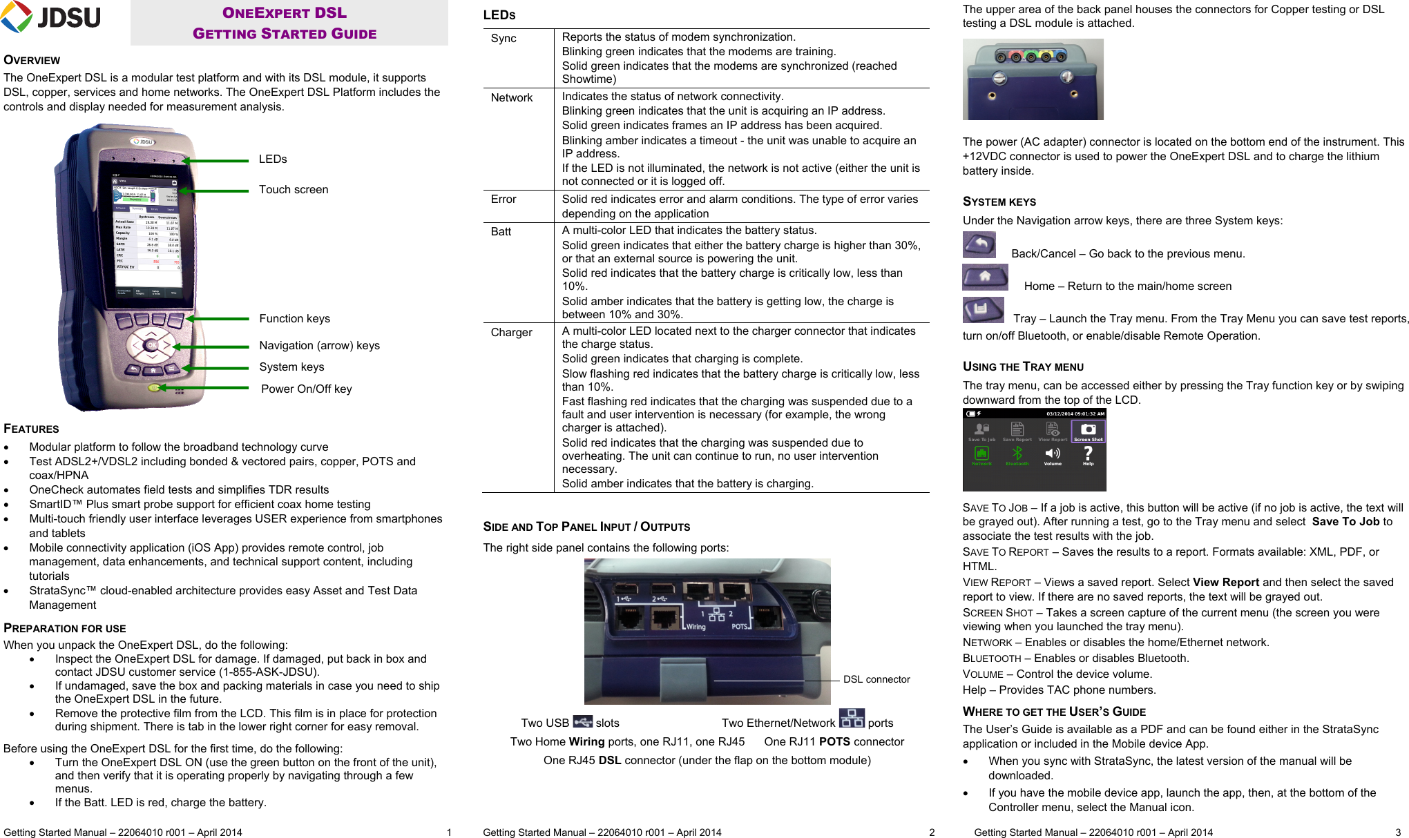
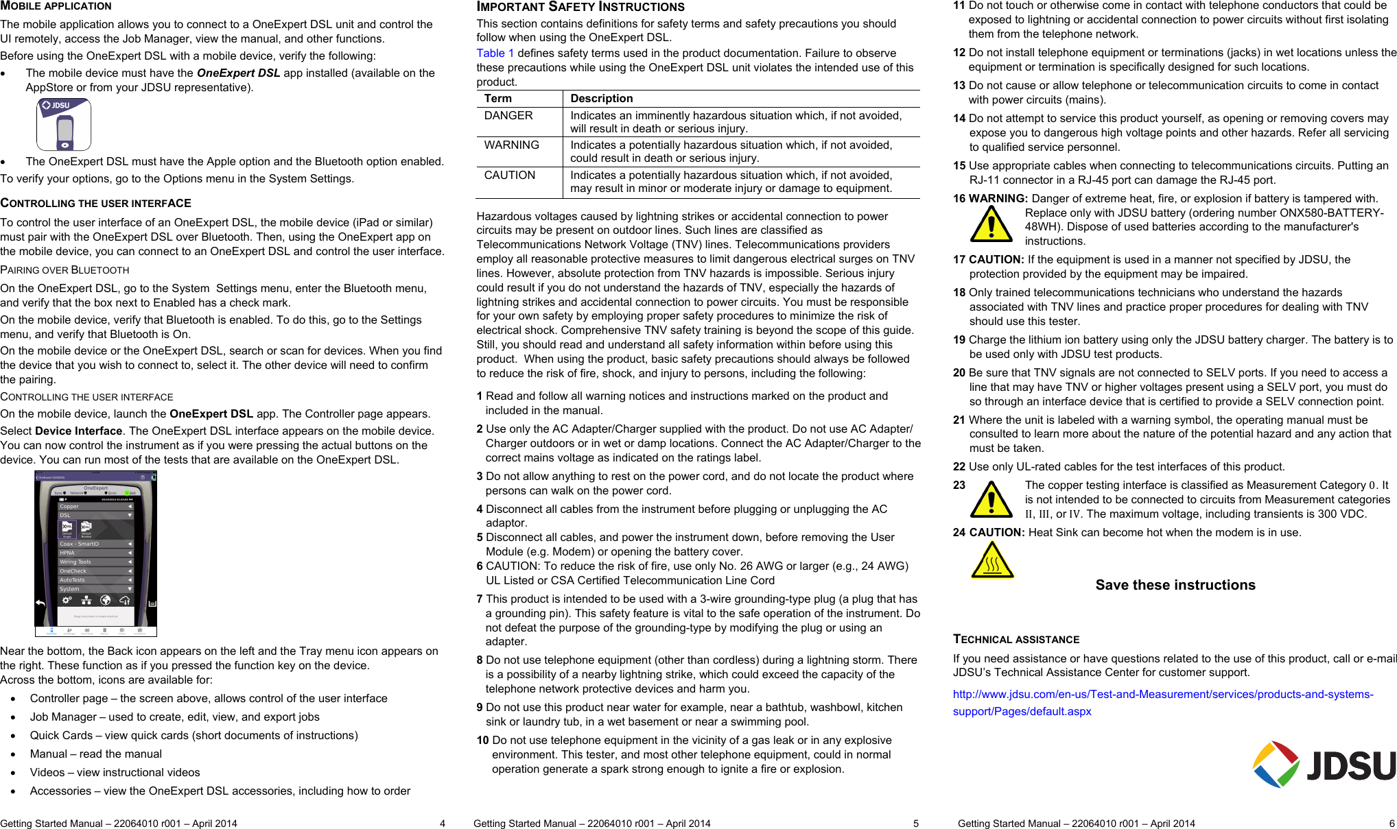
Laird Connectivity TIWI1-01 TIWI TRANSCEIVER MODULE User Manual OneExpert DSL Getting Started Guide

LS Research, LLC TIWI TRANSCEIVER MODULE OneExpert DSL Getting Started Guide

User manual 2 of 2

 Getting Started Manual – 22064010 r001 – April 2014   1           Getting Started Manual – 22064010 r001 – April 2014  2              Getting Started Manual – 22064010 r001 – April 2014      3  ONEEXPERT DSL  GETTING STARTED GUIDE OVERVIEW The OneExpert DSL is a modular test platform and with its DSL module, it supports DSL, copper, services and home networks. The OneExpert DSL Platform includes the controls and display needed for measurement analysis. FEATURES   Modular platform to follow the broadband technology curve   Test ADSL2+/VDSL2 including bonded & vectored pairs, copper, POTS and coax/HPNA    OneCheck automates field tests and simplifies TDR results   SmartID™ Plus smart probe support for efficient coax home testing    Multi-touch friendly user interface leverages USER experience from smartphones and tablets   Mobile connectivity application (iOS App) provides remote control, job management, data enhancements, and technical support content, including tutorials    StrataSync™ cloud-enabled architecture provides easy Asset and Test Data Management PREPARATION FOR USE When you unpack the OneExpert DSL, do the following:   Inspect the OneExpert DSL for damage. If damaged, put back in box and contact JDSU customer service (1-855-ASK-JDSU).   If undamaged, save the box and packing materials in case you need to ship the OneExpert DSL in the future.   Remove the protective film from the LCD. This film is in place for protection during shipment. There is tab in the lower right corner for easy removal. Before using the OneExpert DSL for the first time, do the following:   Turn the OneExpert DSL ON (use the green button on the front of the unit), and then verify that it is operating properly by navigating through a few menus.   If the Batt. LED is red, charge the battery.   LEDS Sync  Reports the status of modem synchronization. Blinking green indicates that the modems are training. Solid green indicates that the modems are synchronized (reached Showtime) Network  Indicates the status of network connectivity.  Blinking green indicates that the unit is acquiring an IP address. Solid green indicates frames an IP address has been acquired. Blinking amber indicates a timeout - the unit was unable to acquire an IP address. If the LED is not illuminated, the network is not active (either the unit is not connected or it is logged off. Error  Solid red indicates error and alarm conditions. The type of error varies depending on the application Batt  A multi-color LED that indicates the battery status. Solid green indicates that either the battery charge is higher than 30%, or that an external source is powering the unit. Solid red indicates that the battery charge is critically low, less than 10%. Solid amber indicates that the battery is getting low, the charge is between 10% and 30%. Charger  A multi-color LED located next to the charger connector that indicates the charge status. Solid green indicates that charging is complete. Slow flashing red indicates that the battery charge is critically low, less than 10%. Fast flashing red indicates that the charging was suspended due to a fault and user intervention is necessary (for example, the wrong charger is attached). Solid red indicates that the charging was suspended due to overheating. The unit can continue to run, no user intervention necessary. Solid amber indicates that the battery is charging.   SIDE AND TOP PANEL INPUT / OUTPUTS The right side panel contains the following ports:  Two USB   slots                                Two Ethernet/Network   ports Two Home Wiring ports, one RJ11, one RJ45      One RJ11 POTS connector One RJ45 DSL connector (under the flap on the bottom module)   The upper area of the back panel houses the connectors for Copper testing or DSL testing a DSL module is attached.  The power (AC adapter) connector is located on the bottom end of the instrument. This +12VDC connector is used to power the OneExpert DSL and to charge the lithium battery inside.  SYSTEM KEYS Under the Navigation arrow keys, there are three System keys:       Back/Cancel – Go back to the previous menu.      Home – Return to the main/home screen    Tray – Launch the Tray menu. From the Tray Menu you can save test reports, turn on/off Bluetooth, or enable/disable Remote Operation.   USING THE TRAY MENU The tray menu, can be accessed either by pressing the Tray function key or by swiping downward from the top of the LCD.  SAVE TO JOB – If a job is active, this button will be active (if no job is active, the text will be grayed out). After running a test, go to the Tray menu and select  Save To Job to associate the test results with the job. SAVE TO REPORT – Saves the results to a report. Formats available: XML, PDF, or HTML.  VIEW REPORT – Views a saved report. Select View Report and then select the saved report to view. If there are no saved reports, the text will be grayed out. SCREEN SHOT – Takes a screen capture of the current menu (the screen you were viewing when you launched the tray menu). NETWORK – Enables or disables the home/Ethernet network. BLUETOOTH – Enables or disables Bluetooth. VOLUME – Control the device volume. Help – Provides TAC phone numbers. WHERE TO GET THE USER’S GUIDE The User’s Guide is available as a PDF and can be found either in the StrataSync application or included in the Mobile device App.   When you sync with StrataSync, the latest version of the manual will be downloaded.   If you have the mobile device app, launch the app, then, at the bottom of the Controller menu, select the Manual icon.  DSL connectorLEDs Touch screen Function keys Navigation (arrow) keys System keys Power On/Off key
 Getting Started Manual – 22064010 r001 – April 2014   1           Getting Started Manual – 22064010 r001 – April 2014  2              Getting Started Manual – 22064010 r001 – April 2014      3  ONEEXPERT DSL  GETTING STARTED GUIDE OVERVIEW The OneExpert DSL is a modular test platform and with its DSL module, it supports DSL, copper, services and home networks. The OneExpert DSL Platform includes the controls and display needed for measurement analysis. FEATURES   Modular platform to follow the broadband technology curve   Test ADSL2+/VDSL2 including bonded & vectored pairs, copper, POTS and coax/HPNA    OneCheck automates field tests and simplifies TDR results   SmartID™ Plus smart probe support for efficient coax home testing    Multi-touch friendly user interface leverages USER experience from smartphones and tablets   Mobile connectivity application (iOS App) provides remote control, job management, data enhancements, and technical support content, including tutorials    StrataSync™ cloud-enabled architecture provides easy Asset and Test Data Management PREPARATION FOR USE When you unpack the OneExpert DSL, do the following:   Inspect the OneExpert DSL for damage. If damaged, put back in box and contact JDSU customer service (1-855-ASK-JDSU).   If undamaged, save the box and packing materials in case you need to ship the OneExpert DSL in the future.   Remove the protective film from the LCD. This film is in place for protection during shipment. There is tab in the lower right corner for easy removal. Before using the OneExpert DSL for the first time, do the following:   Turn the OneExpert DSL ON (use the green button on the front of the unit), and then verify that it is operating properly by navigating through a few menus.   If the Batt. LED is red, charge the battery.   LEDS Sync  Reports the status of modem synchronization. Blinking green indicates that the modems are training. Solid green indicates that the modems are synchronized (reached Showtime) Network  Indicates the status of network connectivity.  Blinking green indicates that the unit is acquiring an IP address. Solid green indicates frames an IP address has been acquired. Blinking amber indicates a timeout - the unit was unable to acquire an IP address. If the LED is not illuminated, the network is not active (either the unit is not connected or it is logged off. Error  Solid red indicates error and alarm conditions. The type of error varies depending on the application Batt  A multi-color LED that indicates the battery status. Solid green indicates that either the battery charge is higher than 30%, or that an external source is powering the unit. Solid red indicates that the battery charge is critically low, less than 10%. Solid amber indicates that the battery is getting low, the charge is between 10% and 30%. Charger  A multi-color LED located next to the charger connector that indicates the charge status. Solid green indicates that charging is complete. Slow flashing red indicates that the battery charge is critically low, less than 10%. Fast flashing red indicates that the charging was suspended due to a fault and user intervention is necessary (for example, the wrong charger is attached). Solid red indicates that the charging was suspended due to overheating. The unit can continue to run, no user intervention necessary. Solid amber indicates that the battery is charging.   SIDE AND TOP PANEL INPUT / OUTPUTS The right side panel contains the following ports:  Two USB   slots                                Two Ethernet/Network   ports Two Home Wiring ports, one RJ11, one RJ45      One RJ11 POTS connector One RJ45 DSL connector (under the flap on the bottom module)   The upper area of the back panel houses the connectors for Copper testing or DSL testing a DSL module is attached.  The power (AC adapter) connector is located on the bottom end of the instrument. This +12VDC connector is used to power the OneExpert DSL and to charge the lithium battery inside.  SYSTEM KEYS Under the Navigation arrow keys, there are three System keys:       Back/Cancel – Go back to the previous menu.      Home – Return to the main/home screen    Tray – Launch the Tray menu. From the Tray Menu you can save test reports, turn on/off Bluetooth, or enable/disable Remote Operation.   USING THE TRAY MENU The tray menu, can be accessed either by pressing the Tray function key or by swiping downward from the top of the LCD.  SAVE TO JOB – If a job is active, this button will be active (if no job is active, the text will be grayed out). After running a test, go to the Tray menu and select  Save To Job to associate the test results with the job. SAVE TO REPORT – Saves the results to a report. Formats available: XML, PDF, or HTML.  VIEW REPORT – Views a saved report. Select View Report and then select the saved report to view. If there are no saved reports, the text will be grayed out. SCREEN SHOT – Takes a screen capture of the current menu (the screen you were viewing when you launched the tray menu). NETWORK – Enables or disables the home/Ethernet network. BLUETOOTH – Enables or disables Bluetooth. VOLUME – Control the device volume. Help – Provides TAC phone numbers. WHERE TO GET THE USER’S GUIDE The User’s Guide is available as a PDF and can be found either in the StrataSync application or included in the Mobile device App.   When you sync with StrataSync, the latest version of the manual will be downloaded.   If you have the mobile device app, launch the app, then, at the bottom of the Controller menu, select the Manual icon.  DSL connectorLEDs Touch screen Function keys Navigation (arrow) keys System keys Power On/Off key
 Getting Started Manual – 22064010 r001 – April 2014   1           Getting Started Manual – 22064010 r001 – April 2014  2              Getting Started Manual – 22064010 r001 – April 2014      3  ONEEXPERT DSL  GETTING STARTED GUIDE OVERVIEW The OneExpert DSL is a modular test platform and with its DSL module, it supports DSL, copper, services and home networks. The OneExpert DSL Platform includes the controls and display needed for measurement analysis. FEATURES   Modular platform to follow the broadband technology curve   Test ADSL2+/VDSL2 including bonded & vectored pairs, copper, POTS and coax/HPNA    OneCheck automates field tests and simplifies TDR results   SmartID™ Plus smart probe support for efficient coax home testing    Multi-touch friendly user interface leverages USER experience from smartphones and tablets   Mobile connectivity application (iOS App) provides remote control, job management, data enhancements, and technical support content, including tutorials    StrataSync™ cloud-enabled architecture provides easy Asset and Test Data Management PREPARATION FOR USE When you unpack the OneExpert DSL, do the following:   Inspect the OneExpert DSL for damage. If damaged, put back in box and contact JDSU customer service (1-855-ASK-JDSU).   If undamaged, save the box and packing materials in case you need to ship the OneExpert DSL in the future.   Remove the protective film from the LCD. This film is in place for protection during shipment. There is tab in the lower right corner for easy removal. Before using the OneExpert DSL for the first time, do the following:   Turn the OneExpert DSL ON (use the green button on the front of the unit), and then verify that it is operating properly by navigating through a few menus.   If the Batt. LED is red, charge the battery.   LEDS Sync  Reports the status of modem synchronization. Blinking green indicates that the modems are training. Solid green indicates that the modems are synchronized (reached Showtime) Network  Indicates the status of network connectivity.  Blinking green indicates that the unit is acquiring an IP address. Solid green indicates frames an IP address has been acquired. Blinking amber indicates a timeout - the unit was unable to acquire an IP address. If the LED is not illuminated, the network is not active (either the unit is not connected or it is logged off. Error  Solid red indicates error and alarm conditions. The type of error varies depending on the application Batt  A multi-color LED that indicates the battery status. Solid green indicates that either the battery charge is higher than 30%, or that an external source is powering the unit. Solid red indicates that the battery charge is critically low, less than 10%. Solid amber indicates that the battery is getting low, the charge is between 10% and 30%. Charger  A multi-color LED located next to the charger connector that indicates the charge status. Solid green indicates that charging is complete. Slow flashing red indicates that the battery charge is critically low, less than 10%. Fast flashing red indicates that the charging was suspended due to a fault and user intervention is necessary (for example, the wrong charger is attached). Solid red indicates that the charging was suspended due to overheating. The unit can continue to run, no user intervention necessary. Solid amber indicates that the battery is charging.   SIDE AND TOP PANEL INPUT / OUTPUTS The right side panel contains the following ports:  Two USB   slots                                Two Ethernet/Network   ports Two Home Wiring ports, one RJ11, one RJ45      One RJ11 POTS connector One RJ45 DSL connector (under the flap on the bottom module)   The upper area of the back panel houses the connectors for Copper testing or DSL testing a DSL module is attached.  The power (AC adapter) connector is located on the bottom end of the instrument. This +12VDC connector is used to power the OneExpert DSL and to charge the lithium battery inside.  SYSTEM KEYS Under the Navigation arrow keys, there are three System keys:       Back/Cancel – Go back to the previous menu.      Home – Return to the main/home screen    Tray – Launch the Tray menu. From the Tray Menu you can save test reports, turn on/off Bluetooth, or enable/disable Remote Operation.   USING THE TRAY MENU The tray menu, can be accessed either by pressing the Tray function key or by swiping downward from the top of the LCD.  SAVE TO JOB – If a job is active, this button will be active (if no job is active, the text will be grayed out). After running a test, go to the Tray menu and select  Save To Job to associate the test results with the job. SAVE TO REPORT – Saves the results to a report. Formats available: XML, PDF, or HTML.  VIEW REPORT – Views a saved report. Select View Report and then select the saved report to view. If there are no saved reports, the text will be grayed out. SCREEN SHOT – Takes a screen capture of the current menu (the screen you were viewing when you launched the tray menu). NETWORK – Enables or disables the home/Ethernet network. BLUETOOTH – Enables or disables Bluetooth. VOLUME – Control the device volume. Help – Provides TAC phone numbers. WHERE TO GET THE USER’S GUIDE The User’s Guide is available as a PDF and can be found either in the StrataSync application or included in the Mobile device App.   When you sync with StrataSync, the latest version of the manual will be downloaded.   If you have the mobile device app, launch the app, then, at the bottom of the Controller menu, select the Manual icon.  DSL connectorLEDs Touch screen Function keys Navigation (arrow) keys System keys Power On/Off key
 Getting Started Manual – 22064010 r001 – April 2014   4          Getting Started Manual – 22064010 r001 – April 2014  5              Getting Started Manual – 22064010 r001 – April 2014  6  MOBILE APPLICATION The mobile application allows you to connect to a OneExpert DSL unit and control the UI remotely, access the Job Manager, view the manual, and other functions.  Before using the OneExpert DSL with a mobile device, verify the following:   The mobile device must have the OneExpert DSL app installed (available on the AppStore or from your JDSU representative).                  The OneExpert DSL must have the Apple option and the Bluetooth option enabled. To verify your options, go to the Options menu in the System Settings. CONTROLLING THE USER INTERFACE To control the user interface of an OneExpert DSL, the mobile device (iPad or similar) must pair with the OneExpert DSL over Bluetooth. Then, using the OneExpert app on the mobile device, you can connect to an OneExpert DSL and control the user interface. PAIRING OVER BLUETOOTH On the OneExpert DSL, go to the System  Settings menu, enter the Bluetooth menu, and verify that the box next to Enabled has a check mark. On the mobile device, verify that Bluetooth is enabled. To do this, go to the Settings menu, and verify that Bluetooth is On. On the mobile device or the OneExpert DSL, search or scan for devices. When you find the device that you wish to connect to, select it. The other device will need to confirm the pairing. CONTROLLING THE USER INTERFACE On the mobile device, launch the OneExpert DSL app. The Controller page appears.  Select Device Interface. The OneExpert DSL interface appears on the mobile device. You can now control the instrument as if you were pressing the actual buttons on the device. You can run most of the tests that are available on the OneExpert DSL.              Near the bottom, the Back icon appears on the left and the Tray menu icon appears on the right. These function as if you pressed the function key on the device.  Across the bottom, icons are available for:   Controller page – the screen above, allows control of the user interface   Job Manager – used to create, edit, view, and export jobs   Quick Cards – view quick cards (short documents of instructions)   Manual – read the manual   Videos – view instructional videos   Accessories – view the OneExpert DSL accessories, including how to order IMPORTANT SAFETY INSTRUCTIONS This section contains definitions for safety terms and safety precautions you should follow when using the OneExpert DSL. Table 1 defines safety terms used in the product documentation. Failure to observe these precautions while using the OneExpert DSL unit violates the intended use of this product. Term   Description DANGER   Indicates an imminently hazardous situation which, if not avoided, will result in death or serious injury. WARNING   Indicates a potentially hazardous situation which, if not avoided, could result in death or serious injury. CAUTION   Indicates a potentially hazardous situation which, if not avoided, may result in minor or moderate injury or damage to equipment.  Hazardous voltages caused by lightning strikes or accidental connection to power circuits may be present on outdoor lines. Such lines are classified as Telecommunications Network Voltage (TNV) lines. Telecommunications providers employ all reasonable protective measures to limit dangerous electrical surges on TNV lines. However, absolute protection from TNV hazards is impossible. Serious injury could result if you do not understand the hazards of TNV, especially the hazards of lightning strikes and accidental connection to power circuits. You must be responsible for your own safety by employing proper safety procedures to minimize the risk of electrical shock. Comprehensive TNV safety training is beyond the scope of this guide. Still, you should read and understand all safety information within before using this product.  When using the product, basic safety precautions should always be followed to reduce the risk of fire, shock, and injury to persons, including the following: 1 Read and follow all warning notices and instructions marked on the product and included in the manual. 2 Use only the AC Adapter/Charger supplied with the product. Do not use AC Adapter/ Charger outdoors or in wet or damp locations. Connect the AC Adapter/Charger to the correct mains voltage as indicated on the ratings label. 3 Do not allow anything to rest on the power cord, and do not locate the product where persons can walk on the power cord. 4 Disconnect all cables from the instrument before plugging or unplugging the AC    adaptor. 5 Disconnect all cables, and power the instrument down, before removing the User     Module (e.g. Modem) or opening the battery cover. 6 CAUTION: To reduce the risk of fire, use only No. 26 AWG or larger (e.g., 24 AWG)    UL Listed or CSA Certified Telecommunication Line Cord 7 This product is intended to be used with a 3-wire grounding-type plug (a plug that has a grounding pin). This safety feature is vital to the safe operation of the instrument. Do not defeat the purpose of the grounding-type by modifying the plug or using an adapter. 8 Do not use telephone equipment (other than cordless) during a lightning storm. There is a possibility of a nearby lightning strike, which could exceed the capacity of the telephone network protective devices and harm you. 9 Do not use this product near water for example, near a bathtub, washbowl, kitchen    sink or laundry tub, in a wet basement or near a swimming pool. 10 Do not use telephone equipment in the vicinity of a gas leak or in any explosive   environment. This tester, and most other telephone equipment, could in normal   operation generate a spark strong enough to ignite a fire or explosion. 11 Do not touch or otherwise come in contact with telephone conductors that could be   exposed to lightning or accidental connection to power circuits without first isolating   them from the telephone network. 12 Do not install telephone equipment or terminations (jacks) in wet locations unless the   equipment or termination is specifically designed for such locations. 13 Do not cause or allow telephone or telecommunication circuits to come in contact    with power circuits (mains). 14 Do not attempt to service this product yourself, as opening or removing covers may expose you to dangerous high voltage points and other hazards. Refer all servicing to qualified service personnel. 15 Use appropriate cables when connecting to telecommunications circuits. Putting an RJ-11 connector in a RJ-45 port can damage the RJ-45 port. 16 WARNING: Danger of extreme heat, fire, or explosion if battery is tampered with. Replace only with JDSU battery (ordering number ONX580-BATTERY-48WH). Dispose of used batteries according to the manufacturer's instructions. 17 CAUTION: If the equipment is used in a manner not specified by JDSU, the protection provided by the equipment may be impaired. 18 Only trained telecommunications technicians who understand the hazards associated with TNV lines and practice proper procedures for dealing with TNV should use this tester. 19 Charge the lithium ion battery using only the JDSU battery charger. The battery is to be used only with JDSU test products. 20 Be sure that TNV signals are not connected to SELV ports. If you need to access a line that may have TNV or higher voltages present using a SELV port, you must do so through an interface device that is certified to provide a SELV connection point. 21 Where the unit is labeled with a warning symbol, the operating manual must be consulted to learn more about the nature of the potential hazard and any action that must be taken. 22 Use only UL-rated cables for the test interfaces of this product. 23   The copper testing interface is classified as Measurement Category 0. It is not intended to be connected to circuits from Measurement categories II, III, or IV. The maximum voltage, including transients is 300 VDC. 24  CAUTION: Heat Sink can become hot when the modem is in use.   Save these instructions   TECHNICAL ASSISTANCE  If you need assistance or have questions related to the use of this product, call or e-mail JDSU’s Technical Assistance Center for customer support. http://www.jdsu.com/en-us/Test-and-Measurement/services/products-and-systems-support/Pages/default.aspx
 Getting Started Manual – 22064010 r001 – April 2014   4          Getting Started Manual – 22064010 r001 – April 2014  5              Getting Started Manual – 22064010 r001 – April 2014  6  MOBILE APPLICATION The mobile application allows you to connect to a OneExpert DSL unit and control the UI remotely, access the Job Manager, view the manual, and other functions.  Before using the OneExpert DSL with a mobile device, verify the following:   The mobile device must have the OneExpert DSL app installed (available on the AppStore or from your JDSU representative).                  The OneExpert DSL must have the Apple option and the Bluetooth option enabled. To verify your options, go to the Options menu in the System Settings. CONTROLLING THE USER INTERFACE To control the user interface of an OneExpert DSL, the mobile device (iPad or similar) must pair with the OneExpert DSL over Bluetooth. Then, using the OneExpert app on the mobile device, you can connect to an OneExpert DSL and control the user interface. PAIRING OVER BLUETOOTH On the OneExpert DSL, go to the System  Settings menu, enter the Bluetooth menu, and verify that the box next to Enabled has a check mark. On the mobile device, verify that Bluetooth is enabled. To do this, go to the Settings menu, and verify that Bluetooth is On. On the mobile device or the OneExpert DSL, search or scan for devices. When you find the device that you wish to connect to, select it. The other device will need to confirm the pairing. CONTROLLING THE USER INTERFACE On the mobile device, launch the OneExpert DSL app. The Controller page appears.  Select Device Interface. The OneExpert DSL interface appears on the mobile device. You can now control the instrument as if you were pressing the actual buttons on the device. You can run most of the tests that are available on the OneExpert DSL.              Near the bottom, the Back icon appears on the left and the Tray menu icon appears on the right. These function as if you pressed the function key on the device.  Across the bottom, icons are available for:   Controller page – the screen above, allows control of the user interface   Job Manager – used to create, edit, view, and export jobs   Quick Cards – view quick cards (short documents of instructions)   Manual – read the manual   Videos – view instructional videos   Accessories – view the OneExpert DSL accessories, including how to order IMPORTANT SAFETY INSTRUCTIONS This section contains definitions for safety terms and safety precautions you should follow when using the OneExpert DSL. Table 1 defines safety terms used in the product documentation. Failure to observe these precautions while using the OneExpert DSL unit violates the intended use of this product. Term   Description DANGER   Indicates an imminently hazardous situation which, if not avoided, will result in death or serious injury. WARNING   Indicates a potentially hazardous situation which, if not avoided, could result in death or serious injury. CAUTION   Indicates a potentially hazardous situation which, if not avoided, may result in minor or moderate injury or damage to equipment.  Hazardous voltages caused by lightning strikes or accidental connection to power circuits may be present on outdoor lines. Such lines are classified as Telecommunications Network Voltage (TNV) lines. Telecommunications providers employ all reasonable protective measures to limit dangerous electrical surges on TNV lines. However, absolute protection from TNV hazards is impossible. Serious injury could result if you do not understand the hazards of TNV, especially the hazards of lightning strikes and accidental connection to power circuits. You must be responsible for your own safety by employing proper safety procedures to minimize the risk of electrical shock. Comprehensive TNV safety training is beyond the scope of this guide. Still, you should read and understand all safety information within before using this product.  When using the product, basic safety precautions should always be followed to reduce the risk of fire, shock, and injury to persons, including the following: 1 Read and follow all warning notices and instructions marked on the product and included in the manual. 2 Use only the AC Adapter/Charger supplied with the product. Do not use AC Adapter/ Charger outdoors or in wet or damp locations. Connect the AC Adapter/Charger to the correct mains voltage as indicated on the ratings label. 3 Do not allow anything to rest on the power cord, and do not locate the product where persons can walk on the power cord. 4 Disconnect all cables from the instrument before plugging or unplugging the AC    adaptor. 5 Disconnect all cables, and power the instrument down, before removing the User     Module (e.g. Modem) or opening the battery cover. 6 CAUTION: To reduce the risk of fire, use only No. 26 AWG or larger (e.g., 24 AWG)    UL Listed or CSA Certified Telecommunication Line Cord 7 This product is intended to be used with a 3-wire grounding-type plug (a plug that has a grounding pin). This safety feature is vital to the safe operation of the instrument. Do not defeat the purpose of the grounding-type by modifying the plug or using an adapter. 8 Do not use telephone equipment (other than cordless) during a lightning storm. There is a possibility of a nearby lightning strike, which could exceed the capacity of the telephone network protective devices and harm you. 9 Do not use this product near water for example, near a bathtub, washbowl, kitchen    sink or laundry tub, in a wet basement or near a swimming pool. 10 Do not use telephone equipment in the vicinity of a gas leak or in any explosive   environment. This tester, and most other telephone equipment, could in normal   operation generate a spark strong enough to ignite a fire or explosion. 11 Do not touch or otherwise come in contact with telephone conductors that could be   exposed to lightning or accidental connection to power circuits without first isolating   them from the telephone network. 12 Do not install telephone equipment or terminations (jacks) in wet locations unless the   equipment or termination is specifically designed for such locations. 13 Do not cause or allow telephone or telecommunication circuits to come in contact    with power circuits (mains). 14 Do not attempt to service this product yourself, as opening or removing covers may expose you to dangerous high voltage points and other hazards. Refer all servicing to qualified service personnel. 15 Use appropriate cables when connecting to telecommunications circuits. Putting an RJ-11 connector in a RJ-45 port can damage the RJ-45 port. 16 WARNING: Danger of extreme heat, fire, or explosion if battery is tampered with. Replace only with JDSU battery (ordering number ONX580-BATTERY-48WH). Dispose of used batteries according to the manufacturer's instructions. 17 CAUTION: If the equipment is used in a manner not specified by JDSU, the protection provided by the equipment may be impaired. 18 Only trained telecommunications technicians who understand the hazards associated with TNV lines and practice proper procedures for dealing with TNV should use this tester. 19 Charge the lithium ion battery using only the JDSU battery charger. The battery is to be used only with JDSU test products. 20 Be sure that TNV signals are not connected to SELV ports. If you need to access a line that may have TNV or higher voltages present using a SELV port, you must do so through an interface device that is certified to provide a SELV connection point. 21 Where the unit is labeled with a warning symbol, the operating manual must be consulted to learn more about the nature of the potential hazard and any action that must be taken. 22 Use only UL-rated cables for the test interfaces of this product. 23   The copper testing interface is classified as Measurement Category 0. It is not intended to be connected to circuits from Measurement categories II, III, or IV. The maximum voltage, including transients is 300 VDC. 24  CAUTION: Heat Sink can become hot when the modem is in use.   Save these instructions   TECHNICAL ASSISTANCE  If you need assistance or have questions related to the use of this product, call or e-mail JDSU’s Technical Assistance Center for customer support. http://www.jdsu.com/en-us/Test-and-Measurement/services/products-and-systems-support/Pages/default.aspx
 Getting Started Manual – 22064010 r001 – April 2014   4          Getting Started Manual – 22064010 r001 – April 2014  5              Getting Started Manual – 22064010 r001 – April 2014  6  MOBILE APPLICATION The mobile application allows you to connect to a OneExpert DSL unit and control the UI remotely, access the Job Manager, view the manual, and other functions.  Before using the OneExpert DSL with a mobile device, verify the following:   The mobile device must have the OneExpert DSL app installed (available on the AppStore or from your JDSU representative).                  The OneExpert DSL must have the Apple option and the Bluetooth option enabled. To verify your options, go to the Options menu in the System Settings. CONTROLLING THE USER INTERFACE To control the user interface of an OneExpert DSL, the mobile device (iPad or similar) must pair with the OneExpert DSL over Bluetooth. Then, using the OneExpert app on the mobile device, you can connect to an OneExpert DSL and control the user interface. PAIRING OVER BLUETOOTH On the OneExpert DSL, go to the System  Settings menu, enter the Bluetooth menu, and verify that the box next to Enabled has a check mark. On the mobile device, verify that Bluetooth is enabled. To do this, go to the Settings menu, and verify that Bluetooth is On. On the mobile device or the OneExpert DSL, search or scan for devices. When you find the device that you wish to connect to, select it. The other device will need to confirm the pairing. CONTROLLING THE USER INTERFACE On the mobile device, launch the OneExpert DSL app. The Controller page appears.  Select Device Interface. The OneExpert DSL interface appears on the mobile device. You can now control the instrument as if you were pressing the actual buttons on the device. You can run most of the tests that are available on the OneExpert DSL.              Near the bottom, the Back icon appears on the left and the Tray menu icon appears on the right. These function as if you pressed the function key on the device.  Across the bottom, icons are available for:   Controller page – the screen above, allows control of the user interface   Job Manager – used to create, edit, view, and export jobs   Quick Cards – view quick cards (short documents of instructions)   Manual – read the manual   Videos – view instructional videos   Accessories – view the OneExpert DSL accessories, including how to order IMPORTANT SAFETY INSTRUCTIONS This section contains definitions for safety terms and safety precautions you should follow when using the OneExpert DSL. Table 1 defines safety terms used in the product documentation. Failure to observe these precautions while using the OneExpert DSL unit violates the intended use of this product. Term   Description DANGER   Indicates an imminently hazardous situation which, if not avoided, will result in death or serious injury. WARNING   Indicates a potentially hazardous situation which, if not avoided, could result in death or serious injury. CAUTION   Indicates a potentially hazardous situation which, if not avoided, may result in minor or moderate injury or damage to equipment.  Hazardous voltages caused by lightning strikes or accidental connection to power circuits may be present on outdoor lines. Such lines are classified as Telecommunications Network Voltage (TNV) lines. Telecommunications providers employ all reasonable protective measures to limit dangerous electrical surges on TNV lines. However, absolute protection from TNV hazards is impossible. Serious injury could result if you do not understand the hazards of TNV, especially the hazards of lightning strikes and accidental connection to power circuits. You must be responsible for your own safety by employing proper safety procedures to minimize the risk of electrical shock. Comprehensive TNV safety training is beyond the scope of this guide. Still, you should read and understand all safety information within before using this product.  When using the product, basic safety precautions should always be followed to reduce the risk of fire, shock, and injury to persons, including the following: 1 Read and follow all warning notices and instructions marked on the product and included in the manual. 2 Use only the AC Adapter/Charger supplied with the product. Do not use AC Adapter/ Charger outdoors or in wet or damp locations. Connect the AC Adapter/Charger to the correct mains voltage as indicated on the ratings label. 3 Do not allow anything to rest on the power cord, and do not locate the product where persons can walk on the power cord. 4 Disconnect all cables from the instrument before plugging or unplugging the AC    adaptor. 5 Disconnect all cables, and power the instrument down, before removing the User     Module (e.g. Modem) or opening the battery cover. 6 CAUTION: To reduce the risk of fire, use only No. 26 AWG or larger (e.g., 24 AWG)    UL Listed or CSA Certified Telecommunication Line Cord 7 This product is intended to be used with a 3-wire grounding-type plug (a plug that has a grounding pin). This safety feature is vital to the safe operation of the instrument. Do not defeat the purpose of the grounding-type by modifying the plug or using an adapter. 8 Do not use telephone equipment (other than cordless) during a lightning storm. There is a possibility of a nearby lightning strike, which could exceed the capacity of the telephone network protective devices and harm you. 9 Do not use this product near water for example, near a bathtub, washbowl, kitchen    sink or laundry tub, in a wet basement or near a swimming pool. 10 Do not use telephone equipment in the vicinity of a gas leak or in any explosive   environment. This tester, and most other telephone equipment, could in normal   operation generate a spark strong enough to ignite a fire or explosion. 11 Do not touch or otherwise come in contact with telephone conductors that could be   exposed to lightning or accidental connection to power circuits without first isolating   them from the telephone network. 12 Do not install telephone equipment or terminations (jacks) in wet locations unless the   equipment or termination is specifically designed for such locations. 13 Do not cause or allow telephone or telecommunication circuits to come in contact    with power circuits (mains). 14 Do not attempt to service this product yourself, as opening or removing covers may expose you to dangerous high voltage points and other hazards. Refer all servicing to qualified service personnel. 15 Use appropriate cables when connecting to telecommunications circuits. Putting an RJ-11 connector in a RJ-45 port can damage the RJ-45 port. 16 WARNING: Danger of extreme heat, fire, or explosion if battery is tampered with. Replace only with JDSU battery (ordering number ONX580-BATTERY-48WH). Dispose of used batteries according to the manufacturer's instructions. 17 CAUTION: If the equipment is used in a manner not specified by JDSU, the protection provided by the equipment may be impaired. 18 Only trained telecommunications technicians who understand the hazards associated with TNV lines and practice proper procedures for dealing with TNV should use this tester. 19 Charge the lithium ion battery using only the JDSU battery charger. The battery is to be used only with JDSU test products. 20 Be sure that TNV signals are not connected to SELV ports. If you need to access a line that may have TNV or higher voltages present using a SELV port, you must do so through an interface device that is certified to provide a SELV connection point. 21 Where the unit is labeled with a warning symbol, the operating manual must be consulted to learn more about the nature of the potential hazard and any action that must be taken. 22 Use only UL-rated cables for the test interfaces of this product. 23   The copper testing interface is classified as Measurement Category 0. It is not intended to be connected to circuits from Measurement categories II, III, or IV. The maximum voltage, including transients is 300 VDC. 24  CAUTION: Heat Sink can become hot when the modem is in use.   Save these instructions   TECHNICAL ASSISTANCE  If you need assistance or have questions related to the use of this product, call or e-mail JDSU’s Technical Assistance Center for customer support. http://www.jdsu.com/en-us/Test-and-Measurement/services/products-and-systems-support/Pages/default.aspx

Navigation menu