Laird Connectivity TIWI1-01 TIWI TRANSCEIVER MODULE User Manual OneExpert DSL User s Guide
LS Research, LLC TIWI TRANSCEIVER MODULE OneExpert DSL User s Guide
Contents
- 1. Manual
- 2. BLE model manual
- 3. R2 model manual
- 4. User manual 1 of 2
- 5. User manual 2 of 2
User manual 1 of 2

OneExpert DSL
User’s Guide

OneExpert DSL User’s Guide
ii 22052280, Rev 001 April 2014
Notice
Every effort was made to ensure that the information in this document was accurate at the time of
printing. However, information is subject to change without notice, and JDSU reserves the right to
provide an addendum to this document with information not available at the time that this document
was created.
Copyright
© Copyright 2014 JDS Uniphase Corporation. All rights reserved. JDSU, Network and Service
Enablement, and the JDSU logo are trademarks of JDS Uniphase Corporation (“JDS Uniphase”).
All other trademarks and registered trademarks are the property of their respective owners. No part
of this manual may be reproduced or transmitted electronically or otherwise without written permis-
sion of the publisher.
Copyright release
Reproduction and distribution of this guide is authorized for Government purposes only.
Trademarks
JDS Uniphase, JDSU, and OneExpert DSL are trademarks or registered trademarks of
JDS Uniphase Corporation in the United States and/or other countries.
Bluetooth is a registered trademark of The Bluetooth SIG, Inc. in the United States and/or other
countries.
CopperGate is either a trademark or registered trademark of CopperGate Communications, Ltd in
the United States and/or other countries.
iPad, iPod, and iPhone are registered trademarks of Apple, Inc. in the United States and/or other
countries.
MotoPLYR is either a trademark or registered trademark of Motorola Mobility, Inc. in the United
States and/or other countries.
StrataSync is a registered trademark of JDS Uniphase Corporation in the United States and/or other
countries.
Specifications, terms, and conditions are subject to change without notice. All trademarks and reg-
istered trademarks are the property of their respective companies.
Ordering information
This guide is a product of JDSU's Technical Information Development Department, issued as part
of the OneExpert DSL. You can obtain the manual through StrataSync. A printed quick card ships
with the instrument and can be downloaded through StrataSync.
OneExpert DSL User’s Guide
April 2014 22052280, Rev 001 iii
Terms and conditions
Specifications, terms, and conditions are subject to change without notice. The provision of hard-
ware, services, and/or software are subject to JDSU’s standard terms and conditions, available at
www.jdsu.com/terms.
Federal Communications Commission (FCC) Notice
This equipment has been tested and found to comply with the limits for a Class A digital device,
pursuant to part 15 of the FCC Rules. These limits are designed to provide reasonable protection
against harmful interference when the equipment is operated in a commercial environment. This
equipment generates, uses, and can radiate radio frequency energy and, if not installed and used
in accordance with the instruction manual, may cause harmful interference to radio communica-
tions. Operation of this equipment in a residential area is likely to cause harmful interference in
which case the user will be required to correct the interference at his own expense.
This device complies with Part 15 of the FCC Rules. Operation is subject to the following two condi-
tions: (1) This device may not cause harmful interference, and (2) This device must accept any
interference received, including interference that may cause undesired operation.
Any changes or modifications not expressly approved by JDSU could void the user's authority to
operate the equipment.
Industry Canada Requirements
This device complies with Industry Canada license-exempt RSS standard(s). Operation is subject
to the following two conditions: (1) this device may not cause interference, and (2) this device must
accept any interference, including interference that may cause undesired operation of the device.
Le présent appareil est conforme aux CNR d'Industrie Canada applicables aux appareils radio
exempts de licence. L'exploitation est autorisée aux deux conditions suivantes : (1) l'appareil ne doit
pas produire de brouillage, et (2) l'utilisateur de l'appareil doit accepter tout brouillage radioélec-
trique subi, même si le brouillage est susceptible d'en compromettre le fonctionnement.
This Class A digital apparatus complies with Canadian ICES-003.
Cet appareil numérique de la classe A est conforme à la norme NMB-003 du Canada.
EMC Directive Compliance
This product was tested and conforms to the EMC Directive, 89/336/EEC as amended by 92/31/
EEC and 93/68/EEC for electromagnetic compatibility.
Low Voltage Directive Compliance
This product was tested and conforms to the Low Voltage Directive, 73/23/EEC as amended by 93/
68/EEC. Conformity with this directive is based upon compliance with the harmonized safety stan-
dard, EN60950.
OneExpert DSL User’s Guide
iv 22052280, Rev 001 April 2014
WEEE and Battery Directive Compliance
JDSU has established processes in compliance with the Waste Electrical and Electronic Equipment
(WEEE) Directive, 2002/96/EC, and the Battery Directive, 2006/66/EC.
This product, and the batteries used to power the product, should not be disposed of as unsorted
municipal waste and should be collected separately and disposed of according to your national
regulations. In the European Union, all equipment and batteries purchased from JDSU after 2005-
08-13 can be returned for disposal at the end of its useful life. JDSU will ensure that all waste equip-
ment and batteries returned are reused, recycled, or disposed of in an environmentally friendly
manner, and in compliance with all applicable national and international waste legislation.
It is the responsibility of the equipment owner to return equipment and batteries to JDSU for appro-
priate disposal. If the equipment or battery was imported by a reseller whose name or logo is
marked on the equipment or battery, then the owner should return the equipment or battery directly
to the reseller.
Instructions for returning waste equipment and batteries to JDSU can be found in the Environmental
section of JDSU’s web site at www.jdsu.com. If you have questions concerning disposal of your
equipment or batteries, contact JDSU’s WEEE Program Management team at
WEEE.EMEA@jdsu.com.

OneExpert DSL User’s Guide
April 2014 22052280, Rev 001 v
Table of Contents
About this Guide xi
Purpose and scope. . . . . . . . . . . . . . . . . . . . . . . . . . . . . . . . . . . . . . . . . . . . . . . . . . . . . . . . . . . xii
Assumptions . . . . . . . . . . . . . . . . . . . . . . . . . . . . . . . . . . . . . . . . . . . . . . . . . . . . . . . . . . . . . . . . xii
Conventions . . . . . . . . . . . . . . . . . . . . . . . . . . . . . . . . . . . . . . . . . . . . . . . . . . . . . . . . . . . . . . . . xii
Chapter 1 Introduction 1
About the OneExpert DSL . . . . . . . . . . . . . . . . . . . . . . . . . . . . . . . . . . . . . . . . . . . . . . . . . . . . . . 2
Features and capabilities . . . . . . . . . . . . . . . . . . . . . . . . . . . . . . . . . . . . . . . . . . . . . . . . . . . . . . . 2
Preparation for use . . . . . . . . . . . . . . . . . . . . . . . . . . . . . . . . . . . . . . . . . . . . . . . . . . . . . . . . . . . . 3
What ships with the OneExpert DSL?. . . . . . . . . . . . . . . . . . . . . . . . . . . . . . . . . . . . . . . . . . . . . 4
Options . . . . . . . . . . . . . . . . . . . . . . . . . . . . . . . . . . . . . . . . . . . . . . . . . . . . . . . . . . . . . . . . . . . . . 4
Options . . . . . . . . . . . . . . . . . . . . . . . . . . . . . . . . . . . . . . . . . . . . . . . . . . . . . . . . . . . . . . . . . . . 4
Chapter 2 Quick Tour 5
Exploring the front panel . . . . . . . . . . . . . . . . . . . . . . . . . . . . . . . . . . . . . . . . . . . . . . . . . . . . . . . 6
Status LEDs . . . . . . . . . . . . . . . . . . . . . . . . . . . . . . . . . . . . . . . . . . . . . . . . . . . . . . . . . . . . . . . 7
LCD . . . . . . . . . . . . . . . . . . . . . . . . . . . . . . . . . . . . . . . . . . . . . . . . . . . . . . . . . . . . . . . . . . . . . 7
Function keys . . . . . . . . . . . . . . . . . . . . . . . . . . . . . . . . . . . . . . . . . . . . . . . . . . . . . . . . . . . . . . 7
Arrow keys . . . . . . . . . . . . . . . . . . . . . . . . . . . . . . . . . . . . . . . . . . . . . . . . . . . . . . . . . . . . . . . . 8
OK key . . . . . . . . . . . . . . . . . . . . . . . . . . . . . . . . . . . . . . . . . . . . . . . . . . . . . . . . . . . . . . . . . . . 8
System keys . . . . . . . . . . . . . . . . . . . . . . . . . . . . . . . . . . . . . . . . . . . . . . . . . . . . . . . . . . . . . . . 8
Power key. . . . . . . . . . . . . . . . . . . . . . . . . . . . . . . . . . . . . . . . . . . . . . . . . . . . . . . . . . . . . . . . . 8
Exploring the bottom panel . . . . . . . . . . . . . . . . . . . . . . . . . . . . . . . . . . . . . . . . . . . . . . . . . . . . . 8
Exploring the connector panel . . . . . . . . . . . . . . . . . . . . . . . . . . . . . . . . . . . . . . . . . . . . . . . . . . 9
USB connectors . . . . . . . . . . . . . . . . . . . . . . . . . . . . . . . . . . . . . . . . . . . . . . . . . . . . . . . . . . . . 9
POTS connector. . . . . . . . . . . . . . . . . . . . . . . . . . . . . . . . . . . . . . . . . . . . . . . . . . . . . . . . . . . . 9
Network connectors . . . . . . . . . . . . . . . . . . . . . . . . . . . . . . . . . . . . . . . . . . . . . . . . . . . . . . . . . 9

Table of Contents
OneExpert DSL User’s Guide
vi 22052280, Rev 001 April 2014
ERJ45 Wiring connector. . . . . . . . . . . . . . . . . . . . . . . . . . . . . . . . . . . . . . . . . . . . . . . . . . . . . . 9
RJ11 Wiring connector . . . . . . . . . . . . . . . . . . . . . . . . . . . . . . . . . . . . . . . . . . . . . . . . . . . . . . 10
DSL connector . . . . . . . . . . . . . . . . . . . . . . . . . . . . . . . . . . . . . . . . . . . . . . . . . . . . . . . . . . . . 10
Exploring the top panel . . . . . . . . . . . . . . . . . . . . . . . . . . . . . . . . . . . . . . . . . . . . . . . . . . . . . . . 11
Navigating the user interface . . . . . . . . . . . . . . . . . . . . . . . . . . . . . . . . . . . . . . . . . . . . . . . . . . 11
Chapter 3 Utilities 15
Accessing the System menu . . . . . . . . . . . . . . . . . . . . . . . . . . . . . . . . . . . . . . . . . . . . . . . . . . . 16
Specifying system settings . . . . . . . . . . . . . . . . . . . . . . . . . . . . . . . . . . . . . . . . . . . . . . . . . . . . 16
Setting the date and time . . . . . . . . . . . . . . . . . . . . . . . . . . . . . . . . . . . . . . . . . . . . . . . . . . . . 17
Remotely operating a OneExpert DSL unit . . . . . . . . . . . . . . . . . . . . . . . . . . . . . . . . . . . . . . 18
Establishing an Ethernet connection . . . . . . . . . . . . . . . . . . . . . . . . . . . . . . . . . . . . . . . . 18
Viewing the device interface on the PC . . . . . . . . . . . . . . . . . . . . . . . . . . . . . . . . . . . . . . 19
Using a PC keyboard . . . . . . . . . . . . . . . . . . . . . . . . . . . . . . . . . . . . . . . . . . . . . . . . . . . . 19
VNC availability . . . . . . . . . . . . . . . . . . . . . . . . . . . . . . . . . . . . . . . . . . . . . . . . . . . . . . . . 19
Ending a remote operation session . . . . . . . . . . . . . . . . . . . . . . . . . . . . . . . . . . . . . . . . . 20
Enabling Bluetooth . . . . . . . . . . . . . . . . . . . . . . . . . . . . . . . . . . . . . . . . . . . . . . . . . . . . . . . . . 20
Configuring international settings . . . . . . . . . . . . . . . . . . . . . . . . . . . . . . . . . . . . . . . . . . . . . . 20
Updating the instrument software over a network . . . . . . . . . . . . . . . . . . . . . . . . . . . . . . . . . 21
Updating software using USB Flash. . . . . . . . . . . . . . . . . . . . . . . . . . . . . . . . . . . . . . . . . . . . 21
Viewing unit options and revisions . . . . . . . . . . . . . . . . . . . . . . . . . . . . . . . . . . . . . . . . . . . . . 22
Restoring factory defaults. . . . . . . . . . . . . . . . . . . . . . . . . . . . . . . . . . . . . . . . . . . . . . . . . . . . 22
Changing screen settings. . . . . . . . . . . . . . . . . . . . . . . . . . . . . . . . . . . . . . . . . . . . . . . . . . . . 22
Adjusting the backlight brightness . . . . . . . . . . . . . . . . . . . . . . . . . . . . . . . . . . . . . . . . . . 22
Setting the backlight timeout . . . . . . . . . . . . . . . . . . . . . . . . . . . . . . . . . . . . . . . . . . . . . . 23
Setting the power off delay. . . . . . . . . . . . . . . . . . . . . . . . . . . . . . . . . . . . . . . . . . . . . . . . . . . 23
Specifying user information . . . . . . . . . . . . . . . . . . . . . . . . . . . . . . . . . . . . . . . . . . . . . . . . . . 23
Specifying network profiles . . . . . . . . . . . . . . . . . . . . . . . . . . . . . . . . . . . . . . . . . . . . . . . . . . . . 24
Browsing the web . . . . . . . . . . . . . . . . . . . . . . . . . . . . . . . . . . . . . . . . . . . . . . . . . . . . . . . . . . . . 25
Accessing the web browser . . . . . . . . . . . . . . . . . . . . . . . . . . . . . . . . . . . . . . . . . . . . . . . . . . 26
Navigating the browser. . . . . . . . . . . . . . . . . . . . . . . . . . . . . . . . . . . . . . . . . . . . . . . . . . . . . . 26
Opening a web page . . . . . . . . . . . . . . . . . . . . . . . . . . . . . . . . . . . . . . . . . . . . . . . . . . . . . . . 26
Adding bookmarks . . . . . . . . . . . . . . . . . . . . . . . . . . . . . . . . . . . . . . . . . . . . . . . . . . . . . . . . . 26
Exiting the browser. . . . . . . . . . . . . . . . . . . . . . . . . . . . . . . . . . . . . . . . . . . . . . . . . . . . . . . . . 26
Synchronizing to the StrataSync server. . . . . . . . . . . . . . . . . . . . . . . . . . . . . . . . . . . . . . . . . . 27
Managing jobs. . . . . . . . . . . . . . . . . . . . . . . . . . . . . . . . . . . . . . . . . . . . . . . . . . . . . . . . . . . . . . . 28
Associating results to a job. . . . . . . . . . . . . . . . . . . . . . . . . . . . . . . . . . . . . . . . . . . . . . . . . . . 29
Managing files . . . . . . . . . . . . . . . . . . . . . . . . . . . . . . . . . . . . . . . . . . . . . . . . . . . . . . . . . . . . . . . 29
Opening files . . . . . . . . . . . . . . . . . . . . . . . . . . . . . . . . . . . . . . . . . . . . . . . . . . . . . . . . . . . . . 30
Renaming files . . . . . . . . . . . . . . . . . . . . . . . . . . . . . . . . . . . . . . . . . . . . . . . . . . . . . . . . . . . . 30
Deleting files. . . . . . . . . . . . . . . . . . . . . . . . . . . . . . . . . . . . . . . . . . . . . . . . . . . . . . . . . . . . . . 30
Copying and pasting files . . . . . . . . . . . . . . . . . . . . . . . . . . . . . . . . . . . . . . . . . . . . . . . . . . . . 30
Uploading files (FTP/HTTP) . . . . . . . . . . . . . . . . . . . . . . . . . . . . . . . . . . . . . . . . . . . . . . . . . . 31

Table of Contents
OneExpert DSL User’s Guide
April 2014 22052280, Rev 001 vii
Using the tray menu . . . . . . . . . . . . . . . . . . . . . . . . . . . . . . . . . . . . . . . . . . . . . . . . . . . . . . . . . . 31
Saving results to a job . . . . . . . . . . . . . . . . . . . . . . . . . . . . . . . . . . . . . . . . . . . . . . . . . . . . . . 31
Saving a report . . . . . . . . . . . . . . . . . . . . . . . . . . . . . . . . . . . . . . . . . . . . . . . . . . . . . . . . . . . . 32
Viewing a report . . . . . . . . . . . . . . . . . . . . . . . . . . . . . . . . . . . . . . . . . . . . . . . . . . . . . . . . . . . 32
Capturing a screen shot . . . . . . . . . . . . . . . . . . . . . . . . . . . . . . . . . . . . . . . . . . . . . . . . . . . . . 32
Disabling the network . . . . . . . . . . . . . . . . . . . . . . . . . . . . . . . . . . . . . . . . . . . . . . . . . . . . . . . 32
Enabling Bluetooth . . . . . . . . . . . . . . . . . . . . . . . . . . . . . . . . . . . . . . . . . . . . . . . . . . . . . . . . . 33
Setting the volume . . . . . . . . . . . . . . . . . . . . . . . . . . . . . . . . . . . . . . . . . . . . . . . . . . . . . . . . . 33
Chapter 4 DSL Testing 35
About xDSL testing . . . . . . . . . . . . . . . . . . . . . . . . . . . . . . . . . . . . . . . . . . . . . . . . . . . . . . . . . . 36
Selecting the test mode . . . . . . . . . . . . . . . . . . . . . . . . . . . . . . . . . . . . . . . . . . . . . . . . . . . . . . . 36
Specifying test settings . . . . . . . . . . . . . . . . . . . . . . . . . . . . . . . . . . . . . . . . . . . . . . . . . . . . . . . 37
Loading a test profile . . . . . . . . . . . . . . . . . . . . . . . . . . . . . . . . . . . . . . . . . . . . . . . . . . . . . . . 37
Specifying DSL settings . . . . . . . . . . . . . . . . . . . . . . . . . . . . . . . . . . . . . . . . . . . . . . . . . . . . . 37
Saving test profiles . . . . . . . . . . . . . . . . . . . . . . . . . . . . . . . . . . . . . . . . . . . . . . . . . . . . . . . . . 39
Connecting to the line . . . . . . . . . . . . . . . . . . . . . . . . . . . . . . . . . . . . . . . . . . . . . . . . . . . . . . . . 39
Connecting to a single twisted pair. . . . . . . . . . . . . . . . . . . . . . . . . . . . . . . . . . . . . . . . . . . . . 39
Connecting to bonded twisted pairs . . . . . . . . . . . . . . . . . . . . . . . . . . . . . . . . . . . . . . . . . . . . 40
Connecting to a single pair at the NID/demarc. . . . . . . . . . . . . . . . . . . . . . . . . . . . . . . . . . . . 40
Connecting to bonded pairs at the NID/demarc . . . . . . . . . . . . . . . . . . . . . . . . . . . . . . . . . . . 40
Testing the physical layer . . . . . . . . . . . . . . . . . . . . . . . . . . . . . . . . . . . . . . . . . . . . . . . . . . . . . 41
Testing line quality . . . . . . . . . . . . . . . . . . . . . . . . . . . . . . . . . . . . . . . . . . . . . . . . . . . . . . . . . . . 41
Terminating the loop (SELT) . . . . . . . . . . . . . . . . . . . . . . . . . . . . . . . . . . . . . . . . . . . . . . . . . . . 41
Performing a ping test . . . . . . . . . . . . . . . . . . . . . . . . . . . . . . . . . . . . . . . . . . . . . . . . . . . . . . . . 42
FTP throughput testing . . . . . . . . . . . . . . . . . . . . . . . . . . . . . . . . . . . . . . . . . . . . . . . . . . . . . . . 42
After running the test . . . . . . . . . . . . . . . . . . . . . . . . . . . . . . . . . . . . . . . . . . . . . . . . . . . . . . . . . 43
Chapter 5 Wiring Tools 45
About the Wiring Tools. . . . . . . . . . . . . . . . . . . . . . . . . . . . . . . . . . . . . . . . . . . . . . . . . . . . . . . . 46
Wire Mapping . . . . . . . . . . . . . . . . . . . . . . . . . . . . . . . . . . . . . . . . . . . . . . . . . . . . . . . . . . . . . . . 46
Wire Mapping . . . . . . . . . . . . . . . . . . . . . . . . . . . . . . . . . . . . . . . . . . . . . . . . . . . . . . . . . . . . . 46
Sending tones . . . . . . . . . . . . . . . . . . . . . . . . . . . . . . . . . . . . . . . . . . . . . . . . . . . . . . . . . . . . 47
Chapter 6 HPNA Testing 49
About HPNA Testing. . . . . . . . . . . . . . . . . . . . . . . . . . . . . . . . . . . . . . . . . . . . . . . . . . . . . . . . . . 50
Connecting to the line . . . . . . . . . . . . . . . . . . . . . . . . . . . . . . . . . . . . . . . . . . . . . . . . . . . . . . . . 50
Monitoring the HPNA network . . . . . . . . . . . . . . . . . . . . . . . . . . . . . . . . . . . . . . . . . . . . . . . . . . 50
Testing the HPNA network . . . . . . . . . . . . . . . . . . . . . . . . . . . . . . . . . . . . . . . . . . . . . . . . . . . . . 50

Table of Contents
OneExpert DSL User’s Guide
viii 22052280, Rev 001 April 2014
Chapter 7 Testing with SmartIDs 53
About the SmartID tests . . . . . . . . . . . . . . . . . . . . . . . . . . . . . . . . . . . . . . . . . . . . . . . . . . . . . . . 54
Locating SmartIDs . . . . . . . . . . . . . . . . . . . . . . . . . . . . . . . . . . . . . . . . . . . . . . . . . . . . . . . . . . . 54
Coax Map test . . . . . . . . . . . . . . . . . . . . . . . . . . . . . . . . . . . . . . . . . . . . . . . . . . . . . . . . . . . . . . . 55
Whole Home Check . . . . . . . . . . . . . . . . . . . . . . . . . . . . . . . . . . . . . . . . . . . . . . . . . . . . . . . . . . 58
Testing the home link . . . . . . . . . . . . . . . . . . . . . . . . . . . . . . . . . . . . . . . . . . . . . . . . . . . . . . . 59
Testing the home network . . . . . . . . . . . . . . . . . . . . . . . . . . . . . . . . . . . . . . . . . . . . . . . . . . . 59
Chapter 8 Copper Testing 63
About copper testing . . . . . . . . . . . . . . . . . . . . . . . . . . . . . . . . . . . . . . . . . . . . . . . . . . . . . . . . . 64
Measuring voltage . . . . . . . . . . . . . . . . . . . . . . . . . . . . . . . . . . . . . . . . . . . . . . . . . . . . . . . . . . . 64
Locating faults using the TDR . . . . . . . . . . . . . . . . . . . . . . . . . . . . . . . . . . . . . . . . . . . . . . . . . . 65
Measuring opens . . . . . . . . . . . . . . . . . . . . . . . . . . . . . . . . . . . . . . . . . . . . . . . . . . . . . . . . . . . . 66
Measuring longitudinal balance . . . . . . . . . . . . . . . . . . . . . . . . . . . . . . . . . . . . . . . . . . . . . . . . 67
Detecting load coils . . . . . . . . . . . . . . . . . . . . . . . . . . . . . . . . . . . . . . . . . . . . . . . . . . . . . . . . . . 67
Testing voice service and Caller ID. . . . . . . . . . . . . . . . . . . . . . . . . . . . . . . . . . . . . . . . . . . . . . 68
Running a OneCheck Copper test . . . . . . . . . . . . . . . . . . . . . . . . . . . . . . . . . . . . . . . . . . . . . . 69
Routing the cables through the glove . . . . . . . . . . . . . . . . . . . . . . . . . . . . . . . . . . . . . . . . . . . 69
Chapter 9 Using the OneExpert DSL with a mobile device 73
About using the OneExpert DSL with a mobile device . . . . . . . . . . . . . . . . . . . . . . . . . . . . . . 74
Controlling the OneExpert DSL user interface . . . . . . . . . . . . . . . . . . . . . . . . . . . . . . . . . . . . 74
Chapter 10 Test Results 77
Saving results . . . . . . . . . . . . . . . . . . . . . . . . . . . . . . . . . . . . . . . . . . . . . . . . . . . . . . . . . . . . . . . 78
Saving results to a file . . . . . . . . . . . . . . . . . . . . . . . . . . . . . . . . . . . . . . . . . . . . . . . . . . . . . . 78
Saving results to a job . . . . . . . . . . . . . . . . . . . . . . . . . . . . . . . . . . . . . . . . . . . . . . . . . . . . . . 78
DSL Results. . . . . . . . . . . . . . . . . . . . . . . . . . . . . . . . . . . . . . . . . . . . . . . . . . . . . . . . . . . . . . . . . 79
Summary . . . . . . . . . . . . . . . . . . . . . . . . . . . . . . . . . . . . . . . . . . . . . . . . . . . . . . . . . . . . . . . . 79
DSL statistics . . . . . . . . . . . . . . . . . . . . . . . . . . . . . . . . . . . . . . . . . . . . . . . . . . . . . . . . . . . . . 80
Packet Statistics . . . . . . . . . . . . . . . . . . . . . . . . . . . . . . . . . . . . . . . . . . . . . . . . . . . . . . . . . . . 80
Network Status . . . . . . . . . . . . . . . . . . . . . . . . . . . . . . . . . . . . . . . . . . . . . . . . . . . . . . . . . . . . 81
Errors . . . . . . . . . . . . . . . . . . . . . . . . . . . . . . . . . . . . . . . . . . . . . . . . . . . . . . . . . . . . . . . . . . . 81
DSL RTX . . . . . . . . . . . . . . . . . . . . . . . . . . . . . . . . . . . . . . . . . . . . . . . . . . . . . . . . . . . . . . . . 82
Signal . . . . . . . . . . . . . . . . . . . . . . . . . . . . . . . . . . . . . . . . . . . . . . . . . . . . . . . . . . . . . . . . . . . 82
DSL Identity . . . . . . . . . . . . . . . . . . . . . . . . . . . . . . . . . . . . . . . . . . . . . . . . . . . . . . . . . . . . . . 83
DSL Graphs . . . . . . . . . . . . . . . . . . . . . . . . . . . . . . . . . . . . . . . . . . . . . . . . . . . . . . . . . . . . . . 83
Troubleshooting using the graphs . . . . . . . . . . . . . . . . . . . . . . . . . . . . . . . . . . . . . . . . . . 83
IP Data results . . . . . . . . . . . . . . . . . . . . . . . . . . . . . . . . . . . . . . . . . . . . . . . . . . . . . . . . . . . . . . . 84
Ping results. . . . . . . . . . . . . . . . . . . . . . . . . . . . . . . . . . . . . . . . . . . . . . . . . . . . . . . . . . . . . . . 84
File Transfer results . . . . . . . . . . . . . . . . . . . . . . . . . . . . . . . . . . . . . . . . . . . . . . . . . . . . . . . . 84

Table of Contents
OneExpert DSL User’s Guide
April 2014 22052280, Rev 001 ix
HPNA results. . . . . . . . . . . . . . . . . . . . . . . . . . . . . . . . . . . . . . . . . . . . . . . . . . . . . . . . . . . . . . . . 84
Node list . . . . . . . . . . . . . . . . . . . . . . . . . . . . . . . . . . . . . . . . . . . . . . . . . . . . . . . . . . . . . . . . . 85
Node details . . . . . . . . . . . . . . . . . . . . . . . . . . . . . . . . . . . . . . . . . . . . . . . . . . . . . . . . . . . . . . 85
Network Test. . . . . . . . . . . . . . . . . . . . . . . . . . . . . . . . . . . . . . . . . . . . . . . . . . . . . . . . . . . . . . 85
SmartID results . . . . . . . . . . . . . . . . . . . . . . . . . . . . . . . . . . . . . . . . . . . . . . . . . . . . . . . . . . . . . . 86
Test Summary . . . . . . . . . . . . . . . . . . . . . . . . . . . . . . . . . . . . . . . . . . . . . . . . . . . . . . . . . . . . 86
Detailed View . . . . . . . . . . . . . . . . . . . . . . . . . . . . . . . . . . . . . . . . . . . . . . . . . . . . . . . . . . . . . 86
Network Map . . . . . . . . . . . . . . . . . . . . . . . . . . . . . . . . . . . . . . . . . . . . . . . . . . . . . . . . . . . . . 86
Sweep Data . . . . . . . . . . . . . . . . . . . . . . . . . . . . . . . . . . . . . . . . . . . . . . . . . . . . . . . . . . . . . . 86
Copper results. . . . . . . . . . . . . . . . . . . . . . . . . . . . . . . . . . . . . . . . . . . . . . . . . . . . . . . . . . . . . . . 87
AC voltage . . . . . . . . . . . . . . . . . . . . . . . . . . . . . . . . . . . . . . . . . . . . . . . . . . . . . . . . . . . . . . . 87
DC voltage . . . . . . . . . . . . . . . . . . . . . . . . . . . . . . . . . . . . . . . . . . . . . . . . . . . . . . . . . . . . . . . 87
Resistance . . . . . . . . . . . . . . . . . . . . . . . . . . . . . . . . . . . . . . . . . . . . . . . . . . . . . . . . . . . . . . . 88
Distance to short . . . . . . . . . . . . . . . . . . . . . . . . . . . . . . . . . . . . . . . . . . . . . . . . . . . . . . . . . . 88
Leakage . . . . . . . . . . . . . . . . . . . . . . . . . . . . . . . . . . . . . . . . . . . . . . . . . . . . . . . . . . . . . . . . . 88
Opens/Capacitance . . . . . . . . . . . . . . . . . . . . . . . . . . . . . . . . . . . . . . . . . . . . . . . . . . . . . . . . 89
DC current . . . . . . . . . . . . . . . . . . . . . . . . . . . . . . . . . . . . . . . . . . . . . . . . . . . . . . . . . . . . . . . 89
Longitudinal balance . . . . . . . . . . . . . . . . . . . . . . . . . . . . . . . . . . . . . . . . . . . . . . . . . . . . . . . 90
Load coil . . . . . . . . . . . . . . . . . . . . . . . . . . . . . . . . . . . . . . . . . . . . . . . . . . . . . . . . . . . . . . . . . 90
TDR . . . . . . . . . . . . . . . . . . . . . . . . . . . . . . . . . . . . . . . . . . . . . . . . . . . . . . . . . . . . . . . . . . . . 90
Appendix A Troubleshooting 91
Getting Technical Assistance . . . . . . . . . . . . . . . . . . . . . . . . . . . . . . . . . . . . . . . . . . . . . . . . . . 92
Additional information . . . . . . . . . . . . . . . . . . . . . . . . . . . . . . . . . . . . . . . . . . . . . . . . . . . . . . . . 92
Resolving problems . . . . . . . . . . . . . . . . . . . . . . . . . . . . . . . . . . . . . . . . . . . . . . . . . . . . . . . . . . 93
General testing . . . . . . . . . . . . . . . . . . . . . . . . . . . . . . . . . . . . . . . . . . . . . . . . . . . . . . . . . . . . 93
Copper testing . . . . . . . . . . . . . . . . . . . . . . . . . . . . . . . . . . . . . . . . . . . . . . . . . . . . . . . . . . . . 93
DSL testing. . . . . . . . . . . . . . . . . . . . . . . . . . . . . . . . . . . . . . . . . . . . . . . . . . . . . . . . . . . . . . . 94
Data testing . . . . . . . . . . . . . . . . . . . . . . . . . . . . . . . . . . . . . . . . . . . . . . . . . . . . . . . . . . . . . . 94
Appendix B Specifications 97
Physical specifications . . . . . . . . . . . . . . . . . . . . . . . . . . . . . . . . . . . . . . . . . . . . . . . . . . . . . . . 98
Connector specifications . . . . . . . . . . . . . . . . . . . . . . . . . . . . . . . . . . . . . . . . . . . . . . . . . . . . . . 98
Environmental specifications . . . . . . . . . . . . . . . . . . . . . . . . . . . . . . . . . . . . . . . . . . . . . . . . . . 98
Power specifications . . . . . . . . . . . . . . . . . . . . . . . . . . . . . . . . . . . . . . . . . . . . . . . . . . . . . . . . . 99
Customer Service and Support . . . . . . . . . . . . . . . . . . . . . . . . . . . . . . . . . . . . . . . . . . . . . . . . . 99
Standard support services . . . . . . . . . . . . . . . . . . . . . . . . . . . . . . . . . . . . . . . . . . . . . . . . . . . 99
Instrument repair and calibration services . . . . . . . . . . . . . . . . . . . . . . . . . . . . . . . . . . . . 99
Technical assistance (business hours) . . . . . . . . . . . . . . . . . . . . . . . . . . . . . . . . . . . . . 100
Warranty information . . . . . . . . . . . . . . . . . . . . . . . . . . . . . . . . . . . . . . . . . . . . . . . . . . . 100
Product documentation library . . . . . . . . . . . . . . . . . . . . . . . . . . . . . . . . . . . . . . . . . . . . 100
Table of Contents
OneExpert DSL User’s Guide
x22052280, Rev 001 April 2014
Add-on services . . . . . . . . . . . . . . . . . . . . . . . . . . . . . . . . . . . . . . . . . . . . . . . . . . . . . . . . . . 100
Extended product and systems support services . . . . . . . . . . . . . . . . . . . . . . . . . . . . . 100
Professional and consulting services. . . . . . . . . . . . . . . . . . . . . . . . . . . . . . . . . . . . . . . 101
Training options . . . . . . . . . . . . . . . . . . . . . . . . . . . . . . . . . . . . . . . . . . . . . . . . . . . . . . . . . . 101

About this Guide
Purpose and scope
OneExpert DSL User’s Guide
xii 22052280, Rev 000 April 2014
Purpose and scope
The purpose of this guide is to help you successfully use the features and capabilities of the
OneExpert DSL.
This guide includes task-based instructions that describe how to configure, use, and troubleshoot
the general functions of the OneExpert DSL. Additionally, this guide provides a description of
JDSU’s warranty. For terms and conditions of the licensing agreement, go to www.jdsu.com.
Assumptions
This guide is intended for novice, intermediate, and experienced users who want to use the
OneExpert DSL effectively and efficiently. We are assuming that you have basic computer experi-
ence and are familiar with basic telecommunication concepts, terminology, and safety.
Conventions
The symbols and safety terms used in this guide are described in the following tables.
NOTE:
For information about CE compliance, see the Declaration of Conformity or contact your local
JDSU representative. A copy of the declaration is included in the shipping package.
Table 1 Typographical conventions
Description Example
User interface actions appear in this typeface. On the Status bar, click Start.
Buttons or switches that you press on a unit appear in this TYPEFACE.Press the ON switch.
Code and output messages appear in this typeface.All results okay
Text you must type exactly as shown appears in this typeface.Type: a:\set.exe in the dialog box
Variables appear in this typeface. Type the new hostname.
Book references appear in this typeface. Refer to Newton’s Telecom Dictionary
A vertical bar | means “or”: only one option can appear in a single command. platform [a|b|e]
Square brackets [ ] indicate an optional argument. login [platform name]
Slanted brackets < > group required arguments. <password>
About this Guide
Conventions
OneExpert DSL User’s Guide
April 2014 22052280, Rev 000 xiii
Table 3 Symbol conventions
Table 4 Safety definitions
Table 2 Keyboard and menu conventions
Description Example
A plus sign + indicates simultaneous keystrokes. Press Ctrl+s
A comma indicates consecutive key strokes. Press Alt+f,s
A slanted bracket indicates choosing a submenu from menu. On the menu bar, click Start > Program Files.
This symbol represents a general hazard.
This symbol represents a risk of electrical shock.
This symbol represents a risk of explosion
This symbol represents a Note indicating related information or tip.
This symbol, located on the equipment, battery, or packaging indicates that the equipment or
battery must not be disposed of in a land-fill site or as municipal waste, and should be disposed
of according to your national regulations.
DANGER
Indicates an imminently hazardous situation which, if not avoided, will result in death or serious
injury.
WARNING
Indicates a potentially hazardous situation which, if not avoided, could result in death or serious
injury.
CAUTION
Indicates a potentially hazardous situation which, if not avoided, may result in minor or moderate
injury.
About this Guide
Conventions
OneExpert DSL User’s Guide
xiv 22052280, Rev 000 April 2014

OneExpert DSL User’s Guide
April 2014 22052280, Revision 001 1
1
Chapter 1
Introduction
This chapter provides a general description of the OneExpert DSL. Topics discussed in this chapter
include the following:
•“About the OneExpert DSL” on page 2
•“Features and capabilities” on page 2
•“Preparation for use” on page 3

Chapter 1 Introduction
About the OneExpert DSL
OneExpert DSL User’s Guide 22052280, Revision 001
222052280, Revision 001 April 2014
About the OneExpert DSL
The OneExpert DSL is a product that addresses the emerging need for an installation tool for the
service provider technicians installing triple play services. The OneExpert DSL is for technicians
installing Broadband Data services at customer premises. It is used to test the broadband delivery
to the home, the home wiring inside the home and the proper operation of services inside the home.
OneExpert DSL is a modular test platform and with its DSL module, it supports DSL, copper,
services and home networks. Its modularity will ensure years of use and the combination of its multi-
touch user friendly interface with unique JDSU OneCheck automated tests provides more expertise
and ease of use for complex task for field technicians. This enables technicians to fix problems the
first time while improving access and home network quality.
In addition, providers can also improve their work process, data flow and OPEX by expanding field
tester usage in a connected world with StrataSync and Mobile connectivity.
Features and capabilities
Features and capabilities of the OneExpert DSL include the following:
xDSL
• Turn up and troubleshoot DSL services
• Provide packet statistics and analysis.
• Test ADSL2+/VDSL2 including bonded and vectored pairs
• SELT
Figure 1 OneExpert DSL
Chapter 1 Introduction
Preparation for use
OneExpert DSL User’s Guide
April 2014 22052280, Revision 001 3
IP Data
• Ethernet (Ping Tool)
• IP ping testing (IPoE)
Home Wiring
•Wire Map
• Cable ID/Toner
•Coax Map
•HPNA
Copper
•Multimeter
– AC volts
– DC volts
– Resistance
•TDR
• Opens (distance) and capacitance
•Balance
• Load coil detect
• POTS calls
Preparation for use
This section explains how to start using the OneExpert DSL.
When you unpack the OneExpert DSL, do the following:
• Inspect the OneExpert DSL for damage.
• If undamaged, save the box and packing materials in case you need to ship the
OneExpert DSL in the future.
• Remove the protective film from the LCD. This film is in place for protection during shipment.
There is tab in the lower right corner for easy removal.
Before using the OneExpert DSL for the first time, do the following:
• Turn the OneExpert DSL ON (use the green button on the front of the unit), and then verify
that it is operating properly by navigating through a few menus.
• If the Batt. LED is red, charge the battery.
NOTE:
This handheld instrument is not intended to be body worn, or operated while held against the
body.
Chapter 1 Introduction
What ships with the OneExpert DSL?
OneExpert DSL User’s Guide 22052280, Revision 001
422052280, Revision 001 April 2014
What ships with the OneExpert DSL?
When you unpack the OneExpert DSL, the following items are included as standard.
• ONX-580 mainframe
• Battery (installed in the unit)
• AC adapter and power cord
Options
The following sections list the options available for the OneExpert DSL base unit.
Options
You can order software options to add functionality to the HST-3000. Tab le 1 lists the available soft-
ware options and part numbers.
NOTE:
For additional information about OneExpert DSL options and services, contact your local JDSU
representative or contact JDSU through the company web site, www.jdsu.com.
Table 1 Software options
Part Number Description
ONX580-APPLE Provides the ability to communicate with Apple mobile devices (iPad, iPod,
iPhone) over Bluetooth.
ONX580-BONDED Allows xDSL testing over two pairs
ONX580-BLUETOOTH Allows wireless connectivity to either connect/communicate with mobile
devices, to test with a SmartID Plus probe, or transfer files from the
OneExpert DSL to a PC.
ONX580-HPNA Allows testing of HPNA networks

OneExpert DSL User’s Guide
April 2014 22052280, Revision 001 5
2
Chapter 2
Quick Tour
This chapter introduces the keypad, LEDs, connectors, and graphical user interface. Topics
discussed in this chapter include the following:
•“Exploring the front panel” on page 6
•“Exploring the bottom panel” on page 8
•“Exploring the connector panel” on page 9
•“Exploring the top panel” on page 11
•“Navigating the user interface” on page 11
Chapter 2 Quick Tour
Exploring the front panel
OneExpert DSL User’s Guide
622052280, Revision 001 April 2014
Exploring the front panel
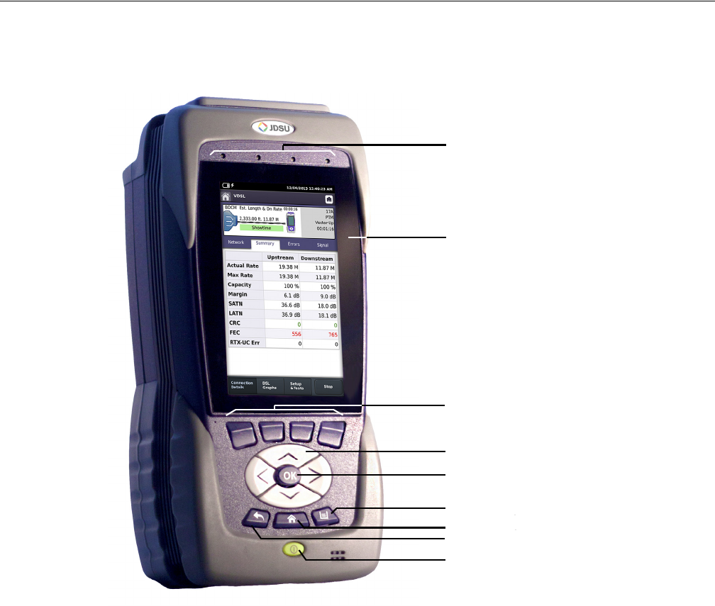
The controls and LEDs on the front panel, shown in Figure 2, are used to operate the
OneExpert DSL, set up tests, and view data.
The following paragraphs describe each of the controls and LEDs on the front panel.
Figure 2 OneExpert DSL front panel
LCD
Status LEDs
Arrow keys
Power key
OK key
Cancel system key
Home system key
Function keys
Tray system key

Chapter 2 Quick Tour
Exploring the front panel
OneExpert DSL User’s Guide
April 2014 22052280, Revision 001 7
Status LEDs
These indicators report the status of the OneExpert DSL. The function of each LED is described in
Tab le 2 .
LCD
The LCD is a touchscreen that operates similar to a mobile device (such as an iPad or similar
Android device), where you swipe to go to the next page or zoom in/out with pinching or opening
your fingers.
Function keys
Use to select screen-specific options or to select pop-up menus associated with each key.
Table 2 Status LEDs
LED Function
Sync Reports the status of modem synchronization.
– Blinking green indicates that the modems are training.
– Solid green indicates that the modems are synchronized (reached Showtime).
Network Indicates the status of network connectivity.
– Blinking green indicates that the unit is acquiring an IP address.
– Solid green indicates frames an IP address has been acquired.
– Blinking amber indicates a timeout - the unit was unable to acquire an IP address.
– If the Frame LED is not illuminated, the network is not active (either the unit is not
connected or it is logged off.
NOTE: The Sync and Network LEDs alternately blink green when in sleep mode (power saving mode).
Error Solid red indicates error and alarm conditions. The type of error varies depending on
the application.
Batt A multi-color LED that indicates the battery status.
– Solid green indicates that either the battery charge is higher than 30%, or that an
external source is powering the unit.
– Solid red indicates that the battery charge is critically low, less than 10%.
– Solid amber indicates that the battery is getting low, the charge is between 10% and
30%.
Charge A multi-color LED located next to the charger connector that indicates the charge sta-
tus.
– Solid green indicates that charging is complete.
– Slow flashing red indicates that the battery charge is critically low, less than 10%.
– Fast flashing red indicates that the charging was suspended due to a fault and user
intervention is necessary (for example, the wrong charger is attached).
– Solid red indicates that the charging was suspended due to overheating. The unit
can continue to run, no user intervention necessary.
– Solid amber indicates that the battery is charging.
Chapter 2 Quick Tour
Exploring the bottom panel
OneExpert DSL User’s Guide
822052280, Revision 001 April 2014
Arrow keys
Use the arrow keys to navigate through menu selections.
OK key
The OK key is used to accept a changed setting or to proceed to the next menu.
System keys
Under the Navigation arrow keys, there are three system keys:
Power key
Use the power key to turn the OneExpert DSL power on or off. Press and hold until the unit beeps
to turn on or off.
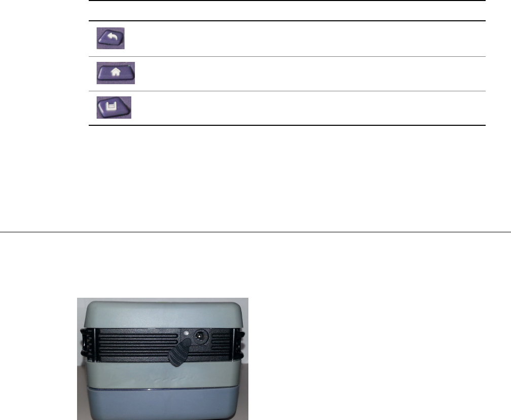
Exploring the bottom panel
The OneExpert DSL +12VDC connector is located on the bottom end of the instrument. This
connector is used to power the OneExpert DSL and to charge the lithium battery inside.
Key Description
Back/Cancel – exit a menu or to go back to the previous menu.
Home – Return to the main/home screen
Tray – Launch the Tray menu. From the Tray Menu you can save test
reports, turn on/off Bluetooth, or enable/disable Remote Operation.
Figure 3 OneExpert DSL bottom panel
Chapter 2 Quick Tour
Exploring the connector panel
OneExpert DSL User’s Guide
April 2014 22052280, Revision 001 9
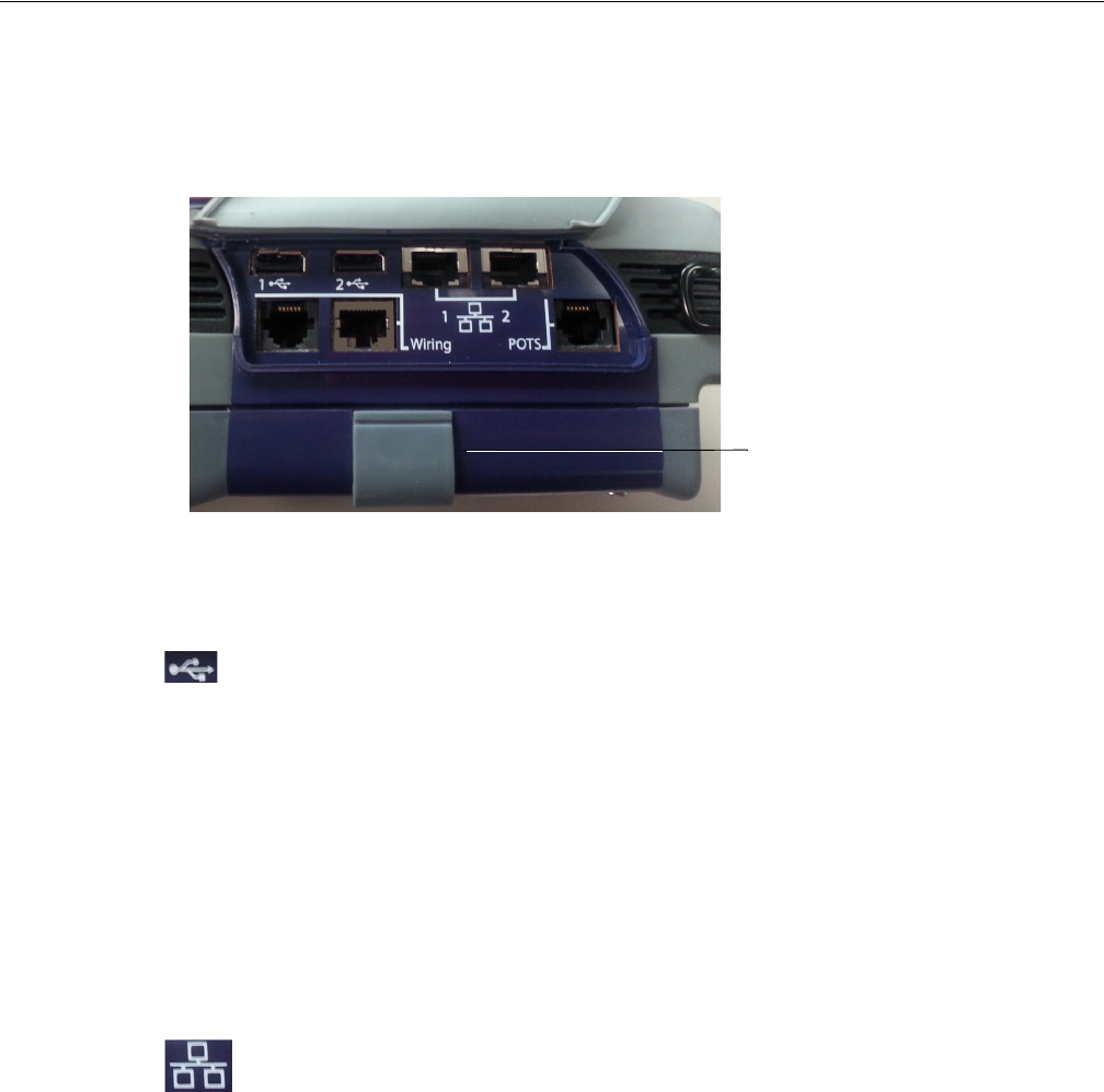
Exploring the connector panel
The connector panel is located on the right side of the instrument and under a rubber flap. When
the connectors are not being used, place the rubber flap over the connector panel to keep out dust
and rain. Use the connector panel to connect the OneExpert DSL to the line under test. Figure 4
shows the connector panel.
USB connectors
The USB connectors are used for connecting Smart IDs, exporting test results to a flash drive, or
for performing firmware upgrades from a flash drive.
POTS connector
The POTS connector is used for:
• HPNA testing on twisted pair
• POTS testing
Network connectors
Two Ethernet/Network ports are used to connect to Ethernet networks which allows synchronizing
with StrataSync, upgrading software, and remotely connecting to the OneExpert DSL.
ERJ45 Wiring connector
The RJ45 Wiring connector is used for:
• Ethernet Ping
• RJ45 wire ID
Figure 4 OneExpert DSL connectors right panel
xDSL connector

Chapter 2 Quick Tour
Exploring the connector panel
OneExpert DSL User’s Guide
10 22052280, Revision 001 April 2014
• RJ45 toning
• Wire mapping to smart remote
RJ11 Wiring connector
The RJ11 Wiring connector is used for:
• RJ11 wire ID
• RJ11 toning
• Coax wire ID (with supplied adapter cable)
• Coax toning (with supplied adapter cable)
• RJ11 wire mapping to smart remote
• Volt/Ohm measurements
DSL connector
The DSL connector, located on the bottom module, is used for:
• Testing VDSL or ADSL on twisted pair cable
Rings
The rings on the corners of the instrument can be used to attach a carry strap.
WARNING: ELECTRICAL SHOCK
Electrical shock may result in serious injury or death. Use care when connecting to telecommu-
nications circuits, to be sure that you do not come in contact with exposed conductors or power
mains. Connect TNV signals to TNV ports only.
CAUTION: FIRE HAZARD
To reduce the risk of fire, use only 26 AWG or larger telecommunications line cord between the
DSL connector and the wall.
NOTE: ELECTROSTATIC DISCHARGE IMMUNITY
When using an Ethernet crossover cable, JDSU recommends using a shielded crossover cable
for the best immunity to electrostatic discharge (ESD).
Chapter 2 Quick Tour
Exploring the top panel
OneExpert DSL User’s Guide
April 2014 22052280, Revision 001 11
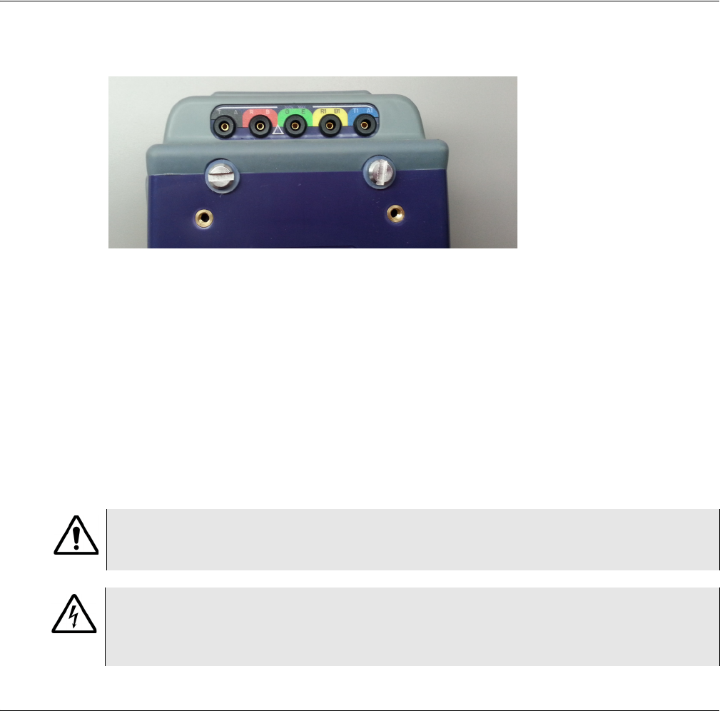
Exploring the top panel
The Copper connectors are located near the top panel.
The copper connectors are used for:
•Multimeter
– AC volts
– DC volts
•TDR
• Opens (distance) and capacitance
•Balance
• Load coil detect
•POTS
Navigating the user interface
The user interface of the OneExpert DSL is designed to be intuitive and easy to use. The LCD is a
touchscreen that operates similar to a mobile device (such as an iPad or similar Android device),
where you swipe to go to the next page or zoom in/out with pinching or opening your fingers.Using
the interface, you can view test results, set up the OneExpert DSL, and configure test parameters.
Figure 5 OneExpert DSL top panel
CAUTION: INSTRUMENT DAMAGE
Connecting to circuits with voltage higher than 300V, compared to ground, may damage the
internal components. Connect only to circuits with less than 300V.
WARNING: ELECTRICAL SHOCK
Electrical shock may result in serious injury or death. Use care when connecting to telecommu-
nications circuits, to be sure that you do not come in contact with exposed conductors or power
mains. Connect TNV signals to TNV ports only.
Chapter 2 Quick Tour
Navigating the user interface
OneExpert DSL User’s Guide
12 22052280, Revision 001 April 2014
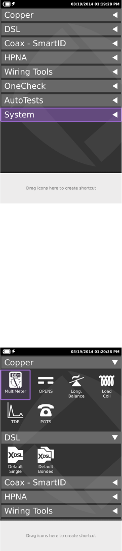
When you power up the OneExpert DSL, the user interface appears (see Figure 6).
This is the main menu. The menu selections change depending on options enabled on your instru-
ment. If a job has been activated (using the job manager), the circuit, ticket, and tech ID appear
above the system keys.
The header area provides battery status, indicates whether the adapter is plugged in, and displays
the date and time.
Each main item is a collapsible menu.
Figure 6 User interface - main menu
Figure 7 User interface - example of collapsible menus
Chapter 2 Quick Tour
Navigating the user interface
OneExpert DSL User’s Guide
April 2014 22052280, Revision 001 13
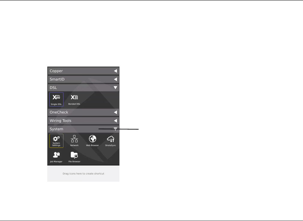
To expand a menu
Do one of the following:
• Touch the triangle on the right (the triangle rotates from pointing left to pointing down)
• Use the arrow navigation keys to highlight the desired menu item (System is highlighted in
Figure 6 above) and then press the OK key.
To select a menu option
Do one of the following:
• Touch the item
• Use the arrow navigation keys to highlight the desired menu item and then press the OK key.
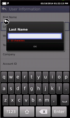
Some menus may require you to enter text or numbers (for example, test settings or user informa-
tion). The process is similar to data entry on a mobile device.
To enter text or numbers
1Touch the desired item.
A data entry box appears.
2Tap in the box.
A keypad appears on the screen.
3Use keypad to enter the data.
– To switch from letters to numbers, use the button in the lower left (123 or ABC).
– On the alphabetic keypad, the second key, the up arrow, is the shift key.
– On the numeric keypad, the second key (1/2) allows you to move among multiple numeric
screens.
– The left pointing arrow with the x in it is the backspace key.
Chapter 2 Quick Tour
Navigating the user interface
OneExpert DSL User’s Guide
14 22052280, Revision 001 April 2014
4Touch the enter/return key (the fourth system key) on the screen keypad or press the OK key.
If you have a test or function that you use frequently, you can make it a shortcut.
To create a shortcut
Touch and hold the icon for the function and then drag it to the bottom of the screen to create a
shortcut. You can create up to four shortcuts.

OneExpert DSL User’s Guide
April 2014 22052280, Revision 001 15
3
Chapter 3
Utilities
This chapter describes utilities found in the System menu and the Tray menu. These include system
settings, upgrading software, specifying user information, saving test reports, capturing a screen
shot, and other tasks. Topics discussed in this chapter include the following:
•“Specifying system settings” on page 16
•“Setting the date and time” on page 17
•“Remotely operating a OneExpert DSL unit” on page 18
•“Enabling Bluetooth” on page 20
•“Configuring international settings” on page 20
•“Updating the instrument software over a network” on page 21
•“Updating software using USB Flash” on page 21
•“Viewing unit options and revisions” on page 22
•“Restoring factory defaults” on page 22
•“Changing screen settings” on page 22
•“Setting the power off delay” on page 23
•“Specifying user information” on page 23
•“Specifying network profiles” on page 24
•“Browsing the web” on page 25
•“Synchronizing to the StrataSync server” on page 27
•“Managing jobs” on page 28
•“Managing files” on page 29
•“Using the tray menu” on page 31
•“Saving results to a job” on page 31
•“Saving a report” on page 32
•“Capturing a screen shot” on page 32
•“Setting the volume” on page 33
Chapter 3 Utilities
Accessing the System menu
OneExpert DSL User’s Guide
16 22052280, Revision 001 April 2014
Accessing the System menu
The System menu is available on the main menu screen.
To access the System Settings menu
• From the main menu, touch the System menu item.
The collapsible menu opens (the triangle rotates from pointing left to pointing down).
Specifying system settings
Using the System Settings menu, you can set the date and time, configure port settings, adjust print
settings, adjust remote control settings, and configure international settings.
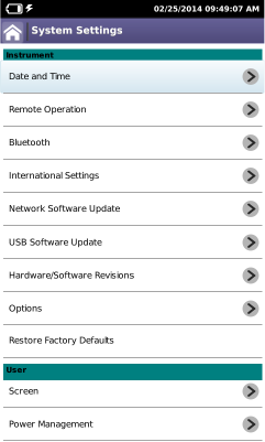
1From the System menu (Figure 8 on page 16), touch the System Settings button.
Figure 8 The System menu
System menu
Chapter 3 Utilities
Specifying system settings
OneExpert DSL User’s Guide
April 2014 22052280, Revision 001 17
The System Settings menu appears.
Setting the date and time
The first selection on the System Settings menu is Date and Time. The OneExpert DSL has an
internal clock that you can set to provide accurate time stamps for test results.
The following procedure describes how to set the date and time.
To set the date and time
1From the System Settings menu, select Date and Time.
The Date and Time Settings menu appears.
2Set the time by touching Time, turning the dials, and then touching Set.
3Set the date by touching Date, using the arrows to set the month and year, touching the day
on the calendar, and then touching Set.
4Specify the Date Format by touching Date Format and then selecting either MM/DD/YYYY or
DD/MM/YYYY format.
5Specify the Time Format by touching Time Format and then selecting either 12 Hour or 24
Hour.
6To change the Time Zone, touch Time Zone and then select your time zone.
7If Daylight Savings Time (DST) is used in your area, touch DST Used to add a check mark.
8If Time Synchronization is needed, touch Time Synchronization and then select NTP. If not
needed, set Time Synchronization to None. Network Time Protocol (NTP) synchronizes your
system clock with a central time server.
Chapter 3 Utilities
Specifying system settings
OneExpert DSL User’s Guide
18 22052280, Revision 001 April 2014
9If you selected NTP Time Synchronization specify the following:
–NTP Server Address type (IPv4 Address, IPv6 Address, DNS Name)
–NTP Server (the address of the server that the instruments gets the time from, for
example 0.us.pool.ntp.org)
The date and time are set.
Remotely operating a OneExpert DSL unit
The optional Remote Operation features allows you to access the OneExpert DSL user interface
from a PC or laptop computer through a virtual network connection (VNC), connecting over an
Ethernet interface.
To use this feature, you must have a VNC viewer program on the PC, the OneExpert DSL must be
connected to the same network as the PC or laptop, and you must know the IP address of the
OneExpert DSL.
Establishing a VNC connection involves the following tasks:
– Establishing an Ethernet LAN connection between the OneExpert DSL and a PC or laptop
– Enabling Remote Operation using VNC
– Control the OneExpert DSL using a PC keyboard
Each of these operations is described in the following sections.
Establishing an Ethernet connection
You must have an Ethernet LAN cable to establish an Ethernet connection to the OneExpert DSL.
To establish an Ethernet connection to the OneExpert DSL
1Using an Ethernet cable, connect the OneExpert DSL to same Ethernet LAN as the PC or
laptop you will use for the VNC:
aConnect one end of the Ethernet cable to the OneExpert DSL Ethernet connector located
on the side panel (see Figure 4 on page 9).
bConnect the other end of the Ethernet cable to the LAN.
2From the System Settings menu, select Remote Operation, and then do the following:
aCheck Enable VNC Server.
bIf you wish to specify a new password to access the OneExpert DSL, touch VNC Pass-
word, click in the text box, and then enter a new password.
3Configure the Network Profile settings to match your LAN settings.
aFrom the System Settings menu, select Network.
If you are connected to the network and the Network is active, the profile settings appear
in the box at the top of the menu.
bIf the settings don’t match your LAN touch Edit Profile and then modify the settings as
needed.

Chapter 3 Utilities
Specifying system settings
OneExpert DSL User’s Guide
April 2014 22052280, Revision 001 19
The Ethernet connection is established.
Viewing the device interface on the PC
After you have established an Ethernet connection, you must launch the VNC program to view the
device interface.
To view the device interface on the PC
1Launch the VNC viewer on the PC.
2In the viewer’s server address field, type the OneExpert DSL's IP address, and then select
OK.
A password entry box appears.
3Enter the VNC password (found on the Remote Operation menu) and then click OK or press
Enter.
The OneExpert DSL user interface appears in the VNC viewer.
4To use a PC or laptop keyboard with the OneExpert DSL’s user interface, see “Using a PC
keyboard” on page 19.
5If the message, “Failed to connect to server” appears, the VNC viewer was not able to commu-
nicate with the OneExpert DSL. If this happens, try the following solutions:
– Make sure you are using the correct IP address for the OneExpert DSL.
– From the PC or laptop, ping the OneExpert DSL IP address to verify the network link is
working. If the link is not working, restart the OneExpert DSL and repeat step 1 through
step 2.
Using a PC keyboard
After you have connected to the OneExpert DSL from a laptop or PC using the VNC viewer, you
can use the computer’s mouse or keyboard to control the OneExpert DSL. Tab le 3 shows how the
PC/laptop keys map to the OneExpert DSL keypad.
VNC availability
The VNC program can control the following functions:
Table 3 PC/laptop to OneExpert DSL key map
PC/Laptop key OneExpert DSL Keys
F1 through F4 Correspond to the OneExpert DSL system keys
F5 Home
F6 Tray menu
F7 AutoTest
Escape Cancel
Enter OK
Chapter 3 Utilities
Specifying system settings
OneExpert DSL User’s Guide
20 22052280, Revision 001 April 2014
In Ethernet TE, you can do a ping, trace route and similar data tests, but cannot change any data
settings.
In DSL, you can perform modem emulate tests with Data mode off.
Ending a remote operation session
To end a remote operation session, either exit the VNC session on the PC/laptop or turn the
OneExpert DSL off and then on again (power cycle).
Enabling Bluetooth
The Bluetooth option allows communication with a mobile device.
To enable Bluetooth
1From the System Settings menu, select Bluetooth.
2Touch the box next to Enabled. A check mark appears.
You can now use the OneExpert DSL with a mobile device. See “Using the OneExpert DSL with a
mobile device” on page 73
To disable Bluetooth, touch the box to remove the check mark.
Configuring international settings
The International Setting menu is used to select the language, units of measurement, and other
international settings. There are two ways to select international settings:
– Selecting a preset country. These selections automatically configure the settings as appro-
priate for that country.
– Configuring each setting individually. If you are not in one of the preset countries, or if the
settings aren’t appropriate for your situation, you can configure each setting individually.
These settings are stored when the unit is turned off.
To configure international settings
1From the System Settings menu, select International Settings.
The International Settings menu appears.
2Optional. Select Country to select a preset country.
Selecting a specific country will automatically change the settings as appropriate for that
country. For example, selecting Spain will automatically set the language to Spanish, unit of
distance to meters, unit of temperature to celsius, noise filter to CCITT, cable size to millime-
ters, TDR units to m/us, and numerical separator to a comma.
3Change the settings as appropriate for Language, Measurement System, Temperature Units,
Time Zone, and Cable Terminology.
To change the settings, touch the menu item, and then select an item from the list.
The international settings are configured.
Chapter 3 Utilities
Specifying system settings
OneExpert DSL User’s Guide
April 2014 22052280, Revision 001 21
Updating the instrument software over a network
The OneExpert DSL software can be upgraded in the field using the Ethernet Network port.
To update over an intranet or network
1Obtain the IP or FTP address where the software file is located, as well as the User Name and
Password.
2Connect the OneExpert DSL to the AC charger adapter to ensure an uninterrupted supply of
power during the update.
3From the System Settings menu, select Network Software Update.
4Touch Update URL and then enter the complete IP address where the file is located.
5Touch Username and then enter the User Name for the address.
6Touch Password and then enter the Password for the address.
7Select the Update system key.
The update status is displayed on the screen.
The unit powers down when done.
Updating software using USB Flash
The OneExpert DSL software can be upgraded in the field using the USB port.
To update over USB
1Connect the OneExpert DSL to the AC charger adapter to ensure an uninterrupted supply of
power during the update.
2Connect a USB flash drive to the USB connector on the right panel.
The OneExpert DSL will auto-detect the USB drive. This USB should contain the update file.
3From the System Settings menu, select Network Software Update.
WARNING: ELECTRICAL SHOCK
Electrical shock may result in serious injury or death. Be sure the AC adapter is connected to the
correct voltage mains. Do not use outdoors or in wet locations. Use only the AC adapter supplied
with the tester.
NOTE
In order for the update to work, you must enter the complete address, including the server and
directory. For example, ftp://ftp.<your company>.com/<directory name>
NOTE:
The update will take several minutes.
WARNING: ELECTRICAL SHOCK
Electrical shock may result in serious injury or death. Be sure the AC adapter is connected to the
correct voltage mains. Do not use outdoors or in wet locations. Use only the AC adapter sup-
plied with the tester.

Chapter 3 Utilities
Specifying system settings
OneExpert DSL User’s Guide
22 22052280, Revision 001 April 2014
4Touch USB Update Path and then select the update file.
5If the update doesn’t start automatically after selecting the file, select the Update system key.
The update status is displayed on the screen.
The unit powers down when done.
Viewing unit options and revisions
The following procedure describes how to view unit options and revisions.
To view unit revisions and options
1From the System Settings menu, select Hardware/Software Revisions.
The revisions of the internal components and the software versions appear. The unit’s unique
ID number also appears on this screen. You will need the unit ID if you are adding options to
the unit.
2From the System Settings menu, select Options.
A list of the unit’s options appear and reports whether the option is enabled.
Viewing revisions and options is complete.
Restoring factory defaults
The following procedure describes how to reset the OneExpert DSL to factory default settings.
To reset to factory defaults
1From the System Settings menu, select Restore Factory Settings.
2At the prompt, press the OK key to restore the factory default settings. Press the Cancel to
exit the prompt.
Changing screen settings
The Screen Settings menu allows you to adjust the brightness of the backlight and set the backlight
timeout.
Adjusting the backlight brightness
To adjust the brightness of the backlight
1From the System Settings menu, select Screen.
NOTE:
The update will take several minutes.
NOTE:
Restoring factory defaults resets test application settings and system settings (such as bright-
ness, contrast, and volume), and powers down the unit.

Chapter 3 Utilities
Specifying system settings
OneExpert DSL User’s Guide
April 2014 22052280, Revision 001 23
2From the Screen Settings menu, select Backlight.
3Change the brightness level using the left or right arrow key.
The brightness is set.
Setting the backlight timeout
The backlight duration specifies the amount of idle time (no key presses and no line activity) to wait
before the dimming the backlight to conserve battery life.
To set the backlight duration
1From the System Settings menu, select Screen.
2From the Screen Settings menu, select Backlight Timeout.
3Select a timeout.
The backlight duration is set.
Setting the power off delay
The power management settings menu allows you to select whether to automatically turn off the
unit to conserve battery life, and set the time to wait before the backlight dims (“Setting the backlight
timeout” on page 23).
To set the power off delay
1From the System Settings menu, select Power Management.
2From the Power Management menu, select Power Off Delay.
3Select the amount of idle time to wait before powering the unit off.
Idle time refers to no key presses and no line activity. So, if you set the power off delay to 5
minutes and then begin a 15 minute test, the unit will not power down during the test because
there is line activity.
The auto power down parameters are set.
Specifying user information
The User Information menu allows you to enter specific information related to the technician using
the OneExpert DSL. This includes the technician name, technician ID, location (city, county, state,
country, postal code, and garage), and the account ID. This information is used when synchronizing
with the StrataSync server.
NOTE:
The OneExpert DSL will not automatically power down when connected to the AC adapter.
NOTE:
A valid account ID must be entered in order to synchronize with the StrataSync server.

Chapter 3 Utilities
Specifying network profiles
OneExpert DSL User’s Guide
24 22052280, Revision 001 April 2014
To specify user information
1From the System Settings menu, select User Information.
2Specify the user’s first and last name, workgroup, company, email address, and other infor-
mation.
3Press the Back/Cancel function key to exit the menu.
Specifying network profiles
The network button is used to specify and store network profiles and to enable or disable a network
profile.
To specify network profiles
1From the System menu (Figure 8 on page 16), touch the Network button.
A list of network profiles appears. If you are currently connected to a network, that profile will
appear at the top of the menu.
2To modify a profile
aHighlight the profile and then select Edit Profile.
bSelect Profile Name and then enter a name for the profile.
A descriptive name such as “Downtown IPv4/IPv6 Stateless” allows easier recognition by
other technicians (vs “Garage1” or “Branch7”).
cSelect Network Mode and then specify the network mode: IPv4, IPv6, or IPv4/IPv6 Dual
Stack.
Depending on the Network Mode, you may have one or more additional settings to
specify.
dIf you selected IPv4, do the following:
–Select IPv4 Address Mode and then select Static or DHCP.
If you selected DHCP, you are finished.
– If you selected Static address mode, specify the following:
IP Address (The OneExpert DSL's IP address to the access the provider network),
Netmask (IP devices use a netmask IP address to determine if IP packets are to be
routed to other networks or sub-networks)
Gateway (The OneExpert DSL OneExpert DSL's gateway address. When an IP device
has determined that a packet is not addressed to it or devices on the same sub-network
(subnet), it sends all such packets to the gateway address for further routing to the
correct address.
DNS Server (If the IP Mode is Static enter the address of the DNS server.)
eIf you selected IPv6, do the following:
–Select IPv6 Address Mode and then select Manual, Stateles or DHCPv6.
If you selected DHCPv6, you are finished.
– If you selected Stateless address mode, specify the following:
IPv6 DNS Address Mode (how the OneExpert DSL obtains the DNS address) and then
select Manual or DHCPv6.

Chapter 3 Utilities
Browsing the web
OneExpert DSL User’s Guide
April 2014 22052280, Revision 001 25
If you selected DHCPv6, you are finished.
If you selected Manual, enter the IPv4 DNS Server address (the address of the DNS
server).
– If you selected Manual address mode, specify the following:
IPv6 Global Address (The OneExpert DSL's IPv6 address to the access the network).
IPv6 Subnet Prefix Length (specify the length of the subnet prefix, from 0 to 128).
IPv4 Gateway (The IPv4 gateway address)
IPv6 DNS Address Mode (how the OneExpert DSL obtains the DNS address) and then
select Manual or DHCPv6.
If you selected DHCPv6, you are finished.
If you selected Manual, enter the IPv4 DNS Server address (the address of the DNS
server).
fIf you selected IPv4/IPv6 Dual Stack, do the following:
–Select IPv4 Address Mode and then specify settings as described in step d above.
–Select IPv6 Address Mode and then specify settings as described in step e above.
gPress the Back/Cancel navigation key to return to the Profiles screen.
The network profile is updated.
3To disable a network profile, highlight the profile, and then touch the Network Off button. The
profile is disabled. NOTE: This only disables the profile from being loaded onto the unit; it will
not disable the actual network.
Browsing the web
With the web browser feature, you can provide visual proof to customers that a circuit is correctly
provisioned all the way to the Internet. The browser works over both DSL and Ethernet interfaces,
allowing you to surf the web from the customer's NID or demarcation point using only the
OneExpert DSL. For DSL applications, the browser is a separate mode that allows you to connect
to any public web site on the Internet through an internet service provider. The browser can also be
purchased as a general global application for use with the Ethernet port.
Because the browser’s primary purpose is to demonstrate connectivity, it does not have all the
capabilities of typical web browsers, such as Internet Explorer or Netscape Navigator. The web
browser has the following limitations:
– The browser does not cache web pages. The OneExpert DSL does not have sufficient memory
to cache web pages. Each time a page is selected, the OneExpert DSL re-loads the page.
– The browser does not currently support data entry through the browser. For example, you
cannot log into a web mail account.
– The browser does not currently support Java applets, and will not display web pages written in
Java. Sites optimized for quick downloads, such as DSLReports.com, are not supported
because they are based on Java.
The following sections in this chapter describe how to access and use the web browser.
Chapter 3 Utilities
Browsing the web
OneExpert DSL User’s Guide
26 22052280, Revision 001 April 2014
Accessing the web browser
Like IP ping, you must have an established underlying network connection, such as PPP over
Ethernet, before you can use the browser. After you have a successful network connection, the
OneExpert DSL’s Network LED illuminates green. If the LED is red, the underlying connection is not
ready, and the web browser (and IP ping) will not work.
To access the web browser
• From the System menu (Figure 8 on page 16), touch the Web Browser button.
The web browser display appears.
Navigating the browser
You can navigate the browser as you would with a mobile device, with tapping in text boxes to dis-
play the keypad and enter the data, swiping your fingers to scroll, touching links to select them,
and so on. In addition, you can connect a USB mouse or a USB keyboard/mouse combination to
the OneExpert DSL to navigate the web browser as you would with a desktop computer. Going
back or forward one page
Opening a web page
There are two ways to open a web page.
– Enter the address - tap the address box, and then use the keypad on the screen to enter the
address.
– Use a bookmark - touch the Bookmarks button and then select a bookmark.
Adding bookmarks
If there is a specific page that you would like to view or if you visit a site frequently, you can book-
mark it. There are six bookmark slots available: one for your Home URL and five others.
To add bookmarks
1On the main Web Browser page, touch the Bookmarks button.
2Select a bookmark and then enter the URL.
Exiting the browser
When you are finished demonstrating internet access to the user, you should exit the browser.
To exit the browser
1Press the Home function key or tap the home icon on the browser menu.
The browser closes.

Chapter 3 Utilities
Synchronizing to the StrataSync server
OneExpert DSL User’s Guide
April 2014 22052280, Revision 001 27
Synchronizing to the StrataSync server
StrataSync® is a hosted, cloud-based software application that provides JDSU instrument asset,
configuration, and test-date management. StrataSync manages inventory, test results, and perfor-
mance data anywhere with browser-based ease and improves technician and instrument efficiency.
Features include the following:
• Pushing certain configuration settings to the OneExpert DSL
• Adding and/or removing software options on the OneExpert DSL
• Updating the software on the OneExpert DSL
• Updating the software on the modem
• Receiving certain configuration setting from the OneExpert DSL
• Tracking ownership of the OneExpert DSL
To obtain the latest configuration settings, software options and updates, and ownership registration
information, the OneExpert DSL can synchronize with a JDSU server via the internet. The synchro-
nization also stores any user files saved on the unit to the StrataSync server. This procedure should
be undertaken immediately upon receipt of the unit and on a regular (daily) basis thereafter to
ensure that the unit is as up-to-date as possible and to allow all user information to be backed up.
Before attempting to synchronize with StrataSync, please confirm your server settings with your
manger or your company's IT organization.
To sync with StrataSync
1If you haven’t already done so, specify the user information on the User Info menu (see
“Specifying user information” on page 23). A valid account ID must be entered in order to
synchronize with the StrataSync server.
2From the System menu (Figure 8 on page 16), touch the StrataSync button.
The StrataSync settings menu appears.
3Specify the connection and server settings.
Setting Description
Connection Specify which connector to use - 10/100 Ethernet or xDSL.
Connection Type Specify how to connect to the server.
– Lookup – Use an intermediate server that will automatically identify
(“lookup”) the specific StrataSync server to be addressed. The lookup
server connection type is typically used when there are multiple Strata-
Sync servers in the user’s corporate footprint.)
– Direct – Use a direct reference to a specific StrataSync server)
NOTE: The OneExpert DSL uses HTTPS (secure HTTP) to connect to the
server.
Server Method Specify how to refer to the server (this applies for both connection types)
– Address Server by IP (192.168.0.1)
– Address Server by Name (myServer)
Lookup Server Port Enter the server port number.
Chapter 3 Utilities
Managing jobs
OneExpert DSL User’s Guide
28 22052280, Revision 001 April 2014
4Touch the Start button.
As the process runs, the sync state is displayed in the lower left.
• Upon synchronization with the StrataSync server, the unit will send to the server the following
information:
– The unit’s serial number.
– The unit’s hardware information - constituent assemblies and their revision levels.
– The unit’s MAC address.
– The unit’s User settings - name (user/technician) and ID.
If the configuration information contained on the server is newer than that on the unit, the
server will be considered to be the most up-to-date.
• The server will then send any files to the unit being synchronized that it determines are newer
than those on the unit.
• The unit will then send any Reports, Configuration profiles, screen shots, etc. that have been
saved on the unit since the last configuration.
• The server then applies any applicable Options to the unit.
• Lastly, if any upgrades are available, the user will be informed of their availability and asked to
verify their desire to receive the upgrade.
When synchronization is complete, the Status will indicate “Sync Complete”. The unit may be
disconnected from the server.
Managing jobs
The Job Manager is used to associate test results from different applications (for example HPNA,
Optical Power Meter, DSL, and Copper Pair Check) to a single job. If any jobs have been saved,
they appear in the list. The Job Manager allows you to setup a new job, edit an existing job, activate
a job, or delete a job.
To manage jobs
1From the System menu (Figure 8 on page 16), touch the Job Manager button.
If any jobs have been created, they will be listed on the screen.
2To create a new job, touch the New button, and then enter the work ticket, BAN, and UUID.
3To edit an existing job, highlight the job you wish to modify, select the Actions system key,
and then select Edit Job.
4To select multiple jobs (to activate, export, or delete)
Lookup Server Name Enter the server name.
Setting Description
NOTE:
If an Option Code was entered as a part of synchronization, power must be cycled to the unit to
complete the process and initialize the option.

Chapter 3 Utilities
Managing files
OneExpert DSL User’s Guide
April 2014 22052280, Revision 001 29
aTouch the Manage button. The jobs list appears.
bTouch to select the jobs. A check mark appears next to the job.
cTouch the Manage button to return to the Job Manager screen.
5To activate a job, highlight the job to activate, and then press the Activate system key.
“Active” appears on the job listing.
6To export a job, highlight the job you wish to export (or highlight multiple, as described in
step 4), select the Actions system key, and then select Export. The job will be exported as a
XML file.
7To delete a job, highlight the job you wish to delete (or highlight multiple, as described in
step 4), select the Actions system key, and then select Delete. A confirmation box appears.
Select Yes.
Associating results to a job
To associate results to a job
1After running a test, touch the Setup & Tests button.
2Select Save.
The file is saved.
Managing files
The OneExpert DSL file browser is used to open, rename, copy, or delete saved result files or
screen shots.
To manage saved result files
1From the System menu (Figure 8 on page 16), touch the File Browser button.
The File Manager screen is displayed with all saved results.
2Use the up and down arrow keys to move among folders and files.
NOTE:
Once a job has been successfully uploaded to the job server, the job is deactivated and locked
(i.e., cannot edit the ticket number or other fields). The next job must be a new ticket. This
ensures that the correct test data is being saved and exported with the correct job. The check
box next to the job will be greyed out.
NOTE:
If you have a USB flash drive connected to the OneExpert DSL, there is a USB File Browser
button on the System menu, in addition to the File Browser. Both browsers operate in the same
manner.
Chapter 3 Utilities
Managing files
OneExpert DSL User’s Guide
30 22052280, Revision 001 April 2014
Opening files
To open a file
1Using the up and down arrow keys, highlight the desired file.
2Press the OPEN system key.
The contents of the file are loaded to the screen for viewing.
Renaming files
To rename a file
1Using the up and down arrow keys, highlight the desired file.
2Press the Rename system key.
The Rename screen is displayed.
3Touch the file name in the box.
A keypad appears on the screen
4Touch the enter/return key on the screen keypad or press the OK key.
The new file name appears in the File Manager screen.
Deleting files
To delete files
1Using the up and down arrow keys, highlight the desired file.
2Press Delete system key.
The files are erased.
Copying and pasting files
To copy files
1Using the up and down arrow keys, highlight the desired file, and then press the File Options
system key.
2Do one of the following:
–Select Copy, navigate to another folder or drive, press the File Options system key, and
then select Paste.
The file is pasted and the File Manager screen appears.
– Select either Copy to USB if you are using File Browser or Copy to Internal if you are
using the USB File Browser.
The file is copied and the File Manager screen appears.

Chapter 3 Utilities
Using the tray menu
OneExpert DSL User’s Guide
April 2014 22052280, Revision 001 31
Uploading files (FTP/HTTP)
To upload files
1Using the up and down arrow keys, highlight the desired file.
2Press the File Options system key, and then select Upload FTP/HTTP.
The Upload settings appear.
3Specify the Upload URL, Username, and Password.
4Touch Apply.
The upload starts.
When the upload finishes, a message appears stating that the selected files were uploaded.
Press OK to close the message.
Using the tray menu
The tray menu, shown in Figure 9, can be accessed either by pressing the Tray function key or by
swiping downward from the top of the LCD.
Saving results to a job
If you are currently running a test, you can save test results to a job.
To save results to a job
• Access the Tray menu and then touch Save to Job.
The current test results are saved to the job.
You must have an active job and active test. The text will be gray if there is no active job.
Figure 9 Tray menu
Chapter 3 Utilities
Using the tray menu
OneExpert DSL User’s Guide
32 22052280, Revision 001 April 2014
Saving a report
If you are currently running a test, you can save test results as a report.
To save a report
1Access the Tray menu and then touch Save Report.
You must have an active test or the text will be gray.
A Save Report window appears.
2Enter the name of the report.
3Specify the format for the report.
4If there is an active job, select whether to include the job info in the report. This selection only
appears if a job is active.
5Select whether to view the report after saving.
6Touch Save.
The current test results are saved as a report.
Viewing a report
If you have a saved report, you can view the report.
To view a report
1Access the Tray menu and then touch View Report.
You must have a saved report or the text will be gray.
A View Report window appears, showing all of the saved reports.
2Select a report to view.
The report appears on the screen.
Capturing a screen shot
In addition to or instead of a report, you can capture an image of the current screen.
To capture a screen shot
• Access the Tray menu and then touch Screen Shot.
The PNG file is saved to the internal file manager.
Disabling the network
The tray menu allows you to disable the network profile.
To disable the network
• Access the Tray menu and then touch Network: Disabled.
Chapter 3 Utilities
Using the tray menu
OneExpert DSL User’s Guide
April 2014 22052280, Revision 001 33
NOTE: This only disables the profile from being loaded onto the unit; it will not disable the
actual network.
Enabling Bluetooth
The tray menu offers a shortcut to enable or disable Bluetooth connection.
To enable or disable Bluetooth connection
• Access the Tray menu and then touch Bluetooth.
To verify whether Bluetooth is enabled, go to the System Settings menu and view the Blue-
tooth menu. A check mark appears when Bluetooth is enabled.
Setting the volume
The tray menu allows you to control the instrument volume.
1Access the Tray menu and then touch Volume.
The volume scroll bar appears.
2Either touch the + / - buttons on the screen or swipe your finger across the bar to move the
line on the bar, adjusting the volume.
Chapter 3 Utilities
Using the tray menu
OneExpert DSL User’s Guide
34 22052280, Revision 001 April 2014

OneExpert DSL User’s Guide
April 2014 22052280, Revision 001 35
4
Chapter 4
DSL Testing
This chapter provides task-based instructions for using the OneExpert DSL to gather DSL (VDSL,
ADSL2+/2/1) statistics and verify connectivity. Topics discussed in this chapter include the
following:
•“About xDSL testing” on page 36
•“Selecting the test mode” on page 36
•“Specifying test settings” on page 37
•“Testing the physical layer” on page 41
•“Testing line quality” on page 41
•“Terminating the loop (SELT)” on page 41
•“Performing a ping test” on page 42
•“FTP throughput testing” on page 42
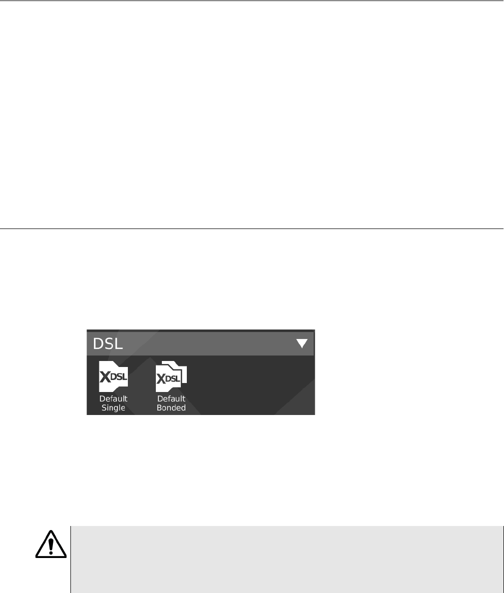
Chapter 4 DSL Testing
About xDSL testing
OneExpert DSL User’s Guide
36 22052280, Revision 001 April 2014
About xDSL testing
The purpose of the DSL tests are to assess the quality of the xDSL signal and to verify the xDSL
rates achieved at various points in the network.
The tests involve three main steps:
• selecting the test mode and specifying test settings
• connecting to the line
• running the tests
The ADSL/VDSL Bonding Option, order number ONX580-BONDED, is available for purchase.
For additional information about OneExpert DSL OneExpert DSL options and services, contact
your local JDSU representative or contact JDSU through the company web site, www.jdsu.com.
Selecting the test mode
Before running any DSL tests, you must specify the test mode and specify test settings.
To select the test mode
1From the main menu, select DSL.
2Select the test mode.
– Single DSL (one pair)
– Bonded DSL (two pairs)
The Connection Details menu appears.
3Specify test settings. See “Specifying test settings” on page 37.
CAUTION:
The modem has an exposed heat sink on the back of the instrument that must maintain unob-
structed contact with ambient air. If the heat sink is blocked in any way it can become extremely
hot, and modem performance can suffer. It is recommended that the unit not be operated flat on
its back (heat sink down), in any DSL mode, for more than 15 minutes.

Chapter 4 DSL Testing
Specifying test settings
OneExpert DSL User’s Guide
April 2014 22052280, Revision 001 37
Specifying test settings
Before you begin testing, make sure the test settings on the OneExpert DSL OneExpert DSL match
the settings of the line that you are testing.
• To access the setup screen, select the Setup & Tests system key.
Loading a test profile
If you have previously specified the settings and saved the test profile, you can load that profile so
you don’t have to specify all of the settings again.
To load a saved profile
1Touch the Load button.
A list of Modem Settings profiles appears. (If no profiles have been saved, the list will be
empty.)
2Select the profile to load.
The settings are loaded.
Specifying DSL settings
1Touch the Modem Settings button.
2Select DSL Interface and then specify whether to use the RJ45 connector or T/R/G (Tip/
Ring/Ground) as the DSL interface.
3Select xDSL Technology, and then select VDSL, ADSL, or xDSL (Auto). The Auto setting
queries the DSLAM for the technology.
4The Analog Technology is automatically set to xDSL over POTS.
5Do one of the following:
– If you selected ADSL as the Technology, select Standard & Annex and then specify the
ADSL standard and annex (such as GLite AnnexA or ADSL2+ Annex M).
– If you selected VDSL as the Technology, specify the VDSL Profile (such as 8A or 12B).
6If you selected either VDSL or Auto as the Technology, select VDSL Vectoring and specify
Full, Friendly, or Off.
Vectoring technology is used on VDSL2 connections to reduce FEXT from other pairs in a
binder group resulting in higher downstream and upstream rates for all the pairs in the group.
Vector mode is available for single-line VDSL circuits only (not available for bonded, not avail-
able for ADSL2). Vector Friendly mode is suggested when there is a need to emulate CPE
incapable of full vectoring, but which have been designed to synchronize to a vectoring
DSLAM without losing sync. It is a special software that is downloaded to the VTU-R modem
enabling it to respond to a vectored request from a VTU-O to allocate net data rates across all
bearer channels and to minimize excess SNR per channel.
7Select Transport Mode, and then specify ATM, PTM, or Auto. This specifies whether data is
transported over Asynchronous Transfer Mode (ATM) or Packet Transfer Mode (PTM). The
Auto setting queries the DSLAM for the transport.

Chapter 4 DSL Testing
Specifying test settings
OneExpert DSL User’s Guide
38 22052280, Revision 001 April 2014
8Specify the ATM Layer settings. This section only appears if you specified Auto or ATM trans-
port mode.
aSelect Encapsulation and then select LCC-SNAP or VC-MUX.
bSet the VC Count between 1 and 4.
cSpecify the VC settings for each virtual channel (VC 1 through VC 4): VPI, VCI, and VC
Mode (Tx Rx or Rx only)
9Select Advanced DSL Settings and then specify the following:
aSpecify whether to use DSL Retransmission upstream or downstream. This setting is
only available in non-bonded mode. This specifies whether the unit will advertise
upstream or downstream G.INP support to the DSLAM. If the selection is changed, the
modem resyncs in order to apply the new setting.
bSpecify whether to use PhyR (impulse noise protection technology) upstream or down-
stream.
cSpecify whether to use SRA. Seamless Rate Adaptation changes the data rate while in
operation without any interruption to data service.
dSpecify whether to perform Bitswapping.
eIf you selected VDSL or Auto as the Technology, select V43 Tones and enable or disable
V43 tones. V43 tones are typically used during training, but your test requirements may
include disabling these tones, This selection is not available if in ADSL mode. If vectoring
is enabled, it is recommended that V43 tones are disabled.
fSelect 24k Interlv Depth, and then select On or Off. Interleaving splits data packets into
smaller bits, and then rearranging them so that contiguous data is now spaced further apart into a
non continuous stream (and re-assembled by the modem). This is effective for lines susceptible to
bursts of noise.
10 Select Network Settings and then specify the following:
aSelect Network Type and then specify Through-Bridge or Terminate
The two modes include the same testing capabilities, but the difference is in the IP
addressing.
In Terminate mode, the OneExpert DSL replaces the modem and test interface.
In Through-Bridge mode, the OneExpert DSL replaces the modem, hub, and test inter-
face. It does not use a DHCP server so it does not assign IP addresses to other equip-
ment. The end equipment uses either the service provider-supplied IP address or one
that is on the same network (same netmask).
NOTE:
Enabling DSL Retransmission (adding the check mark) only advertises support to the DSLAM. It
does not guarantee the connection will use DSL Retransmission (G.INP) because G.INP is
specified in the CO configuration.
CAUTION: FAULTY RESULTS
Any time the Network settings are changed, the network layer resets. If you change these set-
tings during a test, you may cause errors in the test. Only change them before you begin a test.

Chapter 4 DSL Testing
Connecting to the line
OneExpert DSL User’s Guide
April 2014 22052280, Revision 001 39
bSelect Data Mode and then specify IPoE, PPPoE, or MultiVLAN. None turns the data
layer off.
cSelect whether to do Automatic Login.
dSelect MAC Address Mode and specify factory default or user defined.
eSpecify whether VLANs are used (a check mark indicates they are used).
fIf VLANS are used, specify the following:
– Enter the VLAN ID and Priority.
–Select IP mode and then specify the network mode: IPv4, IPv6, or IPv4/IPv6 Dual Stack.
– Specify the network settings as described in “Specifying network profiles” step 2d to g
Press the Back/Cancel navigation key to return to the main screen.
Saving test profiles
After specifying the test settings, you can save them as a test profile.
To save test profiles
1From the Setup & Tests screen, touch the Save button.
2Enter a name for the profile.
3Specify whether the profile will be shown on the Home screen
4Touch Save.
The profile is saved.
Connecting to the line
The method used to connect to the line varies depending on the test mode and line configuration.
Connecting to a single twisted pair
To connect to a single twisted pair
1Using the RJ-45 to telco clips cable, connect the RJ-45 to bed of nails test lead to the DSL
connector on the right panel of the OneExpert DSL.
2Connect the RJ-45 to bed of nails test leads to the desired pair, black to tip(A) and red to
ring(B).
The line is connected.

Chapter 4 DSL Testing
Connecting to the line
OneExpert DSL User’s Guide
40 22052280, Revision 001 April 2014
Connecting to bonded twisted pairs
To connect to bonded twisted pairs
1Using the RJ-45 to telco clips cable, connect the RJ-45 to telco clips test lead to the DSL
connector on the right panel of the OneExpert DSL.
2Connect the RJ-45 to telco clips test leads to the pairs: black to tip(A) and red lead to ring(B)
for pair one; blue to T1 and yellow to R1.
The line is connected. The modems begin to train on the lines automatically.
If one of the pairs is not capable of bonding, or the pairs do not bond, a red error message box
appears.
Connecting to a single pair at the NID/demarc
To connect to a single twisted pair using the “Y” cable
1Connect the single end of the test cable to the jack on the side of the OneExpert DSL.
2Connect the blue end of the cable to Modem on the NID/demarc.
The line is connected.
Connecting to bonded pairs at the NID/demarc
To connect to bonded twisted pairs
1Using the RJ-45 “Y” cable, connect the single end of the “Y” test cable to the jack on the side
of the OneExpert DSL.
2Connect the blue end of the cable to Modem 1 and the orange end of the cable to Modem 2
on the NID/demarc.
The line is connected. The modems begin to train on the lines automatically.
If one of the pairs is not capable of bonding, or the pairs do not bond, a red error message box
appears.
NOTE:
You may see both lines sync, drop, and then re-sync again. This is typical for bonded lines. The
modems include a test probe that syncs both pairs, drops, and then re-syncs in bonded mode.
NOTE:
You may see both lines sync, drop, and then re-sync again. This is typical for bonded lines. The
modems include a test probe that syncs both pairs, drops, and then re-syncs in bonded mode.

Chapter 4 DSL Testing
Testing the physical layer
OneExpert DSL User’s Guide
April 2014 22052280, Revision 001 41
Testing the physical layer
You can use the OneExpert DSL OneExpert DSL to test the physical layer of the xDSL link. The
following procedure describes the basic test for the DSL link.
To perform a basic DSL link test
• Connect to the line and allow the unit to train on the line.
If the unit achieves sync, you have verified the physical layer.
Testing line quality
Once connected to the line, the OneExpert DSL OneExpert DSL gathers statistics for the line.
These statistics are used to determine the line quality.
To test line quality
1Connect to the line. See “Connecting to the line” on page 39.
The modem begins the training process automatically. When it reaches show time, the
OneExpert DSL begins gathering statistics.
2Use the Connection Details and DSL Graph buttons to view different types of statistics.
If the unit achieves sync at the desired data rates, noise margins, and attenuation, the DSL
link is good.
3Use the Tray menu to save the results. See“Saving results to a job” on page 31 or “Saving a
report” on page 32.
For more information on the results, see “DSL Results” on page 79.
Terminating the loop (SELT)
Single End Loop Test (SELT) is used to test a copper loop when there is no equipment installed at
the far end. It is typically used for pre-qualification, that is, testing whether a loop is capable of
supporting DSL service. In some cases, SELT testing is aided by placing a termination at the far
end of the line. This test sets the VDSL modem to provide a line termination where the modem is
idle and not transmitting.
To run a SELT termination
1On the right panel of the OneExpert DSL, connect one end of the test cable to the DSL
connector, and the other end to the line under test.
2From the main menu, select DSL, and then select Single DSL.
3Access the Tray menu by either swiping downward from the top to the bottom of the screen or
by pressing the Tray function key.
4Select the SELT system key
Chapter 4 DSL Testing
Performing a ping test
OneExpert DSL User’s Guide
42 22052280, Revision 001 April 2014
After initializing the modem, the SELT verification screen is displayed.
5The far end technician can continue testing.
Performing a ping test
The ping test sends a ping packet through the modem to an IP address or DNS name (could be a
network switch or web address) to test for connectivity.
To perform a ping test
1Select the Setup & Tests system key.
2Touch Ping.
3Touch the Settings button and then specify the Ping Test settings.
aSelect Destination Type and then select IPv4 Address, IPv6 Address, or DNS Name.
bEnter the Destination IP address or DNS name.
cSpecify the Transmit Count (how many total ping packets to send), Transmit Interval
(amount of time between packet transmittals), and Transmit Size (how many ping
messages are in each packet).
dTouch the Results button.
4Use the Tray menu to save the results. See“Saving results to a job” on page 31 or “Saving a
report” on page 32.
The ping test is complete.
FTP throughput testing
Using the FTP test, you can perform a file transfer to test the throughput of the circuit.
To test throughput
1Select the Setup & Tests system key.
2Touch FTP.
3Touch the Settings button and then specify the Direction, Concurrent Transfers, Repeat
Transfer Count, Download Protocol, Download URL, Download Username, Download
Password, and HTTP Auth Type.
4Touch the Results button.
The File Transfer Results appear on the screen.
NOTE:
You can also check connectivity using the web browser. See “Browsing the web” on page 25 for
more information.

Chapter 4 DSL Testing
After running the test
OneExpert DSL User’s Guide
April 2014 22052280, Revision 001 43
See “File Transfer results” on page 84 for information on interpreting the results.
After running the test
When you finish your test, you can put away the test cables in the glove.
• Wrap the cable in a circle and put into the pocket on the front of the glove.
Chapter 4 DSL Testing
After running the test
OneExpert DSL User’s Guide
44 22052280, Revision 001 April 2014

OneExpert DSL User’s Guide
April 2014 22052280, Revision 001 45
5
Chapter 5
Wiring Tools
This chapter provides task-based instructions for gathering test statistics and verifying connectivity.
Topics discussed in this chapter include the following:
•“About the Wiring Tools” on page 46
•“Wire Mapping” on page 46
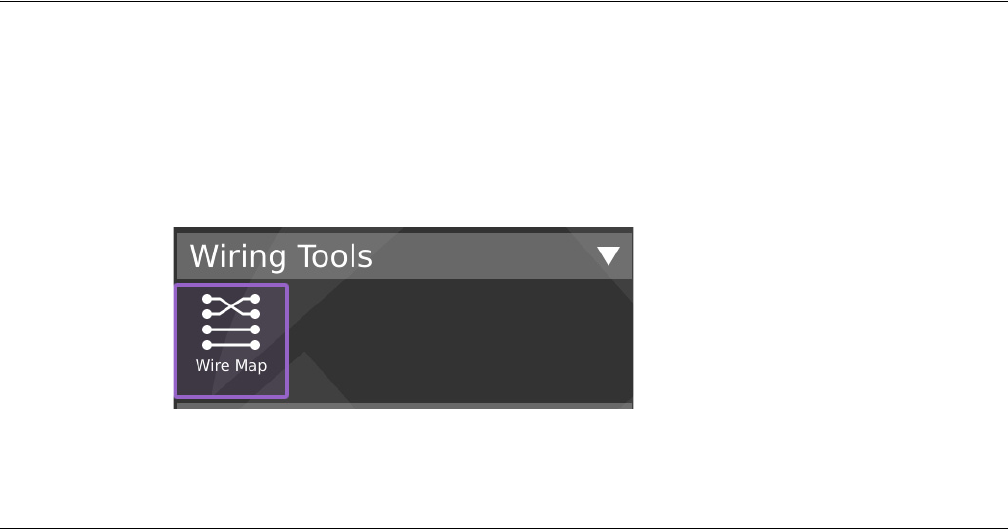
Chapter 5 Wiring Tools
About the Wiring Tools
OneExpert DSL User’s Guide
46 22052280, Revision 001 April 2014
About the Wiring Tools
The purpose of the Wiring Tools tests are to test and map cables/wires, verify that the HPNA links and
devices are installed and fully provisioned, and to verify that the entire HPNA network is operating correctly
To access the wiring tools
1From the main menu, select Wiring Tools.
2Select Wire Map
Wire Mapping
These tests are used to test and map cables/wires. These tests require the use of the smart remote
on the far end of the cable.
There are two wire mapping tests:
• Mapping - calculate cable length based on measured capacitance, using the user-specified
length constant setting. This test also shows the wire mapping between any two pairs in the
cable.
• Toning - mapping the wires by sending a tone across the cable.
Wire Mapping
To map wiring
1Do one of the following:
aIf testing a telephone cable, connect RJ-11 cable to the RJ-11 Wiring connector on the
right panel of the unit.
bIf testing a network cable, connect RJ-45 cable to the RJ-45 Wiring connector on the
right panel of the unit.
2From the Wiring Tools menu, select Wire Map.
The Wiremap - Pin Mapping screen appears. If Trace Toning appears, select the Mapping
system key.
3Either drag the line across the length constant bar or touch the + or - key to adjust the Length
Constant setting.
Chapter 5 Wiring Tools
Wire Mapping
OneExpert DSL User’s Guide
April 2014 22052280, Revision 001 47
Tab le 4 describes some typical constants.
4Press the Start system key to begin the test.
Tab le 5 describes the Wiremap test results.
The test is complete.
Sending tones
The purpose of this test is to send a tone on a network cable. By default, the OneExpert DSL sends
tone on all the wires of a cable.
To trace cables using test tones
1Do one of the following:
aIf testing a telephone cable, connect RJ-11 cable to the RJ-11 Wiring connector on the
right panel of the unit.
bIf testing a network cable, connect RJ-45 cable to the RJ-45 Wiring connector on the
right panel of the unit.
2From the Wiring Tools menu, select Wire Map.
Table 4 Typical data cable length constants
Cable type pF/ft pF/m
Data cable
Cat3
Cat5, Cat5eCat, Cat6
19.0
15.0
62.5
49.0
Coaxial cable
RG58
RG6, RG11, RG59
27.5
16.25
90.0
53.0
Security wire
22AWG, Jacketed
22AWG, Unjacketed
20AWG, Unjacketed
18AWG, Unjacketed
24.0
14.0
16.0
17.0
78.5
46.0
52.5
55.5
Table 5 Wiremap results
Results Description Units Range/
Values
Length Constant This is the current SET length constant used to calculate
cable length based on measured capacitance.
pF/ft
Results This shows the wire mapping between any two pairs in
the cable.
Length Cable length calculated based on Length constant. ft 10.1 - 39.3
Skew Pair skew for each pair. (Cat 5/6 only) ns
Chapter 5 Wiring Tools
Wire Mapping
OneExpert DSL User’s Guide
48 22052280, Revision 001 April 2014
3Select the Toning system key.
The Trace Toning screen appears.
4To start toning the cable, select one of the following:
–High - sends a continuous high tone on all leads of the connected cable.
–Low - sends a continuous low tone on all leads of the connected cable.
–Alternating 1 - sends a high tone follow by a low tone on all leads of the connected
cable.
–Alternating 2 - sends a low tone followed by a short high tone on all leads of the
connected cable.
5After you finish the test, select Off.

OneExpert DSL User’s Guide
April 2014 22052280, Revision 001 49
6
Chapter 6
HPNA Testing
This chapter provides task-based instructions for using the optional HPNA testing features. Topics
discussed in this chapter include the following:
•“About HPNA Testing” on page 50
•“Monitoring the HPNA network” on page 50

Chapter 6 HPNA Testing
About HPNA Testing
OneExpert DSL User’s Guide
50 22052280, Revision 001 April 2014
About HPNA Testing
The capabilities of the OneExpert DSL OneExpert DSL’s optional HPNA testing features include
the following:
Operational mode — This mode monitors the active network during its normal operation and periodically
updates statistics.
Network test mode — This transient mode performs a disruptive network test that transfers a configurable
number of packets across each unidirectional logical link in the network and gathers statistics.
These features are available if the HPNA software option is enabled.
Connecting to the line
After specifying the test settings, you can connect to the line.
To connect to the line
1Connect one end of an Ethernet cable to the Ethernet jack on the right side of the unit.
2Connect the other end of the cable to the Ethernet port of the CPE that is on the HPNA
network (such as a set-top-box or residential gateway).
Monitoring the HPNA network
The following procedure describes how to monitor the HPNA network.
To monitor the HPNA network
1On the Main Menu, select HPNA.
The Station List screen appears. See “Node list” on page 85.
2If desired, use the arrow keys to highlight a specific node and then press the OK key to view
more detailed statistics for that node.
Testing the HPNA network
This test verifies that all installed devices are operating correctly.
To test the HPNA network
1On the Main Menu, select HPNA.
A list of HPNA nodes appears.
Verify that all HPNA devices are present on the network before proceeding.

Chapter 6 HPNA Testing
Testing the HPNA network
OneExpert DSL User’s Guide
April 2014 22052280, Revision 001 51
2Press the * key to specify the HPNA settings.
– Specify the HPNA Minimum Rate (the minimum rate, in Mbps, that will pass)
– Specify the HPNA Minimum SNR (the minimum SNR, in dB, that will pass)
– Specify the Quick Max Packet Lost (the maximum packet loss, in number of packets,
allowed for the Quick Test)
– Specify the Chronic Max Packet Lost (the maximum packet loss, in number of packets,
allowed for the Chronic Test)
3Select the # key to select the type of test to run:
Quick – 5,000 packets. Used to quickly test the HPNA network for common issues.
Chronic – 100,000 or more packets. Used to exhaustively test the HPNA network for chronic
trouble.
4Select the # key to begin the test.
After the network test finishes, the screen updates to report the data rate, modulation, packet
error rate, and signal to noise ratio on the current link.
If the packet error rate is zero and the data rate is over 112Mb, the screen will indicate a pass.
If the packet error rate is non-zero, SNR is less than -34 dB, or the data rate is less than
112Mb, the screen will indicate a failure in red.
5Use the up and down arrow keys to view the results.
6Highlight a specific node and then press the OK key to view node-to-node link information,
such as the MAC addresses and the received power.
7Press the # key to view live statistics between the selected HPNA nodes.
8To save a test report, press the utility (i) key and then select Save Report or Save To Job,
and then specify the report settings such as report name, report format, technician ID, loca-
tion, and other settings as needed.
For more information on the results, see “HPNA results” on page 84.
NOTE:
The size and number of packets may be adjusted from the default settings for each Quick or
Chronic test prior to proceeding.
Chapter 6 HPNA Testing
Testing the HPNA network
OneExpert DSL User’s Guide
52 22052280, Revision 001 April 2014

OneExpert DSL User’s Guide
April 2014 22052280, Revision 001 53
7
Chapter 7
Testing with SmartIDs
This chapter provides task-based instructions for gathering test statistics and verifying connectivity.
Topics discussed in this chapter include the following:
•“About the SmartID tests” on page 54
•“Locating SmartIDs” on page 54
•“Coax Map test” on page 55
•“Whole Home Check” on page 58
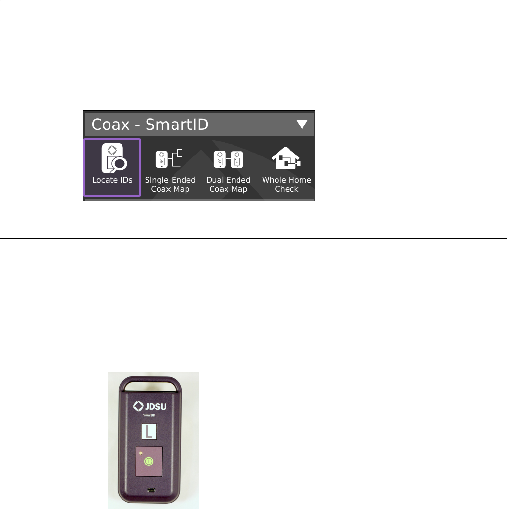
Chapter 7 Testing with SmartIDs
About the SmartID tests
OneExpert DSL User’s Guide
54 22052280, Revision 001 April 2014
About the SmartID tests
The purpose of the SmartID tests are to test and map cables/wires, verify that the HPNA links and
devices are installed and fully provisioned, and to verify that the entire HPNA network is operating correctly
To access the wiring tools
• From the main menu, select Smart ID.
Locating SmartIDs
The purpose of this test is to identify up to 16 the SmartIDs on the network. The SmartIDs will work
through splitters, and multiple SmartIDs can be detected simultaneously.
To locate SmartIDs
1Connect SmartIDs (Figure 10) to the coax at any location in the home where network qualifi-
cation or troubleshooting is desired, such as set top boxes or residential gateways (see
Figure 12 for examples).
2Connect the USB cable from OneExpert DSL to one of the SmartIDs.
3On the SmartID menu, select Locate IDs.
If this is the first test with the Smart IDs, a warning message appears asking you to register
the SmartIDs.
Figure 10 SmartID

Chapter 7 Testing with SmartIDs
Coax Map test
OneExpert DSL User’s Guide
April 2014 22052280, Revision 001 55
This registration applies to the SmartID that the OneExpert DSL is physically connected to.
You will need to repeat the procedure for each SmartID, connecting it directly to the
OneExpert DSL.
aIf the Registration doesn’t automatically come up, select the Actions system key and
then touch SmartID Registration.
bDo one of the following:
– Use the up and down arrows to highlight the label letter for the SmartID and then press
OK.
– Touch the letter for the SmartID
cPlug in the SmartID or enter the serial number (if the SmartID is plugged in, it will adver-
tise its serial number to the OneExpert DSL).
dRepeat step a through step c for each SmartID.
The SmartIDs are registered.
4If the test doesn’t automatically start, press the RESTART system key.
The test runs and then displays the IDs found.
5To enter Fast-Scan mode, press the SCAN system key.
The Locate SmartIDs test performs a single locate function. Fast-Scan mode continuously
scans for connected SmartIDs to allow you to quickly identify multiple coax runs in succes-
sion.
6Use the SAVE system key to save the results to the job file.
Coax Map test
The purpose of this test is to map out the topology of a coax network, from a single point, without
having to perform a two ended test using far end devices. This measurement can be used to locate
devices in a coax cable such as barrels, splitter, and splices.
To run a Coax Map test
1Connect to a SmartID Plus using Bluetooth.
2On the SmartID menu, select Single Ended Coax Map.
The Coax Map screen is displayed.
Select the Mode system key and specify a Map Mode.
– Single Ended Coax Map
– Dual Ended Coax Map
– VDSL Home Run Check
– Whole Home Check (No Diplexer)
– Whole Home Check (Through Diplexer)
Chapter 7 Testing with SmartIDs
Coax Map test
OneExpert DSL User’s Guide
56 22052280, Revision 001 April 2014
Tab le 6 describes the Coax Map results.
Table 6 Coax Map results
Results Description Units Range/Values
Length Total length of the coax leg from test
instrument.
ft. 0-500
dBrl Return loss of the coax leg. dBrl
Comment Description of the event that was
detected in the coax cable
Unknown, Open, Splitter, Barrel/Splice,
Splitter *, and Low Quality Splitter (see
Tab l e 7 for descriptions)
Table 7 Comment result descriptions
Label Description
Unknown This label is used as a last resort when no other signatures can be identified.
Open Indicates an event that has high return loss.
– A home run cable with no passive devices should indicate an open at close to 0 dBrl
– A cable with a 2-way splitter may have two opens at close to -7 dBrl.
– A cable with a 3-way splitter may have two opens at -14 dBrl and one open at -7 dBrl
Splitter Indicates a passive splitter may be present at this length in the cable under test.
Low Quality Splitter Indicates a low quality splitter may be present at this length. Low quality splitters can induce
standing waves and cause poor performance. These low quality splitters can also cause con-
ventional cable ID to function incorrectly since many are DC coupled causing the ID resistive
values to be placed in parallel.
Splitter * Indicates an assumed splitter. The instrument has not detected a splitter signature. However,
based on the data signature the instrument has deduced that a splitter is likely present.
NOTE: If the length to the splitter* and the first open are the same, it is likely a splitter with an
open port.
Barrel/Splice Indicates an event was detected followed by a single low loss open event. This can be caused
by barrel splices, Low Quality Splitter with an open port, severely kinked or crimped cable (Sta-
bles), poor connector, etc….
The return loss of the Barrel/Splice event should be considered when determining what action,
if any, is required. Lower return loss (around -20 dBrl) values may not require action, but high
values indicate an event that may be effecting cable performance.
NOTE:
In the unlikely event that the legs of a splitter are the same length, the instrument will report a
single event with a return loss value that approximately equals the sum of the events.
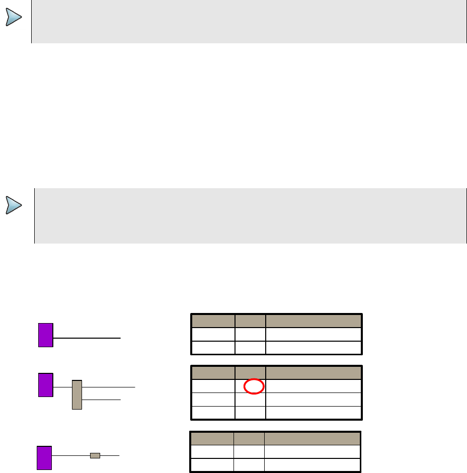
Chapter 7 Testing with SmartIDs
Coax Map test
OneExpert DSL User’s Guide
April 2014 22052280, Revision 001 57
A cable ID is displayed above the system keys. The OneExpert DSL will only find an ID if it's
connected to a single cable with an ID on the other end. The RFIDs, however, will work
through splitters and multiple tags can be detected.
For any given coax cable, the coax map test locates each item and presents the results in an
easy to read table. The table indicates the location of items in terms of a length in feet, from
the test instrument. The table also indicates the return loss at each item in dBrl.
If possible, the OneExpert DSL will also identify items such as opens, splitters, barrels, or
splices based on TDR measurements performed on the cable. In some cases, based on
reflection characteristics, the test set will indicate the presence of bad splitters. If unusual
cable characteristics are measured, the OneExpert DSL will indicate an “unknown” item in the
cable.
If the OneExpert DSL is used to measure a home-run cable, it will indicate an 0 dBrl open,
and the full length of the cable.
Figure 11 shows several cable topologies on the left and the corresponding coax map table
on the right. The dBrl level at each splitter will be relatively low and depend on the quality of
the splitter. Lower return loss indicates a better splitter.
NOTE:
The cable ID won't work properly if there's a cable plugged into the side of the unit (must use
only the coax connector on the top).
TROUBLESHOOTING TIP:
If the results table indicates four or more events, it may indicate a situation where a complex
cable topology is causing multiple reflections. In this case, measurement accuracy can be
improved by performing step by step sectionalization starting with the first item in the table.
Figure 11 Cable topologies and coax map tables
Drop 1
100ft
Mt
10ft 65ft
40ft
Splitter A
Mt
Drop 2
Drop 3
Drop 6
70ft
Mt
Barrel
Open 0 100
Comment dBrl Length (ft)
Open -3 85
Barrel/Splice -20 70
Comment dBrl Length (ft)
Open -7 75
Open -7 50
Splitter -20 10
Comment dBrl Length (ft)
15ft
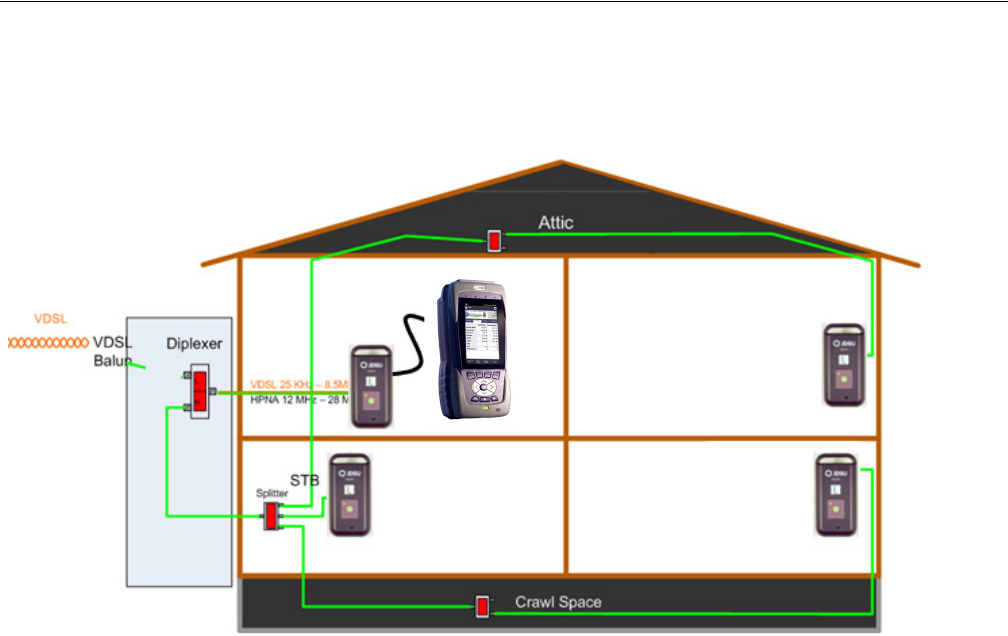
Chapter 7 Testing with SmartIDs
Whole Home Check
OneExpert DSL User’s Guide
58 22052280, Revision 001 April 2014
Whole Home Check
The SmartIDs allow the technician to connect the OneExpert DSL directly to any single SmartID
device which then communicates with any other connected SmartID devices (as shown in
Figure 12) in order to certify an in-home network and provide distances to found impairments.
If a Diplexer is on the network, disconnect the VDSL connection.
The difference in the SmartIDs versus the other terminators is that the terminators only indicate their
location; whereas the SmartIDs each also are used to identify their location, but also each SmartID
does a broadband noise ingress measurement, dual-ended FDR for coax mapping and frequency
sweeping to locate impairments.
There are three test modes
• Locate SmartIDs – finds and identifies all SmartIDs currently connected to the network.
• Home Run Check – a two-point (two SmartIDs) test across the cable connecting at the resi-
dential gateway and the diplexer locations.
• Whole Home Check – tests a complex cable network that may or may not include a Diplexer.
It is intended to qualify the network for HPNA.
Figure 12 SmartID connection
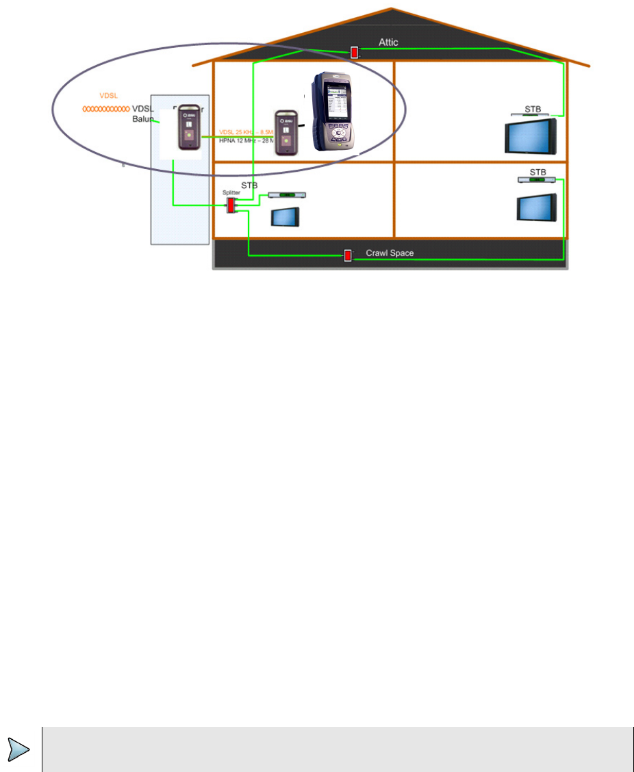
Chapter 7 Testing with SmartIDs
Whole Home Check
OneExpert DSL User’s Guide
April 2014 22052280, Revision 001 59
Testing the home link
The Home Run Check tests the cable connecting the residential gateway to the diplexer (see
Figure 13) or, if there is no diplexer, to the set top box (STB).
To run a Home Run Check
1Connect a SmartID to the coax cable at the residential gateway location.
2Connect the USB cable from OneExpert DSL to the SmartID at the RG.
3Disconnect the cable that runs between the diplexer and the residential gateway, and then
connect a SmartID to the cable (this takes the diplexer out of the test).
4Select the Mode system key and specify a VDSL Home Run.
The SmartID connected to the OneExpert DSL is highlighted. If any impairments were found,
an exclamation point will be shown on the cable, the header will be red, and the background
of one or more SmartIDs may be red. To view information for the cable segment or the other
SmartID, press the left or right arrow keys. The details appear in the box.
5To save the results to a report, use the Tray menu (“Saving a report” on page 32).
Testing the home network
The Whole Home Check maps a coax network and provide distances to found impairments.
To run a Whole Home Check
1Disconnect the cable or DSL feed. If using a diplexer, disconnect the feed to the diplexer (and
leave it open).
Figure 13 Home Run Check
NOTE:
All live network signals must be disconnect from the coax network under test.
Chapter 7 Testing with SmartIDs
Whole Home Check
OneExpert DSL User’s Guide
60 22052280, Revision 001 April 2014
2Connect a SmartID at the point of entry and use the USB cable to connect the
OneExpert DSL to the SmartID.
In order to map the network accurately, make sure that you connect to the primary SmartID
(connected to the OneExpert DSL with a USB cable) on the main side of the residential
gateway or splitter and not on a branch leg.
3Place other SmartIDs at any location in the home wherever network qualification or trouble-
shooting is desired, such as TVs, set top boxes or cable modems.
There are three possible test configurations:
aNID without diplexer: The primary SmartID (connected to the SCH with a USB cable)
should be connected at the RG (in place of the RG), and the remaining SmartID probes
should be connected at the STBs (in place of the STBs).
bNID with diplexer: The primary SmartID (connected to the SCH with a USB cable) should
be connected at the RG (in place of the RG), and the remaining SmartID probes should
be connected at the STBs.
When a Diplexer is on the network, the VDSL connection must be disconnected.
cINID: The primary SmartID (connected to the SCH with a USB cable) should be
connected at the INID coax connection feeding into the home (disconnected from the
INID), and the remaining SmartID probes should be connected at the STBs.
When connecting a SmartID to a wall plate, it is recommended to use a coax jumper
cable of at least 3 feet in length.
Ensure that all devices except SmartIDs are disconnected from the network.
4Select the Mode system key and specify a Whole Home Check.
5On the Select SmartID Test Plan screen, select whether to test through a diplexer (RG -
Through Diplexer) or not (RG - No Diplexer).
– For the NID without diplexer configuration (configuration a, above), select RG - No
Diplexer.
– For the NID with diplexer configuration (configuration b, above), select RG - Through
Diplexer.
– For the INID configuration (configuration c, above), select RG - No Diplexer.
6Begin the test.
During the test, a pop-up message appears if any of the following is detected:
– Near-end connection issue (i.e. open, short, loose connection, poor fitting, poor barrel on
SmartID)
– Far-end connection issue (i.e. poor connection, fitting barrel, etc; partial short)
– SmartID(s) detected but not mapped issue
– SmartID mapping placement questionable (due to processed FDR data producing ambig-
uous length/location data for the particular SmartID probe)
– Excessive noise ingress measured
– Network Map obscured message warning for diplexer, filter, amplifier, etc.
– Test FAILs if there is filter(s) or amplifier(s) present in the network
Note, that the “RG – Through Diplexer” test allows Diplexer in the network
After the test completes, the result test summary appears.
Chapter 7 Testing with SmartIDs
Whole Home Check
OneExpert DSL User’s Guide
April 2014 22052280, Revision 001 61
The test summary displays the paths between SmartIDs and indicates whether the quality of
the path between the two points is passing or failing based on pre-set limits. The upper right
area shows how many SmartIDs were detected and now many were mapped; it will be red if
the numbers don’t match. The left side of the screen will show the frequency sweep and noise
ingress measurement results for each highlighted box, which corresponds to the two points
between SmartIDs in the coax network.
7To save the results to a report, use the Tray menu (“Saving a report” on page 32).
Chapter 7 Testing with SmartIDs
Whole Home Check
OneExpert DSL User’s Guide
62 22052280, Revision 001 April 2014

OneExpert DSL User’s Guide
April 2014 22052280, Revision 001 63
8
Chapter 8
Copper Testing
This chapter provides task-based instructions for using the optional OneExpert DSL copper testing
features. Topics discussed in this chapter include the following:
•“About copper testing” on page 64
•“Measuring voltage” on page 64
•“Locating faults using the TDR” on page 65
•“Measuring opens” on page 66
•“Measuring longitudinal balance” on page 67
•“Detecting load coils” on page 67
•“Running a OneCheck Copper test” on page 69
•“Routing the cables through the glove” on page 69
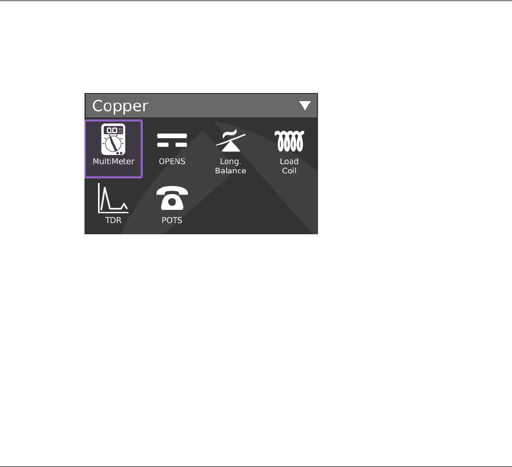
Chapter 8 Copper Testing
About copper testing
OneExpert DSL User’s Guide
64 22052280, Revision 001 April 2014
About copper testing
The OneExpert DSL Tester’s copper features allow quick turn-up and basic troubleshooting of the
copper local loop.
To access the copper tests, touch Copper from the main menu. The drop down menu appears.
You can also perform specific measurements for the following tests:
•Multimeter
– AC volts
– DC volts
– Resistance
•TDR
• Opens (distance) and capacitance
•Balance
• Load coil detect
•POTS
Each of these tests is described in the following sections.
Measuring voltage
The multimeter function allows measuring of AC and DC voltage.
To measure voltage
1Select Connect the Tip (A), Ring (B), and Ground (Earth) leads to the line under test.
2From the Copper menu, touch the Multimeter button.
3Select AC Volts in the lower right.
The AC Voltage menu appears.
Chapter 8 Copper Testing
Locating faults using the TDR
OneExpert DSL User’s Guide
April 2014 22052280, Revision 001 65
4To specify the connection, touch the connection:
– Tip to Ring (A to B)
– Tip to Gnd (A to E)
– Ring to Gnd (Ground) (B to E)
5To specify the termination, select Options, and then select the one of the following:
– 1MEG-ohm Term
– 100K-ohm Term
6To measure DC, select DC Volts in the lower right.
The DC Voltage menu appears.
7To switch between continuous and snapshot mode, use the left system key Snapshot or
Continuous.
8To save the results to a report, use the Tray menu (“Saving a report” on page 32).
9To learn what your results mean, see “AC voltage” and “DC voltage” in Chapter 10 “Test
Results”.
Measuring voltage is complete.
Locating faults using the TDR
The Time Domain Reflectometer (TDR) feature helps locate cable faults. The TDR identifies
bridged taps, wet sections, load coils, shorts, opens, and splices on the span.
The following procedure describes how to locate cable faults using the TDR.
To locate cable faults using the TDR
1Connect the Tip (A), Ring (B), and Ground (Earth) leads to the line under test.
2From the Copper menu, touch the TDR button.
3Press the Start TDR system key.
The TDR graph appears.
4To change the TDR mode, select the Mode system key, and then select SmartGainTDR
(applies 0 gain to 24 AWG cable), In Home TDR (does not include Pulse Width), or Standard
TDR.
5To change the cable type, select the Options system key, and then select Cable Type.
6To add a DC pulse in order to see changes in the graph, select the Options system key, and
then select Stress. The spike or dip will shift when the pulse is applied.
NOTE:
You can also press the up or down arrow key to move among the connections.
NOTE:
The TDR must be running for Stress Mode to be available. It is greyed out when the TDR is
stopped.

Chapter 8 Copper Testing
Measuring opens
OneExpert DSL User’s Guide
66 22052280, Revision 001 April 2014
A warning appears during the stress pulse to indicate higher voltage is present.
7To adjust the Gain or Pulse Width, either drag the line across the bar or touch the + or - key
to adjust it.
Pulse Width only appears when Pulse Width is selected on the Options pop-up menu (from
the Options system key).
8To help identify small or distant faults, use the up or down arrow keys to gain the vertical axis
and enhance the reflection of faults. Do not apply excessive gain. This makes a normal condi-
tion appear as a fault.
9If you want a larger image, you can rotate the screen to Landscape by selecting the Trace
system key and then select Landscape.
10 Using the Peak Hold mode, the OneExpert DSL DSL can display minimum, maximum, and
current TDR traces over a test period. This feature is useful for analyzing faults that occur
intermittently. To enable Peak Hold mode, select the Options system key and then select
Peak Hold.
11 To save the results to a report, use the Tray menu (“Saving a report” on page 32).
12 You can also view and compare current and saved TDR traces using the Results key. For
information on saving your results in graphical form, see “Saving results” on page 78.
13 To learn what your results mean, see “TDR” in Chapter 10 “Test Results”.
Locating cable faults with the TDR is complete.
Measuring opens
The opens feature measures the total electrical (capacitive) length of a pair.
To measure opens
1Connect the Tip (A), Ring (B), and Ground (Earth) leads to the line under test.
2From the Copper menu, touch the Opens button.
3For greatest accuracy, JDSU recommends that you compensate the opens measurement to
remove the effects of the test leads. To compensate the opens measurements
aSwipe downward on the screen to access the Tray menu.
bSelect the OPENS Compensation system key
cFollow the instructions on the screen to connect the black, red, and green leads to
perform test lead compensation.
dTouch Compensate.
The compensation stops automatically when finished.
4Press the Home navigation key to return to the Opens menu.
Chapter 8 Copper Testing
Measuring longitudinal balance
OneExpert DSL User’s Guide
April 2014 22052280, Revision 001 67
Measuring longitudinal balance
Balance is a number representing the quality of the telephone circuit and the degree to which the
Tip (A) and Ring (B) conductors are electrically the same in their ability to cancel noise. The balance
measurement is used to identify poor loop quality or cable bonding and grounding issues that allow
excessive loop noise. Wideband background noise is covered in the WBTIMS section.
To measure longitudinal balance
1Connect the Tip (A), Ring (B), and Ground (Earth) leads to the line under test.
2From the Copper menu, touch the Long. Balance button.
The Longitudinal Balance menu appears.
The test begins automatically.
3To save the results to a report, use the Tray menu (“Saving a report” on page 32).
4To learn what your results mean, see “Longitudinal balance” in Chapter 10 “Test Results”.
Measuring balance is complete.
Detecting load coils
The OneExpert DSL can detect up to five load coils that may exist on the line, out to 27,000 (8,200
meters) feet. It will also report a short, open, or a high noise condition, if detected. For accurate load
coil detection, test on a pair without voltage (supplied by a battery). Although the detector will work
with voltage on a pair, accuracy will be compromised. In addition, the detector works best when the
last coil is followed by 1200 feet (336 meters) of cable.
To detect load coils
1Connect the Tip (A), Ring (B), and Ground (Earth) leads to the line under test.
2From the Copper menu, touch Load Coil.
The Load Coil Detector menu appears.
The count appears in the box. If at least one load coil is detected, the distance to the first load
appears.
If noise, a short, or an open is detected, it appears on this screen.
3To save the results to a report, use the Tray menu (“Saving a report” on page 32).
4To learn what your results mean, see “Load coil” in Chapter 10 “Test Results”.
Detecting load coils is complete.
NOTE:
The distance to first load measurement assumes no other impairments are present between the
OneExpert DSL and the first load coil. If other impairments are present, accuracy is reduced.
If voltage greater than 50V peak is present, the test will abort.

Chapter 8 Copper Testing
Testing voice service and Caller ID
OneExpert DSL User’s Guide
68 22052280, Revision 001 April 2014
Testing voice service and Caller ID
The POTS dialer allows you to place and receive voice calls to verify that the service is working
properly. You can also use the dialer for the following tasks:
– to drop battery for opens testing
– to establish a quiet termination for balance and noise tests
– to determine if loss at 1004 Hz is acceptable
– to test incoming caller ID number and name
The following procedure describes how to test voice service and caller ID.
To test voice service and caller ID
1Connect the Tip (A), Ring (B), and Ground (Earth) leads to the line under test.
2From the Copper menu, touch POTS.
The POTS Dialer menu appears.
3Place a call.
aDial the number using the speed-dial (Speed system key) or manually enter the phone
number using the keypad.
bTo use pulse dialing, press the Actions system key and then select Pulse Dialing.
cPress the OK key to initiate the call.
dSpeak into the microphone located above the OK key.
eOptional. To mute the microphone, press the Actions system key, and then select Mute
(or Un Mute) Microphone.
The mute feature is only available when off hook.
fPress the On Hook system key to end the call.
4Receive a call.
aRequest someone to call you.
bWhen the OneExpert DSL indicates an incoming call, press the Off Hook system key.
cFor lines that have caller ID, the name and number information appears in the box.
dOptional. To mute the microphone, press the Actions system key, and then select Mute
(or Un Mute) Microphone.
eThe mute feature is only available when off hook.
fPress the On Hook system key to end the call.
Testing voice service and caller ID is complete.

Chapter 8 Copper Testing
Running a OneCheck Copper test
OneExpert DSL User’s Guide
April 2014 22052280, Revision 001 69
Running a OneCheck Copper test
The OneCheck Copper test is a JDSU out-of-service pair quality test. It automatically performs a
series of test including: DVOM (AC/DC volts, resistance), Opens/Capacitance, Balance, and Load
Coil Detect. It also compares results to user-defined threshold values and provides a pass/fail indi-
cation.
To run a cable check
1Connect the tip (A), ring (B), and ground (earth) leads to the line under test.
2From the main menu, select OneCheck Copper.
The test begins to run.
As each test runs, the test summary is updated. The summary provides a simple pass/fail
indication.
The test stops automatically when complete.
3To view more detail, use the arrow keys to scroll through the result values.
To learn what your results mean, see Chapter 10 “Test Results”.
4To save the results to a report, use the Tray menu (“Saving a report” on page 32).
Performing a cable check is complete.
Routing the cables through the glove
The glove accessory is designed to hold the copper test leads so you don’t have to disconnect them
from the instrument.
To route the cables through the glove
1Turn the OneExpert DSL over, onto the front panel.
2Unzip the back flap of the glove.
3Push the cables through the opening at the bottom and pull them up to the copper connec-
tors.
4Connect the cable leads to the connectors.
5Pull the cables with the blue and yellow leads to the right side and use the velcro straps to
hold the cables in place, as shown in Figure 14.
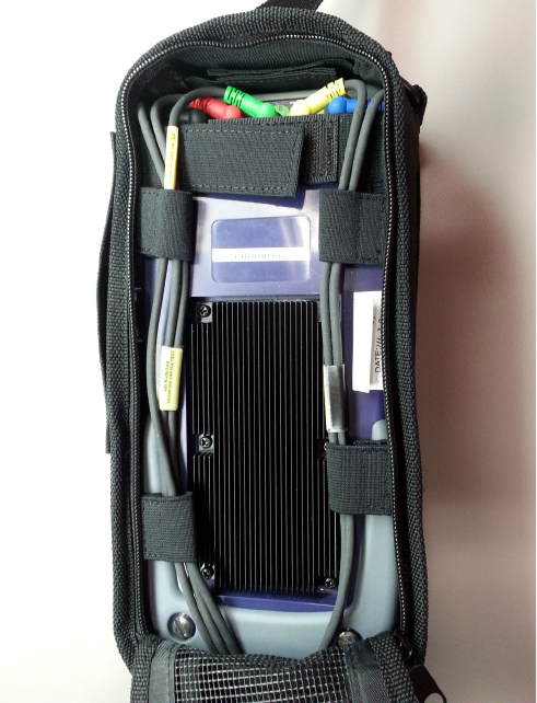
Chapter 8 Copper Testing
Routing the cables through the glove
OneExpert DSL User’s Guide
70 22052280, Revision 001 April 2014
6Pull the cables with the red, black, and green leads to the left side and use the velcro straps
to hold the cables in place, as shown in Figure 14.
Figure 14 Cable routing through the back of the glove
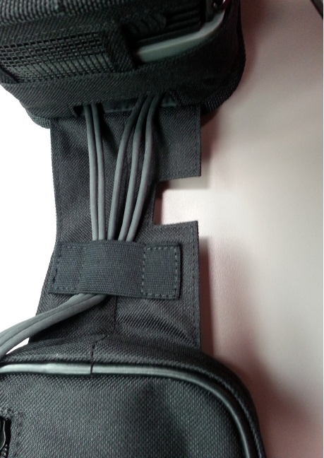
Chapter 8 Copper Testing
Routing the cables through the glove
OneExpert DSL User’s Guide
April 2014 22052280, Revision 001 71
7Use the velcro strap in the glove hinge to hold the cables, as shown in Figure 15.
8Wind the ends of the cable and fit them into the zippered pocket on the inside of the front of
the glove.
9Close the front of the glove and then pull the strap from the back over the top and into the
connector just above the JDSU logo.
Figure 15 Cable routing through the hinge of the glove
Chapter 8 Copper Testing
Routing the cables through the glove
OneExpert DSL User’s Guide
72 22052280, Revision 001 April 2014

OneExpert DSL User’s Guide
April 2014 22052280, Revision 001 73
9
Chapter 9
Using the OneExpert DSL with a mobile device
This chapter provides task-based instructions for using the optional app that is available for mobile
devices. Topics discussed in this chapter include the following:
•“About using the OneExpert DSL with a mobile device” on page 74
•“Controlling the OneExpert DSL user interface” on page 74

Chapter 9 Using the OneExpert DSL with a mobile device
About using the OneExpert DSL with a mobile device
OneExpert DSL User’s Guide
74 22052280, Revision 001 April 2014
About using the OneExpert DSL with a mobile device
Before using the OneExpert DSL with a mobile device, verify the following:
• The mobile device must have the OneExpert app installed (available on the AppStore or from
your JDSU representative).
• In order to use the OneExpert DSL with a mobile device, the OneExpert DSL must be have
the Apple option enabled.
• In order for the OneExpert DSL to communicate with the mobile device, the OneExpert DSL
must have the Bluetooth option enabled.
To verify your options, go to the Options menu in the System Settings.
Controlling the OneExpert DSL user interface
To control the user interface of an OneExpert DSL, the mobile device (iPad or similar) must pair with
the OneExpert DSL over Bluetooth. Then, using the OneExpert DSL app on the mobile device, you
can connect to an OneExpert DSL and control the user interface.
To control the OneExpert DSL with a mobile device
1On the OneExpert DSL, verify that Bluetooth is enabled.
To do this, go to the Bluetooth menu (in the System Settings menu) and verify that the box
next to Enabled has a check mark.
2On the mobile device, do the following:
aGo to the Settings menu, and verify that Bluetooth is On.
bSearch the devices list to find the OneExpert DSL unit that you wish to connect to.
cYou may get a message asking you to confirm the pairing. Touch Ok.
3On the OneExpert DSL, do the following:
aOn the Bluetooth Settings menu, touch Scan for devices.
bFind the mobile device that you wish to connect to, and then select it.
cYou may get a message asking you to confirm the pairing. Touch Ok.
4On the mobile device, launch the OneExpert app.
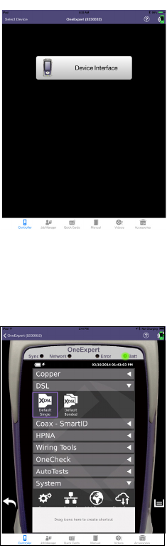
Chapter 9 Using the OneExpert DSL with a mobile device
Controlling the OneExpert DSL user interface
OneExpert DSL User’s Guide
April 2014 22052280, Revision 001 75
The Controller page appears.
5Select Device Interface.
The OneExpert DSL interface appears on the mobile device. You can now control the instru-
ment as if you were pressing the actual buttons on the device. You can run most of the tests
that are available on the OneExpert DSL.
Near the bottom, the Back icon appears on the left and the Tray menu icon appears on the right.
These function as if you pressed the function key on the device.
Across the bottom, icons are available for:
• Controller page – the screen above, allows control of the user interface
• Job Manager – used to
• create, edit, view, and export jobs
• Quick Cards – view quick cards (short documents of instructions)
• Manual – read the manual
•Videos – view instructional videos
• Accessories – view the OneExpert DSL accessories, including how to order
Chapter 9 Using the OneExpert DSL with a mobile device
Controlling the OneExpert DSL user interface
OneExpert DSL User’s Guide
76 22052280, Revision 001 April 2014

OneExpert DSL User’s Guide
April 2014 22052280, Revision 001 77
10
Chapter 10
Test Results
This chapter describes the test results that are gathered when running a test. To view the different
categories of statistics, use either the left and right arrows, or press the number for the desired result
category. Topics in this chapter include the following:
•“Saving results” on page 78
•“DSL Results” on page 79
•“IP Data results” on page 84
•“HPNA results” on page 84
•“SmartID results” on page 86
•“Copper results” on page 87

Chapter 10 Test Results
Saving results
OneExpert DSL User’s Guide
78 22052280, Revision 001 April 2014
Saving results
After running tests, there are two ways to save results:
as a report - used to save the file as text, HTML, or PDF and then export for viewing or printing
using a PC.
to a job - used to associate test results from different applications to a single job
Saving results to a file
After running tests, you can save the results to a report file, and then export for viewing or printing.
To save results to a file
1After your test is finished, use the Tray menu (swipe the screen from top to bottom) and then
select Save Report.
2Specify the report settings.
3Touch Save to save the file to internal storage.
The test results are stored.
Use the File Browser to copy the file to USB for viewing or printing using a PC.
Saving results to a job
If you have an open/active job, you can save the results to a job.
To save results to a job
1After running a test, press the Utility key, and then select Save to Job.
2After your test is finished, use the Tray menu (swipe the screen from top to bottom) and then
select Save to Job.
3Verify the circuit ID and other job information. If the job information is not the desired job,
return to the Job Manager screen and activate the desired job.
4Touch Save to save the results to the job.
The OneExpert DSL returns to the last viewed result screen.
Setting Description
Name Specify a file name for the report. The default file name uses the type of test fol-
lowed by a three digit number that increments with each file save (for example,
cablecheck001 or DSL002).
Format Specify the file format for the report: Text, HTML, PDF.
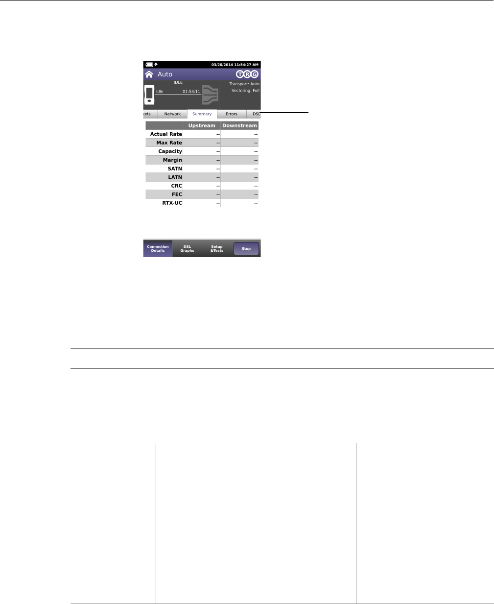
Chapter 10 Test Results
DSL Results
OneExpert DSL User’s Guide
April 2014 22052280, Revision 001 79
DSL Results
The following section describes the results available in DSL mode. Different result categories are
available on different tabs on the screen. To view the different statistics, tap the tab on the screen.
Summary
This category provides a summary of the most frequently used DSL test results. Table 8 describes
the DSL Summary results.
Table 8 DSL Summary results
Result Description Range
Training State The state of modem synchronization (appears
in the menu heading)
Booting, Idle, Init, Showtime
Trained Mode The DSL line format agreed upon during train-
ing (appears in the menu heading).
T1.413, READSL, ADSL2+,
ADSL2, G.Lite, G.DMT, VDSL2
Connection Statistics
Actual Rate Current upstream and downstream connection
rates
32 kB–3.3 MB1 (Up)
32 kB–25 MB1 (Dn)
64 kB–50 MB (Up)2
64 kB–100 MB (Dn)2
Max Rate Maximum upstream and downstream connec-
tion rates
32 kB–3.3 MB1 (Up)
32 kB–25 MB1 (Dn)
64 kB–50 MB (Up)2
64 kB–150 MB (Dn)2
Capacity The percentage of total bandwidth currently
used by the actual connect rate upstream and
downstream.
0–100%
Margin SNR margin upstream and downstream 0–63.5 dB
Result category tabs

Chapter 10 Test Results
DSL Results
OneExpert DSL User’s Guide
80 22052280, Revision 001 April 2014
In the saved test report, two additional statistics are included:
•Start Time is the time (time of day) when the DSL modem achieves Showtime. The Start time
is updated if you clear errors.
•Stop Time is the time (time of day) when the report is generated or DSL sync is lost.
DSL statistics
For bonded mode, the same results are shown, but the bonded results are separated into different
screens:
• Group - results for both pairs combined
• Pair 1 or Pair 2 - Same results as the non- screen, except the title.
Packet Statistics
Tab le 9 describes the LAN Statistics.
ATN The degradation of signal strength in dB
upstream and downstream. It is the differ-ence
in Tx power from the transmitter to receiver.
0–126.95 dB (VDLS2)
0–254.9 dB (ADLS2)
Sync Time The elapsed time (duration) since reaching
Showtime.
n/a
1. These are ADSL2 rates.
2. These are VDSL2 rates.
Table 9 LAN Statistics
Result Definition
Link Status Status of the connection.
RX Bytes Total bytes received
RX Frames Total frames received
RX Errors Total errors received
RX Dropped Total dropped frames received
TX Bytes Total bytes transmitted
TX Frames Total frames transmitted
TX Errors Total errors transmitted
TX Dropped Total dropped frames transmitted
TX Collisions Ethernet frames are transmitted “space-available” when there is a break on the sig-
nal on the cable; sometimes frames are transmitted at the same time as another
transmitter, causing a “collision” of frames.
Table 8 DSL Summary results (Continued)
Result Description Range

Chapter 10 Test Results
DSL Results
OneExpert DSL User’s Guide
April 2014 22052280, Revision 001 81
Network Status
Tab le 1 0 describes the Network Status results.
Errors
Tab le 11 describes the DSL Errors.
Table 10 Network Status results
Result Description
Network Status Status of the connection. If testing in Router mode, there are separate status
indications for WAN and LAN.
LAN x If using Multi-VLAN, reports the status of up to three LAN connections.
IP Address The OneExpert DSL OneExpert DSL's IP address to the access the provider net-
work. (IPv4)
Global If using IPv6oE, this is the OneExpert DSL OneExpert DSL's IP address to the
access the global network, beyond the router.
Local If using IPv6oE, this is the OneExpert DSL OneExpert DSL's IP address to the
access the local network.
Subnet prefix If using IPv6oE, this is the length of the subnet prefix.
Netmask The OneExpert DSL OneExpert DSL’s netmask address. IP devices use a netmask
IP address to determine if IP packets are to be routed to other networks or sub-net-
works. (IPv4)
Gateway The OneExpert DSL OneExpert DSL's gateway address. When an IP device has
determined that a packet is not addressed to it or devices on the same sub-network
(subnet), it sends all such packets to the gateway address for further routing to the
correct address.
DNS Domain Name Services. When using internet addresses such as www.jdsu.com,
the OneExpert DSL OneExpert DSL (and all IP devices) must translate to an IP
address (such as 157.234.12.20) in order to route the packets or data. To do so, it
first requests a DNS server to translate an internet address into an IP address; then
the OneExpert DSL OneExpert DSL can correctly route IP pings or other data. The
DNS address must be that of a real DNS server, preferably in the provider network.
MAC Address The MAC address of the LAN.
Table 11 DSL Errors
Result Description
FEC Forward Error Correction upstream and downstream for Fast Path and Interleave
Path.
CRC Cyclical redundancy check upstream and downstream for Fast Path and Interleave
Path.
ES Errored Seconds. Number of seconds during which a LOS, SEF, LPR, or CRC
occurred since starting the test.
SES Severely Errored Seconds. Number of seconds during which one or more LOS, SEF,
or LPR errors were present, or 18 CRCs occurred.

Chapter 10 Test Results
DSL Results
OneExpert DSL User’s Guide
82 22052280, Revision 001 April 2014
DSL RTX
Tab le 1 2 describes the RTX (DSL Retransmission) results.
Signal
This category provides statistics for the signal. Tab le 1 2 describes the DSL Summary results.
UAS Unavailable Seconds. A count of the number of test seconds which met the ITU-T
Rec. G.821 definition of unavailable time.
LOS Loss of Signal. Number of errored seconds due to loss of signal.
LOF Loss of Frame. Number of errored seconds due to loss of framing.
LOM Loss of Margin Errors. Number of errored seconds due to loss of margin.
Table 12 DSL RTX results
Result Description
Status The state of modem synchronization
RTX-TX The number of retransmitted DTUs that were received.
RTX-C The number of DTUs we received a correction for
RTX-UC The number of DTUs that did not get a retransmission in time.
INP Rein The effective INP that G.INP support is giving us.
Table 13 DSL Signal results
Result Description
Sync Count The number of synchronization attempts. it is possible that modems do not
synchronize immediately and make multiple attempts before achieving syn-
chronization.
Uptime Amount of time the modems have been synchronized.
Path RJ45, (T/R or A/B)
SATN Signal attenuation. Attenuation average of the bins/tones that contain the
actual signal (empty bins are not included).
LATN Line attenuation. Attenuation average of all tones/bins (the entire line, includ-
ing empty bins/tones).
Tx Power Power level, in dB, of the VDSL signal, downstream (from the DSLAM) and
upstream (transmitted by the OneExpert DSL OneExpert DSL).
INTLV Delay Interleaving depth set by the DSLAM. This is a measure of latency introduced
on the link due to the scrambling of DSL frames to protect data and create a
more reliable link.
Actual INP The INP (Impulse Noise Protection) values negotiated during training.
Table 11 DSL Errors (Continued)
Result Description

Chapter 10 Test Results
DSL Results
OneExpert DSL User’s Guide
April 2014 22052280, Revision 001 83
DSL Identity
Tab le 1 4 describes the DSL Identity results.
DSL Graphs
The graphs provide a graphical representation of the following:
• SNR (signal to noise ratio) Per Tone
• Bits Per Tone (BPT)
• QLN (quiet line noise) Per Tone
• Hlog Per Tone
Troubleshooting using the graphs
The SNR graph indicates line quality. The BPT graph indicates the total bit rate and is a useful tool
for finding disturbers. Bits per tone is defined as bits assigned per DMT tone.
Examine the portions of the graphs where there are dips or breaks. These dips represent areas
where interference is degrading the DSL signal.
Tab le 1 5 lists common noise sources and the corresponding frequencies and tones.
Table 14 DSL Identity results
Result Description
HW Type Type of modem hardware
HW Rev Revision of the hardware
xTU-R SW Revision SW revision of the local modem
xTU-R PHY Revision PHY firmware revision for the local modem
xTU-O Vendor CO vendor code
xTU-O Rev CO revision number
Table 15 Noise sources and tones
Noise Source Noise Frequency (kHz) Tone # Tone Frequency (kHz)
ISDN BRI 40 9 38.8125
HDSL passband center 196 45 194.0625
HDSL passband max 392 91 392.4375
HDSL2 274 64 276
T1 passband center 772 179 772
E1 passband center 1024 237 1022

Chapter 10 Test Results
IP Data results
OneExpert DSL User’s Guide
84 22052280, Revision 001 April 2014
IP Data results
The following section describes the results available in IP Data mode. To view the different catego-
ries of statistics, use either the left and right arrows, or press the number for the desired result cate-
gory.
Ping results
Tab le 1 6 describes the ping results.
File Transfer results
Tab le 1 7 describes the File Transfer results.
HPNA results
The following section describes the results available in HPNA mode.
Table 16 IP Ping results
Result Definition
Destination Destination address where the ping is being sent.
Message Status message.
Echos TX The number of ping messages sent.
Replies RX The number of echo reply messages returned to the OneExpert DSL from the des-
tination.
Replies Lost The number of pings that did not return to the OneExpert DSL. This could be
caused by an unresponsive target (destination) or by heavy congestion on the net-
work; the more packets lost the more congested the network, indicating slow or
poor throughput.
Replies Lost % The percentage of lost echos compared to echos sent.
Echos RX The number of ping messages sent to the OneExpert DSL from other devices on
the network.
Ping Time The current, minimum, maximum, and average time in milliseconds it has taken
one transmitted ping to reach its destination and receive a reply back to the
OneExpert DSL.
Table 17 File Transfer results
Result Description
Status The status of the transfer.
Bytes Transferred The number of bytes transferred.
Transfer Rate The speed that the file was uploaded or downloaded.
Chapter 10 Test Results
HPNA results
OneExpert DSL User’s Guide
April 2014 22052280, Revision 001 85
Node list
Tab le 1 7 describes the Node List results.
Node details
Node details provides details for a particular node.
Network Test
Tab le 1 9 describes the HPNA results.
Table 18 Node List results
Results Description Units Range/Values
H This column indicates the host/client of every HPNA
device in the network
H: Host device
Id The station identifier for the HPNA device. numeric digit 0-9
Hpna MAC The MAC address of the HPNA device in the network aa:bb:cc:dd:ee:ff Each field is 00-FF hex
Ver – Chip The device’s firmware version and CopperGate™ chip ID. revision-chip id Chip ID = Chipset
0 3010
1 3110
2 3210
3 3310
4 3320
Table 19 HPNA results
Results Description Units Range/Values
Station ID -> ID This is a directional indication of each link denoted by
each node ID
Rate, Mod Mbps This is the current data rate, and baud/constellation of the
specific link.
Mbps, MBaud/bits
per symbol
0-112, 2-24/2-10
PER The Packet Error Rate on the specific link. Rate x.xxe+yy 0.00e0 - 1.00e0
SNR This is the Signal to Noise Ratio of the specific link. dB
Receive and Transmit Results
bytes The number of total (good and bad) transmitted or
received bytes
Bytes
packets The number of total (good and bad) transmitted or
received packets.
Packets
bcast The number of transmitted or received broadcast packets. Packets
mcast The number of transmitted or received multicast packets. Packets
dropped The number of transmitted or received packets dropped
due to lack of resources.
Packets
Chapter 10 Test Results
SmartID results
OneExpert DSL User’s Guide
86 22052280, Revision 001 April 2014
SmartID results
The following section paragraphs describes the results available in SmartID tests.
Test Summary
This category provides an overview of the results, including basic pass/fail indications of the links
between the SmartIDs. Use the arrow keys to navigate and highlight a section. The details for that
section appear. If you navigate to a section/link that failed, the results on the left update and you
can see which measurement failed.
Detailed View
This category shows detail of the selected section/link of the network between two SmartIDs. Use
the # key to reverse the direction (change the focus from the near end of the cable to the far end).
Network Map
This category shows the layout of the network. The SmartID connected to the OneExpert DSL is on
the left and the home network cascades to the right. Use the up and down arrow keys to select
different SmartIDs on the map. Press OK to see details of a particular segment.
Sweep Data
This category shows a graph of the frequency sweep. Use the # key to reverse the direction.
crc The number of received packets that have had an invalid
checksum.
(NOTE: There is no count for transmitted packets)
Packets
Protocol Messages
ctrl_log_req The number of control requests from the local host (CERT
protocol.)
ctrl_log_rec The number of control replies to the local host (CERT pro-
tocol.)
ctrl_rem_req The number of control requests from a remote host
(CERT protocol.)
ctrl_rem_rec The number of control replies to a remote host (CERT
protocol.)
Table 19 HPNA results (Continued)
Results Description Units Range/Values
Chapter 10 Test Results
Copper results
OneExpert DSL User’s Guide
April 2014 22052280, Revision 001 87
Copper results
The copper results are described in the tables below.
AC voltage
You measure AC volts to:
• detect the presence of hazardous voltage.
• measure stray or foreign voltages.
• measure ringer voltage level.
AC voltage results on Tip (A) to Ring (B) should be 0.0 volts. Tip (A) to ground and Ring (B) to
ground should be equal to each other. Anything else indicates AC signal interference and/or an
unbalanced line.
Tab le 2 0 describes the AC voltage result.
DC voltage
You measure DC volts to:
• detect and measure CO/exchange battery voltage.
• detect crossed battery conditions.
To measure DC volts, remove the line battery and measure Tip (A) and Ring (B) to ground. It should
be < 3.0 volts; anything else indicates crossed battery that inhibits digital signals.
Tab le 2 1 describes the DC voltage result.
Table 20 AC Voltage result specifications
Range (VAC) Resolution (V) Accuracy
AC peak + [VDC] < 300 1 2% ± 1.0V
WARNING: INSTRUMENT DAMAGE
Although the OneExpert DSL OneExpert DSL is designed to measure hazardous voltage, it is
designed to do so on telecom circuits, not power mains. Hazardous voltages may be on the
power lines. 220 mains (RMS) are equivalent to 308 peak. Connecting to these circuits may
result in damage to equipment or serious injury.
Table 21 DC voltage result specifications
Range (VDC) Resolution (V) Accuracy
AC peak + [VDC] < 300 1 2% ± 1.0V

Chapter 10 Test Results
Copper results
OneExpert DSL User’s Guide
88 22052280, Revision 001 April 2014
Resistance
You measure resistance to test line continuity and quality, and to detect corrosion, shorts, opens,
and faults.
The OneExpert DSL is able to measure resistance in the presence of noise and foreign voltage, but
the accuracy may be reduced, depending on the noise level.
Resistance should be measured with the line disconnected, so that the battery voltage and CO/
Exchange termination don't affect the measurement.
Normal resistance should be at least 5 M; lower values indicate the presence of faults.
Tab le 2 2 describes the resistance result.
Distance to short
This result measure the distance to the short. A resistance measurement of 4 k or less typically
indicates a short. For values greater than 4 k, this function is disabled.
Tab le 2 3 describes the distance to short result.
Leakage
Leakage is a resistance measurement using higher voltage.
Tab le 2 4 describes the leakage result.
Table 22 Resistance result specifications (no ambient)
Range () Resolution ()Accuracy
0 to 999 1 2% ± 2.5
1.0K to 9.99K 10 2%
10.0K to 99.9K 100 2%
100.0K to 999K 1K 2%
1.0M to 9.9M 10K 6.5%
10.0M to 100M 100K 10%
Table 23 Distance to short result specifications
Range (feet) Resolution Range (meters) Resolution
0 to 3000 30 feet 0 to 999 9 meters
3000 to 30,000 100 feet 1000 to 10,000 30.5 meters
Table 24 Leakage result specifications (no ambient)
Range () Resolution ()Accuracy
0 to 49.99 1 2% ± 2.5

Chapter 10 Test Results
Copper results
OneExpert DSL User’s Guide
April 2014 22052280, Revision 001 89
Opens/Capacitance
You measure opens/capacitance to:
• measure total electrical loop length (includes length of bridged taps).
• find wet sections, bridged taps or open faults.
Opens/Capacitance: < 3% difference between Tip (A) and Ring (B) values indicate an acceptably
balanced loop. Anything greater indicates an unbalanced line or open fault, which inhibit digital
signals.
Tab le 2 5 describes the opens/capacitance result.
DC current
You measure DC current to verify if enough current is present to operate equipment including the
phone or caller ID boxes.
DC current on Tip (A) to Ring (B) should be 23 mA at the NID. Anything less will not allow for differ-
ences in temperature and phone equipment will not operate during extremes.
Tab le 2 6 describes the DC current result.
50 to 999 1 5% ± 2.5
1.0K to 9.99K 10 5%
10.0K to 99.9K 100 5%
100.0K to 999K 1K 5%
1.0M to 9.9M 10K 10%
10.0M to 100M 100K 15%
Table 24 Leakage result specifications (no ambient) (Continued)
Range () Resolution ()Accuracy
Table 25 Opens/Capacitance result specifications (no ambient)
Range (feet) Resolution
(feet) Range (meters) Resolution
(meters)
Range
(capacitance)
Accuracy (applies to
capacitance only)
0 to 2,999 1 foot 0 to 999 0.1 meter 0 to 47.1 nF 1% ± 15 pF
3000 to 66000 1 foot 1,000 to 20,000 0.1 meter 47.1 nF to 1.57 µF 2%
Table 26 DC current result specifications
Range Resolution Accuracy
0 to 110 ma 1ma 2% ± 1ma

Chapter 10 Test Results
Copper results
OneExpert DSL User’s Guide
90 22052280, Revision 001 April 2014
Longitudinal balance
You measure longitudinal balance to:
• measure the quality of the pair: a measurement of the degree to which the Tip (A) lead is
electrically the same as the Ring (B) lead.
The more each lead is electrically identical (capacitance, inductance, impedance), the better the
pair will resist induced noise.
The balance result should be >60 dB. Anything less indicates electrical differences between Tip (A)
and Ring (B) that can lead to noise and other signal problems.
Tab le 2 7 describes the DC current result.
Load coil
You check for load coils to ensure there are no load coils present on a digital line (such as ADSL or
ISDN). Load coil detection and elimination is essential in the installation of an xDSL circuit
Tab le 2 6 describes the load coil result.
TDR
A TDR (Time Domain Reflectometer) is used to identify and locate buried splices, shorts and low
resistance faults, opens, bridge taps, load coils, and wet cables.
Velocity of Propagation (VoP) is the speed of the TDR signal travelling down the wire pair relative
to the speed of light. The OneExpert DSL uses this value to convert reflections to distance. To
ensure an accurate distance calculation at the cursor, the VoP should match the cable gage and fill.
The default value is appropriate for 24–26 AWG (4–5 mm) telco aerial cable and provides sufficient
accuracy in most situations.
Tab le 2 6 describes the TDR result.
Table 27 Balance result specifications
Range Resolution Accuracy
28 to 70 dB 1 dB ± 2 dB
70 to 120 dB 1 dB indication only
Table 28 Load coil result specifications
Range Resolution Accuracy
Up to 27,000 ft (8229.6 m) up to 5 ± 1
Table 29 TDR specifications
Range Accuracy
0 to 40,000 ft (12000 m) ± 0.5% of distance

OneExpert DSL User’s Guide
April 2014 22052280, Revision 001 91
A
Appendix A Troubleshooting
This chapter describes how to identify and correct problems related to the OneExpert DSL. Topics
discussed in this chapter include the following:
•“Getting Technical Assistance” on page 92
•“Additional information” on page 92
•“Resolving problems” on page 93

Appendix A Troubleshooting
Getting Technical Assistance
OneExpert DSL User’s Guide
92 22052280, Revision 001 April 2014
Getting Technical Assistance
If you need assistance or have questions related to the use of this product, use the information in
Tab le 3 0 to contact JDSU’s Technical Assistance Center (TAC) for customer support. For the latest
TAC contact information, go to www.jdsu.com or contact your local sales office for assistance. The
regional sales office phone numbers are listed on the back of this manual.
During off-hours, you can request assistance by doing one of the following: leave a voice message
at the TAC for your region; email the North American TAC (tac@jdsu.com); submit your question
using our online Technical Assistance request form at www.jdsu.com.
Additional information
For additional information, visit the OneExpert DSL section of the following web page:
http://www.jdsu.com/en-us/Test-and-Measurement/Pages/default.aspx
Table 30 Technical assistance centers
Region Phone Number
Americas 1-855-ASK-JDSU
301-353-1560
tac@jdsu.com
Cable TV/Multimedia Products 1-800-428-4424 Ext. 8350
(America)
1-317-788-9351 Ext. 8350
(World Wide)
catv.support@jdsu.com
Europe, Africa, and Mid-East +49 (0) 7121-86-1345
(JDSU Germany)
hotline.europe@jdsu.com
Asia and the Pacific +852-2892-0990
(Hong Kong)
+8610-6833-7477
(Beijing-China)

Appendix A Troubleshooting
Resolving problems
OneExpert DSL User’s Guide
April 2014 22052280, Revision 001 93
Resolving problems
If you are having trouble with the OneExpert DSL OneExpert DSL, the following sections describe
common problems and solutions. You should verify whether your problem is listed here before
contacting technical assistance.
The following section addresses questions that may be asked about completing tests with the
OneExpert DSL OneExpert DSL. There are four sections included:
• General
• Copper tests
• Coax tests
• DSL tests
• Data tests
General testing
The following section addresses questions about testing in general using OneExpert DSL.
Issue
Inconsistent test results.
Resolution
Verify that your test leads are good and are connected properly for the test you are performing.
Copper testing
The following section addresses questions about Copper testing.
Issue
The Tip-Ring voltage is reading negative.
Resolution
The Tip and Ring test leads may be swapped. Check your test leads to verify that they are hooked
up properly.
Issue
I am performing an Opens test. The mutual value looks good, but the Tip and Ring values are really
short.
Resolution
Verify the ground. The module must be grounded to the same ground as the pair under test. the
ground. The module must be grounded to the same ground as the pair under test.
Appendix A Troubleshooting
Resolving problems
OneExpert DSL User’s Guide
94 22052280, Revision 001 April 2014
DSL testing
The following section addresses questions about DSL testing.
Issue
The modem cannot achieve sync with the CO.
Resolution
Inability to sync can have many causes. Perform the following steps to troubleshoot:
• Disconnect the customer's DSL modem.
• Verify tester connection to the correct pair.
• Verify the Data mode.
• Verify that the Standard is correct (ADSL2+, G.DMT, Auto, etc.).
• Isolate premise wiring.
• Check for premise alarm system.
• Verify the copper pair is provisioned for ADSL at the CO.
• Test at the CO/Exchange on the customer pair.
• Check the DSLAM modem vendor and software version.
Issue
The modem achieves sync with the CO, but the rate is lower than expected.
Resolution
Verify that you are on an ADSL2, ADSL2+, or VDSL line, as appropriate.
Check the DSLAM configuration - the max rate may be limited there.
Check for premise alarm system on the same pair.
Avoid excessive loop length or high attenuation.
Make sure that you are connected on pins 3 and 4.
Verify the noise margin.
Check the attenuation.
Make sure that you are connected on pins 3 and 4 instead of 2 and 5.
Data testing
The following section addresses questions about Data testing.
Issue
The IP ping menu says pings are being sent, but the network statistics are not incrementing.
Appendix A Troubleshooting
Resolving problems
OneExpert DSL User’s Guide
April 2014 22052280, Revision 001 95
Resolution
Verify the IP address and netmask.
Make sure you are not behind a firewall; they can block ping responses from reaching the host.
The IP ping function only attempts to send a ping every second. Depending on certain conditions,
a physical ping packet may not be sent.
If IPoE standards require that the device has to ARP the address first. If this fails eventually you will
see a ARP HOST UNREACHABLE message. Check to see that the destination IP address and
your configured IP parameters are correct.
Make sure that the Ethernet interface cabling is correct. If the Ethernet cable is not hooked up, or
is hooked up incorrectly, a packet will not be sent. Thus the Ethernet statistics will not increment.
Appendix A Troubleshooting
Resolving problems
OneExpert DSL User’s Guide
96 22052280, Revision 001 April 2014

OneExpert DSL User’s Guide
April 2014 22052280, Revision 001 97
B
Appendix B Specifications
This appendix contains specifications for the OneExpert DSL DSL. Topics discussed in this
appendix include the following:
•“Physical specifications” on page 98
•“Physical specifications” on page 98
•“Environmental specifications” on page 98
•“Power specifications” on page 99
•“Customer Service and Support” on page 99

Appendix B Specifications
Physical specifications
OneExpert DSL User’s Guide 22052280, Revision 001
98 22052280, Revision 001 April 2014
Physical specifications
Tab le 3 1 provides the physical specifications for the OneExpert DSL.
Connector specifications
Tab le 3 2 provides the connector specifications.
Environmental specifications
Tab le 3 3 provides the environmental specifications.
Table 31 Physical specifications
Parameter Specification
Height 9.8" (250 mm)
Width 4.68" (119 mm)
Depth 3.2" (82.4 mm
Weight 4.05 lb. (1.84 kg)
Table 32 Connector specifications
Connector Specification
USB USB 2.0
AC Adapter see “Power specifications”
T/A R/B Ground mini-banana
POTS 8-pin modular (RJ-45)
Ethernet 8-pin modular (RJ-45)
Wiring 6-pin modular (RJ-11) and 8-pin modular (RJ-45)
2&4-Wire VDSL/ADSL 8-pin modular (RJ-45)
Table 33 Environmental specifications
Parameter Specification
Operating Temperature -5 to +50 C (23 to +122F)
Storage Temperature -30 to +60 C (-22 to 140 F)
Humidity 10% to 80% RHNC
Maximum operating altitude 4000 meters (13,123 feet)
Vibration sinusoidal vibration testing per IEC 60068-2-6 (Sinusoidal Vibration)
Shock shock testing to IEC 60068-2-29 Ed. 2.0 “Continuous Bumps.”

Appendix B Specifications
Power specifications
22052280, Revision 001 OneExpert DSL User’s Guide
April 2014 22052280, Revision 001 99
Power specifications
Although battery life varies depending on the type of test, Table 34 provides specifications for the
battery life and the specifications for the AC adapter.
Customer Service and Support
JDSU offers an unmatched and comprehensive portfolio of standard support services, add-on
services, and training options to help customers successfully use purchased JDSU products.
Services that come standard with every product sale include business hour technical assistance,
in-warranty repair, calibration services, upgrade services, and immediate return authorizations.
Add-on services designed to optimize product capabilities and maximize efficiencies include field
engineering and deployment, technical training, 24x7 product support, consulting, and custom soft-
ware development. Refer to the sections that follow for additional details.
Standard support services
Standard support services that accompany the sale of every JDSU product include:
• Instrument repair and calibration services
• Business hour technical assistance
• Access to general warranty information on the JDSU Web site
• Extensive product documentation and related technical information, accessible on the JDSU
Web site
Instrument repair and calibration services
Our service centers provide repair and calibration services for JDSU equipment. JDSU understands
the impact of equipment down time on operations and is staffed to ensure a quick turnaround. Avail-
able services include the following:
Product Repair — All equipment returned for service is tested to the same rigorous standards as
newly manufactured equipment. This ensures products meet all published specifications, including
any applicable product updates.
Table 34 Power specifications
Parameter Specification
Operating time Approximately 20 on/off cycles and tests on a full charge, depending on
usage and conditions.
Charging time 5 hours for a fast charge; for a full charge, allow to trickle charge overnight
Power supply input 100-240VAC, 1.5A, 50-60 Hz
Power supply output 12VDC, 5.0A Max
Power supply operating
temperature range
0 to +40 C (-22 to 104 F)
Appendix B Specifications
Customer Service and Support
OneExpert DSL User’s Guide 22052280, Revision 001
100 22052280, Revision 001 April 2014
Calibration — JDSU’s calibration methods are ISO approved and based on national standards.
For more information, including instructions for returning equipment for repair and/or calibration, go
to: www.jdsu.com/en-us/Test-and-Measurement/support/repair-and-calibration/Pages/
default.aspx.
Technical assistance (business hours)
Expert business hour technical support is provided with your product. For assistance related to the
use of your product, call or e-mail JDSU’s Technical Assistance Center (TAC) in your region. For a
current listing of TAC phone numbers and e-mail addresses, go to: http://www.jdsu.com/en-us/Test-
and-Measurement/services/products-and-systems-support/Pages/default.aspx.
For information about optional 24x7 technical assistance, see “Extended product and systems
support services” on page 100.
Warranty information
Information about standard warranties, terms, and conditions specific to JDSU’s Test & Measure-
ment products is posted on the JDSU Web site. For more information, go to: http://www.jdsu.com/
about-jdsu/pages/jdsu-standard-terms-and-conditions.aspx?rcode=terms.
Product documentation library
An extensive library that includes documentation for JDSU products and related technology-specific
documents is available on the JDSU Web site. For more information, go to: www.jdsu.com/en-us/
Test-and-Measurement/support/Technical-Library/Pages/TechLibrary.aspx.
Add-on services
JDSU offers a broad portfolio of add-on services to enable customers to aggressively build their
competitive advantage within the markets they serve.
Available services include:
• Extended product and systems support, including:
– Optional extended product warranties
– Optional extended repair services
– Calibration management services
– Around-the-clock technical assistance
– A certified pre-owned equipment program
– Tailored support services for your JDSU system
• Various professional and consulting services
• Specialized managed services.
Extended product and systems support services
For information about optional extended product warranties, go to: www.jdsu.com/en-us/Test-and-
Measurement/services/a-z-service-list/Pages/ext-warr.aspx.
Appendix B Specifications
Customer Service and Support
22052280, Revision 001 OneExpert DSL User’s Guide
April 2014 22052280, Revision 001 101
For information about optional extended equipment repair services, go to: www.jdsu.com/en-us/
Test-and-Measurement/services/a-z-service-list/Pages/ factory-repair.aspx.
For information about equipment calibration management services, go to: www.jdsu.com/en-us/
Test-and-Measurement/services/a-z-service-list/Pages/calibration.aspx.
For information about optional 24x7 technical assistance, go to: www.jdsu.com/en-us/Test-and-
Measurement/services/a-z-service-list/Pages/tac.aspx.
For information about JDSU’s Assets and Certified Equipment (ACE) Program (for the resale of
certified preowned equipment), go to: www.jdsu.com/en-us/Test-and-Measurement/services/a-z-
service-list/Pages/ace-prgm.aspx.
For information about tailored support services for your JDSU system, go to: www.jdsu.com/en-us/
Test-and-Measurement/services/products-and-systemssupport/systems-support/Pages/
default.aspx.
Professional and consulting services
For information about optional professional and consulting services available from JDSU, go to:
www.jdsu.com/en-us/Test-and-Measurement/services/ professional-and-consulting-services/
Pages/default.aspx.
Managed services For information about specialized managed services avaiable from JDSU, go to:
www.jdsu.com/en-us/Test-and-Measurement/services/managed-services/Pages/default.aspx.
Training options
JDSU offers a wide array of training options designed to support customers at various stages of the
network life cycle. Training options include:
• Public training
• On-site training
• Virtual classroom
• Self-paced training
• Certifications
• Workshops and blended learning
• Train-the-trainer/course licensing
• Free Webinars
• Contact training
For more information about available training options, go to: www.jdsu.com/enus/Test-and-
Measurement/Training/Pages/default.aspx.
Appendix B Specifications
Customer Service and Support
OneExpert DSL User’s Guide 22052280, Revision 001
102 22052280, Revision 001 April 2014