Landis Gyr Technologies HUNTSU825 3G S4e Gridstream User Manual 12 0333 Exhibit Cover
Landis+Gyr Technologies, LLC 3G S4e Gridstream 12 0333 Exhibit Cover
UserManual.wiki
>
Landis Gyr Technologies
>
HUNTSU825 User Manual
>
Manual
Contents
1.
Exhibit D - Product Ship Sheet
2.
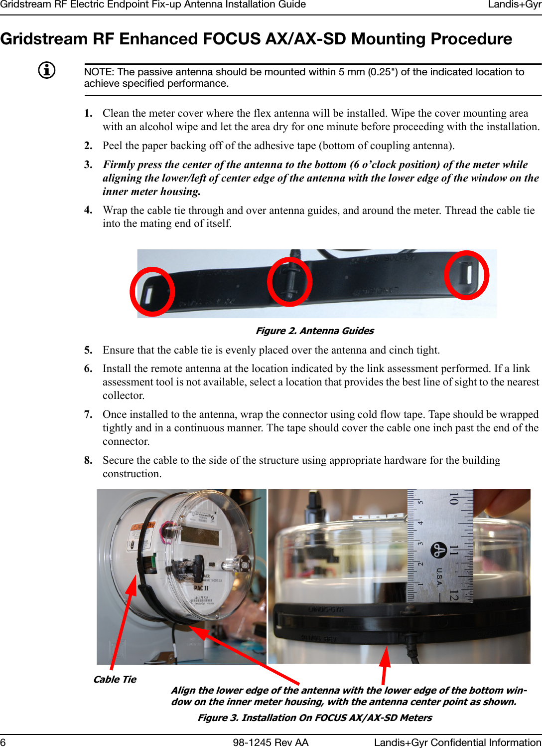
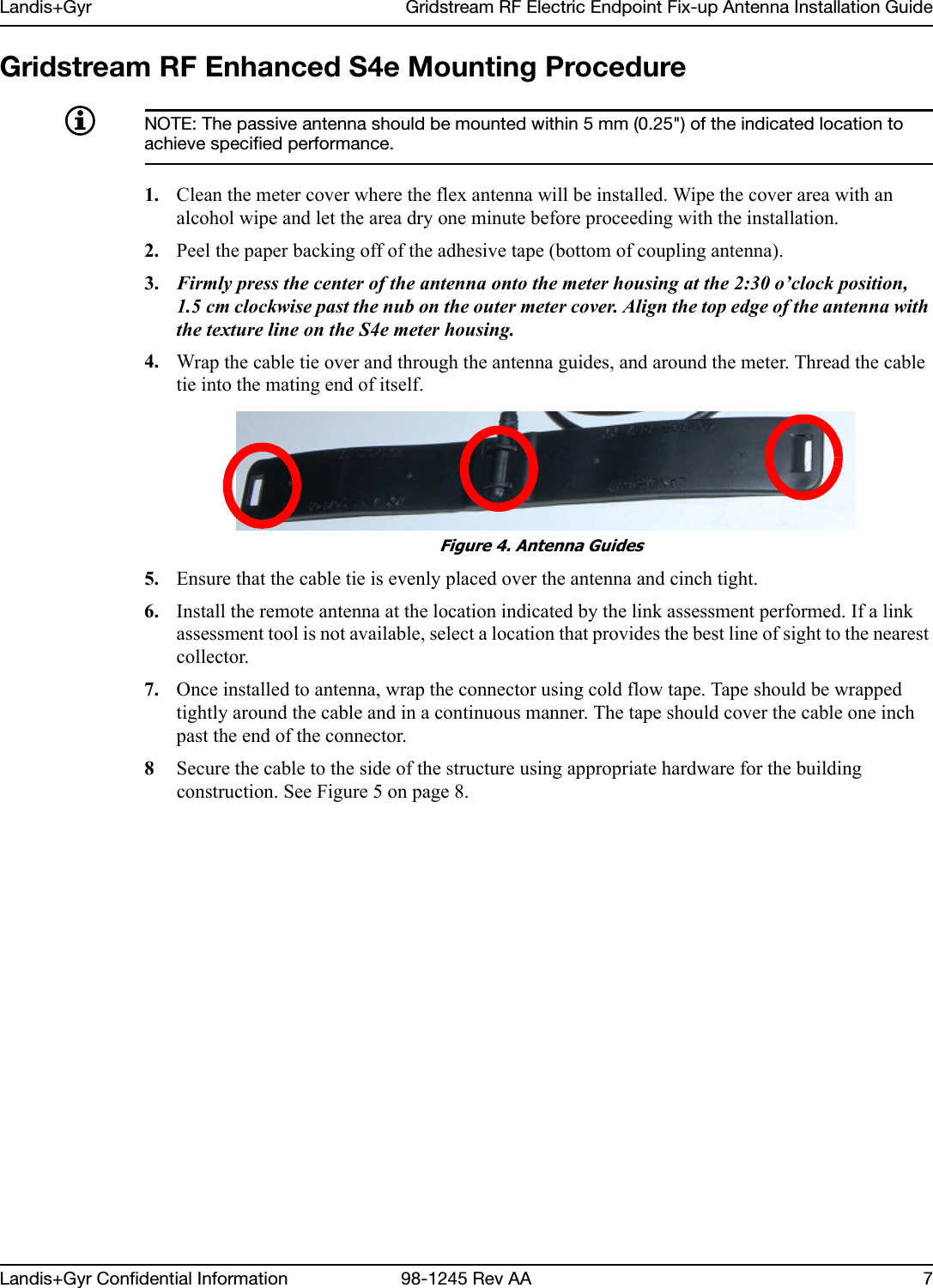
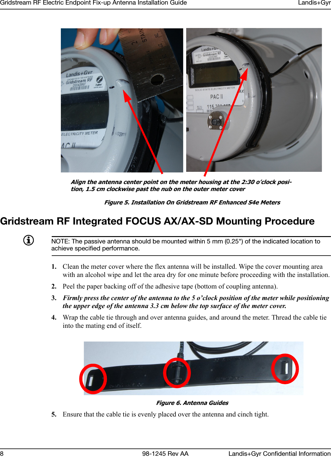
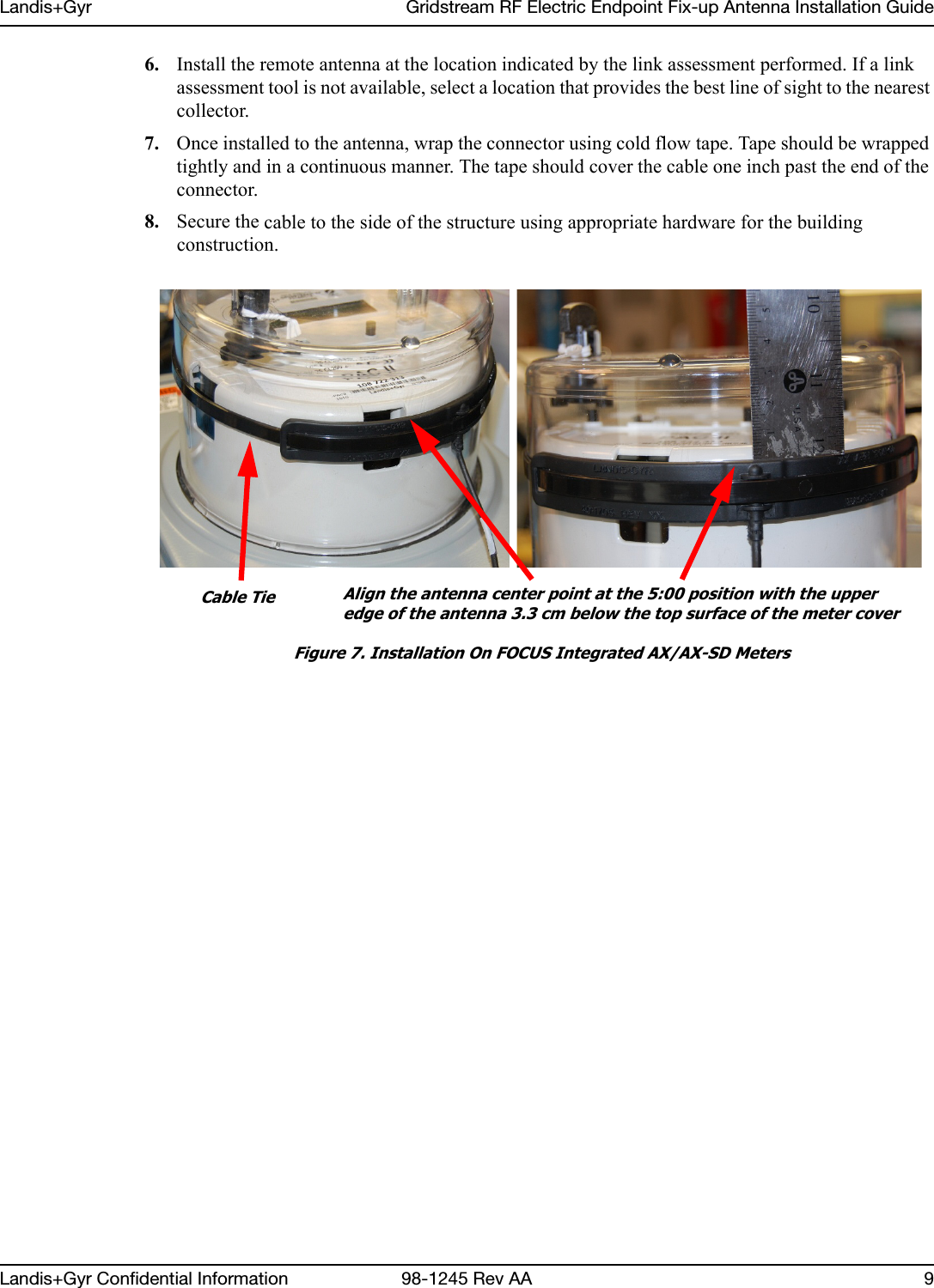
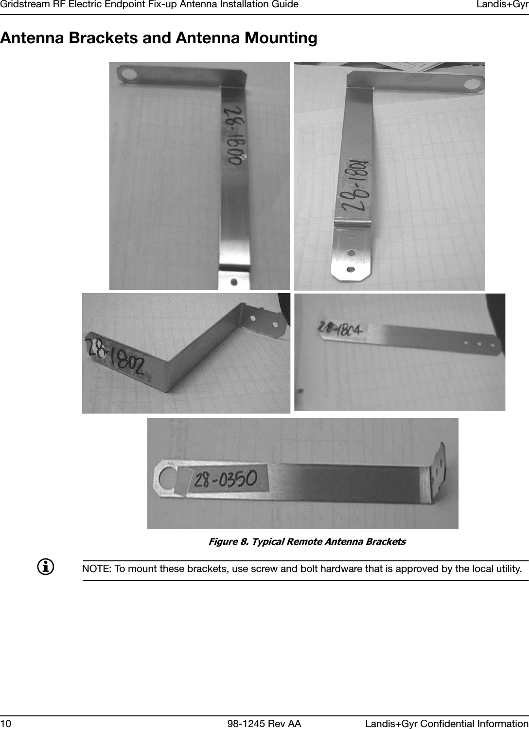
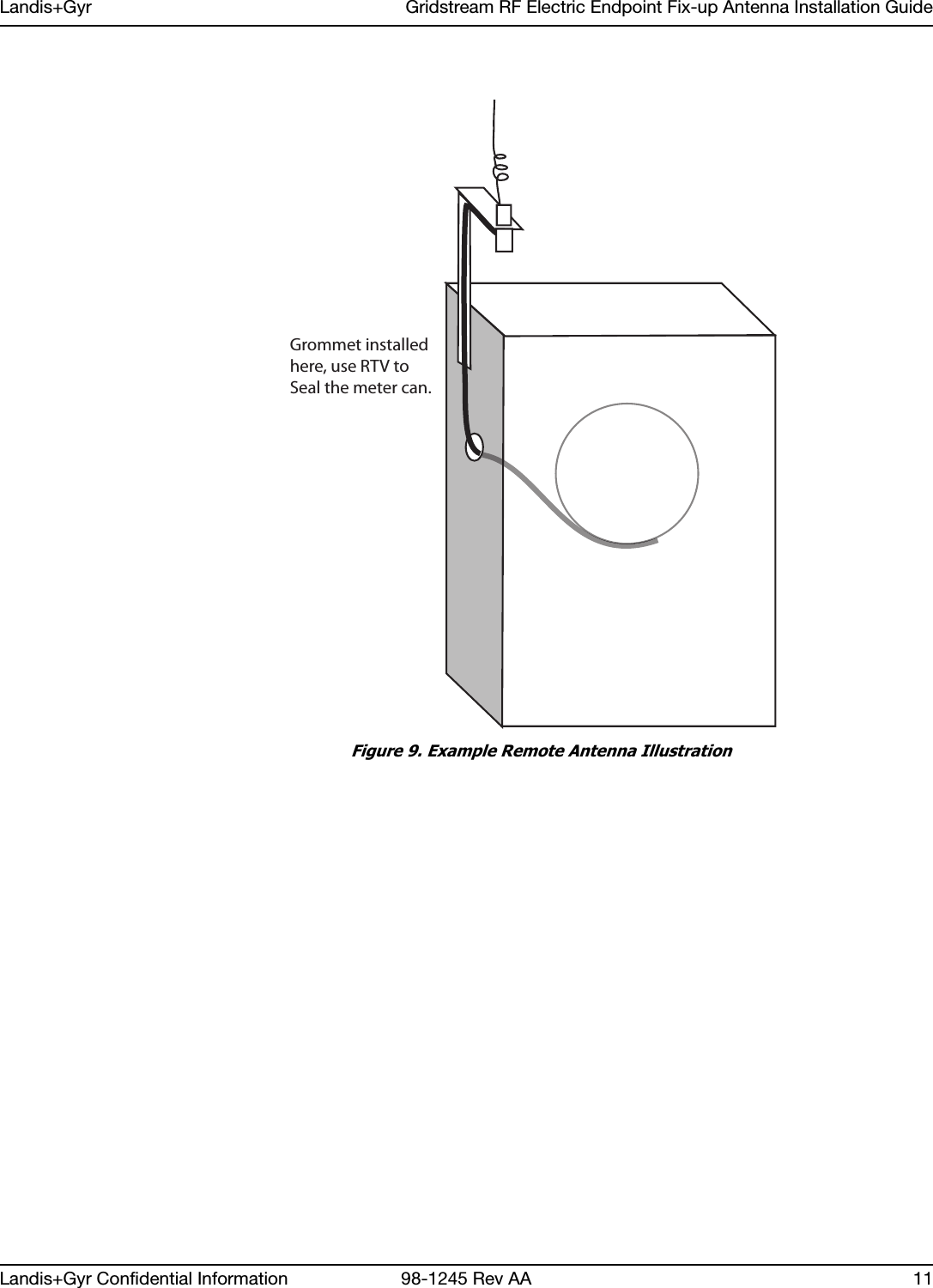
Manual
Manual
Navigation menu
Upload a User Manual
Namespaces
Wiki Guide
HTML
PDF
Info
Views
User Manual
Discussion / Help
Navigation