Landis Gyr Technologies HUNTSU825 3G S4e Gridstream User Manual 12 0333 Exhibit Cover
Landis+Gyr Technologies, LLC 3G S4e Gridstream 12 0333 Exhibit Cover
Contents
- 1. Exhibit D - Product Ship Sheet
- 2. Manual
Manual

5015 B.U. Bowman Drive Buford, GA 30518 USA Voice: 770-831-8048 Fax: 770-831-8598
Certification Exhibit
FCC ID: TEB-HUNTSU825
FCC Rule Part: 15.247
ACS Project Number: 12-0333
Manufacturer: Landis+Gyr Technologies, LLC
Model: 0825

LANDIS+GYR CONFIDENTIAL INFORMATION
Gridstream RF S4e
Endpoint with ZigBee
Data Sheet
Publication: 98-9103 Rev AA
Draft 5.8.13

Limitation on Warranties and Liability
Information in this document is subject to change without notice. This manual or any part of it thereof may not be re-
produced in any form unless permitted by contract or by written permission of Landis+Gyr.
In no event will Landis+Gyr be liable for any incidental, indirect, special, or consequential damages (including lost prof-
its) arising out of or relating to this publication or the information contained in it, even if Landis+Gyr has been advised,
knew, or should have known of the possibility of such damages.
© 2013 Landis+Gyr, Inc. All Rights Reserved
Gridstream RF S4e Endpoint with ZigBee Data Sheet
Publication: Pubs Number Goes Here
Revision History
Modification Date Revision Description Author
05/08/2013 AA Pending Kim Utesch
Landis+Gyr
6436 County Road 11
Pequot Lakes, MN 56472
Website: www.landisgyr.com
E-mail: solutionsupport.na@landisgyr.com
Technical Support: 1-888-390-5733
© 2013 Landis+Gyr
All rights reserved.
Draft 5.8.13
Data Sheet 98-9103 Rev AA 3
Gridstream RF S4e
Endpoint with
ZigBee Data Sheet
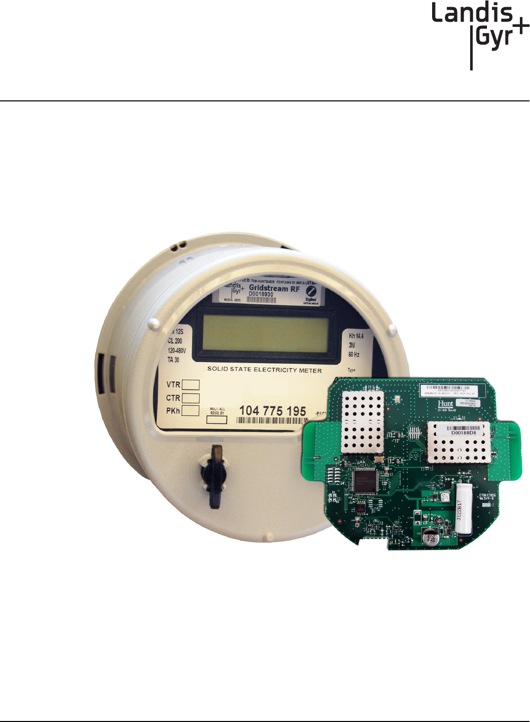
General
The Gridstream RF S4e endpoint is designed to accommodate Landis+Gyr S4e poly-phase meters
for use in commercial and light industrial services. The S4e Advanced Function meter is an Active
Energy kWh/kW/TOU Meter. The meter features Digital Multiplication Measurement Technique,
meets ANSI standards for performance and utilizes ANSI C12.19 protocol (between meter and
AMR device). Can be deployed with or without ZigBee.
Figure 1. The Gridstream RF S4e Endpoint Module and the Landis+Gyr S4e Meter
FCC Compliance Information
Models: 0825, 26-1554, 26-1557
FCC ID: TEB-HUNTSU825
IC: 5931A-HUNTSU825
Draft 5.8.13

Gridstream RF S4e Endpoint with ZigBee Data Sheet Landis+Gyr
4\98-9103 Rev AA Data Sheet
Compliance Statement (Part 15.19)
This device complies with Part 15 of the FCC Rules. Operation is subject to the following two
conditions:
1. This device may not cause harmful interference, and
2. This device must accept any interference received, including interference that may cause
undesired operation.
ACAUTION: Changes or modifications not expressly approved by Landis+Gyr could void the
user’s authority to operate the equipment.
Endpoint Location
To comply with FCC’s RF exposure limits for general population/uncontrolled exposure, the
antenna(e) used for this transmitter must be installed to provide a separation distance of at least 20
cm from all persons and must not be collocated or operating in conjunction with any other antenna or
transmitter.
Industry Canada
This device complies with Industry Canada licence-exempt RSS standard(s). Operation is subject to
the following two conditions: (1) this device may not cause interference, and (2) this device must
accept any interference, including interference that may cause undesired operation of the device.
Under Industry Canada regulations, this radio transmitter may only operate using an antenna of a
type and maximum (or lesser) gain approved for the transmitter by Industry Canada. To reduce
potential radio interference to other users, the antenna type and its gain should be so chosen that the
equivalent isotropically radiated power (e.i.r.p.) is not more than that necessary for successful
communication.
This radio transmitter (5931A-HUNTSU825) has been approved by Industry Canada to operate with
the antenna types listed below with the maximum permissible gain and required antenna impedance
for each antenna type indicated. Antenna types not included in this list, having a gain greater than the
maximum gain indicated for that type, are strictly prohibited for use with this device.
Approved Antenna: Omni-directional antenna, 5.5 dBi gain, 902-928 MHz, antenna impedance is 50
ohms.
Le présent appareil est conforme aux CNR d'Industrie Canada applicables aux appareils radio
exempts de licence. L'exploitation est autorisée aux deux conditions suivantes : (1) l'appareil ne doit
pas produire de brouillage, et (2) l'utilisateur de l'appareil doit accepter tout brouillage
radioélectrique subi, même si le brouillage est susceptible d'en compromettre le fonctionnement.
Conformément à la réglementation d'Industrie Canada, le présent émetteur radio peut fonctionner
avec une antenne d'un type et d'un gain maximal (ou inférieur) approuvé pour l'émetteur par
Industrie Canada. Dans le but de réduire les risques de brouillage radioélectrique à l'intention des
autres utilisateurs, il faut choisir le type d'antenne et son gain de sorte que la puissance isotrope
rayonnée équivalente (p.i.r.e.) ne dépasse pas l'intensité nécessaire à l'établissement d'une
communication satisfaisante.
Draft 5.8.13

Landis+Gyr Gridstream RF S4e Endpoint with ZigBee Data Sheet
Data Sheet 98-9103 Rev AA 5
Le présent émetteur radio (5931A-HUNTSU825) a été approuvé par Industrie Canada pour
fonctionner avec les types d'antenne énumérés ci-dessous et ayant un gain admissible maximal et
l'impédance requise pour chaque type d'antenne. Les types d'antenne non inclus dans cette liste, ou
dont le gain est supérieur au gain maximal indiqué, sont strictement interdits pour l'exploitation de
l'émetteur.
Endpoint Usage
The Gridstream RF S4e endpoint will be used:
•for commercial and light industrial metering applications.
•at homes and businesses.
The Gridstream RF S4e endpoint requires professional installation by qualified personnel.
RF Interference
This equipment has been tested and found to comply with the limits for a Class B digital device,
pursuant to part 15 of the FCC Rules. These limits are designed to provide reasonable protection
against harmful radio frequency energy and, if not installed and used in accordance with the
instructions, may cause harmful interference to radio communications. However, there is no
guarantee that interference will not occur in a particular installation.
If this equipment does cause harmful interference to radio or television reception, which can be
determined by turning the meter off, the user is encouraged to try to correct the interference by one
or more of the following measures:
•Re-orient or relocate the receiving antenna.
•Increase the separation between the equipment and receiver.
•Consult Landis+Gyr or an experienced radio/TC technician for help.
Required Software
To work with the endpoint, you need one of the following software tools:
•Command Center host ver. 4.1 SP2 or greater
•RadioShop
•Landis+Gyr 1132Prog application
•Endpoint Testing Manager
Draft 5.8.13

Gridstream RF S4e Endpoint with ZigBee Data Sheet Landis+Gyr
6\98-9103 Rev AA Data Sheet
Communication Module Specifications
Table -1. Gridstream RF S4e Communications Module Specifications
Category Specification Value or Range
Compatible
Meters
Landis+Gyr S4e Supported
Meter Forms
Form Class Form Class
3S 20 16SE 320
5S/45S 20 16/15K 480
6S/36S 20
9S/8S 20
2S 200
12S 200
16S/15S 200
25S 200
12SE 320
Electrical
Voltage 10.5-13.5V (from the meter’s power supply)
Power Max: 2.5W
Typic a l : 0 .5 W
RF 900 MHz
Output Power +26 dBm +/-1 dBm
Adjacent Channel Power 39 dBc Nominal (9600 bps)
Transmit Frequency 902 to 928 MHz ISM unlicensed (FCC Part 15)
Communication Protocol Gridstream Protocol for Command Center
Receive Sensitivity -108 dBm minimum
RF ZigBee
Output Power +20 dBm +/-1
Adjacent Channel Power 40 dBc Minimum
Transmit Frequency 2405-2480 MHz
Communication Protocol ZigBee Protocol
Receive Sensitivity -104 dBm minimum
Standards
Compliance
FCC Title 47 CFR Part 15 Radiated and Conducted Emissions (incl.
intentional radiators)
IEC 61000 4-2,3,4,5,11,12 Electromagnetic Compatibility
ANSI C12.19 Compatible with Utility Industry End Device Tables
ANSI C12.20 National Standard for Electricity Meters - 0.2 and
0.5 Accuracy Classes
ANSI C12.1 Code for Electricity Metering
ANSI C37.90.1 (1989) Standard Surge Withstand Capability (SWC) Tests
ANSI C12.22 Transport of ANSI C12.19 Over Network
Transmissions
Draft 5.8.13

Landis+Gyr Gridstream RF S4e Endpoint with ZigBee Data Sheet
Data Sheet 98-9103 Rev AA 7
Environmental
General Environmental Outdoor, rain-protected, sunlight-exposed
Operating Temperature Range -40 to +85 C (under meter cover)
Humidity 0 to 95% relative humidity, non-condensing
Table -1. Gridstream RF S4e Communications Module Specifications (Continued)
Category Specification Value or Range
Draft 5.8.13

LANDIS+GYR CONFIDENTIAL INFORMATION
Gridstream
RF Electric Endpoint
Fix-up Antenna
Installation Guide
Publication: 98-1245 Rev AA

Limitation on Warranties and Liability
Information in this document is subject to change without notice. This manual or any part of it thereof may not be re-
produced in any form unless permitted by contract or by written permission of Landis+Gyr.
In no event will Landis+Gyr be liable for any incidental, indirect, special, or consequential damages (including lost prof-
its) arising out of or relating to this publication or the information contained in it, even if Landis+Gyr has been advised,
knew, or should have known of the possibility of such damages.
All brands and product names are the trademarks or registered trademarks of their respective holders.
© 2013 Landis+Gyr, Inc. All Rights Reserved
Gridstream RF Electric Endpoint Fix-up Antenna Installation Guide
Publication: 98-1245
Revision History
Modification Date Revision Description Author
3/26/2013 AA Released Vicky Costello
Landis+Gyr
30000 Mill Creek Avenue
Alpharetta, GA 30022
Website: www.landisgyr.com
E-mail: solutionsupport.na@landisgyr.com
Technical Support: 1-888-390-5733
© 2013 Landis+Gyr
All rights reserved.
Landis+Gyr Confidential Information 98-1245 Rev AA 3
Gridstream RF Electric
Endpoint Fix-up Antenna
Installation Guide
Overview
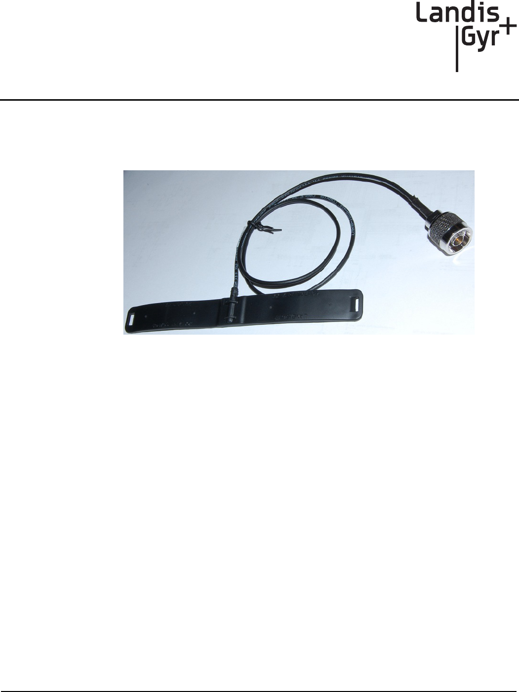
This publication outlines the procedure for remote passive antenna installation on Gridstream RF
Electric Endpoints.
Figure 1. Remote Passive Antenna
This antenna couples radio frequency energy from a Landis+Gyr Gridstream RF Electric Endpoint's
902-928 MHz antenna into a coax cable connected to a remote antenna located at an optimal location
for better connection to the Gridstream RF network. Coupling loss (including the 2.5 ft. cable)
ranges from 5 to 9 dB, with 5 being a typical value. Environmental performance is rated for: 0 to
95% relative humidity, -40 to +85° C.
Coupler Part Numbers
The same coupler is used for all remote antenna installations. The part number and description is as
follows:
•40-1705 flex loop, 2.5 ft. antenna cable, cable tie, adhesive
In the case where the length above is insufficient, Landis+Gyr recommends the extension cable
listed below, terminated with a female “N” connector on one end and a male “N” connector on the
other:
•19-1742, extension cable, 20 ft.

Gridstream RF Electric Endpoint Fix-up Antenna Installation Guide Landis+Gyr
4 98-1245 Rev AA Landis+Gyr Confidential Information
Required Materials
The following materials are required to complete a remote antenna installation.
•Alcohol wipes
•RTV - Part Number 30-0109, Dow Corning #839
•Cold flow sealing tape
•Hardware, appropriate to installation
•45-1221, Kit, Antenna (consisting of items listed below)
•106119-000 Remote Antenna, 5dBi Whip
•28-1012, Antenna Ground Plane
•16-0214: Barrel Connector N-Female to N-Female, “Bulkhead”
List of Terms
The following is a list of terms used to identify remote antennas and related equipment.
Coupling Antenna
This is the flexible circuit that is at the end of the antenna assembly. It is referred to interchangeably
as the flex circuit, flex dipole, patch antenna, coupler, and so on.
Remote Antenna
Refers to the omni whip antenna which will be “remoted” from the coupling antenna. The remote
antenna is ideally mounted “line of sight” to the Gridstream RF Mesh network.
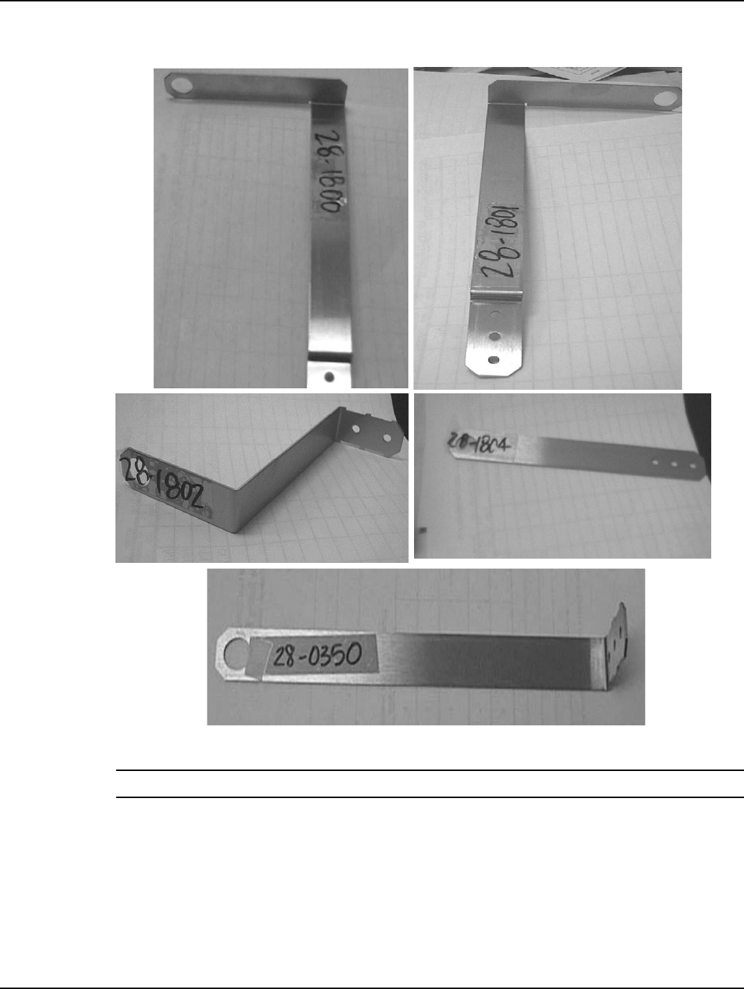
Optional Materials
The following items may be required, depending on the installation.
•22-1542: Grommet, 1.25” OD, 1.0” ID with 0.25” center hole
•Mounting brackets, Landis+Gyr part numbers:
•28-1800: Bracket, antenna, meter box, right
•28-1801: Bracket, antenna, meter box, left
•28-1802: Bracket, antenna, ceiling mount
•28-1804: Bracket, antenna, wall, flat
To o l s
The following tools may be required, depending on the installation.
• Flat head screwdriver • Phillips head screwdriver
• Utility knife • Wire cutters
• Battery-operated drill with 5/8- and 1-inch
high speed metal bits
• Tape measure

Landis+Gyr Gridstream RF Electric Endpoint Fix-up Antenna Installation Guide
Landis+Gyr Confidential Information 98-1245 Rev AA 5
Performance
Table 1. Performance
Parameter Minimum Typical Maximum Units Condition
Frequency 902 928 MHz
Coupling
Loss
5 9 dB
Polarization Linear
VSWR 1.78:1 Final antenna assembly on FOCUS
AX: modular
Impedance 50 ohm
Input RL 11 dB Final antenna assembly on FOCUS
AX: modular
General Installation Guidelines
Determine the optimum location for remote antenna installation. This will vary depending on the
location of the meter. In general, the antenna should be:
•Installed as close to line of sight with a Gridstream RF network equipment as is possible.
•Mounted so that it is at least four inches from the nearest structure.
•Mounted so that a meter box cover, if the endpoint is enclosed in one, can be removed
without interference from the remoted antenna.
•For inside-premise installations, remoted antennas may be mounted in the proximity of an
available window, or may need to be routed to the outside if the signal strength is
insufficient.
•Mounted so that the antenna connector is OUTSIDE the meter box. A 1-inch hole should be
drilled in the meter box so that the connector can be fed through the box. Use the appropriate
mounting bracket to mount the antenna external to the meter box.
•Mounted so that any length of additional cable is minimized. The best practice for maximum
cable length is to not exceed line loss (refer to cable manufactures line loss chart) vs. gain of
antenna, the RF link loss by use of passive antenna can be excluded from the line loss
calculation.
It is the responsibility of local installation organizations to ensure that local wiring codes and
requirements are met, including the application of a safety ground, when required.
NOTE: This device and the supplied installation components are UV-resistant.
Gridstream RF Electric Endpoint Fix-up Antenna Installation Guide Landis+Gyr
6 98-1245 Rev AA Landis+Gyr Confidential Information
Gridstream RF Enhanced FOCUS AX/AX-SD Mounting Procedure
NOTE: The passive antenna should be mounted within 5 mm (0.25") of the indicated location to
achieve specified performance.
1. Clean the meter cover where the flex antenna will be installed. Wipe the cover mounting area
with an alcohol wipe and let the area dry for one minute before proceeding with the installation.
2. Peel the paper backing off of the adhesive tape (bottom of coupling antenna).
3. Firmly press the center of the antenna to the bottom (6 o’clock position) of the meter while
aligning the lower/left of center edge of the antenna with the lower edge of the window on the
inner meter housing.
4. Wrap the cable tie through and over antenna guides, and around the meter. Thread the cable tie
into the mating end of itself.
Figure 2. Antenna Guides
5. Ensure that the cable tie is evenly placed over the antenna and cinch tight.
6. Install the remote antenna at the location indicated by the link assessment performed. If a link
assessment tool is not available, select a location that provides the best line of sight to the nearest
collector.
7. Once installed to the antenna, wrap the connector using cold flow tape. Tape should be wrapped
tightly and in a continuous manner. The tape should cover the cable one inch past the end of the
connector.
8. Secure the cable to the side of the structure using appropriate hardware for the building
construction.
Cable Tie
Align the lower edge of the antenna with the lower edge of the bottom win-
dow on the inner meter housing, with the antenna center point as shown.
Figure 3. Installation On FOCUS AX/AX-SD Meters
Landis+Gyr Gridstream RF Electric Endpoint Fix-up Antenna Installation Guide
Landis+Gyr Confidential Information 98-1245 Rev AA 7
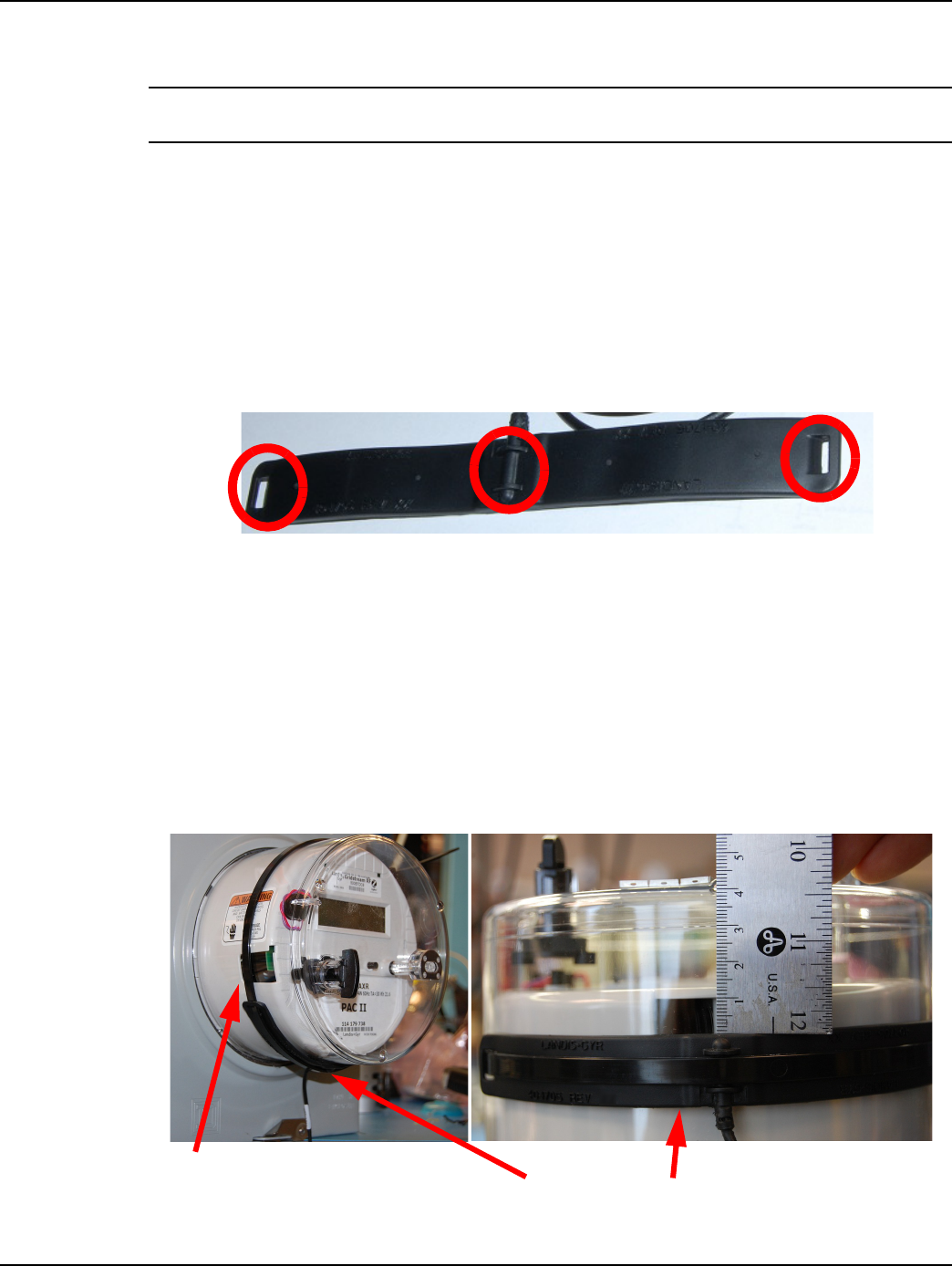
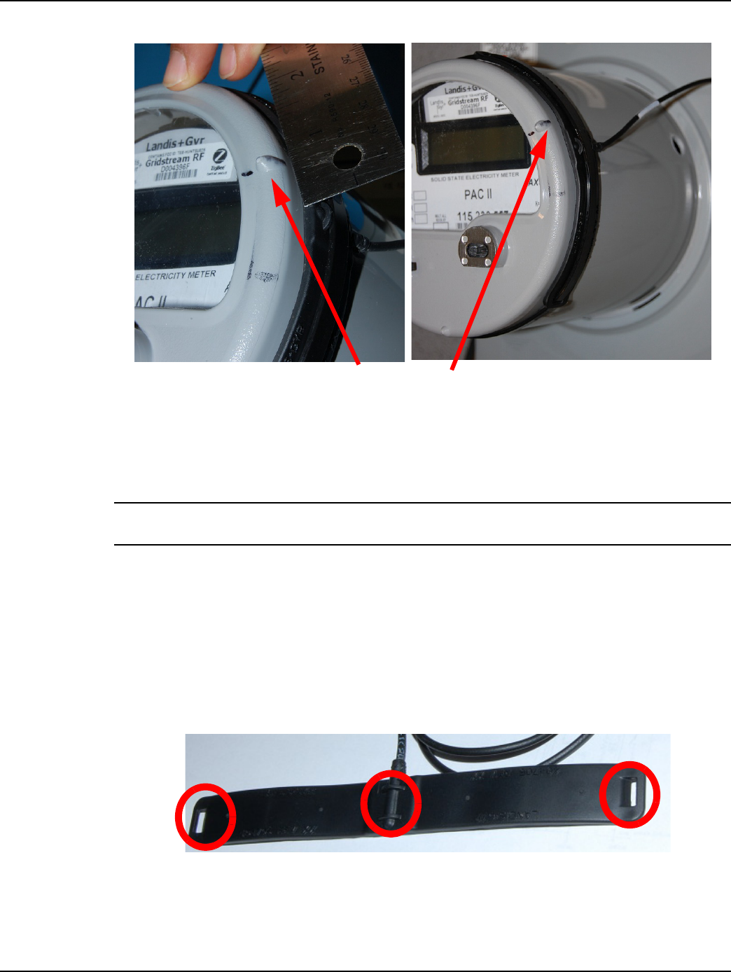
Gridstream RF Enhanced S4e Mounting Procedure
NOTE: The passive antenna should be mounted within 5 mm (0.25") of the indicated location to
achieve specified performance.
1. Clean the meter cover where the flex antenna will be installed. Wipe the cover area with an
alcohol wipe and let the area dry one minute before proceeding with the installation.
2. Peel the paper backing off of the adhesive tape (bottom of coupling antenna).
3. Firmly press the center of the antenna onto the meter housing at the 2:30 o’clock position,
1.5 cm clockwise past the nub on the outer meter cover. Align the top edge of the antenna with
the texture line on the S4e meter housing.
4. Wrap the cable tie over and through the antenna guides, and around the meter. Thread the cable
tie into the mating end of itself.
Figure 4. Antenna Guides
5. Ensure that the cable tie is evenly placed over the antenna and cinch tight.
6. Install the remote antenna at the location indicated by the link assessment performed. If a link
assessment tool is not available, select a location that provides the best line of sight to the nearest
collector.
7. Once installed to antenna, wrap the connector using cold flow tape. Tape should be wrapped
tightly around the cable and in a continuous manner. The tape should cover the cable one inch
past the end of the connector.
8Secure the cable to the side of the structure using appropriate hardware for the building
construction. See Figure 5 on page 8.
Align the antenna center point on the meter housing at the 2:30 o’clock posi-
tion, 1.5 cm clockwise past the nub on the outer meter cover
Gridstream RF Electric Endpoint Fix-up Antenna Installation Guide Landis+Gyr
8 98-1245 Rev AA Landis+Gyr Confidential Information
Figure 5. Installation On Gridstream RF Enhanced S4e Meters
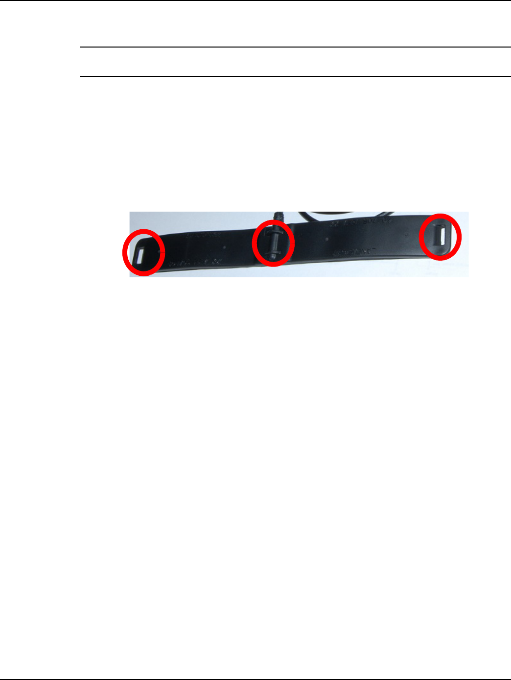
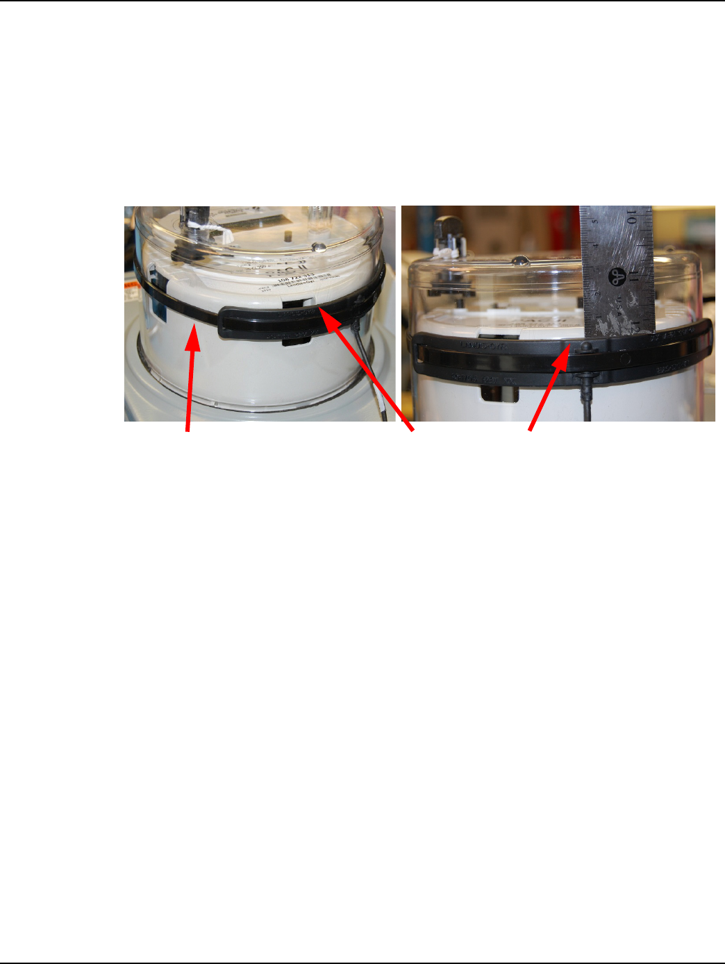
Gridstream RF Integrated FOCUS AX/AX-SD Mounting Procedure
NOTE: The passive antenna should be mounted within 5 mm (0.25") of the indicated location to
achieve specified performance.
1. Clean the meter cover where the flex antenna will be installed. Wipe the cover mounting area
with an alcohol wipe and let the area dry for one minute before proceeding with the installation.
2. Peel the paper backing off of the adhesive tape (bottom of coupling antenna).
3. Firmly press the center of the antenna to the 5 o’clock position of the meter while positioning
the upper edge of the antenna 3.3 cm below the top surface of the meter cover.
4. Wrap the cable tie through and over antenna guides, and around the meter. Thread the cable tie
into the mating end of itself.
Figure 6. Antenna Guides
5. Ensure that the cable tie is evenly placed over the antenna and cinch tight.
Landis+Gyr Gridstream RF Electric Endpoint Fix-up Antenna Installation Guide
Landis+Gyr Confidential Information 98-1245 Rev AA 9
6. Install the remote antenna at the location indicated by the link assessment performed. If a link
assessment tool is not available, select a location that provides the best line of sight to the nearest
collector.
7. Once installed to the antenna, wrap the connector using cold flow tape. Tape should be wrapped
tightly and in a continuous manner. The tape should cover the cable one inch past the end of the
connector.
8. Secure the cable to the side of the structure using appropriate hardware for the building
construction.
Cable Tie Align the antenna center point at the 5:00 position with the upper
edge of the antenna 3.3 cm below the top surface of the meter cover
Figure 7. Installation On FOCUS Integrated AX/AX-SD Meters
Gridstream RF Electric Endpoint Fix-up Antenna Installation Guide Landis+Gyr
10 98-1245 Rev AA Landis+Gyr Confidential Information
Antenna Brackets and Antenna Mounting
Figure 8. Typical Remote Antenna Brackets
NOTE: To mount these brackets, use screw and bolt hardware that is approved by the local utility.

Grommet installed
here, use RTV to
Seal the meter can.
Landis+Gyr Gridstream RF Electric Endpoint Fix-up Antenna Installation Guide
Landis+Gyr Confidential Information 98-1245 Rev AA 11
Figure 9. Example Remote Antenna Illustration