Landis Gyr Technology ER0R1S2 Water Meter Data Transmitter User Manual Installation Guide
Landis+Gyr Technology, Inc. Water Meter Data Transmitter Installation Guide
Installation Guide

5015 B.U. Bowman Drive Buford, GA 30518 USA Voice: 770-831-8048 Fax: 770-831-8598
Certification Exhibit
FCC ID: R7PER0R1S2
IC: 5294A-ER0R1S2
FCC Rule Part: 15.247
IC Radio Standards Specification: RSS-210
ACS Report Number: 08-0302-15C
Manufacturer: Cellnet Technology, Inc.
Model: CWE WALL 2G
Installation Guide

Cellnet Water Endpoint 6060
Remote Installation Guide
98-1552
Limitation on Warranties and Liability
Information in this document is subject to change without notice. This manual or any part of it thereof may not be
reproduced in any form unless permitted by contract or by written permission of Landis+Gyr.
In no event will Landis+Gyr be liable for any incidental, indirect, special, or consequential damages (including lost
profits) arising out of or relating to this publication or the information contained in it, even if Landis+Gyr has been
advised, knew, or should have known of the possibility of such damages.
© 2008 Landis+Gyr. All Rights Reserved.
Trademarks
Cellnet® is a registered trademark of Cellnet Innovations, Inc.
Other brands or product names are the trademarks or registered trademarked of their respective holders.

CWE 6060 Remote Installation Guide 98-1552 i
Table of Contents
Chapter 1: Introduction . . . . . . . . . . . . . . . . . . . . . . . . . . . . . . . . . . . . . . . . . . . . . . . . . . . . . . . . . . . . . . 1
Chapter 2: Installing the Cellnet Water Endpoint . . . . . . . . . . . . . . . . . . . . . . . . . . . . . . . . . . . . . . . . . . 7
Chapter 3: Testing the Endpoint . . . . . . . . . . . . . . . . . . . . . . . . . . . . . . . . . . . . . . . . . . . . . . . . . . . . . . 15
Chapter 4: Endpoint Replacement . . . . . . . . . . . . . . . . . . . . . . . . . . . . . . . . . . . . . . . . . . . . . . . . . . . . 17
Chapter 5: Troubleshooting . . . . . . . . . . . . . . . . . . . . . . . . . . . . . . . . . . . . . . . . . . . . . . . . . . . . . . . . . 19
Appendix A: Crimping Wires . . . . . . . . . . . . . . . . . . . . . . . . . . . . . . . . . . . . . . . . . . . . . . . . . . . . . . . . . 21
Glossary . . . . . . . . . . . . . . . . . . . . . . . . . . . . . . . . . . . . . . . . . . . . . . . . . . . . . . . . . . . . . . . . . . . . . . . . . 25

Landis+Gyr
ii 98-1552 CWE 6060 Remote Installation Guide
1
CWE 6060 Remote Installation Guide 98-1552 1
Introduction
This manual explains how to correctly install Cellnet Water Endpoints (CWE) for remote
applications. It covers endpoint installation, encoder register connection, and troubleshooting.
Tools and Equipment
This section outlines the necessary tools and equipment for installing a Cellnet Water Endpoint for
remote applications.
Equipment
The following table contains all required equipment:
Table 1-1. CWE Installation Equipment
Image Description
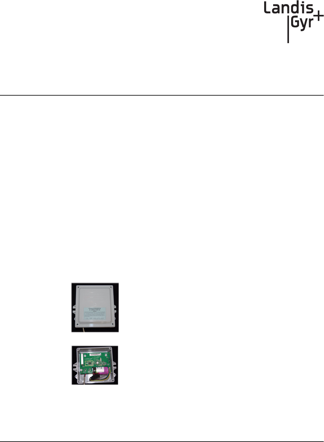
`ÉääåÉí=t~íÉê=båÇéçáåí=jçÇÉä=SMSMJ=oÉãçíÉ=ïáíÜ=iÉ~ÇëI=
páåÖäÉ=mçêí
Chapter 1 - Introduction Landis+Gyr
2 98-1552 CWE 6060 Remote Installation Guide
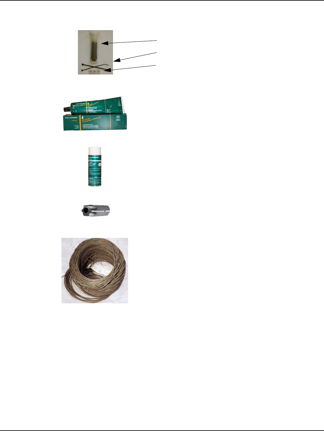
_~ÇÖÉê=cáÉäÇ=péäáÅÉ=háí=SOMUQJMMN
Splice Enclosure
Tie wraps
3M Scotchloks, Model UY2 or Equivalent
açï=`çêåáåÖ=Q=bäÉÅíêáÅ~ä=fåëìä~íáåÖ=`çãéçìåÇ=Eçê=Éèìáî~äÉåíF
jpap=~î~áä~ÄäÉ=~í=ïïïKÇçïÅçêåáåÖKÅçãK
açï=`çêåáåÖ=lpJO=ëáäáÅçåÉ=`äÉ~åÉê=Eçê=Éèìáî~äÉåíF
jpap=~î~áä~ÄäÉ=~í=ïïïKÇçïÅçêåáåÖKÅçãK
mfkJfkJqlou
oÉèìáêÉë=~=qlou=ÇêáîÉê=ëáòÉ=qNM=ïáíÜ=~=ÜçäÉ=Ñçê=íÜÉ=mfk
^ÇÇáíáçå~ä=Å~ÄäÉ
péÉÅáÑáÅ~íáçåW=OOJ^td=pçäáÇ=`çééÉê
`çäçêëW=oÉÇLdêÉÉåL_ä~Åâ
ms`=g~ÅâÉí
Image Description
Landis+Gyr Chapter 1 - Introduction
CWE 6060 Remote Installation Guide 98-1552 3
Tools
The following table contains all required tools:
Table 1-2. CWE Installation Equipment
Image Description
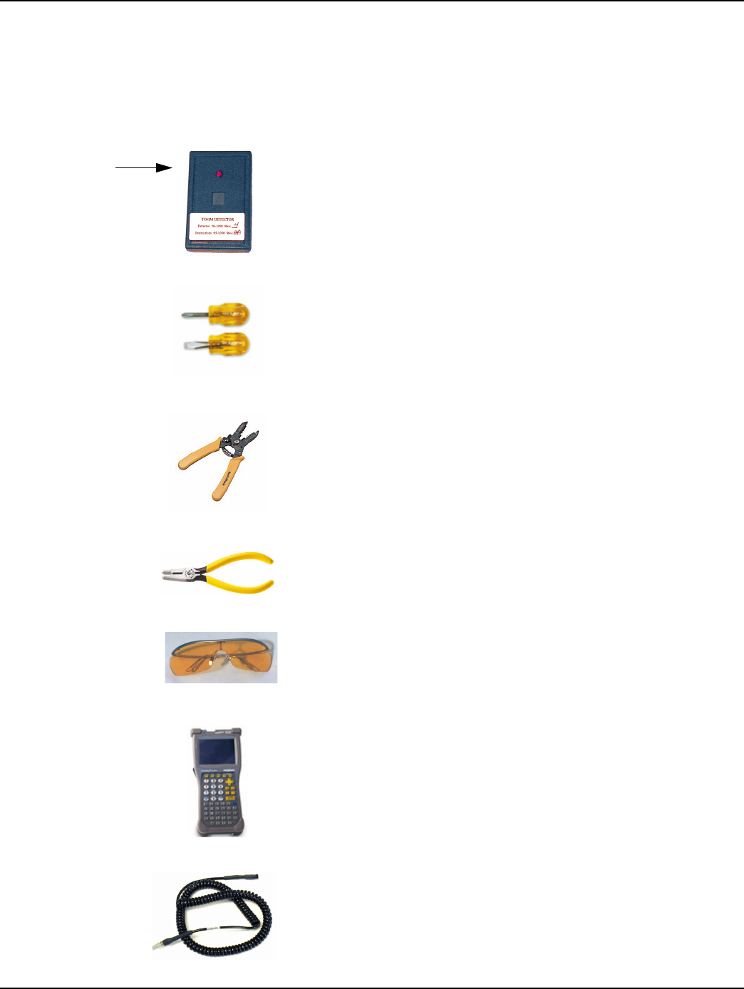
oc=_ìëíÉê
mLk=OSJNMRM
Ej~ÖåÉí=áë=~í=ìééÉê=äÉÑí=~ë=ëÜçïå=ïáíÜ=~êêçïF
pÅêÉïÇêáîÉêë=EÑä~í=~åÇ=mÜáääáéëF
táêÉ=`ìííÉê=~åÇ=píêáééÉê
pÅçíÅÜäçâ®=bJVv=`êáãéáåÖ=qççä=çê=bèìáî~äÉåí
ïïïKPjKÅçã
p~ÑÉíó=dçÖÖäÉë
e~åÇeÉäÇ=`çãéìíÉê=
ïïïKÇ~éKÅçã
`ÉääåÉí=oÉãçíÉ=t~íÉê=båÇéçáåí=mêçÖê~ããáåÖ=`~ÄäÉ

Chapter 1 - Introduction Landis+Gyr
4 98-1552 CWE 6060 Remote Installation Guide
Safety and Environment
Prerequisite Training
Installers should be instructed in the following safety elements as well as any site-specific safety
issues:
• Hazard Communication (Employee Right to Know)
• Lifting
• Safe driving
• Use of hand tools
• Confined space
Preliminary Checks
The installer should already be able to operate the HandHeld computer. Additionally, you should
already have route information and the required number of endpoints.
• Verify that you are at the correct site, specified on the handheld computer or work order.
• Verify that the site is safe for you and your equipment.
• Notify the customer of your presence. Tell the customer that you must have access to the water
meter. If necessary, have the customer sign the work order.
• When installing meters, follow any guidelines issued by your company in addition to those
given in this guide.
• Never perform an installation during a lightning storm or under excessively wet conditions.
Site Requirements
The site must comply with the following criteria:
• There is no chance that another object will be set over the antenna.
• Some instances may require additional cable.
• Maximum cable length is always 200 feet.
kÉéíìåÉ=mêçoÉ~Ç=cáÉäÇ=mêçÖê~ããÉê=Eåçí=êÉèìáêÉÇ=Ñçê=^ìíç=çê=
^o_=S=ÉåÅçÇÉêëF
ïïïKåÉéíìåÉíÖKÅçã
Image Description

Landis+Gyr Chapter 1 - Introduction
CWE 6060 Remote Installation Guide 98-1552 5
FCC & Industry Canada Information to the User
FCC Class B
This equipment has been tested and found to comply with the limits for a Class B digital device,
pursuant to Part 15 of the FCC Rules. These limits are designed to provide reasonable protection
against harmful interference in a residential installation. This equipment generates, uses, and can
radiate radio frequency energy and, if not installed and used in accordance with the Instructions, may
cause harmful interference to radio communications. However, there is no guarantee that
interference will not occur in a particular installation. If this equipment does cause harmful
interference to radio or television reception, which can be determined by turning the equipment off
and on, the user is encouraged to try to correct the interference by one or more of the following
measures:
• Reorient or relocate the receiving antenna.
• Increase the separation between the equipment and receiver.
• Consult Cellnet or an experienced radio technician for help.
RF Exposure
In accordance with FCC requirements of human exposure to radio frequency fields, the radiating
element shall be installed such that a minimum separation distance of 20 centimeters will be
maintained.
Industry Canada
This Class B digital apparatus meets all requirements of the Canadian Interference Causing
Equipment Regulations. Operation is subject to the following two conditions: (1) this device may not
cause harmful interference, and (2) this device must accept any interference received, including
interference that may cause undesired operation.
Cet appareillage numérique de la classe B répond à toutes les exigences de l'interférence canadienne
causant des règlements d'équipement. L'opération est sujette aux deux conditions suivantes: (1) ce
dispositif peut ne pas causer l'interférence nocive, et (2) ce dispositif doit accepter n'importe quelle
interférence reçue, y compris l'interférence qui peut causer l'opération peu désirée.
Changes or modifications to this device not expressly approved by Cellnet
Technology, Inc. could void the user's authority to operate the equipment.

Chapter 1 - Introduction Landis+Gyr
6 98-1552 CWE 6060 Remote Installation Guide
FCC ID: R7PER0R1S2
This device complies with Part 15 of the FCC rules. Operation is subject to the following two
conditions:
(1) This device may not cause harmful interference, and
(2) This device must accept any interference received, including interference that may cause
undesired operation.
IC: 5294A-ER0R1S2
This Class B digital apparatus complies with Canadian ICES-003.
Cet appareil numérique de la classe B est conforme à la norme NMB-003 du Canada.
2
CWE 6060 Remote Installation Guide 98-1552 7
Installing the Cellnet Water
Endpoint
Locating the CWE
The CWE Remote should be mounted above ground. If there is an existing touchpad or remote, then
put the new remote in that location. It is preferred to mount the CWE outdoors, to a wall facing the
nearest concentrator.
Mounting the CWE
Mounting techniques vary widely, depending on the physical characteristics of the customer site.
The mounting technique used is left to the installer’s best judgement and experience.
Identifying the Register for Installation
Register connecting instructions listed by register type:
• If the register has screw terminals, proceed to "Connecting a Neptune Auto, Sensus Encoder, or
AMCO Scancoder Register with Screw Terminals" on page -8
Chapter 2 - Installing the Cellnet Water Endpoint Landis+Gyr
8 98-1552 CWE 6060 Remote Installation Guide
• If the register has potted leads, proceed to "Connecting a Badger, Neptune Auto, Sensus Encoder,
or AMCO Scancoder Register with Potted Leads" on page -11
•"UPro-Read Encoder Register" on page -13
Connecting a Neptune Auto, Sensus Encoder, or AMCO Scancoder
Register with Screw Terminals
Remove terminal cover. Use clean, disposable towels or rags to wipe the gel away from the terminals
and screws. After the gel is removed, disconnect any wires connected to the terminals. Clean the
terminals and screws again using Dow Corning OS-2 Silicone Cleaner or equivalent. Be careful not
to lose any screws when disconnecting the wires or cleaning the screw terminals.
If the cable to be connected to the screw terminals has been pre-stripped, proceed to step 3 below.
1Usingthe#10AWGposition(secondlargesthole)onthe64‐1919wirestripper,remove1.5
inchesofexternalinsulationfromthecable.
Figure 2 - 1. 64-1919 Wire stripper
Do not damage the internal wire insulation when removing the external insulation.
Landis+Gyr Chapter 2 - Installing the Cellnet Water Endpoint
CWE 6060 Remote Installation Guide 98-1552 9
2Usingthe#22AWGholeofthewire‐strippingtool,stripone‐halfinchofinsulationfromeachof
thethreeinternalwires.
Figure 2 - 2. Wire stripper
3 Connectthethree‐conductorwiretotheencoderregisterʹsterminals,matchingcolorscarefully.
Threadthecablearoundthestrainreliefpostsoftheencoderregister.
Figure 2 - 3. Threading the cable around the strain relief posts
4Applymoistureprotectioncompoundtoterminalscrewsandexposedwires(DowCorning
Compound#4orNovagard®G661™)
Figure 2 - 4. Applying moisture compound
5Snapthecoverontotheencoderregister.
6Wipeawayexcesscompound.
7RouteencodercablefromencodertothemountedlocationoftheCWERemote.
8 MounttheCWERemote
9SplicethewiresfromtheCWERemotetothethreewiresfromtheencodercable.
Position the end of the cable jacket so that the compound will cover
it and it will not be visible when the cover is installed, as shown.
Be sure that the waterproofing compound completely seals the wires. Apply compound under
the cable and individual wires. Cover the top of the cable, wires, and screws. Use enough
compound so it flows from openings when the cover is attached.
Chapter 2 - Installing the Cellnet Water Endpoint Landis+Gyr
10 98-1552 CWE 6060 Remote Installation Guide
10 Matchthecolorscarefullyusingthefollowingtable
.
11 SeeAppendixA,CrimpingWires,forinstructionsoncrimpingthewires.
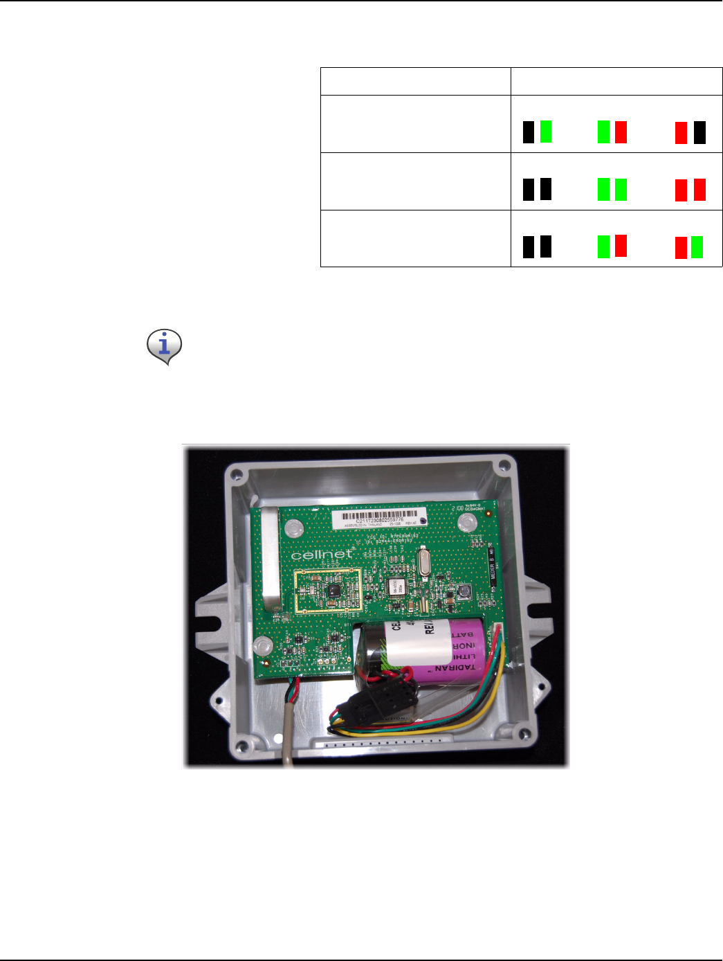
12 DresswiresinsidetheCWERemoteenclosureasshown.
13 ProceedtoTestingtheEndpoint.
Table 1 Color Matching
Encoder Register 6060 Wire Color/Encoder Terminal
kÉéíìåÉ=mêçoÉ~Ç=E^o_=sfF Blk/Green Green/R Red/B
pÉåëìë=b`oJffI=b`oJfff=Ef`bF Blk/Blk Green/G Red/R
^j`l=pÅ~åÅçÇÉê Blk/Blk Green/G Red/R
All color translations will be done at the CWE Remote. If using existing wire, verify that
no color translations are present. If color translations have occurred, replace the
splices if possible. Replace the cable to prevent confusion due to double translation.
Landis+Gyr Chapter 2 - Installing the Cellnet Water Endpoint
CWE 6060 Remote Installation Guide 98-1552 11
Connecting a Badger, Neptune Auto, Sensus Encoder, or AMCO
Scancoder Register with Potted Leads
Use the following installation procedure for sites equipped with potted encoders.
1RoutethecablefromthepottedregistertotheCWEmountinglocation.Spliceinadditional
cableasnecessary.Whenusingadditionalcable,alwaysmatchcolors:blacktoblack,redtored,
greentogreen.AllcolortranslationswillbedoneattheCWERemote.
2 Preparecableendforcrimping:
aUsingthecuttingbladeportionoftheWireCutterandStrippertool,cutthewireconnecting
theencoderregistertothetouchpad(orotherdevice).Thewireattachedtotheencoder
registershouldcontainatleastthreewires.Ifnot,replacetheencoderregisterwitha3‐wire
version.
Figure 2 - 5. Wire cutter & stripper
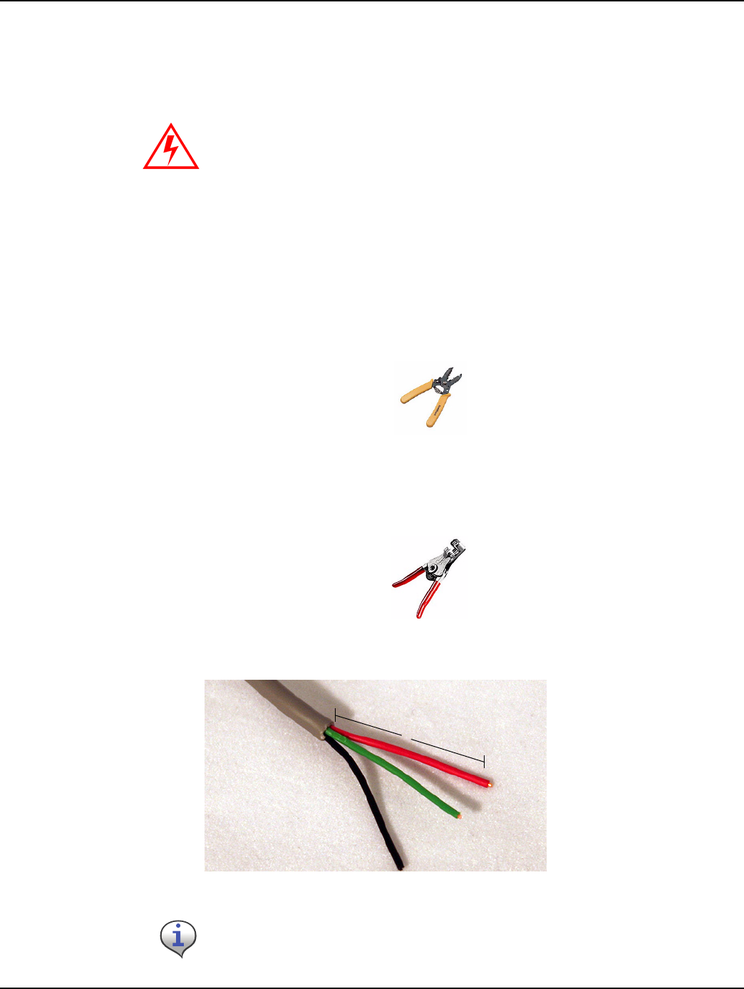
bUsingthe#10AWGposition(secondlargesthole)onthe64‐1919wirestripper,remove1
inchoftheexternalinsulationfromthecablecomingfromtheencoderregister.Donotstrip
theinsulationfromtheinternalwires.
Figure 2 - 6. 64-1919 Wire Stripper
c Peelbackfoil,ifpresent;cutexcessfoilanduninsulatedwire.
Figure 2 - 7. 3-Wire cable
Do not open a potted encoder for any reason. This will void the manufacturer’s
warranty.
Take care not to damage the internal wire insulation when removing the external insulation.
1”
Chapter 2 - Installing the Cellnet Water Endpoint Landis+Gyr
12 98-1552 CWE 6060 Remote Installation Guide
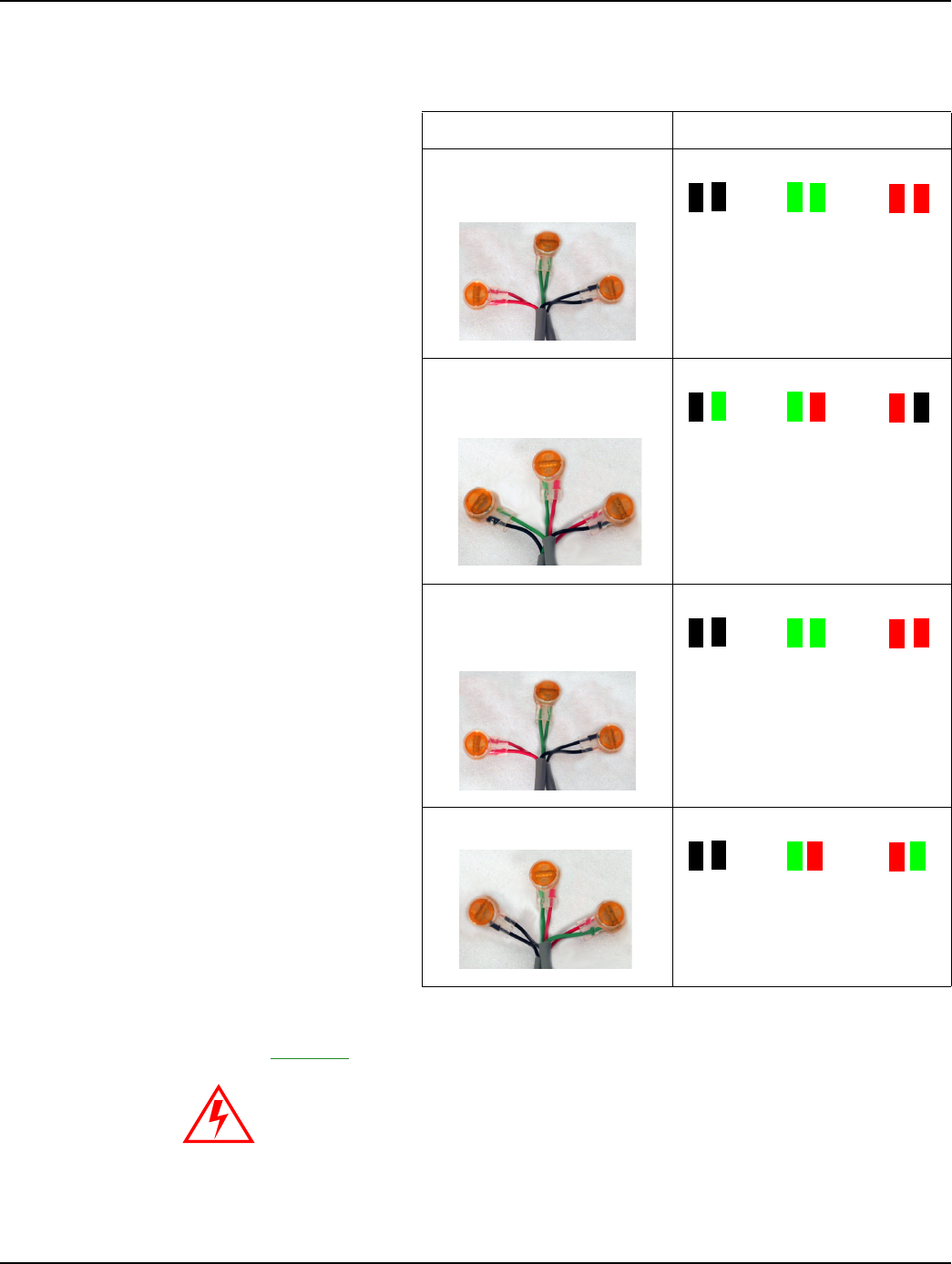
3SplicethewiresfromtheCWEtotheencoderwires.Matchcolorscarefullyaccordingtothe
tablebelow:
3SeeAppendixA,CrimpingWires,forinstructionsoncrimpingthewires.
4 ProceedtoChapter 3,TestingtheEndpoint.
Table 2-1. Wire Matching
Encoder Register 6060 Wire Color/Encoder Terminal
BadgerADE®Blk/Blk Green/Green Red/
Red
NeptuneProRead(ARB
VI)
Blk/Grn Green/Red Red/Blk
SensusECR‐II,ECR‐III
(ICE)
Blk/Blk Green/Green Red/
Red
AMCOScancoder Blk/Blk Green/Red Red/
Green
Do not open a potted encoder for any reason. This will void the manufacturer’s
warranty.
Landis+Gyr Chapter 2 - Installing the Cellnet Water Endpoint
CWE 6060 Remote Installation Guide 98-1552 13
UPro-Read Encoder Register
Before removing the ProRead receptacle, ensure that the ProRead register is programmed for three-
wire mode.
• If a two-wire conductor cable is connected to a “potted” ProRead encoder register, replace the
register with a three-wire register.
Reprogramming a ProRead encoder from 2-wire to 3-wire
It may sometimes be necessary to reprogram a ProRead register encoder from 2-wire to 3-wire
mode. Accomplish this with a Neptune ProRead field programmer.
A basic overview of the steps is as follows:
1 Connecttotheremotereceptaclewiththefieldprogrammer.
2 Interrogatetheencoderregistertodetermineitsoperatingmode(2or3‐wire).
3 Reconfiguretheencoderregistertomakeitoperatein3‐wiremodel.
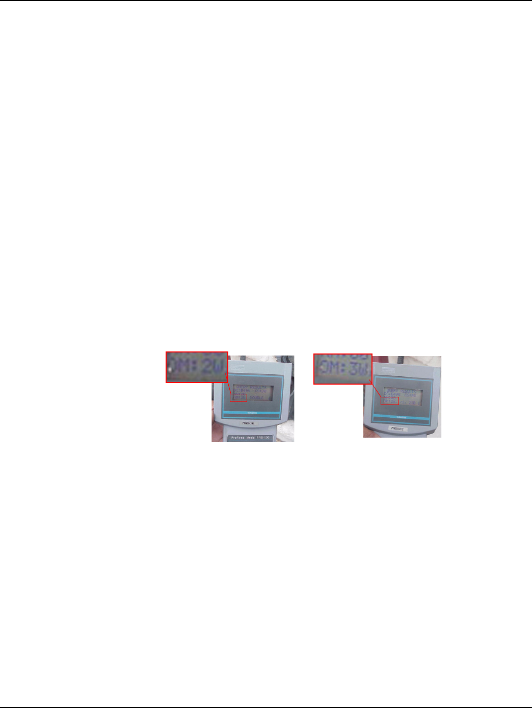
4VerifythatthereconfigurationwassuccessfulbylookingattheFieldProgrammerscreen.The
OMfieldshouldbe3W(seebelow).
Table 2-1. ProRead Encoder Images
If the register has screw terminals, proceed to "Connecting a Neptune Auto, Sensus Encoder, or
AMCO Scancoder Register with Screw Terminals" on page -8.
If the register has potted leads, proceed to "Connecting a Badger, Neptune Auto, Sensus Encoder, or
AMCO Scancoder Register with Potted Leads" on page -11.
Before Reprogramming
(2-wire mode)
After Reprogramming
(3-wire mode)
Notes:
14 CWE 6060 Remote Installation Guide
Installing the Cellnet Water Endpoint
3
CWE 6060 Remote Installation Guide 98-1551 15
Testing the Endpoint
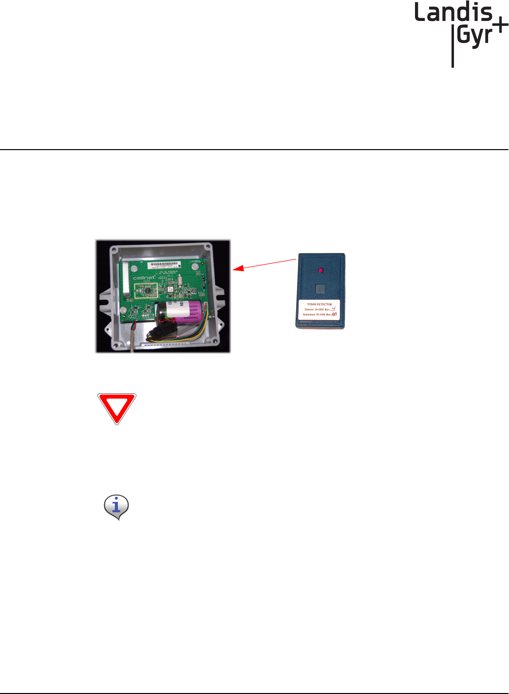
After you have completed the installation process, test the installation by passing an RF Buster
magnet near the endpoint’s sensor. The CWE tests the connection to the register and transmits a
pattern to indicate if the installation is good or bad. The RF Buster detects the transmission pattern,
beeps and lights the LED.
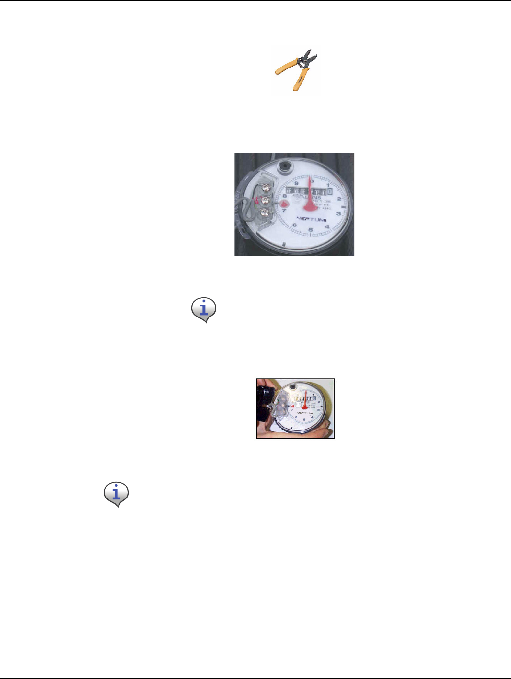
1 ActivatetheCWEbypassingtheRFBustermagnetagainstthesideoftheCWEhousingasthe
arrowindicates.
Figure 3 - 1. CWE Activation Using RF Buster
2PressandholdthebuttonontheRFBuster.PositiontheRFBusterlessthan6inchesawayfrom
thefrontoftheCWE.TheRFBustermakesaudiblebeepsandtheLEDflashestoconfirm
transmissionofanRFpacketfromtheendpoint.
3IftheRFBusterdetects6‐10packetswithin1minute,theinstallationisgoodandtheendpoint
hasbeenactivatedproperly.IftheRFBusterdetects3orfewerpackets,itindicatesabad
connectionbetweentheendpointandtheregister,abadregister,abadendpoint,oranincorrect
configuration.Iftheproblempersists,refertoTroubleshooting.
4 Attachthecoverusingthefourscrewsincludedinthehardwarekit.
5Cleantheareaandremovealldisposablematerials.
Caution: If you hold the RF Buster magnet near the side of the CWE for more than 2
seconds, it will not transmit the installation test pattern. If you do not hear beeps, hold the
RF Buster away from the CWE for 15 seconds to allow it to reset to normal operating mode.
Do not use a cell phone or any other RF device while conducting this test.
RFBuster
magnet
Notes:
16 CWE 6060 Remote Installation Guide
Testing the Endpoint

4
CWE 6060 Remote Installation Guide 98-1551 17
Endpoint Replacement
Use the HandHeld and Cellnet Remote Water Endpoint Programming Cable to deactivate all CWEs
prior to leaving the worksite. The handheld prompts you to deactivate while processing the work
order.
1OpenthefaceoftheCWERemote.
2Writedownthecolortranslation.
3Carefullycutanytiewraps.
4CutoffScotchloksnearthecrimp.
5 UnmounttheCWERemote.
Refer to "Identifying the Register for Installation" on page -7.
Notes:
18 CWE 6060 Remote Installation Guide
Endpoint Replacement

5
CWE 6060 Remote Installation Guide 98-1551 19
Troubleshooting
What if the register is not compatible with the CWE?
Verify that the register is one of the following:
•Badger ADE
®
• Neptune ProRead (ARB VI)
• Sensus ECR-II
• Sensus ECR-III
• AMCO Scancoder
If the register is not one of the models listed above, replace with a supported register type and/or the
appropriate meter.
What if the RF Buster does not beep when testing the installation?
Does the RF Buster beep and light the LED when the switch is initially pressed? if not, the battery in
the RF Buster is dead. Replace the RF Buster battery, or use another RF Buster.
Be careful not to hold the RF Buster magnet near the CWE magnet sensor on the right of the
enclosure for more than 1 second.
After activating the magnetic switch on the CWE, hold the RF Buster switch on continuously. Point
the LED end of the RF Buster toward the front of the CWE. Hold the RF Buster between 6” and 12”
from the front of the CWE. Wait 10 seconds. If the RF Buster does not beep, replace the CWE.
What if the RF Buster does not beep more than 6 times when testing the
installation?
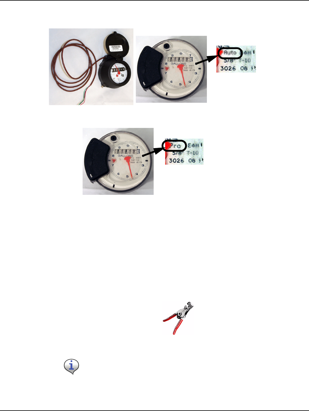
For Neptune registers, if the register is labeled “Pro”, double-check that it is configured for 3-wire
mode as instructed on "Reprogramming a ProRead encoder from 2-wire to 3-wire" on page -13. Re-
check the manufacturer and model of the register that you are installing. Make sure you have used
the correct color code for that register.
Check the wire between the CWE and the register for cuts, nicks, or broken wires. Repair or replace
the cable if necessary.
If you are using a Pro-read encoder, make sure it is programmed for 3-wire mode.
If the CWE still does not transmit more than 6 times, replace it.

Chapter 5 - Troubleshooting Landis+Gyr
20 98-1551 CWE 6060 Remote Installation Guide
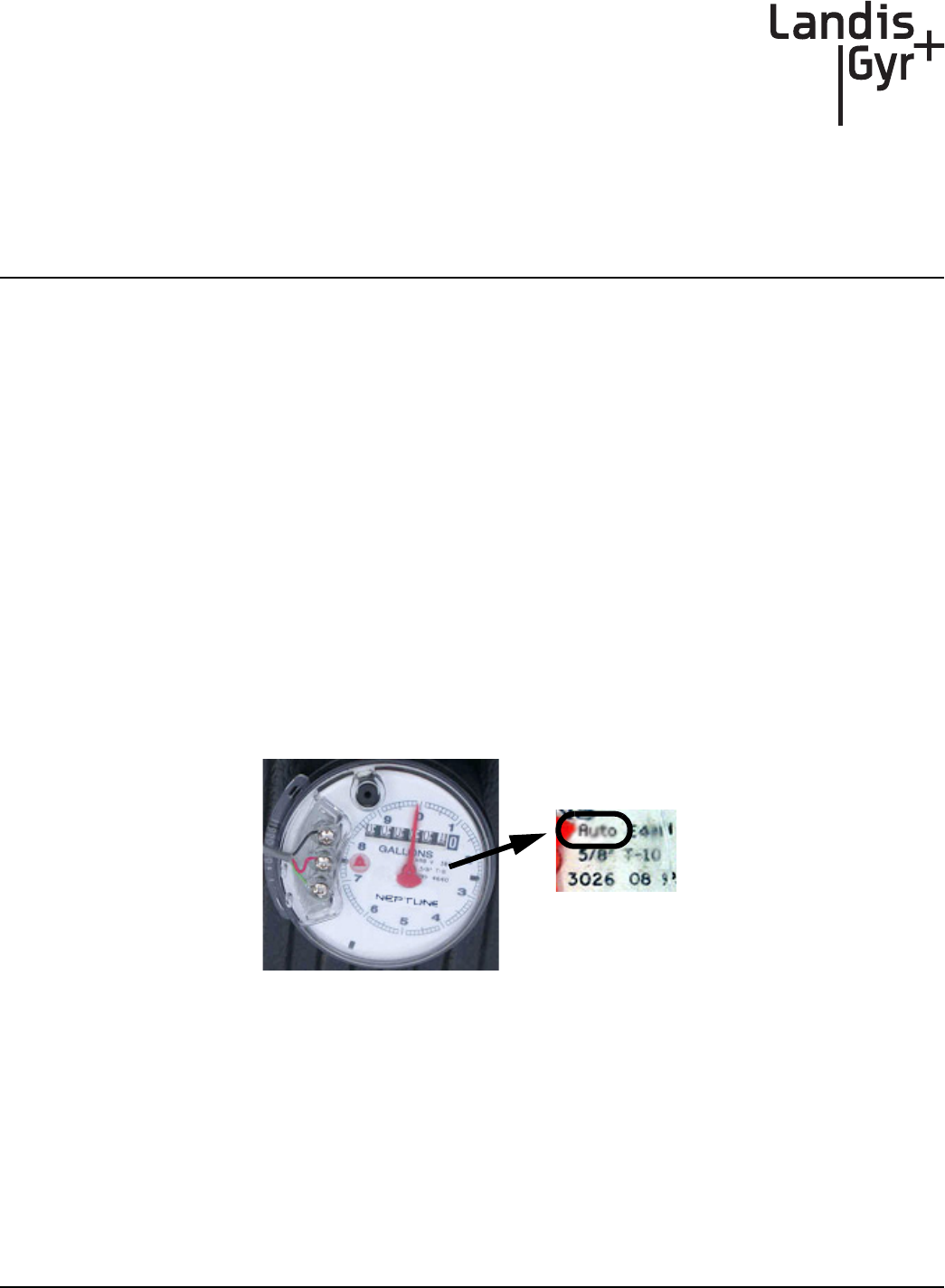
How can I tell the difference between a Sensus ECR-I and ECR-II encoder
register?
The easiest way to determine the difference between ECRI and ECRII is physical appearance. ECRI
is a “high top” design with odometer wheels behind a a flange. If you still cannot determine which
encoder register it is, please contact your local Sensus Meter Representative.
Customer Support
To reach Customer Support at Landis+Gyr:
Email: solutionsupport.na@landisgyr.com
Telephone: 1-800-791-2567.
Hours of operation - 8:00 a.m. ET to 5:00 p.m. ET
A
CWE 6060 Remote Installation Guide 98-1551 21
Crimping Wires
Use this process to crimp wires for the Cellnet Water Endpoint.
Crimping Wires
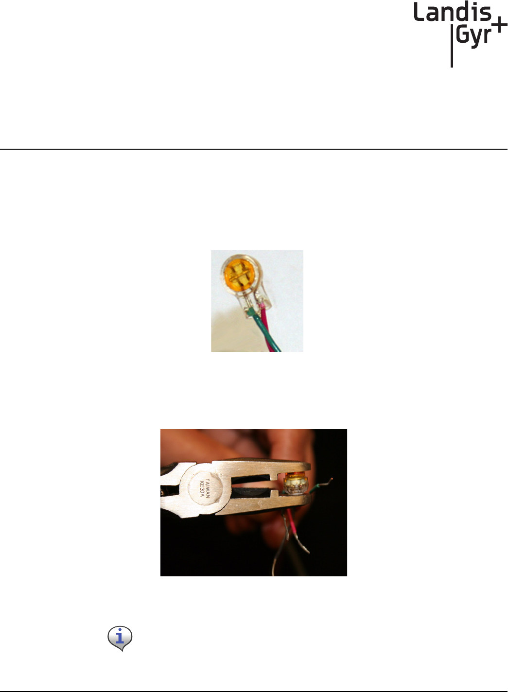
1StripthewiresthataretobeconnectedandpushthestrippedwiresintotheScotchlokconnector
asfaraspossible.
Figure A - 1. Stripped wires pushed into Scotchlok connector
2PlacetheScotchlokconnector(withwires)intothejawsofthecrimpingtool.
Figure A - 2. ScotchLok connector in crimping tool jaws
Always use 3M Parallel Jaw Crimping Tool 3M Model E-9Y or equivalent.
Appendix A - Crimping Wires Landis+Gyr
22 98-1551 CWE 6060 Remote Installation Guide
3CrimptheScotchlokconnectorbysqueezingthecrimpingtoolhandlesuntilitdischargesgel.
Continuetoapplypressurefornolessthanthreeseconds.
Figure A - 3. Crimped Scotchloks discharge gel
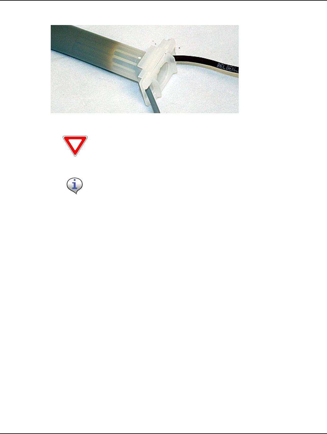
4Installthetwoplasticcabletiesonthejacketsofthesplicedwiresandtightenthecableties
securelyforstrainrelief.Removeexcesscabletiewithwirecutters.
Figure A - 4. Placing plastic ties on cables
Landis+Gyr Appendix A - Crimping Wires
CWE 6060 Remote Installation Guide 98-1551 23
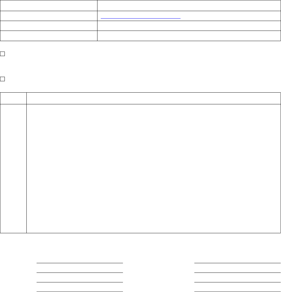
5ForspliceconnectionsoutsidetheCWERemoteenclosure,inserttheentirespliceassemblyinto
thesilicone‐filledspliceenclosure.Closethecoverandpositiontheleadstoexitalternatesides
Figure A - 5. Inserting splice assembly into silicone-filled splice enclosure
Cellnet strongly recommends a splice enclosure. Failure to use a splice enclosure
may invalidate the manufacturer’s warranty.
The 3M Gel splice connector is NOT reusable. Replace the splice if necessary.
Notes:
24 CWE 6060 Remote Installation Guide
Crimping Wires

CWE 6060 Remote Installation Guide 98-1551 25
ADE Absolute Digital Encoder
Concentrator Collects all information provided by the Cellnet endpoints.
CWE Cellnet Water Endpoint
CWE 6060 Remote Cellnet manufactured water endpoint (CWE) - available for remote,
above-ground installation
MIU Meter Interface Unit
Potted terminal Terminal with integrated, water submersible, reusable connector
PowerLAN Unique endpoint addresses
Register Device used for registering water usage. This can be an Encoder device
RF Radio Frequency
RF Buster Device used to verify RF transmission from endpoint
Screw terminal Terminal with stripped and retained leads
Glossary
Glossary
26 CWE 6060 Remote Installation Guide
Notes:


Index Landis+Gyr
28 98-1551 CWE 6060 Remote Installation Guide
Reader’s Comment Form
CellnetWaterEndpoint6060RemoteInstallationGuide(98‐1552)
Pleaseusethisformonlytoidentifypublicationerrorsortorequestchangesinpublications.Your
commentsassistusinimprovingourpublications.Directanyrequestsforadditionalpublications,
technicalquestionsaboutsystems,changesinsupport,andsoon,toyourLandis+Gyrsalesrepresentative.
Pleaseusethisformtocommunicateyourcommentsaboutthispublication,itsorganization,orsubject
matter,withtheunderstandingthatwemayuseordistributewhateverinformationyousupplyinany
waywebelieveappropriatewithoutincurringanyobligationtoyou.
Youcansendyourcommentsviaemail,conventionalmail,orfax.Thankyouforyourtimeandyourhelp.
Ifyourcommentdoesnotneedareply(forexample,pointingoutatypingerror),checkthisboxand
donotincludeyournameandaddressbelow.Ifyourcommentisapplicable,wewillincludeitinthe
nextrevisionofthemanual.
Ifyouwouldlikeareply,checkthisbox.Besuretoprintyournameandaddressbelow.
(Pleaseprint.)
To send your comments via... Use this contact information...
bã~áä ëçäìíáçåëìééçêíKå~]ä~åÇáëÖóêKÅçã
`çåîÉåíáçå~ä=ã~áä i~åÇáëHdóêI=PMMMM=jáää=`êÉÉâ=^îÉKI=pìáíÉ=NMMI=^äéÜ~êÉíí~I=d^=PMMOO
c~ñ ESTUF=ORUJNRRM
Page Comments
Date CompanyName
YourName MailingAddress
PhoneNo.
Email

cçäÇ=eÉêÉ
cçäÇ=eÉêÉ
Landis+Gyr
Attn.:TechnicalDocumentation
30000MillCreekAve.
Suite100
Alpharetta,GA30022