Larcan MXI1503U Television Broadcast Translator User Manual Operations and maintenance
Larcan Inc Television Broadcast Translator Operations and maintenance
Larcan >
Contents
- 1. user manual general info
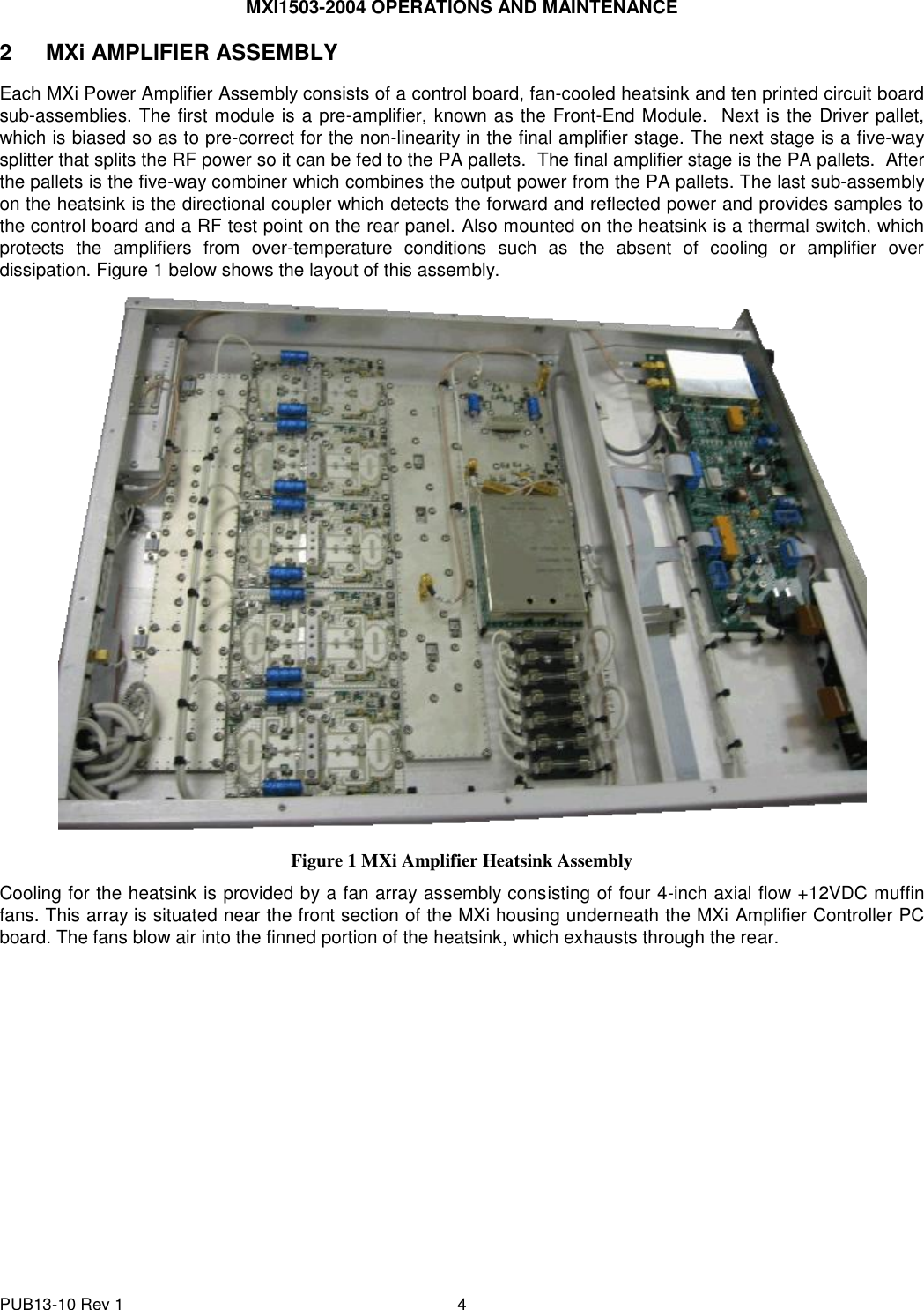
- 2. Power Amplifier
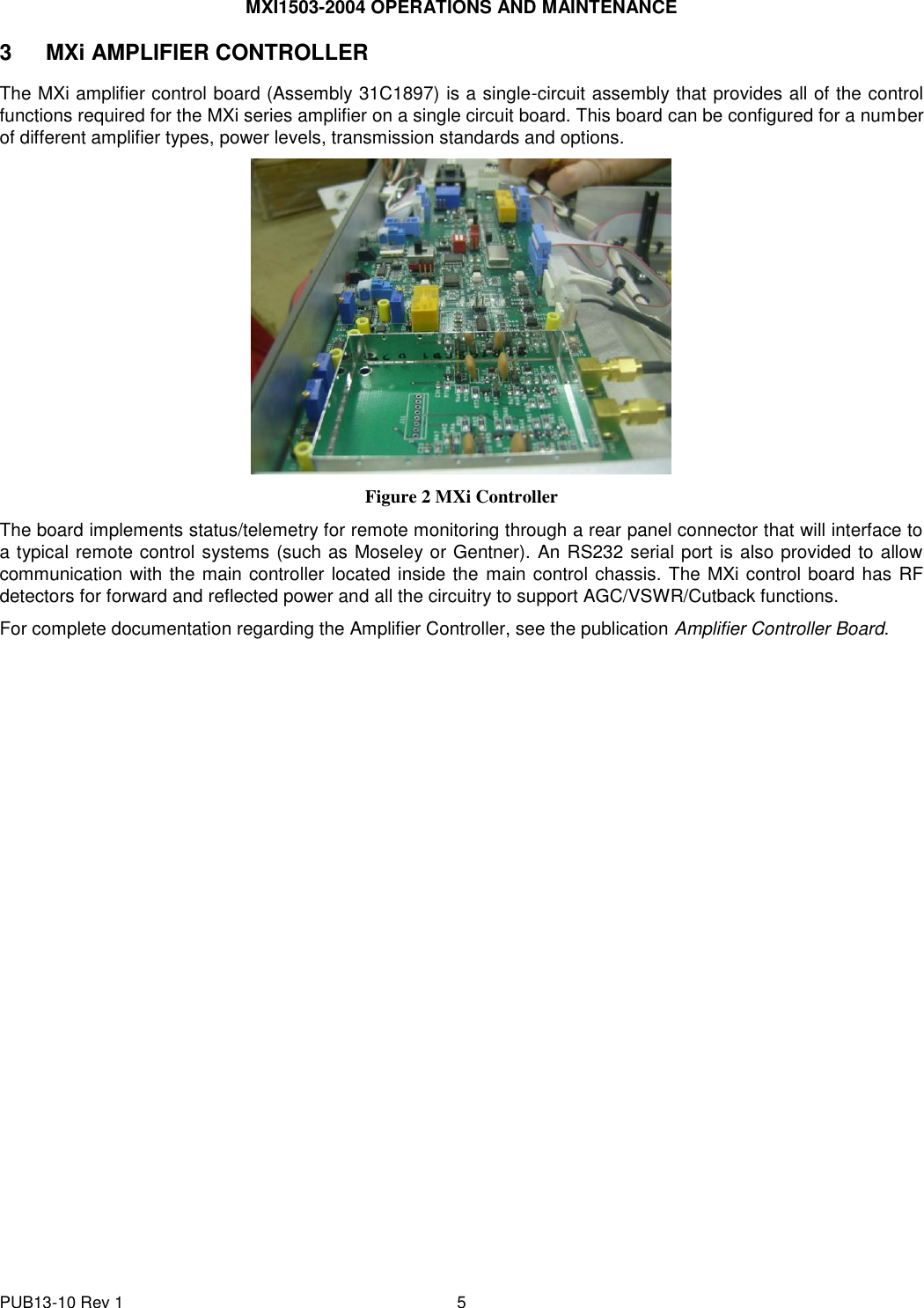
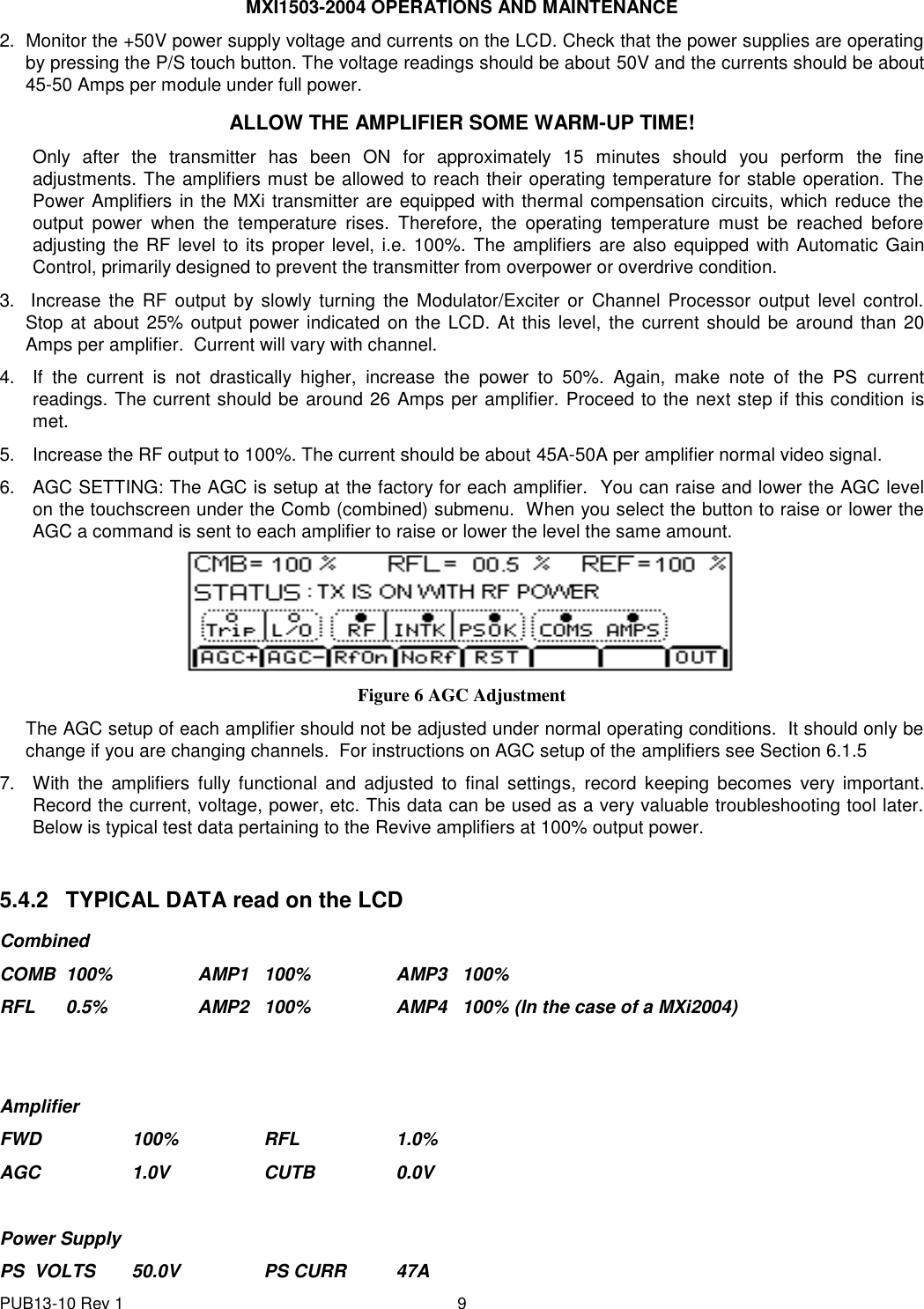
- 3. Amplifier control
- 4. splitter
- 5. control chassis
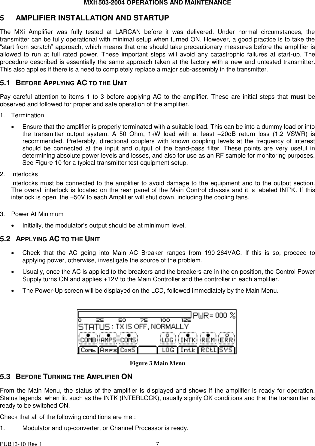
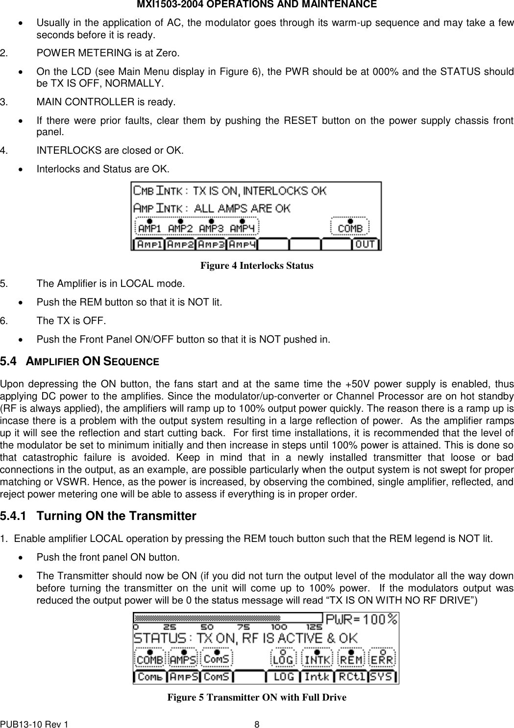
- 6. Operations and maintenance
Operations and maintenance