Leica Geosystems CPD 3DDISTO Leica 3D Disto User Manual 3D Disto UserMan
Leica Geosystems AG, CPD Leica 3D Disto 3D Disto UserMan
UserManual.wiki
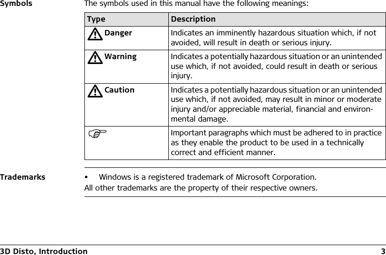
>
Leica Geosystems CPD
>
3DDISTO User Manual
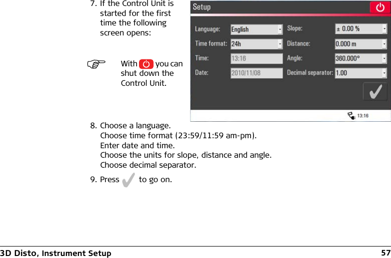
3D Disto UserMan
Navigation menu
Upload a User Manual
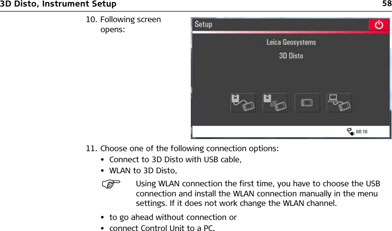
Namespaces
Wiki Guide
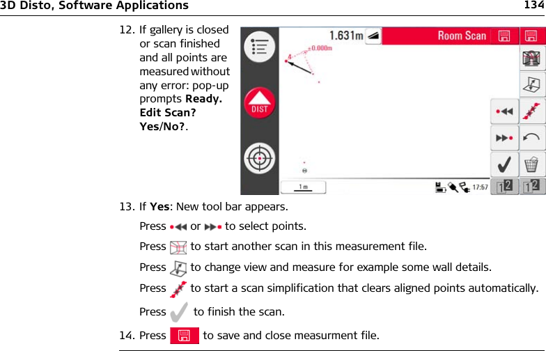
HTML
PDF
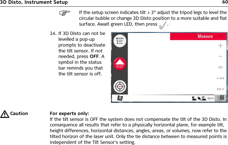
Info
Views
User Manual
Discussion / Help
Navigation
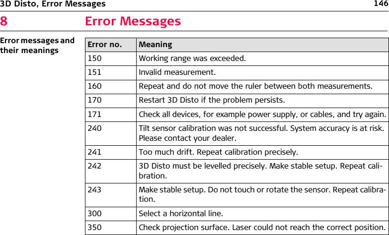
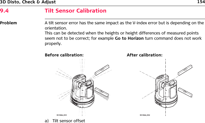
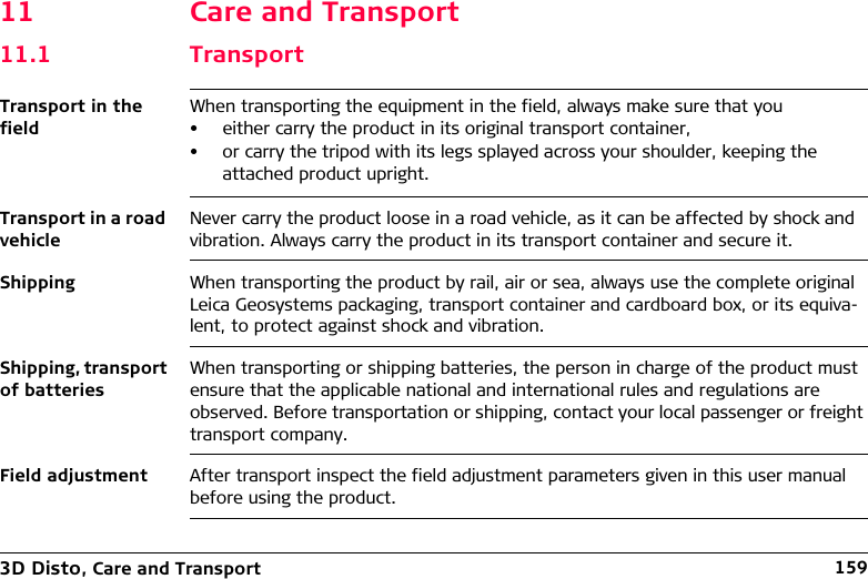
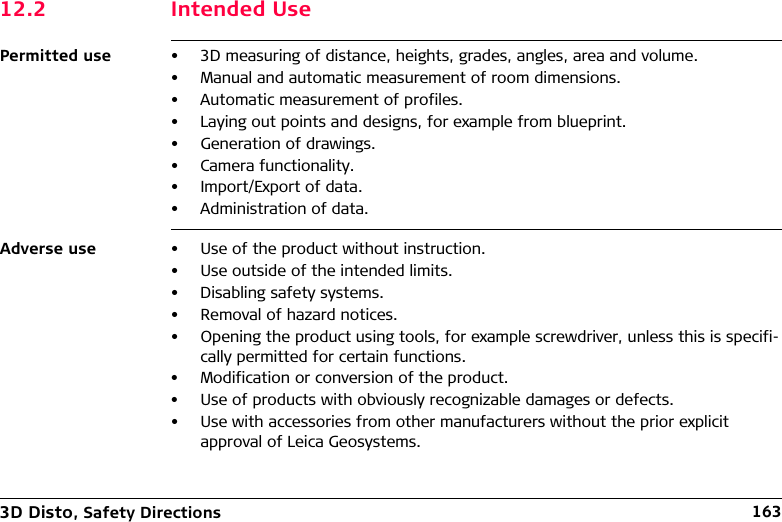
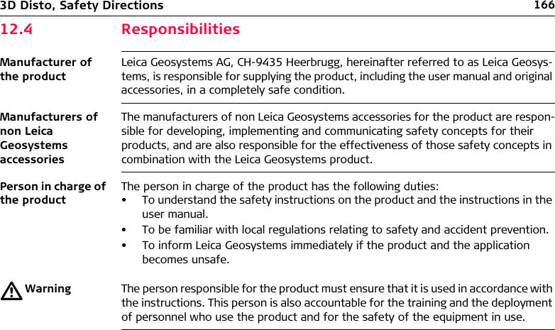
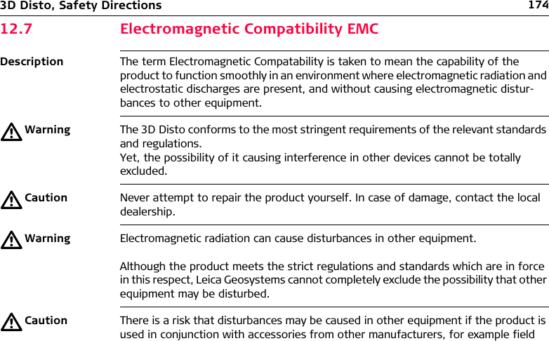
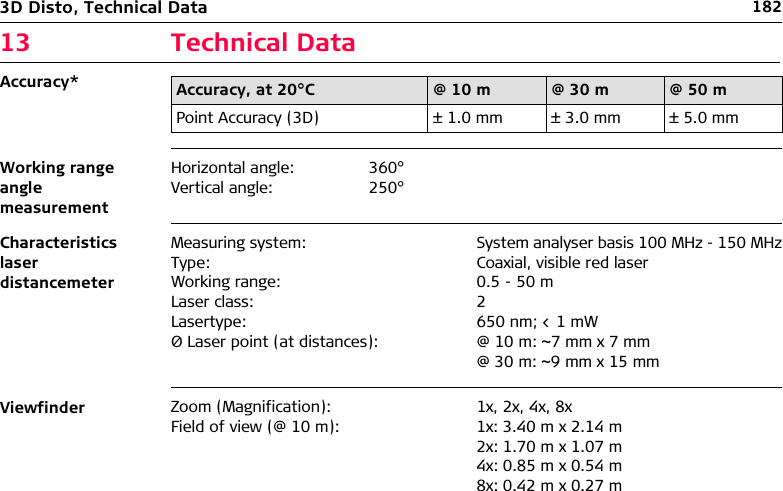
![3D Disto, Technical Terms and Abbreviations 132 Technical Terms and AbbreviationsLine of sightHorizontal anglea) Line of sightb) Tilting axis, horizontal rotation axis of the instrumentc) Standing axis, vertical rotation axis of the instrumentLine of sight, laser beam and crosshair must be congruent. Refer to "9 Check & Adjust" for more information.3D Disto_013abca) Horizontal angle, in [°] or [gon]a3D Disto_015](https://usermanual.wiki/Leica-Geosystems-CPD/3DDISTO/User-Guide-1414396-Page-13.png)
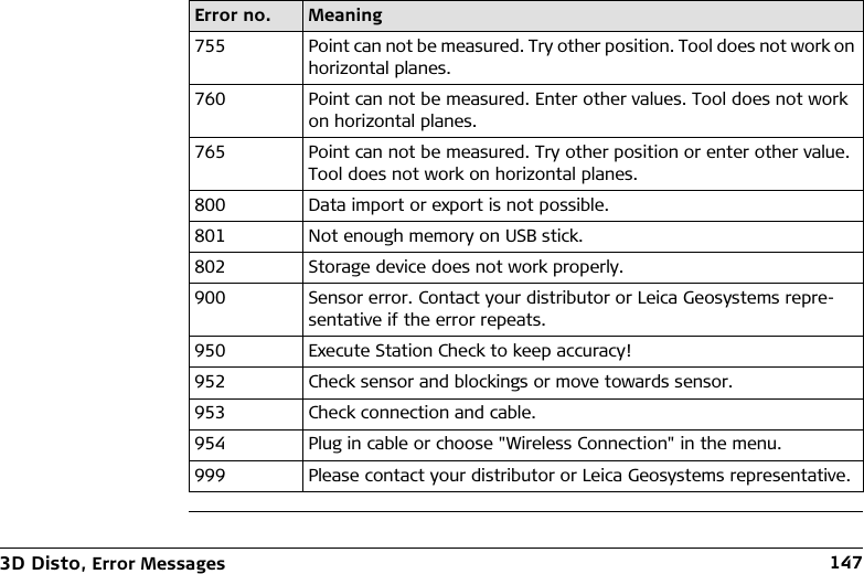
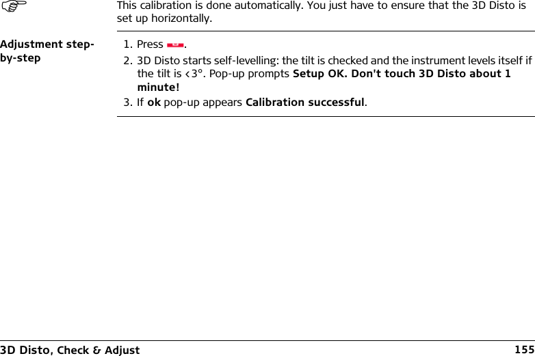
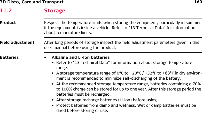
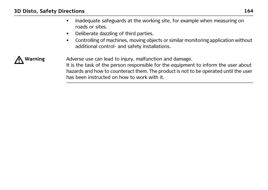
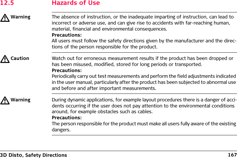
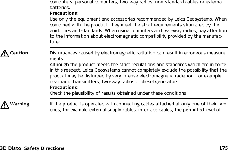
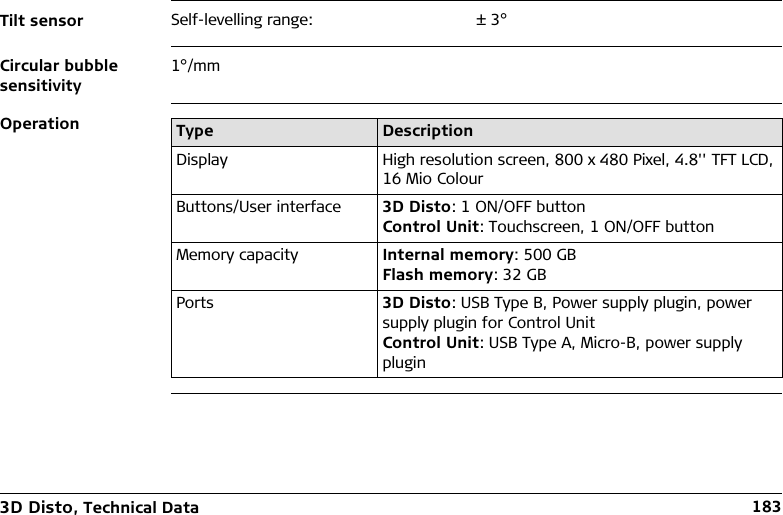
![143D Disto, Technical Terms and AbbreviationsVertical angleSetting: Horizon = 0a) Vertical angle, in [°], [gon], [1:n] or [%]Setting: Horizon = 90° / 100gona) Vertical angle, in [°] or [gon]3D Disto_016a3D Disto_017a](https://usermanual.wiki/Leica-Geosystems-CPD/3DDISTO/User-Guide-1414396-Page-14.png)

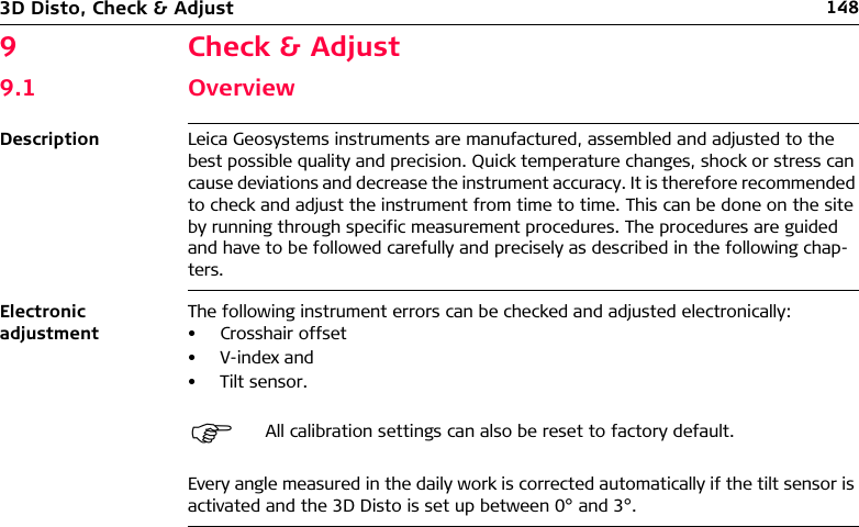
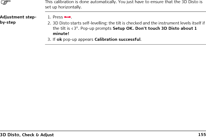
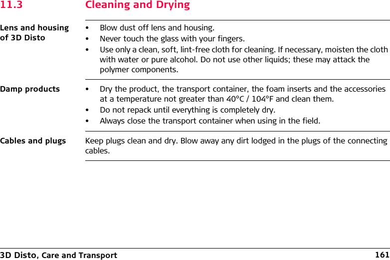
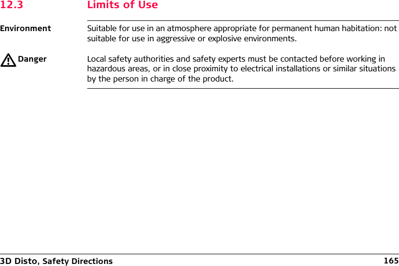
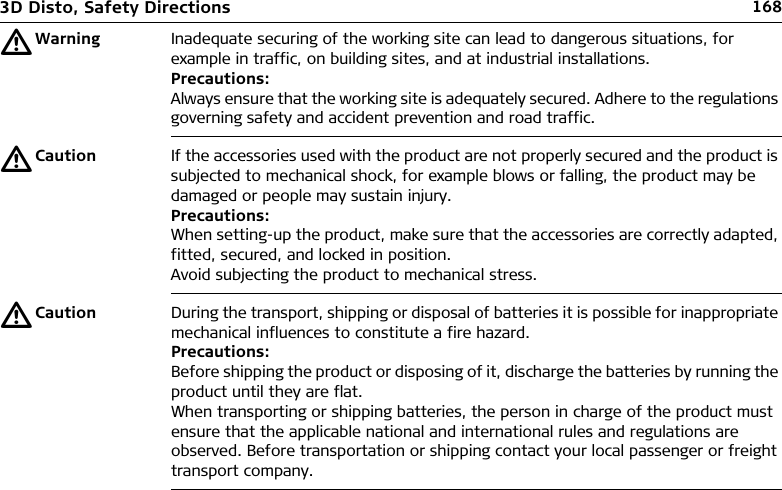
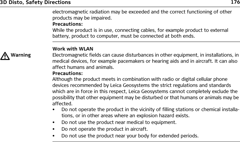
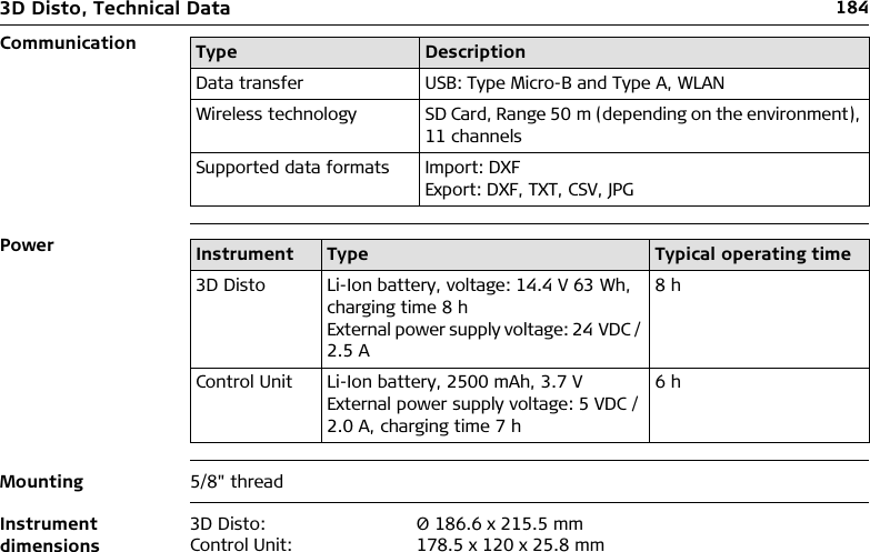
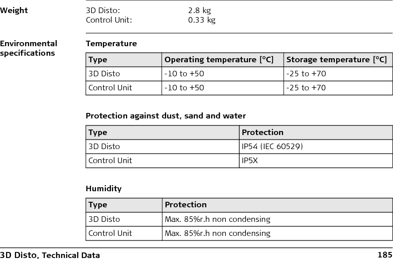
![3D Disto, Technical Data 185WeightEnvironmental specificationsTemperatureProtection against dust, sand and waterHumidity3D Disto: 2.8 kgControl Unit: 0.33 kgType Operating temperature [°C] Storage temperature [°C]3D Disto -10 to +50 -25 to +70Control Unit -10 to +50 -25 to +70Type Protection3D Disto IP54 (IEC 60529)Control Unit IP5XType Protection3D Disto Max. 85%r.h non condensingControl Unit Max. 85%r.h non condensing](https://usermanual.wiki/Leica-Geosystems-CPD/3DDISTO/User-Guide-1414396-Page-185.png)