Leica Geosystems CPD 3DDISTO Leica 3D Disto User Manual 3D Disto UserMan
Leica Geosystems AG, CPD Leica 3D Disto 3D Disto UserMan
3D Disto UserMan

Leica 3D Disto
User Manual
Version 0.9
English
2
3D Disto, Introduction
Introduction
Purchase Congratulations on the purchase of a Leica 3D Disto.
This manual contains important safety directions as well as instructions for setting
up the product and operating it. Refer to "12 Safety Directions" for further informa-
tion.
Read carefully through the User Manual before you switch on the product.
Product
identification
The serial number of your product is indicated on the data label, refer to "12.8 FCC
Statement, Applicable in U.S.". Enter the serial number in your manual and always
refer to this information when you need to contact your authorised dealer or to
register in the Leica MyWorld portal.
Serial No.: _______________
3D Disto, Introduction 3
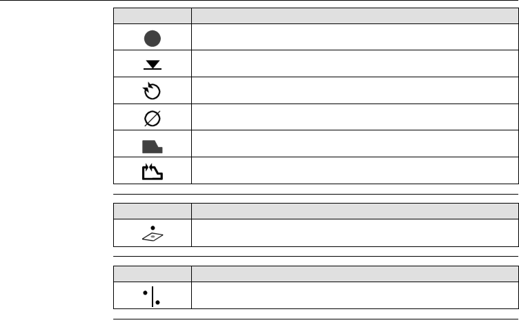
Symbols The symbols used in this manual have the following meanings:
Trademarks • Windows is a registered trademark of Microsoft Corporation.
All other trademarks are the property of their respective owners.
Type Description
ƽDanger Indicates an imminently hazardous situation which, if not
avoided, will result in death or serious injury.
ƽWarning Indicates a potentially hazardous situation or an unintended
use which, if not avoided, could result in death or serious
injury.
ƽCaution Indicates a potentially hazardous situation or an unintended
use which, if not avoided, may result in minor or moderate
injury and/or appreciable material, financial and environ-
mental damage.
Important paragraphs which must be adhered to in practice
as they enable the product to be used in a technically
correct and efficient manner.

4
3D Disto, Table of Contents
Table of Contents
In this manual Chapter Page
1 How to Use this Manual 9
2 Technical Terms and Abbreviations 13
3 Description of the System 25
3.1 General 3D Disto System Information 25
3.2 Container Contents 26
3.3 Instrument Components 28
3.3.1 3D Disto 28
3.3.2 Control Unit 32
3.3.3 RM100 Remote Control 33
3.4 Power Supply 34
3.4.1 3D Disto 34
3.4.2 Control Unit 35
3.4.3 RM100 Remote Control 37
3.5 Software Concept 38
4 User Interface 44
4.1 Control Unit 44
4.1.1 Screen 45

3D Disto, Table of Contents 5
4.1.2 Main Operation Bar 48
4.1.3 Tool Bar 49
4.1.4 Icons & Symbols 50
4.2 RM100 Remote Control 53
5 Instrument Setup 54
5.1 Startup Procedure 54
5.2 Assistant 62
5.3 Device Configuration and Menu Settings 64
5.4 Data Management 67
5.4.1 General 67
5.4.2 File Manager 69
5.4.3 Photo and Secure Points Administration 71
5.4.4 Data Transfer 73
5.5 Calculator 79
6 Operation 81
6.1 Measurements 81
6.2 Viewfinder 82
6.3 Measurement Workflow 87
6.4 Touch Screen in Sketch Area 92
6.5 Addition and Subtraction 94
6.6 Area & Volume Calculations 97
6.6.1 Horizontal Areas/Volumes 98

6
3D Disto, Table of Contents
6.6.2 Tilted Areas 100
7 Software Applications 101
7.1 Overview 101
7.2 Tool Kit 102
7.2.1 Comfort Plumbing 103
7.2.2 Comfort Targeting 105
7.2.3 Comfort Level 107
7.2.4 Meter Mark 109
7.2.5 Height Tracking 111
7.2.6 Parallel Line 113
7.3 Location 115
7.4 Room Scan 121
7.4.1 Manual Measurement 123
7.4.2 Unfold Mode 125
7.4.3 Auto Shapes 127
7.4.4 Automated Profile Room Scan 130
7.5 Projector 137
7.5.1 Workflow 138
7.5.2 Targeting and Layout with RM100 Remote Control 145

3D Disto, Table of Contents 7
8 Error Messages 146
9 Check & Adjust 148
9.1 Overview 148
9.2 Cross Hair Offset 150
9.3 V-Index Error 152
9.4 Tilt Sensor Calibration 154
9.5 Reset to Factory Settings 156
10 Instrument Protection (Theft Protection) 157
11 Care and Transport 159
11.1 Transport 159
11.2 Storage 160
11.3 Cleaning and Drying 161
12 Safety Directions 162
12.1 General 162
12.2 Intended Use 163
12.3 Limits of Use 165
12.4 Responsibilities 166
12.5 Hazards of Use 167
12.6 Laser Classification 172
12.7 Electromagnetic Compatibility EMC 174

3D Disto, How to Use this Manual 9
1 How to Use this Manual
It is recommended to setup the instrument while reading through this manual.
Index The index is at the back of the manual.
Keys, fields and options on the screens which are considered as self-explanatory are
not explained.
Validity of this
manual
This manual applies to the 3D Disto instruments and software application.
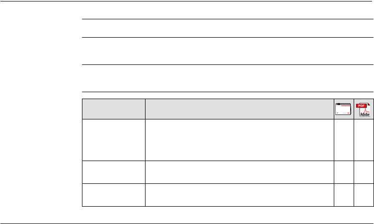
Available
documentation Name Description/Format
3D Disto User
Manual
All instructions required in order to operate the
instrument to a basic level are contained in this User
Manual. Provides an overview of the instrument
together with technical data and safety directions.
-
3D Disto Quick
Start
Intended as a quick reference field guide.
Safety Manual Provides important safety instructions for use of
3D Disto.

10
3D Disto, How to Use this Manual
Refer to the following resources for all 3D Disto documentation/software:
• the Leica 3D Disto CD
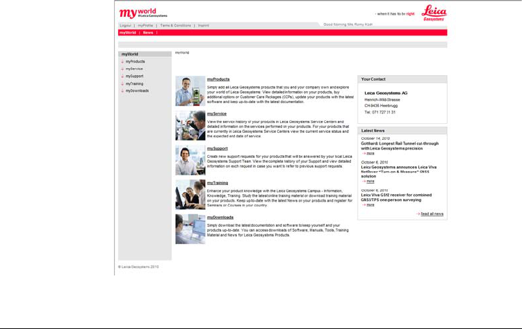
• https://myworld.leica-geosystems.com
myWorld@Leica Geosystems (https://myworld.leica-geosystems.com) offers a wide
range of services, information and training material.
With direct access to myWorld, you are able to access all relevant services whenever
it is convenient for you, 24 hours a day, 7 days per week. This increases your effi-
ciency and keeps you and your equipment instantly updated with the latest informa-
tion from Leica Geosystems.
3D Disto, How to Use this Manual 11
12
3D Disto, How to Use this Manual
Service Description
myProducts Simply add all Leica Geosystems products that you and your
company own. View detailed information on your products, buy
additional options, update your products with the latest software
and keep up-to-date with the latest documentation.
mySupport Create new support requests for your products that will be
answered by your local Leica Geosystems Support Team. View the
complete history of your Support and view detailed information on
each request in case you want to refer to previous support
requests.
myTraining Enhance your product knowledge with the Leica Geosystems
Campus - Information, Knowledge, Training. Study the latest online
training material or download training material on your products.
Keep up-to-date with the latest News on your products and
register for Seminars or Courses in your country.
3D Disto, Technical Terms and Abbreviations 13
2 Technical Terms and Abbreviations
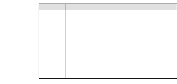
Line of sight
Horizontal angle
a) Line of sight
b) Tilting axis, horizontal rotation axis of the
instrument
c) Standing axis, vertical rotation axis of the
instrument
Line of sight, laser beam and crosshair
must be congruent. Refer to "9 Check &
Adjust" for more information.
3D Disto_013
a
b
c
a) Horizontal angle, in [°] or [gon]
a
3D Disto_015
14
3D Disto, Technical Terms and Abbreviations
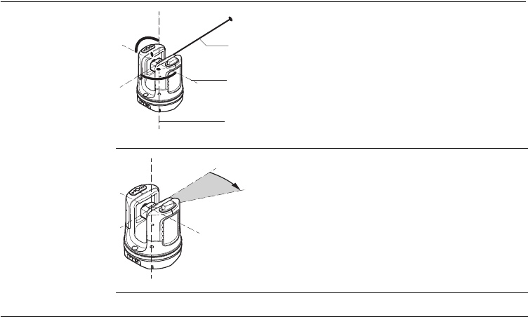
Vertical angle
Setting: Horizon = 0
a) Vertical angle, in [°], [gon], [1:n] or [%]
Setting: Horizon = 90° / 100gon
a) Vertical angle, in [°] or [gon]
3D Disto_016
a
3D Disto_017
a
3D Disto, Technical Terms and Abbreviations 15
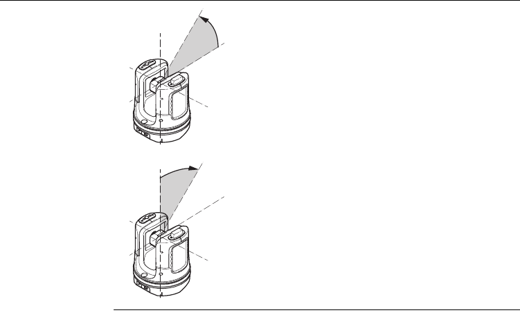
Distances
a) Orthogonal distance
a) Tie distance
b) Vertical distance = height difference
c) Horizontal distance
3D Disto_018
a
3D Disto_019
c
a
b
16
3D Disto, Technical Terms and Abbreviations
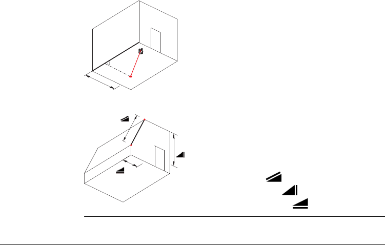
Areas
Zenith and horizon
a) Tilted area, as measured
b) Horizontal area, calculated by 3D Disto
b
a
3D Disto_020
a) Zenith:
Point on the plumb line above/below the
observer.
b) Horizon:
Plane/Line 90° to the plumb line.
3D Disto_014
a
b
3D Disto, Technical Terms and Abbreviations 17
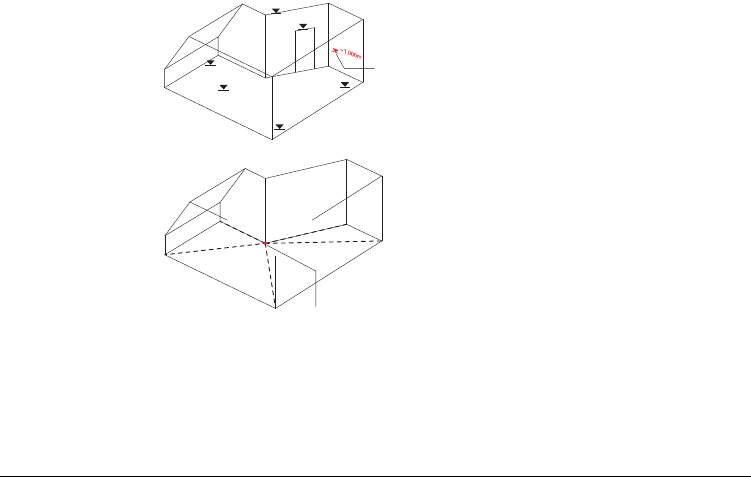
References
a) Reference height:
A level that all heights refer to.
a) Reference point:
A point that all dimensions refer to.
3D Disto_021
0.00
-0.02
0.00
0.00
+2.10
+3.00
a
3D Disto_022
4.160
5.390
3.965
5.134
1.884
a
18
3D Disto, Technical Terms and Abbreviations
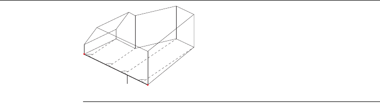
a) Reference line:
A line that all dimensions refer to.
3D Disto_023
3.101
2.911
7.040
7.002
a
3D Disto, Technical Terms and Abbreviations 19
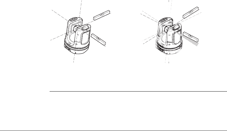
Tilt sensor The tilt sensor guarantees correct results even if you do not set up the 3D Disto
exactely horizontal.
Tilt sensor off = disabled
All measurement results relate to the
tilted axis and horizon of the 3D Disto.
Tilt sensor on = enabled
Measurement results are correctly hori-
zontal if the 3D Disto is set up between
0° and 3°.
3D Disto_024
3D Disto_025
0-3°
20
3D Disto, Technical Terms and Abbreviations
Viewfinder and
Crosshair
• The so called Viewfinder is an integrated camera which shows the target on the
Control Unit display.
•The crosshair is an aiming guide displayed on the Control Unit.
a) Viewfinder
b) Crosshair
S_3D Disto_002 a b
3D Disto, Technical Terms and Abbreviations 21
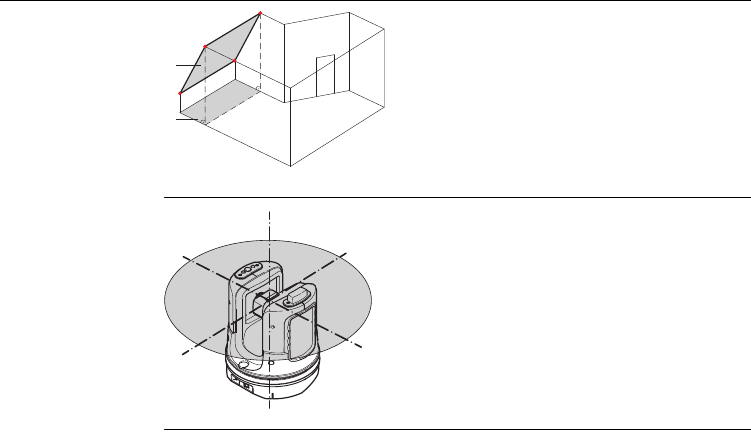
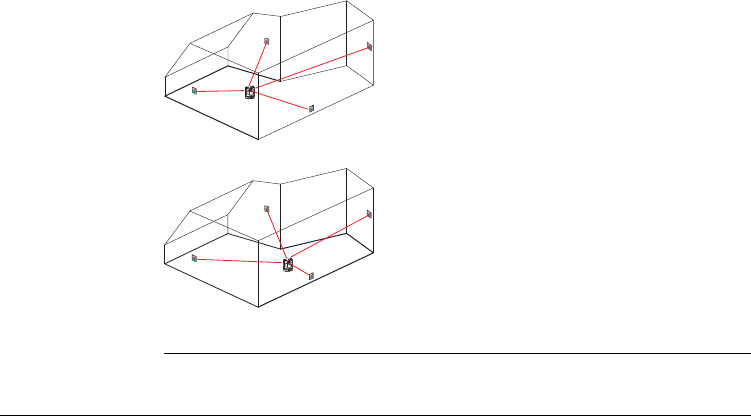
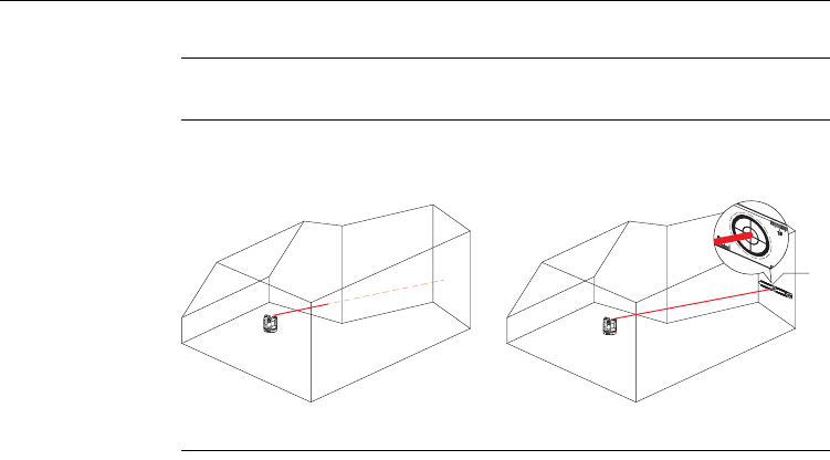
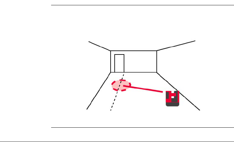
Secure Points Secure Points lock a measurement to a coordinate system. These reference
points allow to change the 3D Disto’s location or to continue a measurement at a
later time, so that all measurements fit together perfectly.
Refer to "7.3 Location" for more information.
1. Name and place three to five self-adhesive
target marks on walls, ceiling or floor around
your working area.
2. Measure these target marks and save them as
Secure Points.
3. Relocate the 3D Disto or set it up "anywhere"
at a later time.
4. Measure the Secure Points again. 3D Disto
relocates itself and measurement works can
be continued.
3D Disto_026
3D Disto_027
22
3D Disto, Technical Terms and Abbreviations
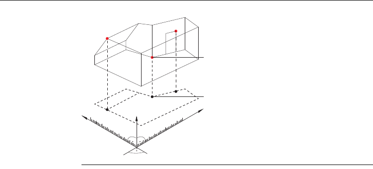
Coordinates Coordinates describe the position of a point in the two or three dimensional room.
a) Two dimensional coordinates
b) Three dimensional coordinates
3D Disto_028
b
a
m/ft
3D Disto, Technical Terms and Abbreviations 23
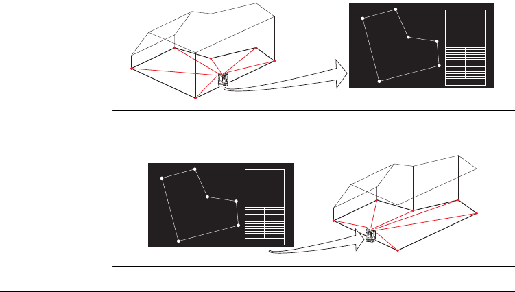
Measure Measurement results can be transferred to a connected PC or USB stick for post-
processing.
Layout or
projection
Design data in DXF format can be imported and used to lay out the according points
or grids.
3D Disto_045
CAD
3D Disto_046
CAD
24
3D Disto, Technical Terms and Abbreviations
Laser distance
meter (LDM)
The laser distance meter (LDM) allows to determine the distance by using a visible
red laser beam.
Calibration Calibration is a workflow to check and adjust the accuracy of the instrument.
Refer to "9 Check & Adjust" for more information.
Ruler for offset
points
Ruler for offset points is an accessory that allows to measure inaccessible or hidden
points.
a) Ruler for offset points
3D Disto_035
a
?
3D Disto, Description of the System 25
3 Description of the System
3.1 General 3D Disto System Information
General
information
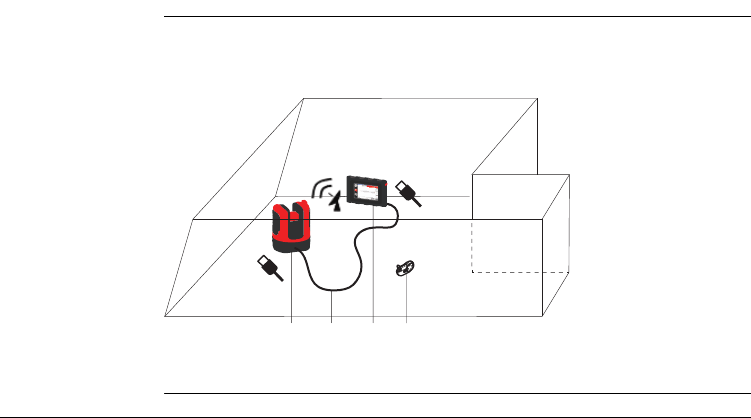
Leica Geosystems’ 3D Disto is a three dimensional measuring and projection system
that allows to measure points in a room from one setup position and generates 3D
data – ready to use or for post-processing.
3D Disto is operated via the Control Unit. Certain functions can also be managed by
the RM100 Remote Control.
a) Control Unit
b) USB cable
c) 3D Disto
d) RM100 Remote
Control
3D Disto_001 a b c d
26
3D Disto, Description of the System
3.2 Container Contents
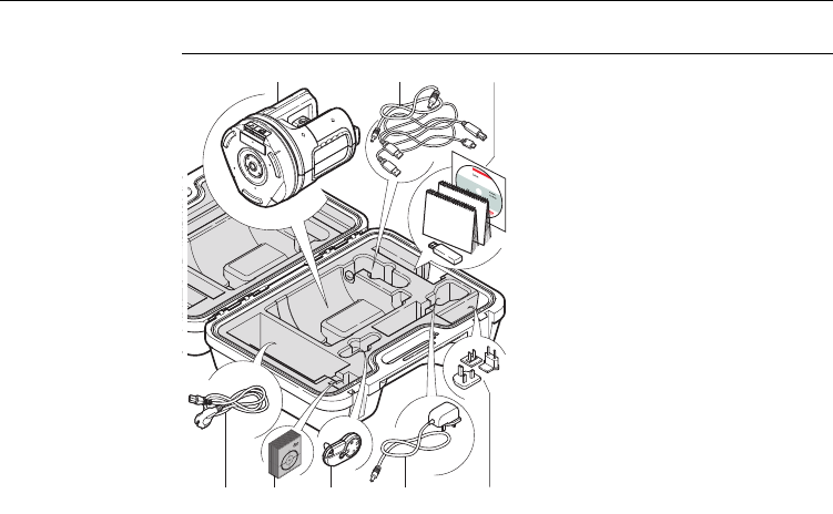
Container
contents,
part 1 of 2 a) 3D Disto with inbuilt SD WLAN Card
b) USB Connection Cable 3D Disto to
the Control Unit
Power Cable 3D Disto to the Control
Unit
Mini-USB Cable for PC
c) Data CD
Safety Instructions Manual,
3D Disto Getting Started Guide,
CE & Producer Certificate,
USB Stick
d) Four country-specific cables for
Power Supply 3D Disto
e) Target Marks, self-adhesive, 50 units
in one bag
f) RM100 Remote Control
g) Control Unit power supply
h) Country-specific adapter plug-ins for
Control Unit power supply
ab
ef g hd
c
3D Disto_002
3D Disto, Description of the System 27
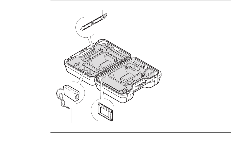
Container
contents,
part 2 of 2
i) Ruler for offset points
j) Power Supply 3D Disto
k) Control Unit with Pen,
Tripod Clamp and Hand
strap
i
j
3D Disto_003 k
28
3D Disto, Description of the System
3.3 Instrument Components
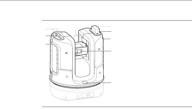
3.3.1 3D Disto
Instrument
components,
motor-driven part
a) LEDs for 3D Disto status
b) ON/OFF button
c) Trays to hold the instrument
d) Infrared (IR) interface
e) WLAN interface
f) Laser distance meter with Viewfinder
g) Circular bubble
a
c
b
d
e
f
g
3D Disto_004
c
c
3D Disto, Description of the System 29
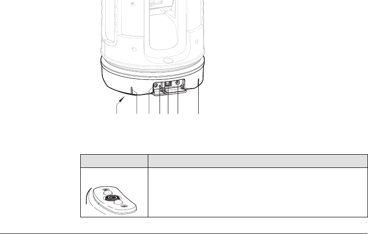
Instrument
component,
battery socket
Description of buttons and LEDs
a) Tripod thread 5/8”
b) 90° marking
c) Power supply connector for 3D Disto
d) LED for battery status
e) Data cable connector
f) Power supply connector to Control
Unit
Button/LEDs Description
ON/OFF button Button to turn instrument ON or OFF.
Instrument turns OFF after 15 minutes if not connected to the
Control Unit.
3D Disto_005 dc e f bba
30
3D Disto, Description of the System
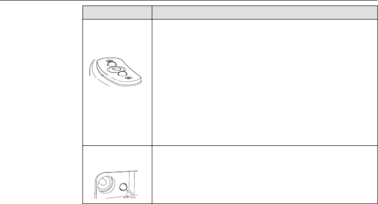
LEDs for 3D Disto
status
• Green and orange LEDs flash: If 3D Disto is turned ON.
• Orange LED flashes fast: Booting and Self-Levelling Proce-
dure is running.
• Green LED flashes slowly: tilt 3° after Self-Levelling check.
3D Disto is ready for measurement. Tilt sensor is on.
• Orange LED flashes fast: tilt >3° after Self-Levelling check.
• Green LED off, orange LED flashes continuously:
An error happened. Refer to "8 Error Messages" for more
information.
For experts only: Tilt sensor off
• Green LED flashes slowly, followed by orange LED flashing
three times while green LED is off.
LED for battery
status
If instrument is on and connected to the charger:
• Green LED 1x flashing: Battery is charged to 25 %.
• Green LED 2x flashing: Battery is charged to 50 %.
• Green LED 3x flashing: Battery is charged to 75 %.
• Green LED flashes: Battery is fully charged.
Button/LEDs Description
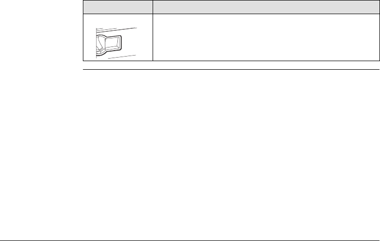
3D Disto, Description of the System 31
LDM Laser • OFF: Viewfinder is OFF or 3D Disto targets automatically.
•ON: Viewfinder is ON; user is targeting manually.
•Flashing: to indicate the precise position of a projected
point.
Button/LEDs Description
32
3D Disto, Description of the System
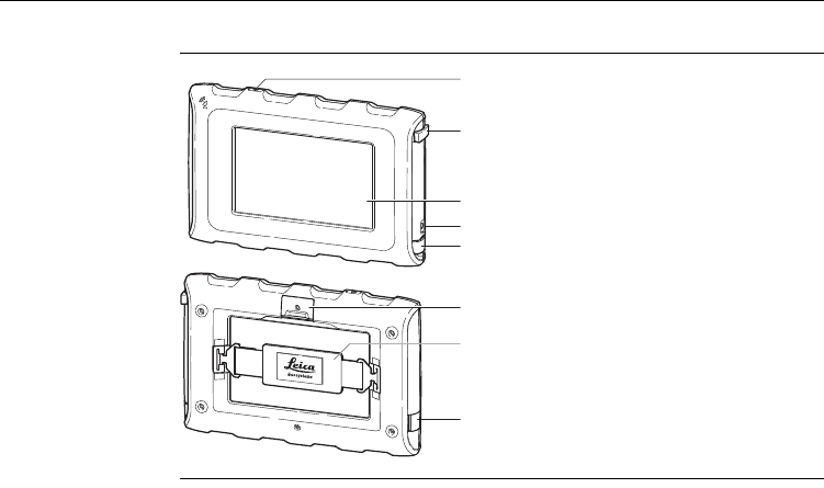
3.3.2 Control Unit
Control Unit
components
a) ON/OFF button
b) Pen
c) Display, 4.8" touch screen
d) Power supply connector
e) USB Port, Type A
f) Tripod clamp, extendable
g) Hand strap
h) Micro-USB Port, Type Micro-B
a
b
c
d
e
f
g
h
3D Disto_006
3D Disto, Description of the System 33
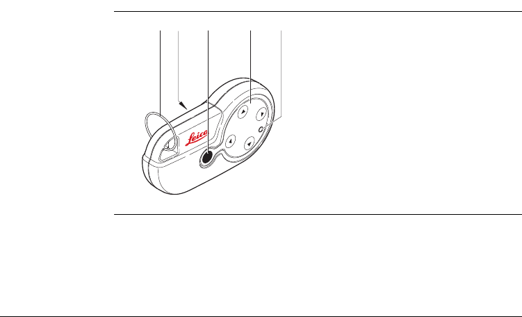
3.3.3 RM100 Remote Control
Remote Control
components
a) Key ring
b) Battery compartment
c) Distance button
d) Navigation buttons:
Up/down/right/left
e) Control LED
RM100
acbde
3D Disto_007
34
3D Disto, Description of the System
3.4 Power Supply
3.4.1 3D Disto
3D Disto power
supply
Power for the instrument can be supplied either internally or externally:
•Internal: via battery socket, with non-removable Li-Ion batteries, 14.4 V, 63 Wh.
•External:
Power supply for 3D Disto connected via cable with country-specific plugs for
worldwide use. Input: 100 - 240 V AC, 50/60 Hz, Output: 24 V DC, 2.5 A, length
1.80 m.
Only Leica Geosystems authorised service workshops are entitled to replace the
battery socket.
a) Battery socket
b) Power supply connector
a
3D Disto_008
b

3D Disto, Description of the System 35
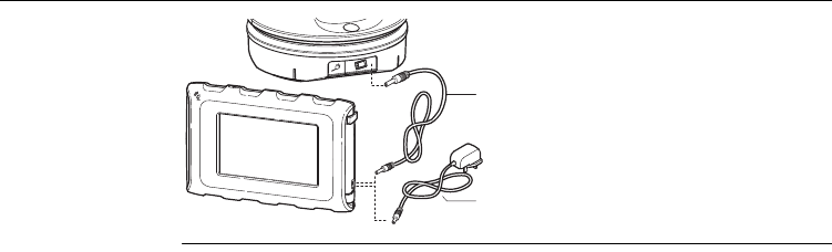
3.4.2 Control Unit
Control Unit power
supply
Power for the Control Unit can be supplied either internally or externally:
•Internal: non-removable Lithium polymer battery, 2500 mAh, 3.7 V DC.
•External:
• Power supply with AC/DC adapter. EU, US, UK and AUS adapter plug-ins avail-
able. Input: 100 - 240 V AC, 50/60 Hz, Output: 5.2 V DC, 2000 mA, cable
length 1.50 m.
• Power supply from 3D Disto via cable. >5 V, 2.5 A, length 2.00 m.
The display of the Control Unit turns off after 15 minutes to save power
during periods of inactivity.
The Control Unit powers on when plugging in the power supply adapter.
The Control Unit can only be charged if the 3D Disto is charged more
than 25%.
36
3D Disto, Description of the System
a) Power supply cable from 3D Disto
b) Power supply from mains supply with
AC/DC adapter
b
a
3D Disto_009
3D Disto, Description of the System 37
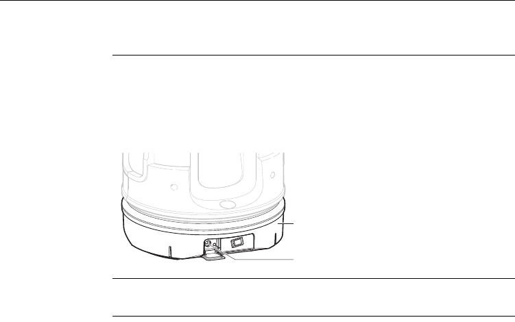
3.4.3 RM100 Remote Control
RM100 Remote
Control power
supply
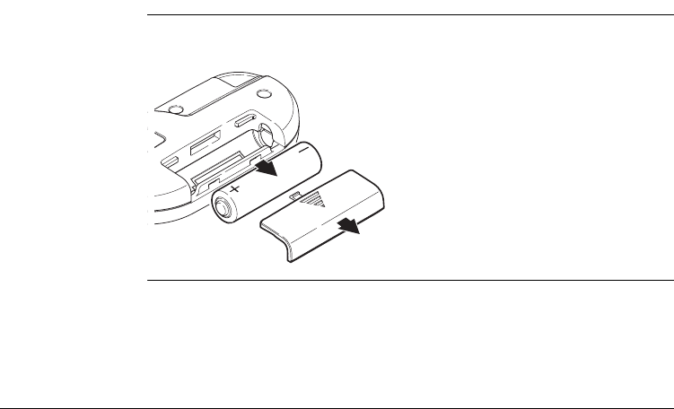
The RM100 is equipped with one AA alkaline battery, 1.5 V.
1. Push the battery cover in the direction
of the arrow to open the battery
compartment.
2. Replace the battery and refit the
battery cover.
3D Disto_010
2
1
38
3D Disto, Description of the System
3.5 Software Concept
3D Disto system
software
The 3D Disto software comprises the central functions of the instrument:
• Several languages are integrated into this software. The preferred operating
language can be chosen at the first setup or in the Setting menu.
• The instrument has a restart function in case the Control Unit is not responding.
To restart the instrument press for ten seconds.
• To reset the software to the factory settings go to Menu, press Settings and
Reset to default.
Application
programs
Several application programs are available for the instrument, supported by assistant
pop-ups that guide through the workflow. These applications can be tested in a
Demo mode or by activation through license keys.
Demo mode There is an option to test the available application programs by activating the Demo
mode first. This provides full software performance for 40 working hours. A pop-up
reminds when Demo mode runs out.
To enable the application programs in Demo mode, carry out the following steps:
1. Press Menu » Applications » Demo.
2. All application programs are listed in the Menu and marked with a sandglass
symbol until Demo mode runs out.
3D Disto, Description of the System 39
Customised
application
programs
Customised software, specific to user requirements, can be developed using the third
party software. Information on the development environment is available on request
from a Leica Geosystems representative.
Software
application
licensing and
activation
The application programs can be activated by starting the Demo mode or entering
the license key by using one of the following methods:
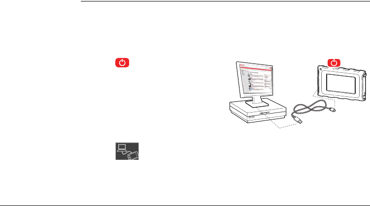
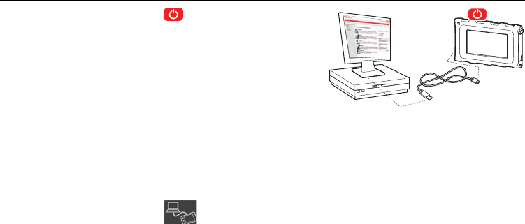
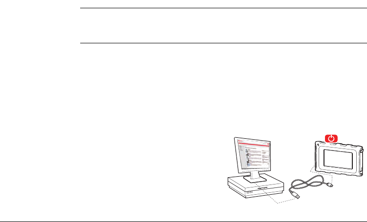
• By synchronisation with the MyWorld homepage on
www.leica-geosystems.com:
1. Press and connect the Control
Unit to the PC via USB cable. The
Control Unit is available as removable
disc at your PC.
2. If the Control Unit does not recognize the PC connection automatically
press .
3. If the connection works, start your internet browser and go to the MyWorld
homepage. Register your product by entering the equipment number that can be
found on the label below the laser distance meter. Refer to "Labelling 3D Disto",
page 179.
3D Disto_011

40
3D Disto, Description of the System
Deviations in 3D Disto Windows Software
1. Install 3D Disto Software on your PC.
2. Start your internet browser and go to the MyWorld homepage. Register your
product by entering the equipment number.
3. Choose the MyProduct page and press the activation key for licenses.
4. Save the license key file in the Licence folder that you can find in directory
C:\Program Files\Leica Geosystems\3D Disto.
• By entering the licence key manually:
4. Choose the MyProduct page and press the activation key for licenses.
5. A standard Windows pop-up prompts to save the license key file. Save the file in
the Licence folder on your Control Unit.
1. Press and go to Menu » Device » Software » License.
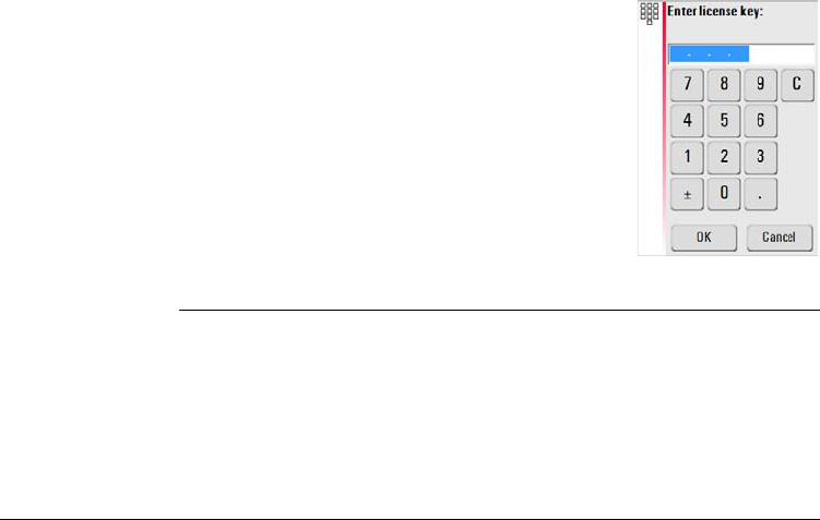
3D Disto, Description of the System 41
2. Enter the key, which you can find on the MyWorld
webpage, and press OK.
The activated application programs are available in the application menu.
42
3D Disto, Description of the System
Software update
2. If the Control Unit does not recognize the PC connection automatically
press .
3. If the connection works, start the internet browser and go to the MyWorld
homepage. Register your product by entering the equipment number.
4. Go to the MyProduct page, choose the latest software version and press the
Save key.
5. A standard Windows pop-up prompts to open or save the file. Save the file in the
Update folder on your Control Unit.
1. Press and connect the Control
Unit to the PC via USB cable.
Ensure the Control Unit battery is fully charged before starting the software
update. Otherwise it can happen the data get lost and you have to restart
the download. Do not disconnect from PC before download has finished.
Please save and export your measurement data before starting the soft-
ware update.
3D Disto_011

3D Disto, Description of the System 43
6. Disconnect the Control Unit from the PC and start installation in Menu » Device
» Software » Update.
Deviations in 3D Disto Windows Software
1. Start your internet browser and go to the MyWorld homepage. Register your
product by entering the equipment number.
2. Choose the MyProduct page, choose the latest software version and press the
Save key.
3. Save the file in the Update folder that you can find in directory C:\Program
Files\Leica Geosystems\3D Disto.

44
3D Disto, User Interface
4 User Interface
4.1 Control Unit
User input The 4.8" touch screen display is the main operation tool for the 3D Disto.
It is used for navigations within the different applications and menus as well to steer
the 3D Disto.
Certain functions can also be managed via RM100 Remote Control.
Leica Geosystems recommends to use the supplied pen on the touch screen.
3D Disto, User Interface 45
4.1.1 Screen
All shown screens are examples. It is possible that local software versions are
different to the basic version.
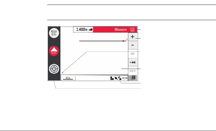
Screen
a) Head line with result window
b) Tool bar
c) 3D Disto position
d) Sketch area / Viewfinder
e) Status bar
f) Main operation bar
S_3D Disto_001
a
b
c
d
f
e
46
3D Disto, User Interface
Description
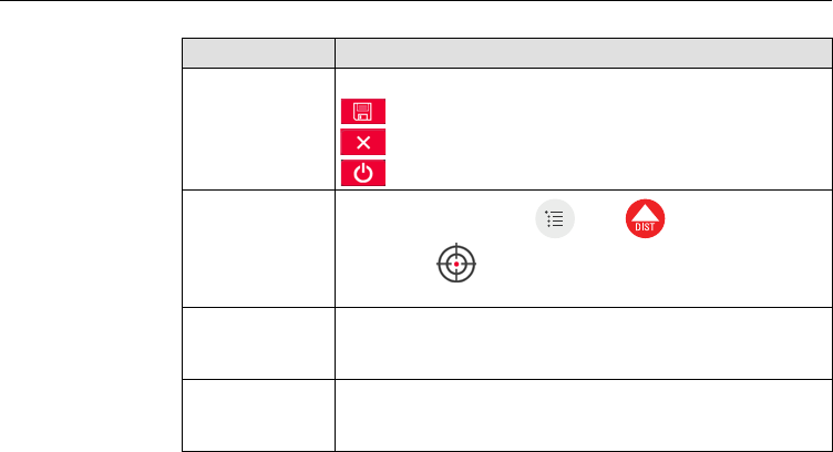
Element Description
Head line Shows the running application.
allows to save and close files.
closes applications.
shuts down the Control Unit.
Main operation
bar Contains the keys Menu , Dist , and
Viewfinder .
These keys are displayed during all applications.
Sketch area, alter-
nating with View-
finder
Displays measured points, lines and areas and correct position
of 3D Disto in relation to measured points - either in foot print
or face mode.
Viewfinder, alter-
nating with sketch
area
Shows the 3D Disto’s live video stream that is used to target
points over longer distances up to 50 m exactly and to take
pictures.
3D Disto, User Interface 47
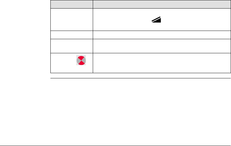
Result window Displays all results like distances, heights, slopes, areas, angles.
With the result choice key you can switch between the
result types. With tip on the results calculator opens.
Tool bar Contains application specific tool keys.
Status bar Displays status of scale/zoom, connections, batteries, time,
running function mode, assistant support.
Hour Glass
Appears in case the software is in the middle of a task. For
example while self-levelling, measurment, saving or exporting
data. No key command is possible.
Element Description
48
3D Disto, User Interface
4.1.2 Main Operation Bar
Main operation bar
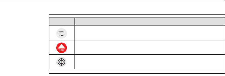
description Key Description
Opens the menu to start applications or to define settings.
Starts measurement.
Opens, closes and locks Viewfinder.
3D Disto, User Interface 49
4.1.3 Tool Bar
Tool bar
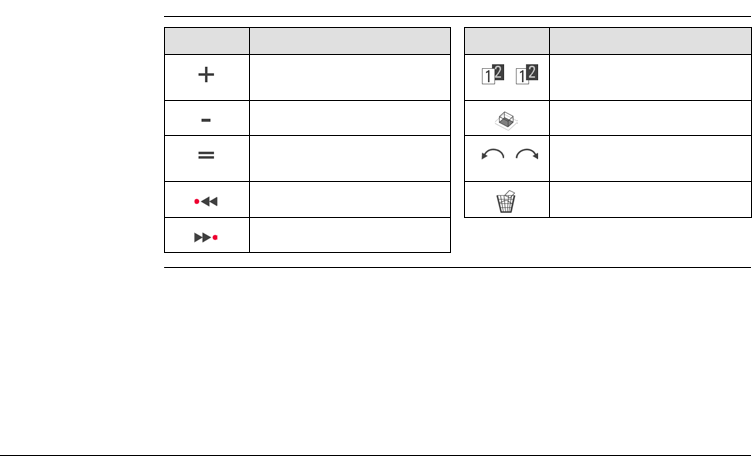
description Key Description Key Description
Add Switch between the tool
bars
Subtract Start area or volume mode
Generate result or close
polygons
Undo or redo last command
Go one point backward Clear functions
Go one point forward
50
3D Disto, User Interface
4.1.4 Icons & Symbols
Common symbols
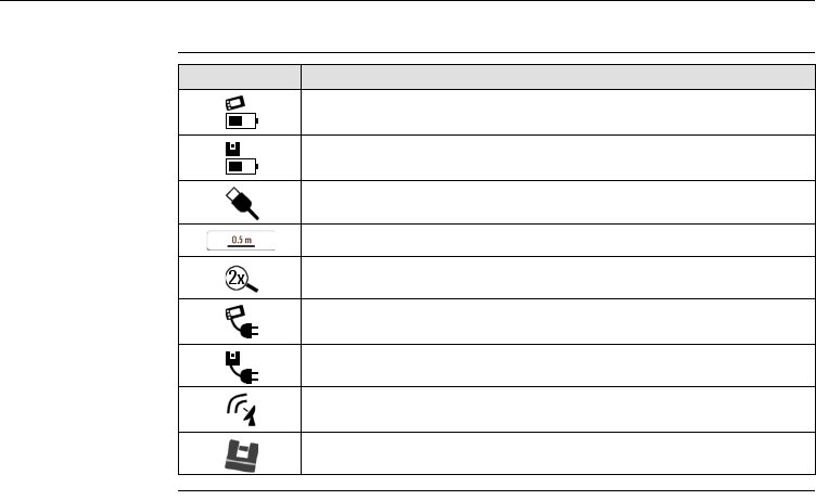
in status bar Icon Description
Indicates the level of the remaining battery capacity for the Control
Unit.
Indicates the level of the remaining battery capacity for the
3D Disto.
Indicates USB connection between Control Unit and 3D Disto.
Scale of Sketch Area.
Indicates zoom level/magnification.
Indicates that Control Unit is connected to power supply or
3D Disto powers Control Unit.
Indicates that 3D Disto is connected to power supply.
Indicates that WLAN connection is working and shows signal
strength.
Indicates that tilt sensor is turned off in the settings.
3D Disto, User Interface 51
Various symbols in
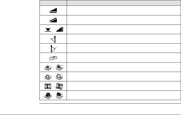
result window Icon Description
Horizontal distance
Tie distance
Height, height difference
Left angle
Right angle
Tilt
Horizontal/tilted area
Horizontal/tilted area perimeter
Volume Height/tilted volume height
Volume/tilted volume
52
3D Disto, User Interface
Room Scan result
symbols
Projector result
symbols
Tool Kit result
symbols
Icon Description
Circle size
Point height
Circumference
Diameter
Scan area
Scan perimeter
Icon Description
Distance between point and plane
Icon Description
Orthogonal distance of a point to the reference line
3D Disto, User Interface 53
4.2 RM100 Remote Control
Description The RM100 Remote Control (IR) has five buttons that allow to turn the 3D Disto and
to execute a distance measurement or point projection, depending on the running
application program.
The RM100 Remote Control does not support the tool kit applications.
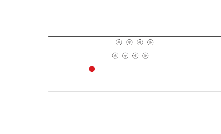
Targeting
procedure
1. Rough targeting: long tip on / / / to turn the 3D Disto as long as
pressed.
2. Fine targeting: short tip on / / / to turn the 3D Disto in small single
steps.
3. Measure: Press .
The red LED at the top of the RM100 Remote Control will blink each time a button is
pressed, indicating that the remote is transmitting to the 3D Disto.

54
3D Disto, Instrument Setup
5 Instrument Setup
5.1 Startup Procedure
Charging / first-time use
• For all batteries
• The battery must be charged prior to using it for the first time because it is
delivered with an energy content as low as possible.
• The permissible temperature range for charging is between 0°C to
+40°C/+32°F to +104°F. For optimal charging we recommend charging the
batteries at a low ambient temperature of +10°C to +20°C/+50°F to +68°F if
possible.
• It is normal for the battery to become warm during charging. Using the
chargers recommended by Leica Geosystems, it is not possible to charge the
battery if the temperature is too high.
• For Li-lon batteries
• For new batteries or batteries that have been stored for a long time (> three
months), it is effectual to make only one charge/discharge cycles.
• For Li-lon batteries, a single discharging and charging cycle is sufficient. We
recommend carrying out the process when the battery capacity indicated on
the charger or on a Leica Geosystems product deviates significantly from the
actual battery capacity available.

3D Disto, Instrument Setup 55
Operation / discharging
• The batteries can be operated from -10°C to +50°C/14°F to +122°F.
• Low operating temperatures reduce the capacity that can be drawn; very high
operating temperatures reduce the service life of the battery.
• Discharge temperature is from -10°C to +50°C/14°F to +122°F.
Inserting and removing the batteries
ƽWarning It is not allowed to use another type of battery or to remove the battery socket on
the 3D Disto or Control Unit. For exchange please contact your distributor or Leica
Geosystems representative.
It is always recommended to shield the instrument from direct sunlight and avoid
uneven temperatures around the instrument.
56
3D Disto, Instrument Setup
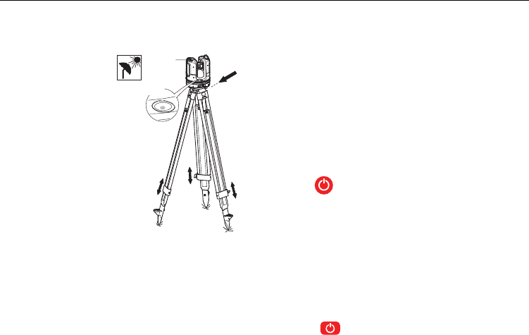
Setup step-by-step The following setup assumes the setup on a tripod but it is also possible to place the
3D Disto on flat surfaces such as floor or boards.
5. 3D Disto starts self-levelling: the tilt is checked by a tilt sensor and the instru-
ment levels itself if the tilt is < 3°.
Refer to "Description of buttons and LEDs", page 29, for information about tilt
status.
6. Turn ON the Control Unit by pressing .
1. Setup the tripod on a suitable place where the
points to be measured are good to target and
extend the tripod legs to a comfortable working
posture.
2. Place 3D Disto onto tripod head. Tighten central
fixing screw of tripod.
3. Centre the circular bubble on the 3D Disto by
adjusting the tripod legs. This is not necessary
with dome-head tripods.
4. Press to turn on the instrument.
Do not move the sensor while self-levelling procedure is working.
2
3
1
4
1
1
3D Disto_012
3D Disto, Instrument Setup 57
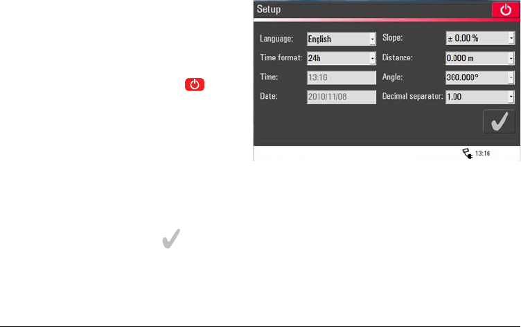
7. If the Control Unit is
started for the first
time the following
screen opens:
With you can
shut down the
Control Unit.
8. Choose a language.
Choose time format (23:59/11:59 am-pm).
Enter date and time.
Choose the units for slope, distance and angle.
Choose decimal separator.
9. Press to go on.
58
3D Disto, Instrument Setup
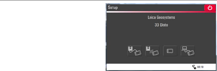
11. Choose one of the following connection options:
• Connect to 3D Disto with USB cable,
• WLAN to 3D Disto,
• to go ahead without connection or
• connect Control Unit to a PC.
10. Following screen
opens:
Using WLAN connection the first time, you have to choose the USB
connection and install the WLAN connection manually in the menu
settings. If it does not work change the WLAN channel.
3D Disto, Instrument Setup 59
12. To work with a cable connection to 3D Disto plug in USB cable and press .
OR:
To work with WLAN press .
OR:
To transfer data from or to a PC press . Refer to "5.4.4 Data Transfer" for
more information.
13. Next screen appears to check correct setup and tilt of the 3D Disto. Press to
go on.
It is recommended to plug in the USB cable before turning on the
3D Disto, otherwise the instrument starts self-levelling procedure
again.
Do not extend the USB cable with an adapter and only use the Leica
Geosystems cable delivered in the container.
If connections do not work press Menu » Device » Connect 3D Disto
and activate connection manually, either to PC or to Control Unit by
WLAN or cable.
60
3D Disto, Instrument Setup
ƽCaution For experts only:
If the tilt sensor is OFF the system does not compensate the tilt of the 3D Disto. In
consequence all results that refer to a physically horizontal plane, for example tilt,
height differences, horizontal distances, angles, areas, or volumes, now refer to the
tilted horizon of the laser unit. Only the tie distance between to measured points is
independent of the Tilt Sensor's setting.
If the setup screen indicates tilt > 3° adjust the tripod legs to level the
circular bubble or change 3D Disto position to a more suitable and flat
surface. Await green LED, then press .
14. If 3D Disto can not be
levelled a pop-up
prompts to deactivate
the tilt sensor. If not
needed, press OFF. A
symbol in the status
bar reminds you that
the tilt sensor is off.

3D Disto, Instrument Setup 61
It can be useful to disable the Tilt Sensor in case of vibrations, for example on the
construction sites, or under instable or moving environments like on boats. Almost
all measurements can be done nevertheless; exported data can be "levelled" after-
wards via CAD software.
15. Sketch area appears. System is ready for measurement.
62
3D Disto, Instrument Setup
5.2 Assistant
There is an assistant available that will guide you through all measurement tasks with
illustrated pop-ups. If not needed, it can be deactivated in Menu » Settings »
Assistant.
3D Disto, Instrument Setup 63
Assistant and
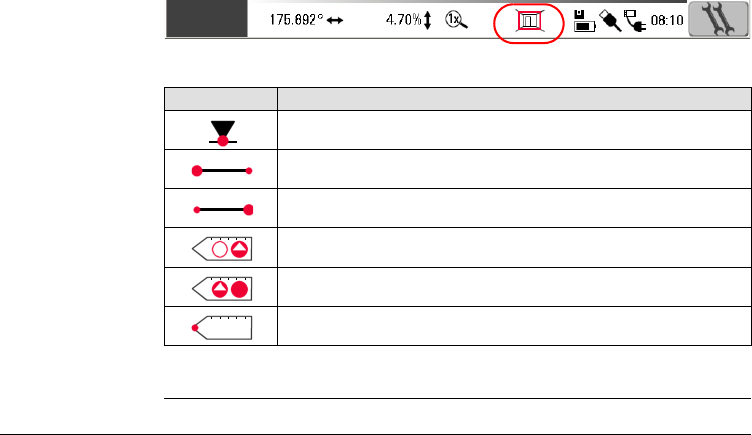
supporting icons
If assistant is deactivated there are still supporting icons in the status bar, showing
which application is running and what user action is required.
Examples* of supporting icons:
* Not all supporting icons are listed here.
Icon Description
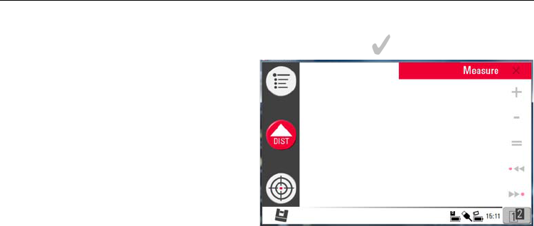
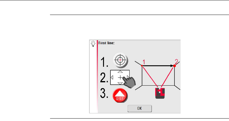
Measuring height activated.
Measuring “First Line” first point.
Measuring “First Line” second point.
Hidden Point Mode: measure first point.
Hidden Point Mode: measure second point.
Hidden Point Mode: peak of ruler calculated.
64
3D Disto, Instrument Setup
5.3 Device Configuration and Menu Settings
Device
configuration
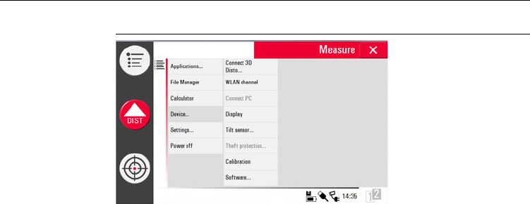
All settings of the setup screen can also be edited and changed in the menu:
Choose Menu » Device.
•Connect 3D Disto to connect by WLAN, USB cable, or disconnect Control Unit.
•WLAN channel to switch between different channels if connection does not
work.
•Connect to PC to allow data transfer.
•Display to improve display settings.
•Tilt sensor to activate/deactivate.
3D Disto, Instrument Setup 65
•Theft protection to protect instrument by safety pin.
•Calibration to check and adjust. Refer to "9 Check & Adjust" for more informa-
tion.
•Software to update software, to check software version on the Control Unit and
the 3D Disto or to enter the software license key.
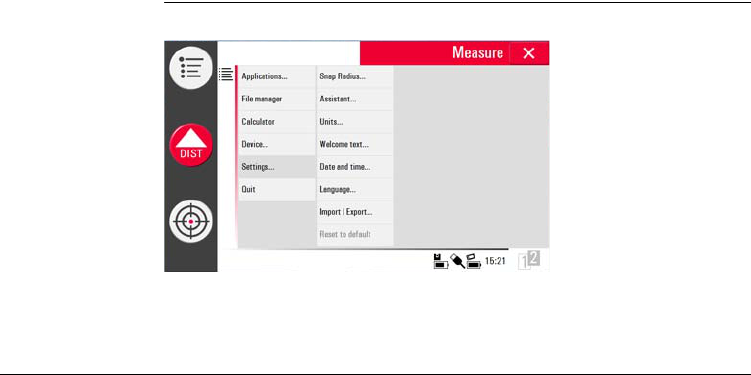
Menu settings Press Menu » Settings, the following options appear:
•Snap Radius is an option to define the area around a point/line. This setting
offers a list of points that are very close to each other to simplify their selection.
•Assistant to activate/ deactivate the assistant.

66
3D Disto, Instrument Setup
•Units to change the unit settings.
•Welcome text to enter for example company name.
•Date & Time to change date and time settings.
•Language to choose your preferred software language.
•Import/Export settings are only available with particular application programs.
Refer to the detailed description in "5.4.2 File Manager".
• The instrument has a Reset function.
If you select the menu function Reset and confirm, the device returns to the
factory settings and stack and memory are cleared.
All customised settings and stored values are also lost.
3D Disto, Instrument Setup 67
5.4 Data Management
5.4.1 General
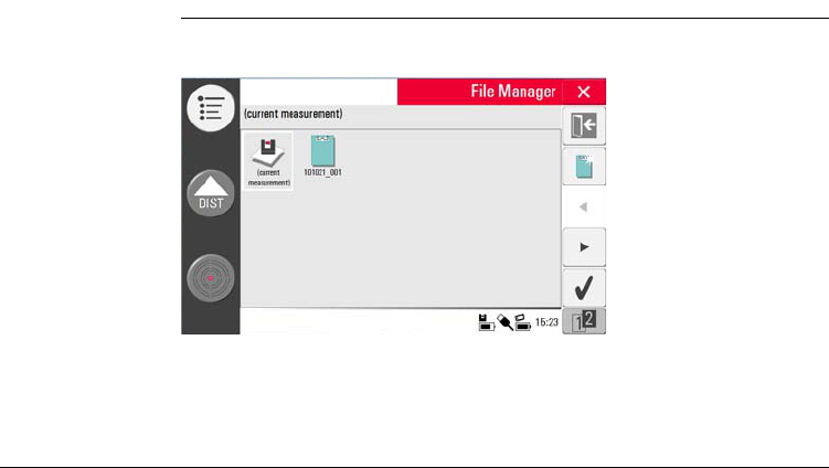
File manager The File Manager covers the entire data administration of measurement files, photos,
Secure Points and data transfer.
68
3D Disto, Instrument Setup
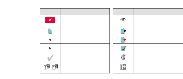
Description of keys
Key Description Key Description
Close folder/File Manager Viewer. Inactive in Project
Folder level
Create folder Data import
Scroll back Data export
Scroll forward Rename folder/edit file info
Select function Clear
Switch between the tool
bars
Lead to upper folder level
or close file manager
3D Disto, Instrument Setup 69
5.4.2 File Manager
Description To start, press Menu » File Manager.
Description of keys
For some applications the File Manager will be started automatically.
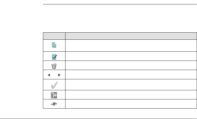
Key Description
To create a folder and enter folder name with maximum 15 characters.
Date and ID are default name.
To rename a folder or to edit file information.
To clear a selected file or folder.
To to choose a file or folder.
To open a selected file or folder.
Exit Icon... to go back a level.
To view a Secure Point or photo file.
70
3D Disto, Instrument Setup
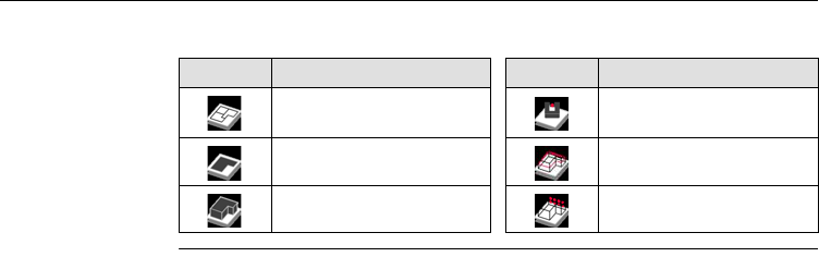
All files are displayed with different icons to differentiate the type of meas-
urement files:
Key Description Key Description
Standard Measurement
files
Open File / temporary file
Area Measurement Room Scan file
Volume Measurement Projector file
3D Disto, Instrument Setup 71
5.4.3 Photo and Secure Points Administration
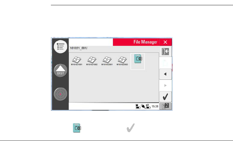
Description A folder for photos and Secure Points is created if a photo was made and the meas-
urement was stored.
• Press to select, and press to open the folder.
In case a folder contains Secure Points there will be an advice Folder
contains Secure Points. Continue? Yes/Cancel?

72
3D Disto, Instrument Setup
• Press arrow keys / to choose a photo, press to open the file.
• Press to view a photo.
• Press to clear a selected or all photos.
• Press to close gallery.
3D Disto, Instrument Setup 73
5.4.4 Data Transfer
Whilst other USB memory sticks may be used, Leica Geosystems recommends Leica
industrial grade USB memory sticks and cannot be held responsible for data loss or
any other error that may occur when using a non-Leica USB memory stick.
Data Import For some application it is possible to import DXF files. Data should be prepared on
the PC before. Only points are imported, no lines. Optional the data source can be a
PC or USB stick that is plugged into the Control Unit.
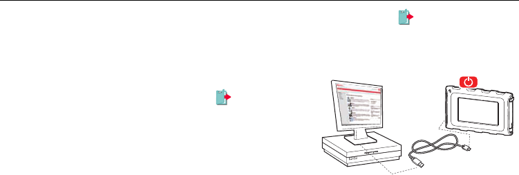
USB Cable
Remove unneeded data such as frames, logos, coordinates, or orienta-
tion arrows, in the DXF files before importing them.
1. For import from PC, connect
powered Control Unit and PC by USB
cable.
3D Disto_011

74
3D Disto, Instrument Setup
2. Pop-up PC connection active appears on Control Unit screen. The Control Unit
is now out of work and entirely controlled by the connected PC.
3. If connection is not working go to Menu and select Connect to PC.
4. After successful connection, a pop-up window with Import folder appears.
5. Copy the files from PC to the Import folder of the Control Unit and close the
window.
6. Disconnect Control Unit by choosing Disconnect Hardware at your PC or by key
press in the pop-up of the Control Unit.
7. Open File Manager and press . Available DXF files are listed. Choose a file and
press .
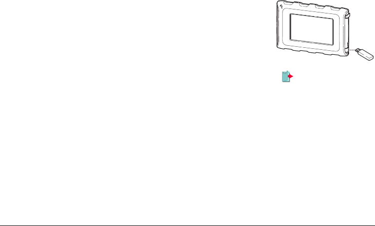
USB Stick
1. For transfer from USB stick, plug stick into your PC and save DXF files in the
Import folder on the USB stick. Disconnect USB stick from your PC.
2. Plug USB stick into Control Unit.
3D Disto_036
3D Disto, Instrument Setup 75
3. Pop-up Import from mass storage device? Yes/Cancel appears on Control
Unit screen.
4. If Yes: File Manager opens. Press . Choose the file and press .
5. If finished, USB stick just needs to be unplugged.
Deviations in 3D Disto Windows Software
1. Save the DXF file in the Import folder that you can find in directory C:\Program
Files\Leica Geosystems\3D Disto.
2. Open File Manager and press , select a DXF file and press to open it.
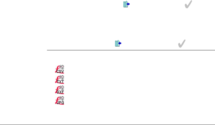
Data export Data Export is started in the File Manager.
The following data formats are supported and available for export:
• : Measurement (*.CSV). List separator is ; (semicolon).
• : Measurement (*TXT). List separator is a tabulator sign.
• : Drawing (*.DXF)
• : Photos, single pictures (*.JPG)
76
3D Disto, Instrument Setup
1. To export files or folders choose a folder or file, press .
2. Export data are generated and can be transferred to a connected PC or USB stick.
USB Cable
2. Pop-up PC connection active appears on Control Unit screen.
3. If connection is not working go to Menu and select Connect to PC.
4. For a successful connection, a pop-up window with EXPORT folder appears on
your PC screen.
5. Copy the files to the PC and close the window.
6. Disconnect Control Unit by choosing Disconnect Hardware at your PC.
1. Open File Manager, choose a folder
or file and press . Connect
powered Control Unit and PC by USB
cable.
3D Disto_011
3D Disto, Instrument Setup 77
USB Stick
2. Open File Manager, choose a folder or file and press .
3. Pop-up Export to mass storage device? Yes/Cancel appears on Control Unit
screen.
4. If Yes: export data are transferred to USB stick.
5. If finished, USB stick just needs to be unplugged.
1. For transfer to USB Stick plug stick into Control
Unit.
If you execute export in File Manager and plug in the USB stick after-
wards, no data will be copied to the USB stick unless you repeat the
export function.
3D Disto_036

78
3D Disto, Instrument Setup
Deviations in 3D Disto Windows Software
1. Open File Manager, choose a file and press
Save the DXF file in the Import folder that you can find in directory C:\Program
Files\Leica Geosystems\3D Disto.
2. You can find the export data in the Export folder that you can find in directory
C:\Program Files\Leica Geosystems\3D Disto on your PC.
3D Disto, Instrument Setup 79
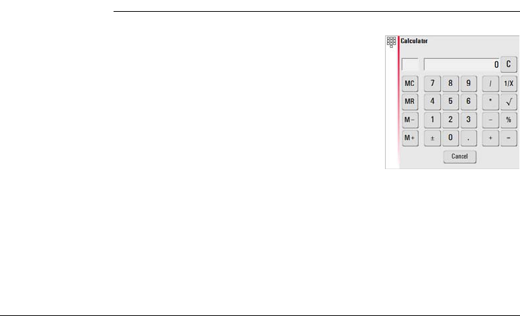
5.5 Calculator
Using calculator 1. Press Menu » Calculator.
3. The memory function allows among other things to add or subtract, for example
area, volumes or other results.
• Click MC to clear memory.
• Click MR to retrieve a number that is stored in memory.
• Click M- to subtract the displayed number to the number that is already in
memory.
• Click M+ to add the displayed number to the number that is already in memory.
4.
2. A pop-up opens with the following keypad:
80
3D Disto, Instrument Setup
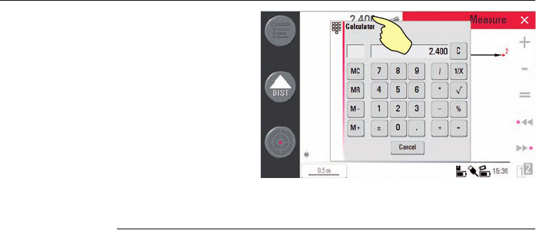
Press Cancel to close the window again.
Calculation will not be saved in the running measurement file after closing.
Another option is to tip on
the result in the result
window in order to calcu-
late with this value.

3D Disto, Operation 81
6 Operation
6.1 Measurements
Description The 3D Disto is a combination of a precise laser distance meter (LDM) and angle
encoders. Targeting with the visible red laser beam allows to measure the distance
between the 3D Disto and the target and horizontal and vertical directions towards
the target. Basic usage of the measurements is the determination of the relations
between different targets, such as horizontal distances, tie distances, height differ-
ences, for example for identifying room dimensions, height differences, angles from
wall to wall, area sizes, volumes, plumb points or other measures.
The 3D Disto supports the measuring and targeting even in difficult situations such
as targeting over long distances, at targets difficult to reach or at bright light condi-
tions. An inbuilt tilt sensor ensures measurements following true horizon or true
plumb line, defined by gravity.
82
3D Disto, Operation
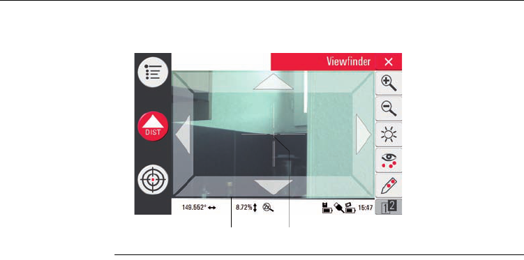
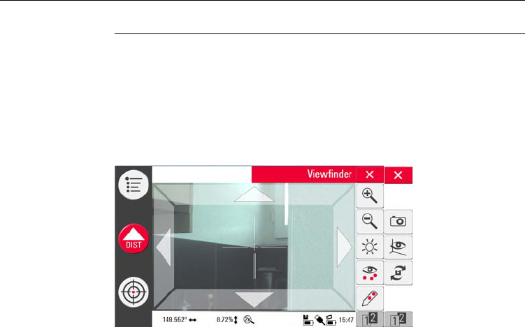
6.2 Viewfinder
Description The 3D Disto has an integrated camera. The camera is accessible via the Viewfinder,
it shows the camera image directly on the Control Unit display. The crosshair in the
Viewfinder image allows precise targeting and measurements even if the laser beam
is not visible, for example over long distances or because of bright backlight condi-
tions. The integrated digital zoom allow the image to be magnified up to eight times
of its original size. This is a great help because precise measurements on detailed
surfaces can even be accomplished in sunlight without any problem.
Example of a Viewfinder screen, first and second toolbar shown:

3D Disto, Operation 83
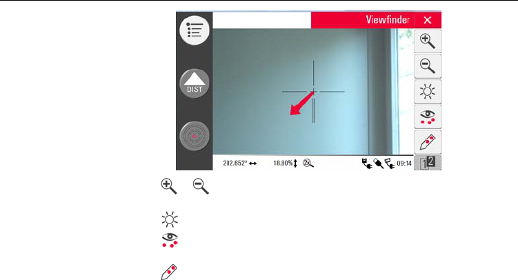
Using Viewfinder
step-by-step
1. Press to start the Viewfinder. A second key press activates the lock mode,
a third one unlocks and closes the Viewfinder.
2. Targeting: There are different options to target a measure point:
• Press the arrow keys in the screen for targeting, long press for fast 3D Disto
turns and short press for single step turns.
•PinPoint Targeting: tip on a position on the screen. Laser point turns to this
point automatically.
•Joystick Targeting: is activated by long tip in the centre of the crosshair. A
red dot in the centre appears. With finger or pen sliding on the screen 3D Disto
turns real-time in this direction until red arrow is released. The longer the red
arrow is the faster the 3D Disto turns.
A lock symbol on a key indicates the lock mode.
84
3D Disto, Operation
3. Press or to zoom in and out. There are four magnifications available. The
running setting is shown in the status bar.
4. Press to adjust the brightness of the camera.
5. Press to display/hide all measured points. Last measured point is always
displayed.
6. Press to measure covered points. Place the peak of the ruler for offset points
to the point.
• Target laser point on the mark at the opposite end of the ruler.
Do not move ruler from now on.
3D Disto, Operation 85
•Press .
• Target second mark.
•Press .
• A pop-up with checkmark confirms successful measurement.
7. Press to take pictures for documentation purposes. They are stored with
name, point ID, date and time information.
8. Press in dark environmental conditions to change Viewfinder picture in nega-
tive mode. Edges and corners will be highlighted in black. Only available in
windows version.
9. Press to choose between different turn commands:
• Turn 90° right
•Turn 90° left
• Turn ?°: Enter the horizontal angle through which the 3D Disto shall be turned.
• Horizon: 3D Disto goes to 0% slope/horizontal position.
• Plumb up: This option can be used to plumb up a point by setting up the
3D Disto exactly over it. Just mark a cross on the floor. Ensure that the lines of
the cross are exactly 90° to each and long enough to be seen when setting up
the instrument above. Use the 90° markings on the socket for centering.

86
3D Disto, Operation
Please note that there are vertical and horizontal deviations in the
movements. Do not use the turn commands for stake-out or align-
ment. Please work with tools from the Tool Kit instead.
3D Disto, Operation 87
6.3 Measurement Workflow
Description The Measure application allows to measure horizontal distances, tie distances, height
differences, heights, angles, areas, volumes, slopes, or perimeter of points indoors
but also outdoors on buildings and sites.
Measurements
step-by-step
3D Disto_050
12
34
5
6
88
3D Disto, Operation
To measure for example a rooms’ dimension, carry out the following steps:
1. Start up the system as described in "5.1 Startup Procedure".
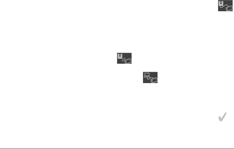
3. To target the first point, for example a corner, press and use the arrow keys
or another method as described in "6.2 Viewfinder" to move the laser point to
the desired position.
2. The following screen
appears:
While targeting ensure the laser beam is not split for example by
corners or edges. Otherwise this could lead to wrong measurements.
If laser point becomes a line due to an acute target angle to a wall the
system measures with the centre of the line.
3D Disto, Operation 89
4. Press to measure. Measured point appears in the sketch area.
Measuring errors can occur when measuring toward colourless liquids,
for example water, or dust free glass, Styrofoam or similar semi-perme-
able surfaces.
Aiming at high gloss surfaces may deflect the laser beam and lead to
measurement errors. Against non-reflective and dark surfaces the
measuring time may increase.
The position of the 3D Disto symbol in the sketch changes in correct
relation to the measured point. First measured point is always
displayed on the left side of the sketch area.
5. Target the second
point and proceed as
described in 3. to 4. A
line is displayed from
first to second meas-
ured point.
90
3D Disto, Operation
First two points define the measuring geometry, the so called Base
Line, and must be measured in horizontal distance of at least 10 cm.
The Base Line is always displayed horizontally in the sketch area.
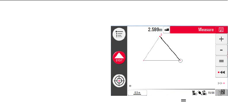
6. After the third point
was measured a
proposed "closing line"
appears between first
and latest measured
point. The selected line
is always highlighted
with a bold line and
arrow in measurement
direction.
7. Proceed as described for measuring further points or use to close/finish the
polygon.
In special situations the proposed line is not available. Polygons can
also be closed and result created by drawing a line with the pen
between the two points to be connected.
3D Disto, Operation 91
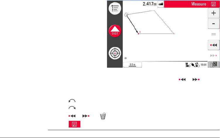
9. Proceed as described before to measure the ceiling dimensions.
10. Press to undo the latest command.
11. Press to redo the latest command.
12. Press or and to clear measurements and results.
13. Press to choose between save, save as, clear screen or cancel.
8. To measure the room
height select a floor
point in sketch area
and target and
measure ceiling corner
above.
Please note that the sketch shows a foot print view. Measured floor
point and ceiling point may cover each other. Use or to select
points and get the height result.

92
3D Disto, Operation
6.4 Touch Screen in Sketch Area
Selection of
elements
Any element can be selected by finger tip or with pen, too. Polygons that consist of
added or subtracted lines can not be selected by direct tip.
Line drawing
between arbitrary
points
This is a feature to determine results, not to draw the line.
The key of the toolbar only accepts a line which is proposed by the system. And
these proposed lines are always connected to the last measured point.
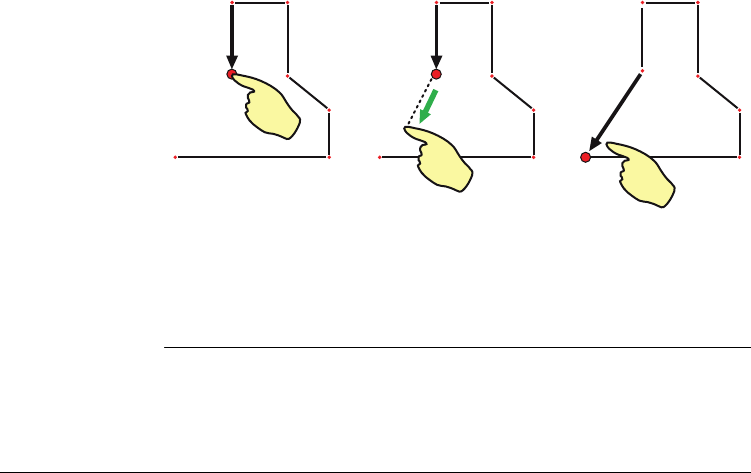
With the Line drawing between arbitrary points feature two points can be
connected that were not measured in sequence.
3D Disto, Operation 93
Select point. Keep finger or pen on
screen and slide to desired
point.
Release touch screen when
dotted line changes to
dashed line. Results
between these two points
are displayed in the result
window.
7 7
3D Disto_047
94
3D Disto, Operation
6.5 Addition and Subtraction
During and after the measurement you have the option to add or subtract selected
elements.
The following values can be added:
• Horizontal distances
• Tie distances
Area and Volume results can be added or subtracted by using the memory function
in the calculator.
Addition and
subtraction after
measurements
step-by-step
1. Select element by fingertip, pen or / .
2. Press or for addition or subtraction. The corresponding symbol appears
in the status bar. Selected line or area is highlighted with black bullet symbol.
3. Select next element and press or for addition/subtraction again or to
close the sum and/or finish the adding/subtracting function.
3D Disto, Operation 95
Addition and
subtraction during
measurements
step-by-step
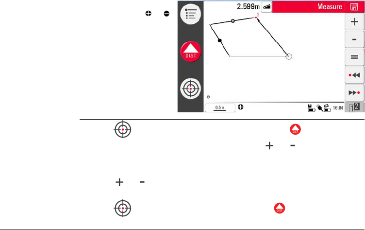
1. Press , target and measure the first two points with .
2. Two points with line connection appear in sketch area.
3. Press or for addition or subtraction. The corresponding symbol appears
in the status bar. Selected line is highlighted with black bullet symbol.
4. Press , target to measure a further point. Press .
4. The added/subtracted
elements get a or
icon.
5. The sum is displayed in
the result window.
You have to measure two points before or is active as points
can not be added or subtracted.

96
3D Disto, Operation
5. Press or to add/subtract next distance (line) or continue to measure if
you would like to skip a point distance to be added/subtracted.
6. Proceed that way until you would like to close the sum and/or finish the
adding/subtracting function. To do so press .
3D Disto, Operation 97
6.6 Area & Volume Calculations
Description The 3D Disto also features to measure areas and volume. Both can be determined
while measuring or after measurements.
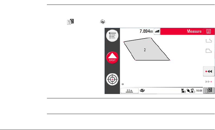
1. Press and choose .
Each area can be managed in both applications, Horizontal Area or Tilted Area appli-
cation.
2. A pop-up prompts to
decide between hori-
zontal area/volume,
tilted area/volume or
quit the application.
The sketch areas'
content is kept but the
toolbar changes.
98
3D Disto, Operation
6.6.1 Horizontal Areas/Volumes
Calculation during
measurements
step-by-step
1. Either select start point in sketch area or open Viewfinder if sketch is empty.
2. Target and measure a point with . Viewfinder is closed and point displayed in
sketch.
3. Press and measure next point with .
4. Press to define line as part of the area. Proceed with measurement and line
selection. The polygon can be closed by pressing . The area is highlighted in
grey colour.
5. Pop-up asks Measure Volume?Yes/No?
6. If Yes pop-up appears to choose between the different options to define the
height: Enter height for volume, measure height, Cancel.
7. Measure height:
Viewfinder opens, target and measure point on floor with followed by point
on ceiling. The height appears in the result window.
OR:
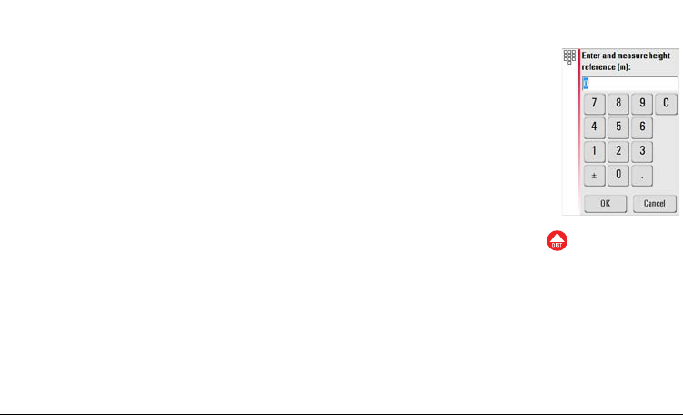
8. Enter height: Default for the entry is 0.000 m. Enter a desired value and press
OK or Cancel.
You can measure the points anywhere on the floor or ceiling area.
3D Disto, Operation 99
OR:
9. Cancel: the result is an area.
10. To change the height or to calculate the volume with a selected area press or
and proceed as described in steps 3. to 4.
Calculation after
measurements
step-by-step
1. Select line to be added to area and press .
2. Proceed that way for all lines and press .
3. For volume calculations go on as described from 5. to 10., page 98.
4. Quit application pressing .

100
3D Disto, Operation
6.6.2 Tilted Areas
Description • This option offers the same functionality as the Horizontal Area application but
the results differ.
• The result window shows the tilted area, tie distances, tilt perimeter and tilt of
the plane.
• A arrow in the tilted area shows the tilt direction.
Volume calculation with tilted areas is also possible.

3D Disto, Software Applications 101
7 Software Applications
7.1 Overview
Description There is a variety of software application programs available that cover a wide spec-
trum of construction tasks and facilitate daily work.
Following application programs are available:
•Comfort Tools:
Software license that features a Tool Kit with smart measuring and set-out tools
and stationing for secure, check and relocate the position of the 3D Disto.
•Room Scan:
Provides practical features to measure room dimension, walls, windows, stairs
and other details with reference height, manually or automatically.
•Projector:
Features layout of grids and other designs on floor, ceiling or walls.

102
3D Disto, Software Applications
7.2 Tool Kit
General In addition to the standard application this program features:
The Tool Kit applications offer quick, precise and easy-to-use tools for plumbing,
meter marks, heights and parallels. After each layout task the respective tool has to
be restarted. A pop-up prompts to go on with same reference or to measure a new
one. Data are not stored and can not be imported or exported. Remote Control func-
tionality is not supported in these applications.
• Comfort
Plumbing,
• Comfort
Targeting,
• Comfort Level,
• Meter Mark,
• Height Tracking
and
• Parallel Line.
3D Disto, Software Applications 103
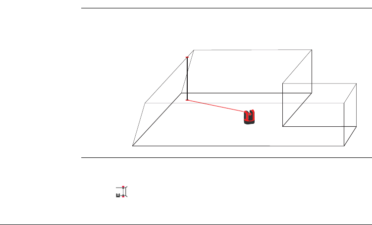
7.2.1 Comfort Plumbing
Description Comfort plumbing allows to plumb any point up or down without standing above it.
For example, this tool can be very helpful for installation of dry walls.
Comfort plumbing
step-by-step
1. Start application in Menu » Applications » Tool Kit.
2. An empty sketch opens. The running applications stays in the background.
3. Press in Tool bar.
4. Viewfinder opens. Target and measure the point that shall be plumbed.
3D Disto_038

3D Disto, Software Applications 105
7.2.2 Comfort Targeting
Description Comfort targeting allows to lay out a point relative to a reference point on vertical
surfaces.
For example, this tool can be very helpful to install lights or pictures in regular
distances on walls.
Use this feature only on vertical surfaces. On tilted surfaces the layout position is not
correct.
3D Disto_039
2.0 m
0.5 m
106
3D Disto, Software Applications
Comfort targeting
step-by-step
1. Start application in Menu » Applications » Tool Kit.
2. The running applications stays in the background.
3. Press in Tool bar.
4. Viewfinder opens. Target and measure reference point on the wall. Press .
5. Pop-up prompts to enter value for right or left distance to reference point. For
left turn set a negative value. Press OK to confirm the value.
6. Laser point blinks to indicate exact position. Pop-up appears to enter vertical
value (= distance above/below layout point). Default value = 0. Set a negative
value for down turn. Press OK to confirm the value.
7. 3D Disto turns and layouts the correct position.
8. Laser point blinks to indicate exact position.
9. Press to close Tool Kit.
Enter 0 to only lay out points vertical to the reference point.
Refer to "8 Error Messages" for information about possibly appearing
error messages.
3D Disto, Software Applications 107
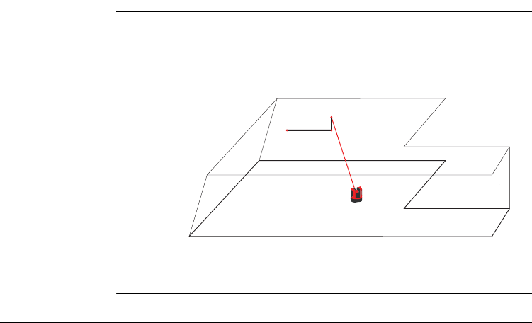
7.2.3 Comfort Level
Description Comfort levelling keeps the laser point on the same level when you turn the 3D Disto
horizontally.
For example, this tool can be very helpful for installation of suspended ceilings or to
mount pictures at the same height on walls.
108
3D Disto, Software Applications
Comfort levelling
step-by-step
1. Start application in Menu » Applications » Tool Kit.
2. The running applications stays in the background.
3. Press in Tool bar.
4. Viewfinder opens. Target and measure reference height on the wall. Press .
5. Viewfinder stays open. Roughly target the assumed layout point and press .
Laser point blinks to indicate the exact height position.
6. Press to close Tool Kit.
Refer to "8 Error Messages" for information about possibly appearing
error messages.
3D Disto, Software Applications 109
7.2.4 Meter Mark
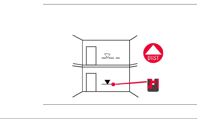
Description The Meter Mark tool refers to a meter mark or reference height and allows to layout
any desired height.
For example, this tool can be very helpful to mark the meter mark at several places
in a room or layout heights over several building levels.
110
3D Disto, Software Applications
Meter mark step-
by-step
1. Start application in Menu » Applications » Tool Kit.
2. The running applications stays in the background.
3. Press in Tool bar.
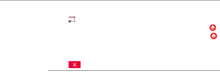
4. Pop-up prompts to enter the height and measure that reference height.
5. Viewfinder opens to target and measure reference point on the wall. Press .
6. Pop-up prompts to enter an absolute height that is intended to be laid out.
Default = reference height.
7. Viewfinder opens. Roughly target to a wall close to expected absolute height.
Press .
8. Laser point blinks to indicate the exact position of the absolute height.
9. Press to close Tool Kit.
Refer to "8 Error Messages" for information about possibly appearing
error messages.
3D Disto, Software Applications 111
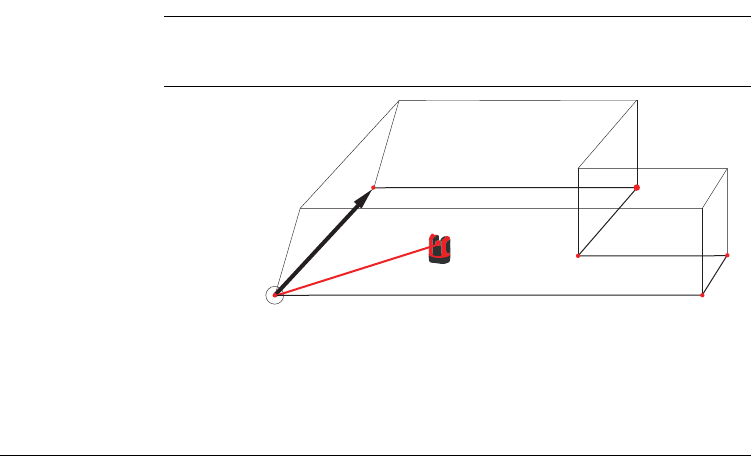
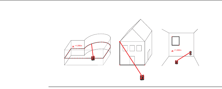
7.2.5 Height Tracking
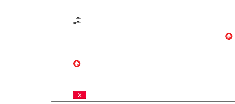
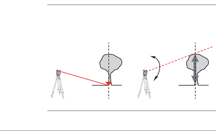
Description Height Tracking allows to determine the height of a target that can not be measured
directly.
For example, this tool can be very helpful for measuring the height of a tree or power
lines.
3D Disto_035
H
Ref
112
3D Disto, Software Applications
Height tracking
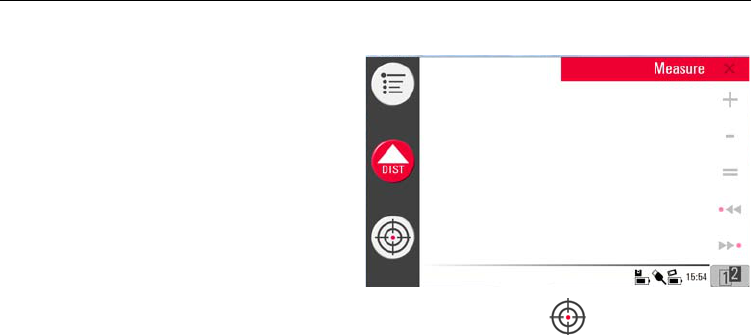
step-by-step
1. Start application in Menu » Applications » Tool Kit.
2. Press in Tool bar.
3. Viewfinder opens. Target and measure a reference point of the same horizontal
distance as the point that you would like to measure indirectly.
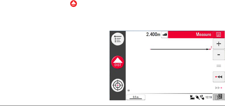
4. Viewfinder stays open and measured point is displayed.
5. Target the point you would like to measure indirectly as exact as possible. The
height difference to the reference point is displayed and updated in real-time in
the result window.
6. Close the Viewfinder to finish the application.
Do not move too much the 3D Disto horizontally after reference point
has been measured, otherwise result is not correct.
3D Disto, Software Applications 113
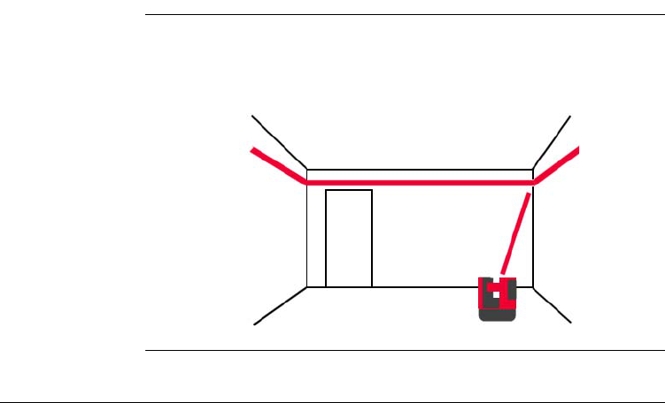
7.2.6 Parallel Line
Description Parallel line allows to lay out parallels to a reference line on plane surfaces like walls
or floors.
For example, this tool can be very helpful to align tilings or panels to a wall.
114
3D Disto, Software Applications
Height tracking
step-by-step
1. Start application in Menu » Applications » Tool Kit.
2. Press in Tool bar.
3. Viewfinder opens. Target and measure start point and end point of the reference
line.
4. A pop-up prompts to enter parallel distance to the left or right of the reference
line. Enter negative values for left distance. Press OK to confirm the value.
5. Viewfinder opens to roughly target layout point. Press . Laser point blinks to
indicate the exact position on the parallel.
6. Press to close Tool Kit.
End point is the upper point in the sketch.
3D Disto, Software Applications 115
7.3 Location
Description The Location function allows to determine the 3D Disto’s position in a pre-defined
coordinate system or room geometry. Reference points or Secure Points are placed
by the user and allow a comfortable handling of the positioning procedure.
Secure Location
step-by-step
If you want to continue a measurement in the same room at a later time and secure
the actual position of the 3D Disto and the measuring geometry, you can measure
and save Secure Points.
You have to measure two points first before Secure Points can be
saved.
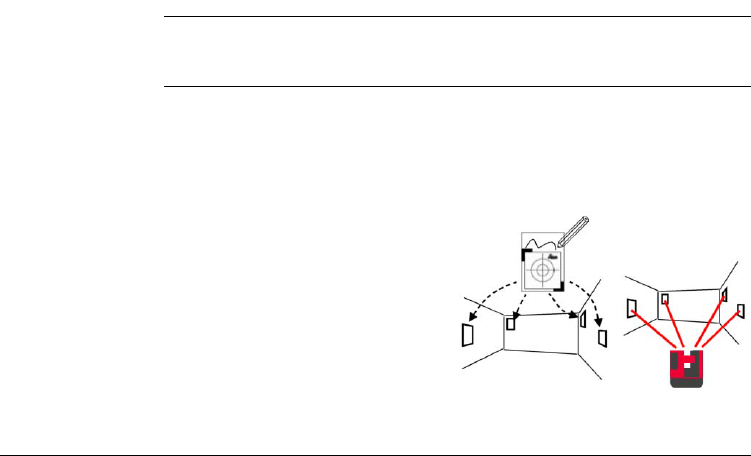
1. Name and place three to five self-
adhesive target marks on walls,
ceiling or floor around your working
area. Ensure that the target marks
are arranged all-over.

116
3D Disto, Software Applications
2. Press Menu » Applications » Location » Secure Location.
3. Viewfinder opens. Target the Target marks as precise as possible and press
to measure.
4. 3D Disto takes a photo and saves it with coordinates, named with ID and date.
5. Pop-up prompts Measure more Secure Points? Yes/No?.
6. Proceed as before and measure at least three Secure Points. After saving a
minimum of three points you may leave the application by choosing No.
Relocation step-
by-step
This feature allows the relocation of the 3D Disto into a defined coordinate system
that previously was fixed by the Secure Location procedure, for example to complete
a previous measurement.
Instead of target marks you can use any other point that is well fixed:
draw a cross on the wall or hang the ruler for offset points on a nail
and use one of it's marks.
You can add further Secure Points later at any time.
Ensure you have enough well-measured Secure Points around your
working area. Even if one is lost there must be three at least for a
successful Relocation.
Use a 3D Disto position that allows to measure at least three Secure
Points around your working area.
3D Disto, Software Applications 117
1. Press Menu » Applications » Location » Relocation.
3. If there are no Secure Points in the memory, pop-up prompts No secure point
in this folder.
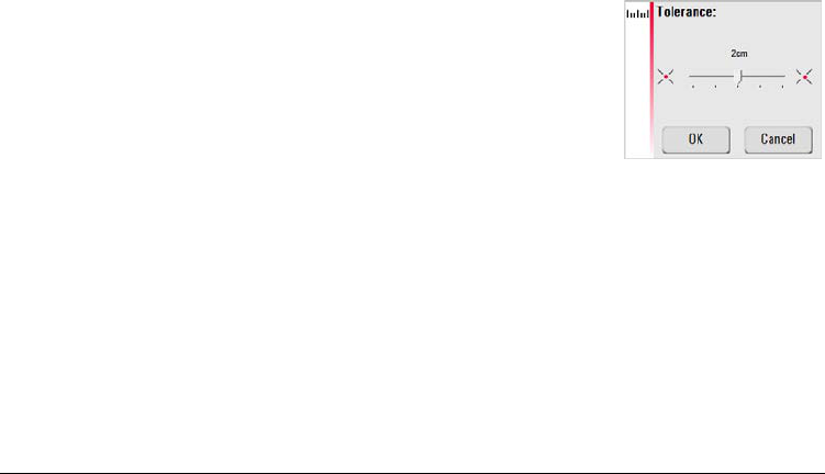
2. A pop-up prompts to define the
tolerance.
Press OK to confirm the value.
A lower tolerance increases the
precision of your measurement
and requires excellent accuracy
and visibility of the Secure
Points.
If there are no Secure Points available but your measurement must fit
to the geometry of a previous one, just start your measurement with
the same Base Line points, which are the first two points of a meas-
urement.
118
3D Disto, Software Applications
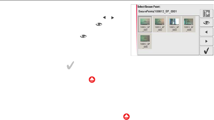
5. Press to confirm point.
6. Viewfinder opens. Target as precise as possible the target mark shown in the
photo and press .
7. If successful, pop-up appears Measure next Secure Point? Yes/Cancel.
8. If Yes: Folder opens to choose next Secure Point. Proceed as described in 4. to
7. for 2nd and 3rd measuring point.
9. When you have measured three points successfully a pop-up requests OK.
Measure more Secure Points? Yes/No/Cancel?.
4. If Secure Points are available folder
opens. Choose a Secure Point by
pressing the arrow keys / or by
tip on screen. Press to enlarge.
Tip on to view Secure
Points before selecting it.
If the first two Secure Points were measured successfully the 3D Disto
roughly turns to the next chosen Secure Point. You just have to do the
fine targeting and press .
3D Disto, Software Applications 119
10. To continue press Yes and proceed as described in 4. to 7.
11. If finished press No, pop-up prompts 3D Disto shift ok; Position: XXXm;
Height: XXXm; OK/Cancel”? Accept with OK or Cancel to measure further
points.
12. If Relocation was not successful pop-up prompts Out of tolerance! Measure
more Secure Points? Yes/No/Cancel. Go on as described in 4. to 11.
13. Press to close the application.
Location Check
step-by-step
If the 3D Disto's socket was moved unintentionally, for example by a bump, all
following measuring points do not fit any more to the geometry of the previous ones.
Start a Location Check to sustain the actual accuracy/geometry.
1. To initiate a Location Check press Menu » Applications » Location » Location
Check.
2. If there are no Secure Points in the memory, pop-up prompts No Secure Point
in this folder. Press OK. Location Check is closed.
3. If Secure Points are available, select Secure Point and press . The 3D Disto
will target the Secure Point automatically. Check laser point position with target
mark.

120
3D Disto, Software Applications
4. Press to close Secure Point gallery.
All Location application can be chancelled by key press.
If laser point does not target the centre of the target mark Relocation
is recommended.

3D Disto, Software Applications 121
7.4 Room Scan
General With this application program you can measure room dimensions and including
details. For these measurements several additional features are available:
• Reference Height
• Automated room profile scan
• Single point measurement (position and height)
• Coordinate export
• Unfold tool to switch between view perspectives and measure
• Auto shapes: Circle and Rectangle Tool
122
3D Disto, Software Applications
Ideal for measuring rooms with room corners unlike 90°, curved walls or to
measure position of details like plugs or pipes.
3D Disto_040
3D Disto, Software Applications 123
7.4.1 Manual Measurement
Manual
measurement
step-by-step
1. Press Menu » Applications » Room Scan.
3. Viewfinder opens. Target the reference height* and press .
* Except for continuing existing measurements, for example relocation where
reference height is neglected.
2. Pop-up prompts to enter and measure reference height.
Enter the value and press OK.
124
3D Disto, Software Applications
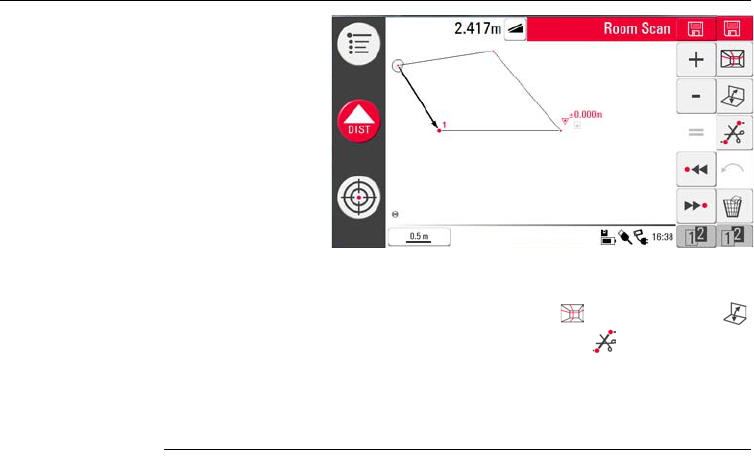
5. For further measurements proceed as described in "6.3 Measurement Workflow".
Please note that Tool bar changed.
Please note that three keys in the Tool Bar changed: for scan functions,
to switch between view and measuring perspektives and to clear lines
between points.
4. Reference height
is displayed in the
sketch area.
Different to the standard measuring mode single points without line
connection can be measured and cleared.
3D Disto, Software Applications 125
7.4.2 Unfold Mode
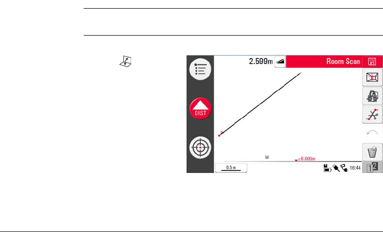
Description The Room Scan allows to switch the view of the sketch area from foot print to face
mode. This option is active when a line connection is available.
Unfold mode step-
by-step
1. Select a horizontal line between two points.
3. All measured points of the vertical plane are displayed.
4. To measure details or wall dimension proceed as described in "6.3 Measurement
Workflow".
2. Press . Sketch area
changes from foot
print to face view.
126
3D Disto, Software Applications
5. When measurements are finished, switch to foot print view by pressing again
to unlock.
A line of an automatically generated scan line can be unfolded as well.
3D Disto, Software Applications 127
7.4.3 Auto Shapes
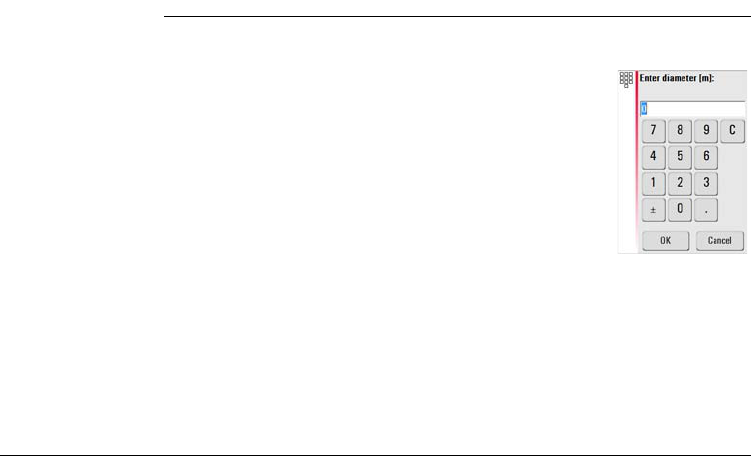
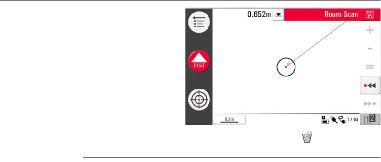
Circle tool The circle tool’s purpose is mainly to draw a circle on points like plugs or holes.
1. Target and measure a point and activate circle function by
long tip on the point in the sketch area. Pop-up opens Enter
diameter. OK/Cancel.
128
3D Disto, Software Applications
3. To clear the circle, enter 0 as value for diameter or press .
4. The result window contains radius, circumference and area of the circle.
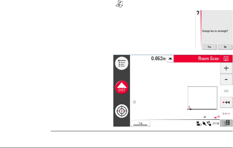
Rectangle tool This tool only works when changing the perspective to face mode and allows to
measure a diagonal and change it to a rectangle, for example to measure windows.
2. Enter the value and
press OK. Circle is
drawn around the
chosen point.
3D Disto, Software Applications 129
1. Go to 2nd tool bar, press to change perspective to face view.
2. Measure a diagonal of a rectangle, for example a window,
and activate the Rectangle Tool by long click on the line.
Pop-up prompts Change line to rectangle? Yes/No.
3. Diagonal changes to a
levelled rectangle.
130
3D Disto, Software Applications
7.4.4 Automated Profile Room Scan
Description This tool allows automated horizontal or vertical measurements on any surfaces.
Room Scan,
Start step-by-step
1. Press Menu » Applications » Room Scan.
2. Pop-up prompts to enter and measure reference height. Enter the value and
press OK.
3. Viewfinder opens. Target the reference height* and press .
4. Press in 2nd tool bar to start scan.
* Except for continuing existing measurements, for example relocation where
reference height is neglected.
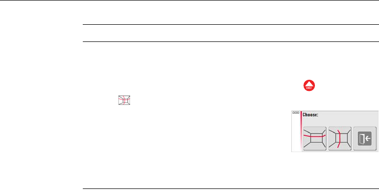
5. Pop-up prompts to select horizontal
or vertical scan.
3D Disto, Software Applications 131
Room Scan,
Horizontal Scan
step-by-step
1. Viewfinder opens to target and measure start point.
3. If you choose from ... to Viewfinder opens to measure scan end point.
Press .
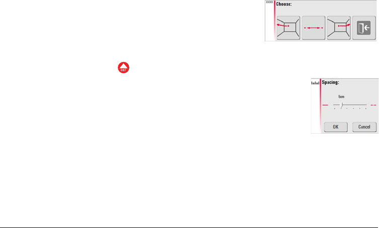
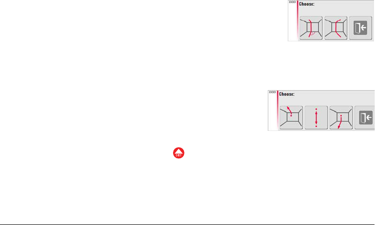
2. Pop-up prompts to define scan direction right
/ from ... to / left. Right for 360° clockwise,
between for a defined interval, left for 360°
scan counter clockwise. Choose one of these
options to go on.
4. Pop-up prompts to define spacing of the measurement.
Choose an intervall and press OK.
To reach best scan results do not choose small intervals at long
distances.
132
3D Disto, Software Applications
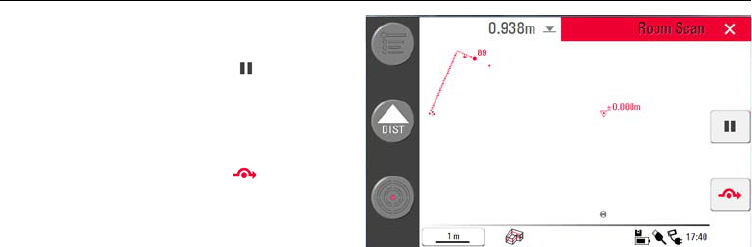
5. Press OK. Scan starts.
Tool bar changes.
6. Press to change
scan spacing, skip the
rest of the scan,
continue scan or cancel
scan.
7. Press to skip a scan
point that you do not
need or that causes
problems.
3D Disto, Software Applications 133
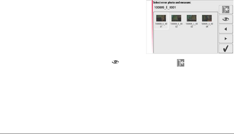
8. If any points could not be measured: pop-up prompts Scan not complete. View
report? Yes/No.
10. Select photo and press to view error point. Press to exit the gallery.
11. If No: pop-up prompts Scan completed.
9. If Yes: photo gallery with error
points opens.
134
3D Disto, Software Applications
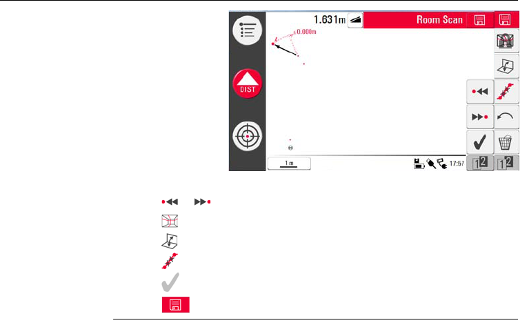
13. If Yes: New tool bar appears.
Press or to select points.
Press to start another scan in this measurement file.
Press to change view and measure for example some wall details.
Press to start a scan simplification that clears aligned points automatically.
Press to finish the scan.
14. Press to save and close measurment file.
12. If gallery is closed
or scan finished
and all points are
measured without
any error: pop-up
prompts Ready.
Edit Scan?
Yes/No?.
3D Disto, Software Applications 135
Room Scan,
Vertical scan step-
by-step
1. Viewfinder opens to target and measure start point.
• Orthogonal to Wall
1. If you choose orthogonal to wall 3D Disto measures the surface around the
measured start point automatically. Await the next pop-up.
3. If you choose from ... to Viewfinder opens to measure end point before spacing
can be defined. Press .
4. 3D Disto starts scan at the start point. Proceed as described in "Room Scan, Hori-
zontal Scan step-by-step", page 131 ff.
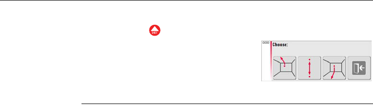
2. Pop-up prompts to choose scan orientation:
orthogonal to wall or free.
2. Pop-up prompts to define measurement direc-
tion up / from ... to / down followed by
spacing of measurement points.
136
3D Disto, Software Applications
• Free Profile
1. For a free profile Viewfinder opens to target and measure a point on the oppo-
site wall. Press .
3. Proceed as described in "Room Scan, Horizontal Scan step-by-step", page 131 ff.
2. Pop-up prompts to define measurement direc-
tion up / from ... to / down followed by
spacing of measurement points. If you choose
from ... to 3D Disto starts scan at the start
point.
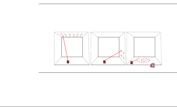
3D Disto, Software Applications 137
7.5 Projector
General The application projects points or geometrical grids onto a horizontal, vertical or
slope (= “free”) plane. Design data in DXF format can be imported or a grid’s geom-
etry can be entered manually.
It is ideal to project grid points to install suspended ceilings.
3D Disto_049
138
3D Disto, Software Applications
7.5.1 Workflow
Projector,
Start step-by-step
1. Press Menu » Applications » Projector.
2. Pop-up appears Sketch is cleared! OK/Cancel?.
3. Viewfinder opens to measure the reference area and details on which the grid
shall be projected.
4. Measure your reference area and press to finish measurement.
5. Pop-up prompts to Measure further reference points? Yes/No?.
6. If Yes: Viewfinder opens to measure other points of interest inside or beyond
the working area. When all points are measured go on with .
Pop-up will only appear if a measurement file is still open.
The 3D Disto assumes the measured reference area as a flat surface.
Bending or male faces lead to wrong measurements and layouts.
Ensure the 3D Disto will not be moved unintentionally, for example by a
bump. Otherwise all following measuring or grid points will not fit any more
to the geometry of the previous ones. Start a Location Check to sustain the
actual accuracy/geometry.
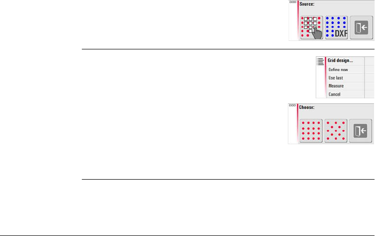
3D Disto, Software Applications 139
Projector,
Grid Mode step-by-
step
3. For using last grid: last grid is used for projection.
7. If No: pop-up prompts to choose between
Grid or DXF mode.
Grid Mode: Manual definition of grids to be
laid out.
1. Pop-up appears to choose between Define
new grid, Use last grid or Lock onto
existing grid.
2. For a new grid pop-up prompts to enter
column and row spacing and then to choose if
horizontal or vertical shift of row or column is
needed.
Column and row spacing must be at least >10 cm.
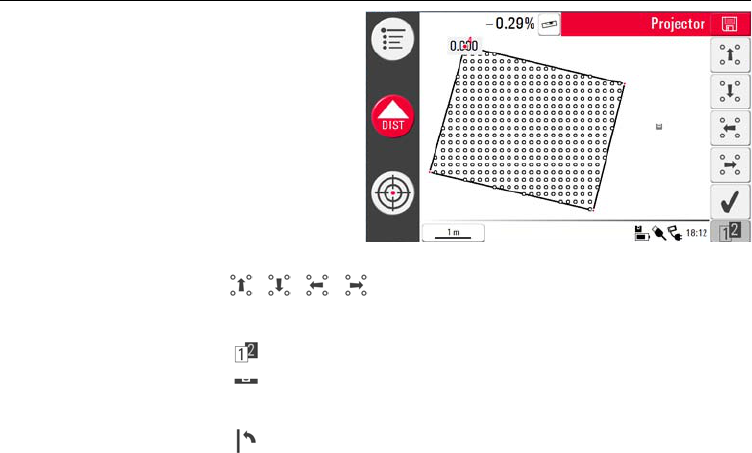
140
3D Disto, Software Applications
Projector,
Aligner step-by-
step
2. Each point and line can be selected by fingertip or pen.
3. With / / / the grid can be moved up, down, left and right on the
screen in small steps. The orthogonal distance of a selected grid point to a refer-
ence line is displayed. Tip on this distance to enter a value.
4. Press to find further grid alignment tools.
5. Press to adjust the grid horizontally.
6. Press to align grid parallel to a selected line.
1. Aligner opens with
measured reference
area including grid
points. Tool Bar
changes. The water
level icon in the Result
Bar stands for the tilt
of the projection plane.
This tool is only offered on walls and if the Tilt Sensor is enabled.
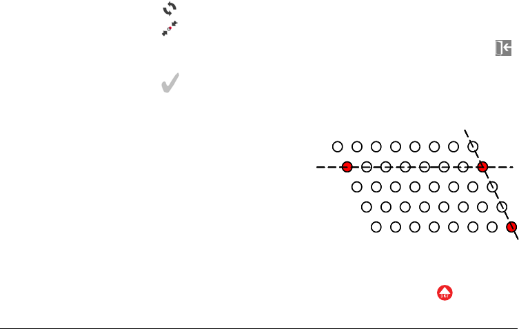
3D Disto, Software Applications 141
7. Press to turn the grid 90°.
8. Press to place the grid exactly on a reference point.
9. To measure further reference points or to go back to the Aligner tool press .
Proceed as described in 1. to 3.
10. Press to confirm the grid and close the aligner.
To lock onto existing grid:
4. Pop-up prompts to define 2nd axis. Choose between measuring P3 or enter
space for an orthogonal axis.
If measuring P3 Viewfinder opens to target and measure with .
1. Viewfinder opens to measure and
enter for grid and stationing:
2. Target and measure P1 and P2 of the
main axis.
Both points must be in one line
and far apart.
3. Pop-up appears to enter the number
of grid points between P1 and P2.
Confirm with OK.
P3 must be in column with P1 and far apart, as shown in illustration.
11
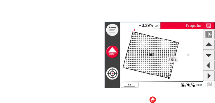
142
3D Disto, Software Applications
5. If you choose enter space pop-up prompts to enter the number of grid points
between P1 and P3.
6. The grid geometry is displayed in a pop-up.
8. Being in layout mode the tool bar changes and you can start to project the grid.
Use the arrow keys to select a point and press .
7. If grid ok, choose yes
and layout mode
starts.
If grid not ok proceed
as described in 2. to 7.
Perforated, structured or rough surfaces cause problems if the laser beam
can not reach the exact position of the layout point.
You can also select points by fingertip on point in screen or using the
Remote Control.
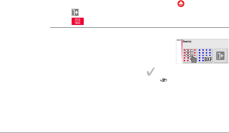
3D Disto, Software Applications 143
9. Laser point blinks if the exact position is found. Point is highlighted in red in
sketch area.
To layout further points select another point and press .
10. Press to go back to the Aligner tool.
11. Press to save file, for example for export data.
Projector,
DXF Mode step-by-
step
Allows to import a drawing, select a point and lays it out on an area.
2. File Manager opens, select file and press .
3. 3D Disto checks and prepares the file.
4. After successful import aligner opens and reference area and DXF data are
displayed.
1. Measure reference area and points as
described before and choose DXF option.
You can check the import file by pressing before import.
Avoid unnecessary data in the imported DXF file. There will be no layer
selection and only points of lines are imported (not the lines). Only 2D-
information is imported (+X/+Y is read as +Y/+X (+EAST/+NORTH)).

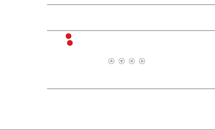
3D Disto, Software Applications 145
7.5.2 Targeting and Layout with RM100 Remote Control
Description The functionality of the RM100 Remote Control is like in standard measurement
during the whole projector application. The RM100 Remote Control only works if the
Control Unit is ON - otherwise measurement errors could not be displayed and
avoided.
Functionality of
the keys
Red key :
• Press to measure a point within the reference area. The 3D Disto searches
the closest grid point and projects it.
Short key press (<1sec.) on / / / :
• Each arrow key selects the neighbouring point, turns the 3D Disto and starts the
iterative measurement 1 second after key press.
• Several key presses on the same arrow key allow to skip neighbouring points. The
3D Disto starts to turn 1 second after the last key press.
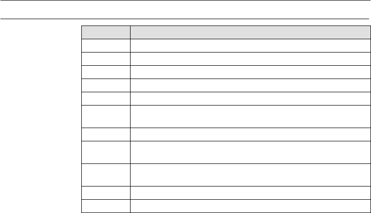
146
3D Disto, Error Messages
8 Error Messages
Error messages and
their meanings Error no. Meaning
150 Working range was exceeded.
151 Invalid measurement.
160 Repeat and do not move the ruler between both measurements.
170 Restart 3D Disto if the problem persists.
171 Check all devices, for example power supply, or cables, and try again.
240 Tilt sensor calibration was not successful. System accuracy is at risk.
Please contact your dealer.
241 Too much drift. Repeat calibration precisely.
242 3D Disto must be levelled precisely. Make stable setup. Repeat cali-
bration.
243 Make stable setup. Do not touch or rotate the sensor. Repeat calibra-
tion.
300 Select a horizontal line.
350 Check projection surface. Laser could not reach the correct position.

3D Disto, Error Messages 147
755 Point can not be measured. Try other position. Tool does not work on
horizontal planes.
760 Point can not be measured. Enter other values. Tool does not work
on horizontal planes.
765 Point can not be measured. Try other position or enter other value.
Tool does not work on horizontal planes.
800 Data import or export is not possible.
801 Not enough memory on USB stick.
802 Storage device does not work properly.
900 Sensor error. Contact your distributor or Leica Geosystems repre-
sentative if the error repeats.
950 Execute Station Check to keep accuracy!
952 Check sensor and blockings or move towards sensor.
953 Check connection and cable.
954 Plug in cable or choose "Wireless Connection" in the menu.
999 Please contact your distributor or Leica Geosystems representative.
Error no. Meaning

148
3D Disto, Check & Adjust
9 Check & Adjust
9.1 Overview
Description Leica Geosystems instruments are manufactured, assembled and adjusted to the
best possible quality and precision. Quick temperature changes, shock or stress can
cause deviations and decrease the instrument accuracy. It is therefore recommended
to check and adjust the instrument from time to time. This can be done on the site
by running through specific measurement procedures. The procedures are guided
and have to be followed carefully and precisely as described in the following chap-
ters.
Electronic
adjustment
The following instrument errors can be checked and adjusted electronically:
• Crosshair offset
• V-index and
• Tilt sensor.
Every angle measured in the daily work is corrected automatically if the tilt sensor is
activated and the 3D Disto is set up between 0° and 3°.
All calibration settings can also be reset to factory default.

3D Disto, Check & Adjust 149
During the manufacturing process, the instrument errors are carefully determined
and set to zero. As mentioned above, these errors can change and it is highly recom-
mended to redetermine them in the following situations:
• After rough or long transportations
• After long storage periods
• If the temperature difference between current environment and the temperature
at the last calibration is more than 20°C.
Tilt Sensor must be ON to detect unintended movements while the calibration is
running. After the calibration the tilt sensor is set to the previous state. Previously
running application must be closed.
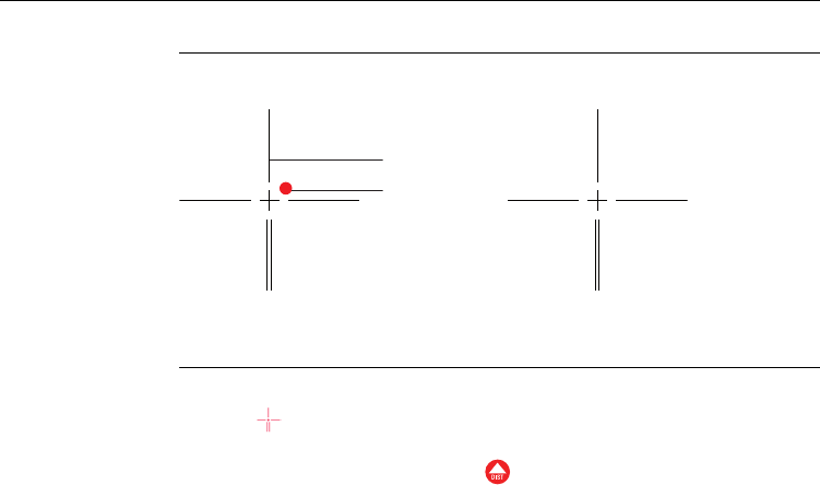
150
3D Disto, Check & Adjust
9.2 Cross Hair Offset
Problem The laser point and the cross hair in the Viewfinder do not coincide.
Adjustment step-
by-step
1. Calibration is started in Menu » Device » Calibration.
2. Press .
3. Viewfinder opens. Place a target mark in >25 m distance. Now aim the target
mark as precisely as possible. Press if the red laser spot is exactly on the
target.
Before calibration: After calibration:
a) Cross hair
b) Laser spot
3D Disto_029
a
b
3D Disto_030

3D Disto, Check & Adjust 151
4. Viewfinder stays open and red blinking cross hair is displayed. Move cross hair by
arrow keys to meet centre of target mark as precisely as possible. Press
again.
5. If in tolerance, pop-up appears with Correction = XXX gon. Set/Reset to
factury default or Cancel.
6. Choose Set or Reset to adjust cross hair. Final pop-up asks Are you sure?
Yes/Cancel.
7. If Yes checkmark is displayed in screen and confirms successful set of parame-
ters.
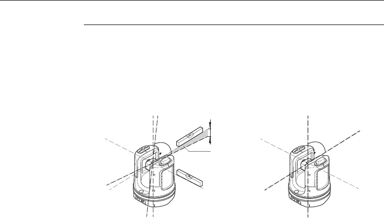
152
3D Disto, Check & Adjust
9.3 V-Index Error
Problem The vertical index does not coincide with the standing axis.
This can be detected when the heights or height differences of measured points
seem not to be correct; for example Tool Kit measurements do not work properly.
Tilt Sensor calibration is recommended before starting V-Index calibration!
Refer to "9.4 Tilt Sensor Calibration".
Before calibration: After calibration:
a) Height error
b) Vertical angle offset
3D Disto_031
a
b
3D Disto_032
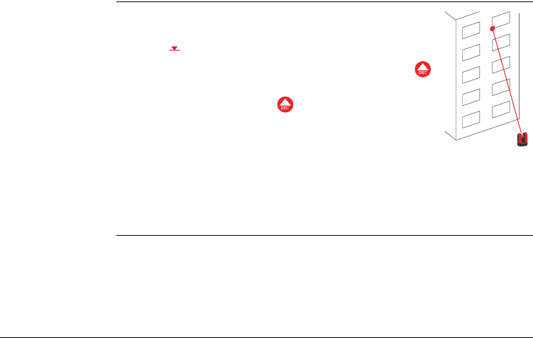
3D Disto, Check & Adjust 153
Adjustment step-
by-step
6. If both measurements were successful a pop-up appears with Correction =
XXX gon. Set/Reset to factury default or Cancel.
7. Choose Set or Reset to adjust V-index. Final pop-up asks Are you sure?
Yes/Cancel.
8. If Yes checkmark is displayed. This confirms successful set of parameters.
1. Setup the 3D Disto close to a wall with a steep target of good
visibility that is at least 15 m above the sensor.
2. Press .
3. Viewfinder opens. Target as precisely as possible. Press .
4. 3D Disto turns to second face automatically.
5. Target a second time. Press .
3D Disto_051
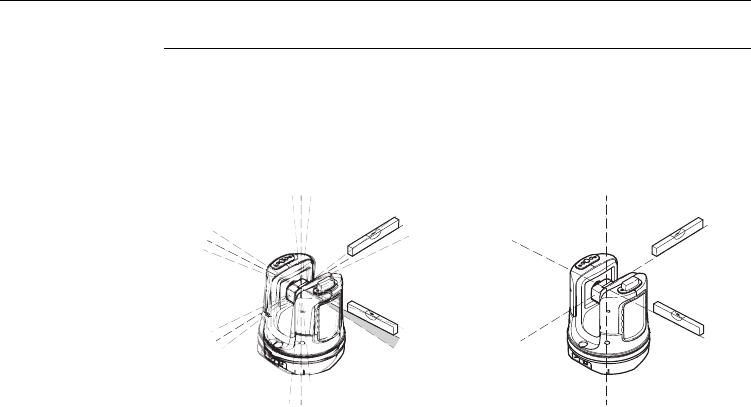
154
3D Disto, Check & Adjust
9.4 Tilt Sensor Calibration
Problem A tilt sensor error has the same impact as the V-index error but is depending on the
orientation.
This can be detected when the heights or height differences of measured points
seem not to be correct; for example Go to Horizon turn command does not work
properly.
Before calibration: After calibration:
a) Tilt sensor offset
3D Disto_033
3D Disto_034

3D Disto, Check & Adjust 155
This calibration is done automatically. You just have to ensure that the 3D Disto is
set up horizontally.
Adjustment step-
by-step
1. Press .
2. 3D Disto starts self-levelling: the tilt is checked and the instrument levels itself if
the tilt is <3°. Pop-up prompts Setup OK. Don't touch 3D Disto about 1
minute!
3. If ok pop-up appears Calibration successful.

156
3D Disto, Check & Adjust
9.5 Reset to Factory Settings
Reset to factory
settings step-by-
step
1. Press .
2. Pop-up appears Reset all calibration settings to factory default? Yes/No.

3D Disto, Instrument Protection (Theft Protection) 157
10 Instrument Protection (Theft Protection)
Description The instrument can be protected by a PIN. If the PIN protection is activated, the
Control Unit will always prompt for a PIN code entry after starting up. If a wrong PIN
has been typed in three times, a PUK is required which can be found on the instru-
ment delivery papers. If the PUK code was entered correctly, the PIN code is set to
default value "0" and the PIN protection is deactivated.
In case you lost the PUK code please contact your Leica Geosystems representative.
Activate PIN code
step-by-step
1. Startup Control Unit as described in "5 Instrument Setup".
2. Go to Menu » Device » Theft Protection. Default setting is Off.
3. Press On for activation.
4. Enter your desired personal PIN Code (3 to 8 character numeric or letters).
5. Accept with Ok.
Now the instrument is protected against unauthorised use. After switching on the
instrument, de-activate standby or re-enter in the PIN settings the PIN code entry is
necessary.

158
3D Disto, Instrument Protection (Theft Protection)
Deactivate PIN
code step-by-step
1. Startup Control Unit as described in "5 Instrument Setup".
2. Go to Menu » Device » Theft Protection.
3. Enter your personal PIN and press OK to accept.
4. Press Off for deactivation.
Now the instrument is not protected anymore against unauthorised use.

3D Disto, Care and Transport 159
11 Care and Transport
11.1 Transport
Transport in the
field
When transporting the equipment in the field, always make sure that you
• either carry the product in its original transport container,
• or carry the tripod with its legs splayed across your shoulder, keeping the
attached product upright.
Transport in a road
vehicle
Never carry the product loose in a road vehicle, as it can be affected by shock and
vibration. Always carry the product in its transport container and secure it.
Shipping When transporting the product by rail, air or sea, always use the complete original
Leica Geosystems packaging, transport container and cardboard box, or its equiva-
lent, to protect against shock and vibration.
Shipping, transport
of batteries
When transporting or shipping batteries, the person in charge of the product must
ensure that the applicable national and international rules and regulations are
observed. Before transportation or shipping, contact your local passenger or freight
transport company.
Field adjustment After transport inspect the field adjustment parameters given in this user manual
before using the product.

160
3D Disto, Care and Transport
11.2 Storage
Product Respect the temperature limits when storing the equipment, particularly in summer
if the equipment is inside a vehicle. Refer to "13 Technical Data" for information
about temperature limits.
Field adjustment After long periods of storage inspect the field adjustment parameters given in this
user manual before using the product.
Batteries • Alkaline and Li-Ion batteries
• Refer to "13 Technical Data" for information about storage temperature
range.
• A storage temperature range of 0°C to +20°C / +32°F to +68°F in dry environ-
ment is recommended to minimize self-discharging of the battery.
• At the recommended storage temperature range, batteries containing a 70%
to 100% charge can be stored for up to one year. After this storage period the
batteries must be recharged.
• After storage recharge batteries (Li-Ion) before using.
• Protect batteries from damp and wetness. Wet or damp batteries must be
dried before storing or use.

3D Disto, Care and Transport 161
11.3 Cleaning and Drying
Lens and housing
of 3D Disto
• Blow dust off lens and housing.
• Never touch the glass with your fingers.
• Use only a clean, soft, lint-free cloth for cleaning. If necessary, moisten the cloth
with water or pure alcohol. Do not use other liquids; these may attack the
polymer components.
Damp products • Dry the product, the transport container, the foam inserts and the accessories
at a temperature not greater than 40°C / 104°F and clean them.
• Do not repack until everything is completely dry.
• Always close the transport container when using in the field.
Cables and plugs Keep plugs clean and dry. Blow away any dirt lodged in the plugs of the connecting
cables.

162
3D Disto, Safety Directions
12 Safety Directions
12.1 General
Description The following directions should enable the person responsible for the product, and
the person who actually uses the equipment, to anticipate and avoid operational
hazards.
The person responsible for the product must ensure that all users understand these
directions and adhere to them.

3D Disto, Safety Directions 163
12.2 Intended Use
Permitted use • 3D measuring of distance, heights, grades, angles, area and volume.
• Manual and automatic measurement of room dimensions.
• Automatic measurement of profiles.
• Laying out points and designs, for example from blueprint.
• Generation of drawings.
• Camera functionality.
• Import/Export of data.
• Administration of data.
Adverse use • Use of the product without instruction.
• Use outside of the intended limits.
• Disabling safety systems.
• Removal of hazard notices.
• Opening the product using tools, for example screwdriver, unless this is specifi-
cally permitted for certain functions.
• Modification or conversion of the product.
• Use of products with obviously recognizable damages or defects.
• Use with accessories from other manufacturers without the prior explicit
approval of Leica Geosystems.

164
3D Disto, Safety Directions
• Inadequate safeguards at the working site, for example when measuring on
roads or sites.
• Deliberate dazzling of third parties.
• Controlling of machines, moving objects or similar monitoring application without
additional control- and safety installations.
ƽWarning Adverse use can lead to injury, malfunction and damage.
It is the task of the person responsible for the equipment to inform the user about
hazards and how to counteract them. The product is not to be operated until the user
has been instructed on how to work with it.

3D Disto, Safety Directions 165
12.3 Limits of Use
Environment Suitable for use in an atmosphere appropriate for permanent human habitation: not
suitable for use in aggressive or explosive environments.
ƽDanger Local safety authorities and safety experts must be contacted before working in
hazardous areas, or in close proximity to electrical installations or similar situations
by the person in charge of the product.

166
3D Disto, Safety Directions
12.4 Responsibilities
Manufacturer of
the product
Leica Geosystems AG, CH-9435 Heerbrugg, hereinafter referred to as Leica Geosys-
tems, is responsible for supplying the product, including the user manual and original
accessories, in a completely safe condition.
Manufacturers of
non Leica
Geosystems
accessories
The manufacturers of non Leica Geosystems accessories for the product are respon-
sible for developing, implementing and communicating safety concepts for their
products, and are also responsible for the effectiveness of those safety concepts in
combination with the Leica Geosystems product.
Person in charge of
the product
The person in charge of the product has the following duties:
• To understand the safety instructions on the product and the instructions in the
user manual.
• To be familiar with local regulations relating to safety and accident prevention.
• To inform Leica Geosystems immediately if the product and the application
becomes unsafe.
ƽWarning The person responsible for the product must ensure that it is used in accordance with
the instructions. This person is also accountable for the training and the deployment
of personnel who use the product and for the safety of the equipment in use.

3D Disto, Safety Directions 167
12.5 Hazards of Use
ƽWarning The absence of instruction, or the inadequate imparting of instruction, can lead to
incorrect or adverse use, and can give rise to accidents with far-reaching human,
material, financial and environmental consequences.
Precautions:
All users must follow the safety directions given by the manufacturer and the direc-
tions of the person responsible for the product.
ƽCaution Watch out for erroneous measurement results if the product has been dropped or
has been misused, modified, stored for long periods or transported.
Precautions:
Periodically carry out test measurements and perform the field adjustments indicated
in the user manual, particularly after the product has been subjected to abnormal use
and before and after important measurements.
ƽWarning During dynamic applications, for example layout procedures there is a danger of acci-
dents occurring if the user does not pay attention to the environmental conditions
around, for example obstacles such as cables.
Precautions:
The person responsible for the product must make all users fully aware of the existing
dangers.

168
3D Disto, Safety Directions
ƽWarning Inadequate securing of the working site can lead to dangerous situations, for
example in traffic, on building sites, and at industrial installations.
Precautions:
Always ensure that the working site is adequately secured. Adhere to the regulations
governing safety and accident prevention and road traffic.
ƽCaution If the accessories used with the product are not properly secured and the product is
subjected to mechanical shock, for example blows or falling, the product may be
damaged or people may sustain injury.
Precautions:
When setting-up the product, make sure that the accessories are correctly adapted,
fitted, secured, and locked in position.
Avoid subjecting the product to mechanical stress.
ƽCaution During the transport, shipping or disposal of batteries it is possible for inappropriate
mechanical influences to constitute a fire hazard.
Precautions:
Before shipping the product or disposing of it, discharge the batteries by running the
product until they are flat.
When transporting or shipping batteries, the person in charge of the product must
ensure that the applicable national and international rules and regulations are
observed. Before transportation or shipping contact your local passenger or freight
transport company.

3D Disto, Safety Directions 169
ƽWarning Using a battery charger not recommended by Leica Geosystems can destroy the
batteries. This can cause fire or explosions.
Precautions:
Only use chargers recommended by Leica Geosystems to charge the batteries.
ƽWarning High mechanical stress, high ambient temperatures or immersion into fluids can
cause leackage, fire or explosions of the batteries.
Precautions:
Protect the batteries from mechanical influences and high ambient temperatures. Do
not drop or immerse batteries into fluids.
170
3D Disto, Safety Directions
ƽWarning Flat batteries must not be disposed of with household waste. Care for the environ-
ment and take them to the collection points provided in accordance with national or
local regulations.
If the product is improperly disposed of, the following can happen:
• If polymer parts are burnt, poisonous gases are produced which may impair
health.
• If batteries are damaged or are heated strongly, they can explode and cause
poisoning, burning, corrosion or environmental contamination.
• By disposing of the product irresponsibly you may enable unauthorised persons
to use it in contravention of the regulations, exposing themselves and third
parties to the risk of severe injury and rendering the environment liable to
contamination.
• Improper disposal of silicone oil may cause environmental contamination.
Precautions:
Product specific treatment and waste management information can be downloaded
from the Leica Geosystems home page at http://www.leica-geosystems.com/treat-
ment or received from your Leica Geosystems dealer.
The product must not be disposed with household waste.
Dispose of the product appropriately in accordance with the national
regulations in force in your country.
Always prevent access to the product by unauthorised personnel.

3D Disto, Safety Directions 171
ƽWarning Only Leica Geosystems authorised service workshops are entitled to repair these
products.

172
3D Disto, Safety Directions
12.6 Laser Classification
Integrated
distancemeter
The Leica 3D Disto produces a visible laser beam which emerges from the front of
the instrument.
It is a Class 2 laser product in accordance with:
• IEC60825-1 : 2007 "Radiation safety of laser products"
Laser Class 2 products:
Do not stare into the laser beam or direct it towards other people unnecessarily.
Eye protection is normally afforded by aversion responses including the blink reflex.
ƽWarning Looking directly into the beam with optical aids (e.g. binoculars, telescopes) can be
hazardous.
Precautions:
Do not look directly into the beam with optical aids.
ƽCaution Looking into the laser beam may be hazardous to the eyes.
Precautions:
Do not look into the laser beam. Make sure the laser is aimed above or below eye
level. (particularly with fixed installations, in machines, etc.)
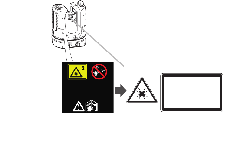
3D Disto, Safety Directions 173
Labelling
a) Laser beam
a
Complies with 21 CFR 1040.10 and
1040.11 except for deviations
pursuant to Laser Notice Nr. 50,
dated June 24, 2007
>1/4s
3D Disto_041
Laser Radiation
Do not stare into the beam
Class 2 Laser Product
according to IEC 60825-1
( 2007-03 )
Po 1.00 mW
= 620 - 690 nm

174
3D Disto, Safety Directions
12.7 Electromagnetic Compatibility EMC
Description The term Electromagnetic Compatability is taken to mean the capability of the
product to function smoothly in an environment where electromagnetic radiation and
electrostatic discharges are present, and without causing electromagnetic distur-
bances to other equipment.
ƽWarning The 3D Disto conforms to the most stringent requirements of the relevant standards
and regulations.
Yet, the possibility of it causing interference in other devices cannot be totally
excluded.
ƽCaution Never attempt to repair the product yourself. In case of damage, contact the local
dealership.
ƽWarning Electromagnetic radiation can cause disturbances in other equipment.
Although the product meets the strict regulations and standards which are in force
in this respect, Leica Geosystems cannot completely exclude the possibility that other
equipment may be disturbed.
ƽCaution There is a risk that disturbances may be caused in other equipment if the product is
used in conjunction with accessories from other manufacturers, for example field

3D Disto, Safety Directions 175
computers, personal computers, two-way radios, non-standard cables or external
batteries.
Precautions:
Use only the equipment and accessories recommended by Leica Geosystems. When
combined with the product, they meet the strict requirements stipulated by the
guidelines and standards. When using computers and two-way radios, pay attention
to the information about electromagnetic compatibility provided by the manufac-
turer.
ƽCaution Disturbances caused by electromagnetic radiation can result in erroneous measure-
ments.
Although the product meets the strict regulations and standards which are in force
in this respect, Leica Geosystems cannot completely exclude the possibility that the
product may be disturbed by very intense electromagnetic radiation, for example,
near radio transmitters, two-way radios or diesel generators.
Precautions:
Check the plausibility of results obtained under these conditions.
ƽWarning If the product is operated with connecting cables attached at only one of their two
ends, for example external supply cables, interface cables, the permitted level of

176
3D Disto, Safety Directions
electromagnetic radiation may be exceeded and the correct functioning of other
products may be impaired.
Precautions:
While the product is in use, connecting cables, for example product to external
battery, product to computer, must be connected at both ends.
Work with WLAN
ƽWarning Electromagnetic fields can cause disturbances in other equipment, in installations, in
medical devices, for example pacemakers or hearing aids and in aircraft. It can also
affect humans and animals.
Precautions:
Although the product meets in combination with radio or digital cellular phone
devices recommended by Leica Geosystems the strict regulations and standards
which are in force in this respect, Leica Geosystems cannot completely exclude the
possibility that other equipment may be disturbed or that humans or animals may be
affected.
• Do not operate the product in the vicinity of filling stations or chemical installa-
tions, or in other areas where an explosion hazard exists.
• Do not use the product near medical to equipment.
• Do not operate the product in aircraft.
• Do not use the product near your body for extended periods.

3D Disto, Safety Directions 177
12.8 FCC Statement, Applicable in U.S.
ƽWarning This equipment has been tested and found to comply with the limits for a Class B
digital device, pursuant to part 15 of the FCC rules.
These limits are designed to provide reasonable protection against harmful interfer-
ence in a residential installation.
This equipment generates, uses and can radiate radio frequency energy and, if not
installed and used in accordance with the instructions, may cause harmful interfer-
ence to radio communications. However, there is no guarantee that interference will
not occur in a particular installation.
If this equipment does cause harmful interference to radio or television reception,
which can be determined by turning the equipment off and on, the user is encour-
aged to try to correct the interference by one or more of the following measures:
• Reorient or relocate the receiving antenna.
• Increase the separation between the equipment and the receiver.
• Connect the equipment into an outlet on a circuit different from that to which
the receiver is connected.
• Consult the dealer or an experienced radio/TV technician for help.
ƽWarning Changes or modifications not expressly approved by Leica Geosystems for compli-
ance could void the user's authority to operate the equipment.

178
3D Disto, Safety Directions
SAR Information FCC Radiation Exposure Statement
The radiated output power of the instrument is far below the FCC radio frequency
exposure limits. Nevertheless, the instrument should be used in such a manner that
the potential for human contact during normal operation is minimised. To avoid the
possibility of exceeding the FCC radio frequency exposure limits, you should keep a
distance of at least 20 cm between you (or any other person in the vicinity) and the
antenna that is built into the instrument.
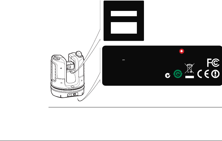
3D Disto, Safety Directions 179
Labelling 3D Disto
3D Disto_042
Type: Leica 3D Disto
Made in Singapore www.leica-geosystems.com
Art.No.: 772171
Power: 24V / 2.5A
Patents:
WO 9427164, WO0216964, US 5949531,
WO 0244754, EP 1195617, Wo 9818019
IC: 3177A-3DDISTO
FCC ID: RFF-3DDISTO
SWISS Technology
by Leica Geosystems
Equi.No.:
123456789012
S/N:
12345678
12345678
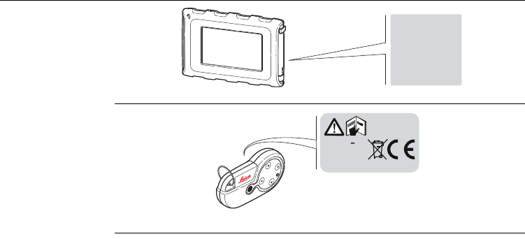
180
3D Disto, Safety Directions
Labelling Control
Unit
Labelling RM100
Remote Control
3D Disto_044
Art.No.: 123456
123456
S.No.: PC102302494
102302494
3D Disto_043
RM100
Type: RM100
Art.No.: 780994
Power: 1.5V / 0.4A
Leica Geosystems AG
CH-9435 Heerbrugg
Manufactured:
3D Disto, Safety Directions 181
12.9 Conformity to National Regulations
Conformity to
National
Regulations
•France
Concerning European Economic Area: The use of this WLAN product (or the WLAN
function of this product) is restricted to only indoor use in France.
• The conformity for countries with other national regulations not covered by the
FCC part 15 or European directive 1999/5/EC has to be approved prior to use and
operation
Hereby, Leica Geosystems AG, declares that the instrument is in
compliance with the essential requirements and other relevant
provisions of applicable European Directives. The declaration of
conformity may be consulted at http://www.leica-geosystems.com/ce.
182
3D Disto, Technical Data
13 Technical Data
Accuracy*
Working range
angle
measurement
Characteristics
laser
distancemeter
Viewfinder
Accuracy, at 20°C @ 10 m @ 30 m @ 50 m
Point Accuracy (3D) ± 1.0 mm ± 3.0 mm ± 5.0 mm
Horizontal angle: 360°
Vertical angle: 250°
Measuring system: System analyser basis 100 MHz - 150 MHz
Type: Coaxial, visible red laser
Working range: 0.5 - 50 m
Laser class: 2
Lasertype: 650 nm; < 1 mW
Ø Laser point (at distances): @ 10 m: ~7 mm x 7 mm
@ 30 m: ~9 mm x 15 mm
Zoom (Magnification): 1x, 2x, 4x, 8x
Field of view (@ 10 m): 1x: 3.40 m x 2.14 m
2x: 1.70 m x 1.07 m
4x: 0.85 m x 0.54 m
8x: 0.42 m x 0.27 m
3D Disto, Technical Data 183
Tilt sensor
Circular bubble
sensitivity
1°/mm
Operation
Self-levelling range: ± 3°
Type Description
Display High resolution screen, 800 x 480 Pixel, 4.8'' TFT LCD,
16 Mio Colour
Buttons/User interface 3D Disto: 1 ON/OFF button
Control Unit: Touchscreen, 1 ON/OFF button
Memory capacity Internal memory: 500 GB
Flash memory: 32 GB
Ports 3D Disto: USB Type B, Power supply plugin, power
supply plugin for Control Unit
Control Unit: USB Type A, Micro-B, power supply
plugin
184
3D Disto, Technical Data
Communication
Power
Mounting 5/8" thread
Instrument
dimensions
Type Description
Data transfer USB: Type Micro-B and Type A, WLAN
Wireless technology SD Card, Range 50 m (depending on the environment),
11 channels
Supported data formats Import: DXF
Export: DXF, TXT, CSV, JPG
Instrument Type Typical operating time
3D Disto Li-Ion battery, voltage: 14.4 V 63 Wh,
charging time 8 h
External power supply voltage: 24 VDC /
2.5 A
8 h
Control Unit Li-Ion battery, 2500 mAh, 3.7 V
External power supply voltage: 5 VDC /
2.0 A, charging time 7 h
6 h
3D Disto: Ø 186.6 x 215.5 mm
Control Unit: 178.5 x 120 x 25.8 mm
3D Disto, Technical Data 185
Weight
Environmental
specifications
Temperature
Protection against dust, sand and water
Humidity
3D Disto: 2.8 kg
Control Unit: 0.33 kg
Type Operating temperature [°C] Storage temperature [°C]
3D Disto -10 to +50 -25 to +70
Control Unit -10 to +50 -25 to +70
Type Protection
3D Disto IP54 (IEC 60529)
Control Unit IP5X
Type Protection
3D Disto Max. 85%r.h non condensing
Control Unit Max. 85%r.h non condensing

186
3D Disto, Technical Data
RM100 Remote
Control
Range: 50 m
Communication: Infrared (IR)
Battery 1 AA, 1.5 V
3D Disto, International Limited Warranty, Software License Agreement 187
14 International Limited Warranty, Software
License Agreement
International
Limited Warranty
This product is subject to the terms and conditions set out in the International
Limited Warranty which you can download from the Leica Geosystems home page at
http://www.leica-geosystems.com/internationalwarranty or collect from your Leica
Geosystems distributor. The foregoing warranty is exclusive and is in lieu of all other
warranties, terms or conditions, express or implied, either in fact or by operation of
law, statutory or otherwise, including warranties, terms or conditions of merchanta-
bility, fitness for a particular purpose, satisfactory quality and non-infringement, all
of which are expressly disclaimed.
* To receive the three year warranty, the product must be registered on our
website www.leica-geosystems.com/registration within eight weeks of the
purchase date. If the product is not registered, a two year warranty applies.
This product comes with a three* year warranty from Leica Geosystems.
More detailed information can be found at:
www.leica-geosystems.com/registration
All rights reserved for changes (drawings, descriptions and technical
specifications).

188
3D Disto, International Limited Warranty, Software License Agreement
Software License
Agreement
This product contains software that is preinstalled on the product, or that is supplied
to you on a data carrier medium, or that can be downloaded by you online pursuant
to prior authorisation from Leica Geosystems. Such software is protected by copy-
right and other laws and its use is defined and regulated by the Leica Geosystems
Software License Agreement, which covers aspects such as, but not limited to, Scope
of the License, Warranty, Intellectual Property Rights, Limitation of Liability, Exclusion
of other Assurances, Governing Law and Place of Jurisdiction. Please make sure, that
at any time you fully comply with the terms and conditions of the Leica Geosystems
Software License Agreement.
Such agreement is provided together with all products and can also be referred to
and downloaded at the Leica Geosystems home page at http://www.leica-geosys-
tems.com/swlicense or collected from your Leica Geosystems distributor.
You must not install or use the software unless you have read and accepted the
terms and conditions of the Leica Geosystems Software License Agreement. Installa-
tion or use of the software or any part thereof, is deemed to be an acceptance of all
the terms and conditions of such License Agreement. If you do not agree to all or
some of the terms of such License Agreement, you may not download, install or use
the software and you must return the unused software together with its accompa-
nying documentation and the purchase receipt to the dealer from whom you
purchased the product within ten (10) days of purchase to obtain a full refund of the
purchase price.

3D Disto, International Limited Warranty, Software License Agreement 189
GNU public license Parts of the 3D Disto software are developed under GPL (GNU public license). The
corresponding licenses can be found on the 3D Disto documentation CD in the direc-
tory GPL licenses. For obtaining more information, please search for contact at
www.leica-geosystems.com.

190
3D Disto, Index
Index
A
Abbreviations ...................................................... 13
Adjustment
Electronic ..................................................... 148
B
Battery
Charging ........................................................ 55
First-time use ................................................ 54
C
Care .................................................................. 159
Check & Adjust ................................................. 148
Cleaning and Drying .......................................... 161
Components
3D Disto ........................................................ 28
Control Unit ................................................... 32
RM100 Remote Control .................................. 33
Container contents ............................................. 26
D
Documentation .....................................................9
User Manual .....................................................9
E
Electromagnetic compatibility ............................174
Electronic adjustment ........................................148
Environmental specifications .............................185
F
FCC Statement ..................................................177
H
Hazards of use ..................................................167
How to use this manual ........................................9
I
Intended use .....................................................163
L
Laser
Classification ................................................172
Limits of use .....................................................165

3D Disto, Index 191
M
Manual
Description of manuals .................................... 9
How to use ...................................................... 9
Validity of user manual .................................... 9
O
Operating temperature ..................................... 185
P
Power supply
3D Disto ........................................................ 34
Control Unit ................................................... 35
RM100 Remote Control .................................. 37
R
Responsibilities ................................................. 166
S
Safety directions ............................................... 162
Screen ................................................................ 45
Storage ............................................................. 160
Storage temperature ........................................ 185
Symbols ................................................................ 3
T
Technical data ...................................................182
Technical terms ...................................................13
Temperature .....................................................185
Instrument
Operating ................................................185
Transport ..........................................................159
U
User interface .....................................................44
W
Weight ..............................................................185
Z
Zenith .................................................................16
Total Quality Management: Our commitment to total customer satisfaction.
Leica Geosystems AG, Heerbrugg, Switzerland, has been
certified as being equipped with a quality system which
meets the International Standards of Quality Management
and Quality Systems (ISO standard 9001) and Environmental
Management Systems (ISO standard 14001).
Ask your local Leica dealer for more information about our TQM program.
Patents:
WO 9427164
WO 0216964
US 5949531
WO 0244754
EP 1195617
WO 9818019
781120(CD)-0.9.0en
Original text
© 2010 Leica Geosystems AG, Heerbrugg, Switzerland
Leica Geosystems AG
Heinrich-Wild-Strasse
CH-9435 Heerbrugg
Switzerland
Phone +41 71 727 31 31
www.leica-geosystems.com