Leidos NORMARC7050 NORMARC 7050 User Manual Normarc 7050 General Description
Lockheed Martin Air Traffic Management NORMARC 7050 Normarc 7050 General Description
Leidos >
Contents
7050 General Description

©1999 Navia Aviation AS
NORMARC 7050
MARKER BEACON
General Description

©1999 Navia Aviation AS
©1999 Navia Aviation AS 21464-5 GENERAL INFORMATION
USER MANUALNORMARC 7050
MARKER BEACON
1-1
PART I INTRODUCTION
1 GENERAL INFORMATION
This paragraph gives a description of a typical ILS installation and the Normarc Marker Bea-
con system. Conventions and abbreviations used in this manual are also given.
1.1 Introduction
This is an overview of Normarc's NM 7050 ILS marker beacons systems.
1.1.1 ILS Overview
A complete Instrument Landing System comprises:
•A LOCALIZER SYSTEM, producing a radio course to furnish lateral guidance to the airport
runway.
• A GLIDE PATH SYSTEM, producing a radio course to furnish vertical guidance down the
correct descent angle to the runway.
• MARKER BEACONS, to provide accurate radio fixes along the approach course.
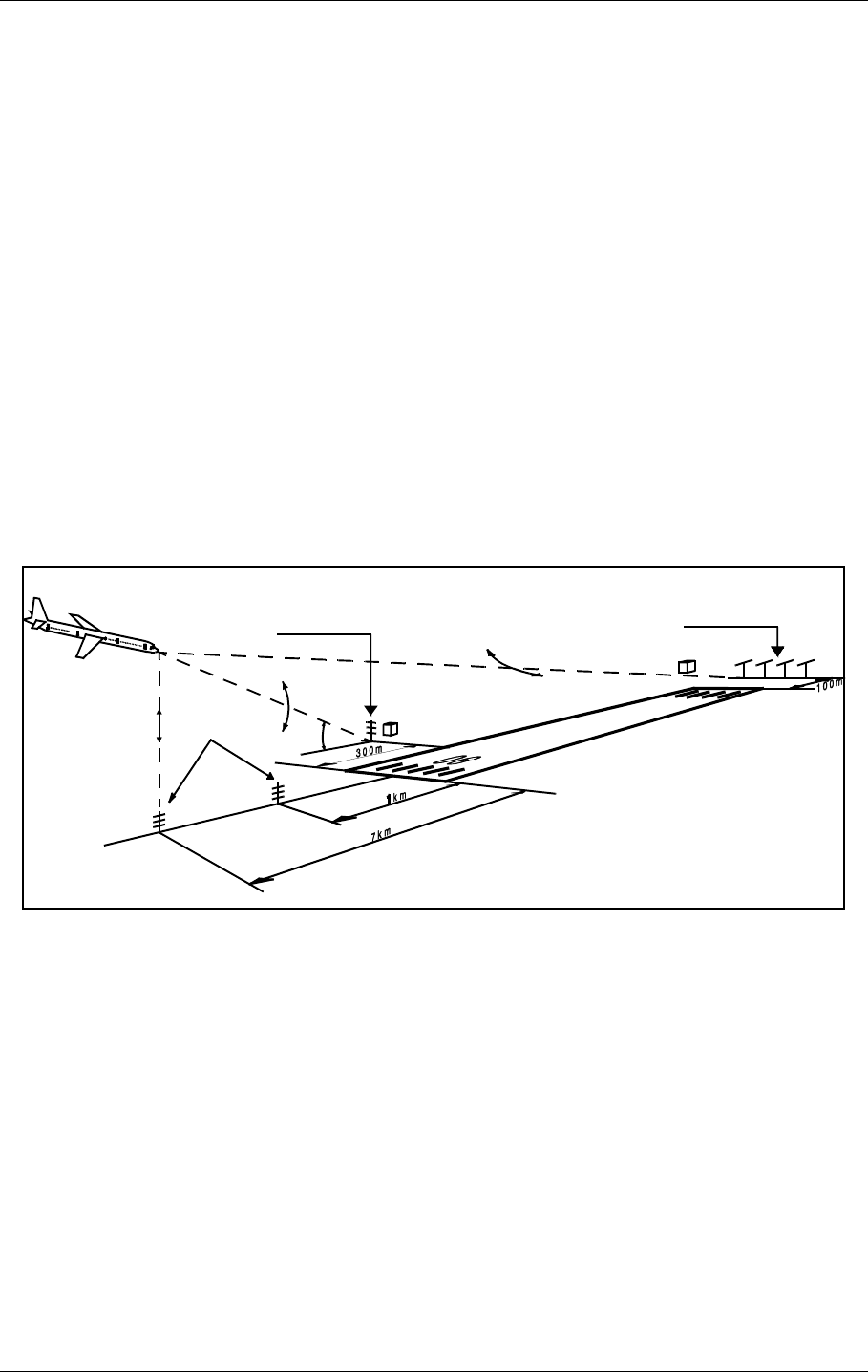
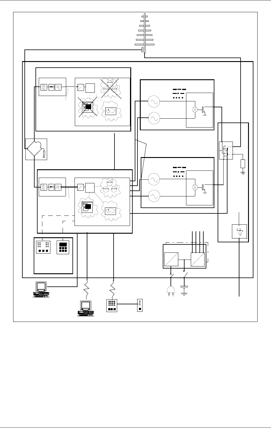
The layout of a typical ILS airport installation is shown below.
Figure 1-1Typical ILS airport installation
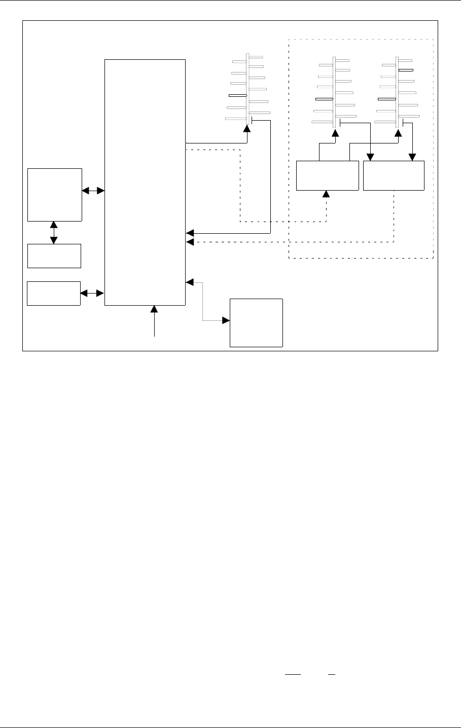
1.1.2 Marker Beacons Overview
The complete ILS marker beacons system comprises:
• A Marker Beacon transmitter/monitor cabinet
• A Marker Beacon antenna
• A remote control
• An Remote Maintenance Monitor (RMM) program to be installed on a PC
• Optional slave panel
• Optional backup battery
Localizer
110 MHz
Glide Path
330 MHz
Marker Beacon
75MHz
3°
HBK547-1
USER MANUAL
1-2
21464-5
NORMARC 7050
MARKER BEACON
GENERAL INFORMATION ©1999 Navia Aviation AS
Figure 1-2 Marker beacon block diagram
1.1.3 Marker Beacons Description
The marker beacons are located vertically beneath the localizer course line at distance 150m
(inner marker), 1km (middle marker) and 7km (outer marker) from the runway threshold.
The beacons radiate a 75MHz radio signal with an audio Morse code. The Morse code and
modulation frequency differ for the outer, middle and inner marker. Outer marker transmits
dash code 400Hz, middle marker transmits dash dot code 1300Hz and inner marker dot code
3000Hz.
1.2 Product Type Numbers
The Normarc product numbering system is based on the following three levels:
•System
• Assembly
• Module
Systems have type numbers starting with NM, for example NM7050. Systems consist of
assemblies, modules and parts.
Assemblies have type numbers consisting of three letters, a three- or four- digit number and a
letter, for example CAA 1370A. CAA is an abbreviation of CAbinet Assembly, 1370 is a run-
ning number, and the last letter is the variant designator. Assemblies can consist of assem-
blies, modules and parts.
REMOTE
CONTROL
UNIT
SLAVE
PANEL
RMM
SYSTEM
TRANSMITTERS
AND
MODULATORS
24V
BATTERY
MONITOR(S)
POWER
SUPPLY(S)
MAINS INPUT
220V/110V AC
BEACON
ANTENNA
MARKER
BEACON
CABINET
DISTRIBUTION
NETWORK
MONITOR
NETWORK
RF OUT
RF IN
DUAL ANTENNA SYSTEM
HBK779/1

©1999 Navia Aviation AS 21464-5 GENERAL INFORMATION
USER MANUALNORMARC 7050
MARKER BEACON
1-3
Modules have type numbers consisting of two letters, a three- or four- digit number and a let-
ter, for example MO 1374A. MO is an abbreviation of MOnitor, 1374 is a running number, and
the last letter is the variant designator. Modules consist of parts.
1.3 Abbreviations
AC :Alternating Current
ADC :Analog to Digital Converter
AGC :Automatic Gain Control
CPU :Central Processing Unit
DAC :Digital to Analog Converter
DC :Direct Current
DM :Depth of Modulation
EEPROM :Electrically Erasable Programmable Read Only Memory
EMC :Electro Magnetic Compatibility
EMI :Electro Magnetic Interference
EPROM :Erasable Programmable Read Only Memory
FIFO :First In First Out
FPGA :Field Programmable Gate Array
I/F :Inter Face
ILS :Instrument Landing System
IM :Inner Marker
LED :Light Emitting Diode
LF :Low Frequency
LRU :Line Replaceable Unit
MCU :Monitor Combiner Unit
MM :Middle Marker
NAV :NAVigation signals
NF :Near Field
OM :Outer Marker
PC :Personal Computer
RAM :Random Access Memory
RF :Radio Frequency
RMM :Remote Maintenance Monitor
RMS :Remote Monitoring System
ROM :Read Only Memory
RTC :Real Time Clock
SC :Station Control
SRAM :Static Random Access Memory
STB :STandBy
SW :Soft Ware
TX :Transmitter

©1999 Navia Aviation AS 21464-5 Physical organisation
USER MANUALNORMARC 7050
MARKER BEACON
2-1
2 Physical organisation
This chapter describes the physical outline of the NM 7050
2.1 Configurations
2.1.1 Module and Assembly Location
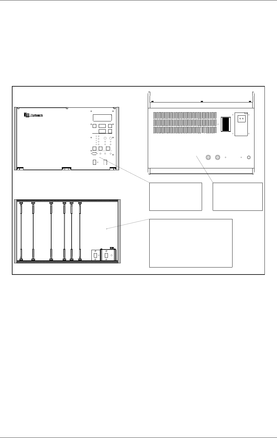
The figures on the following pages show the locations of the modules in the main cabinet.
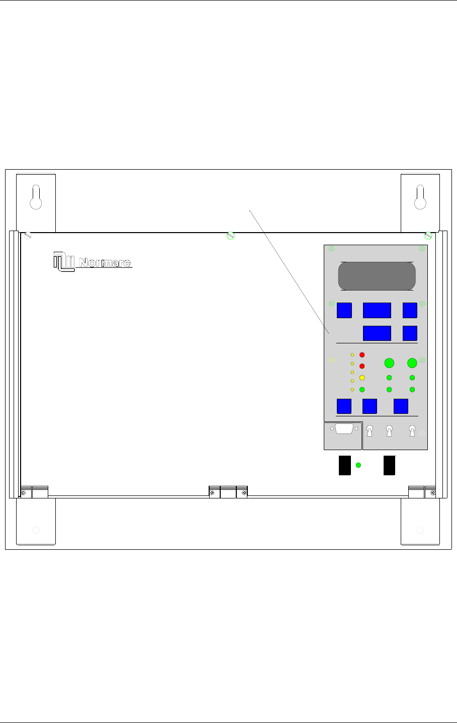
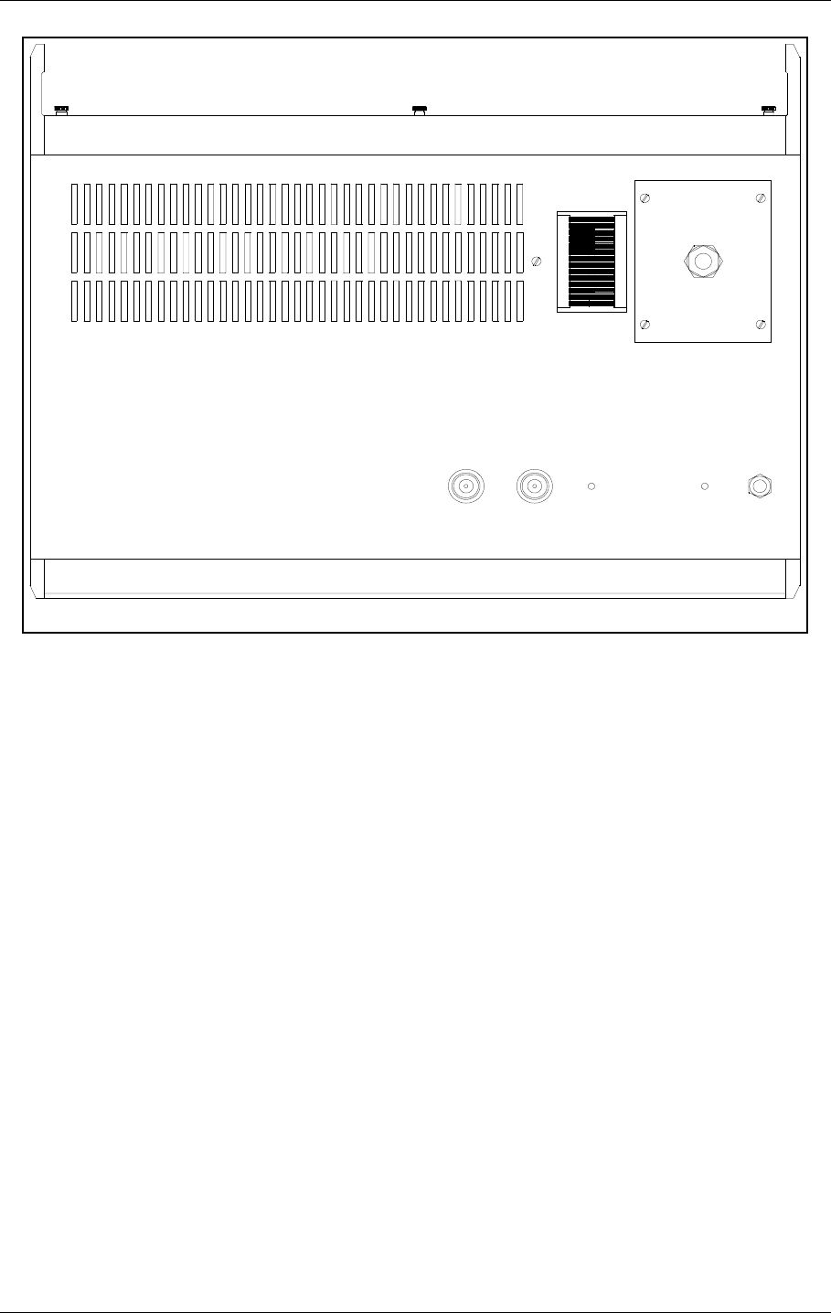
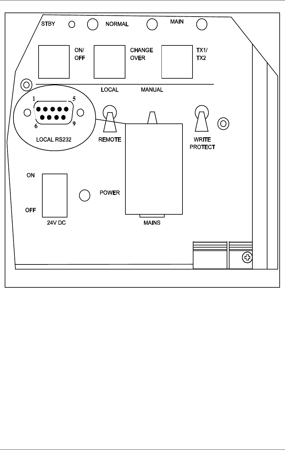
Figure 2-1 shows the front panel of the cabinet, with the control panel, on/off switch and local
PC connection.
Figure 2-1 NM 7050 Front panel
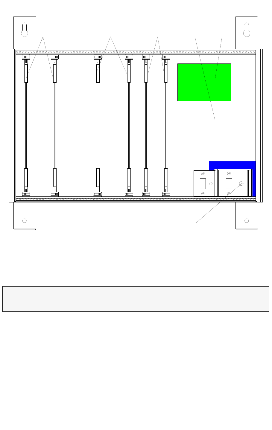
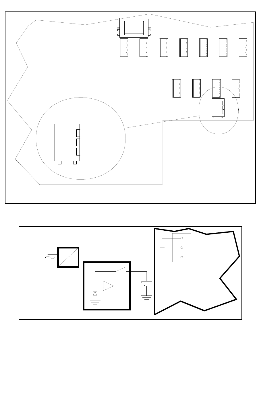
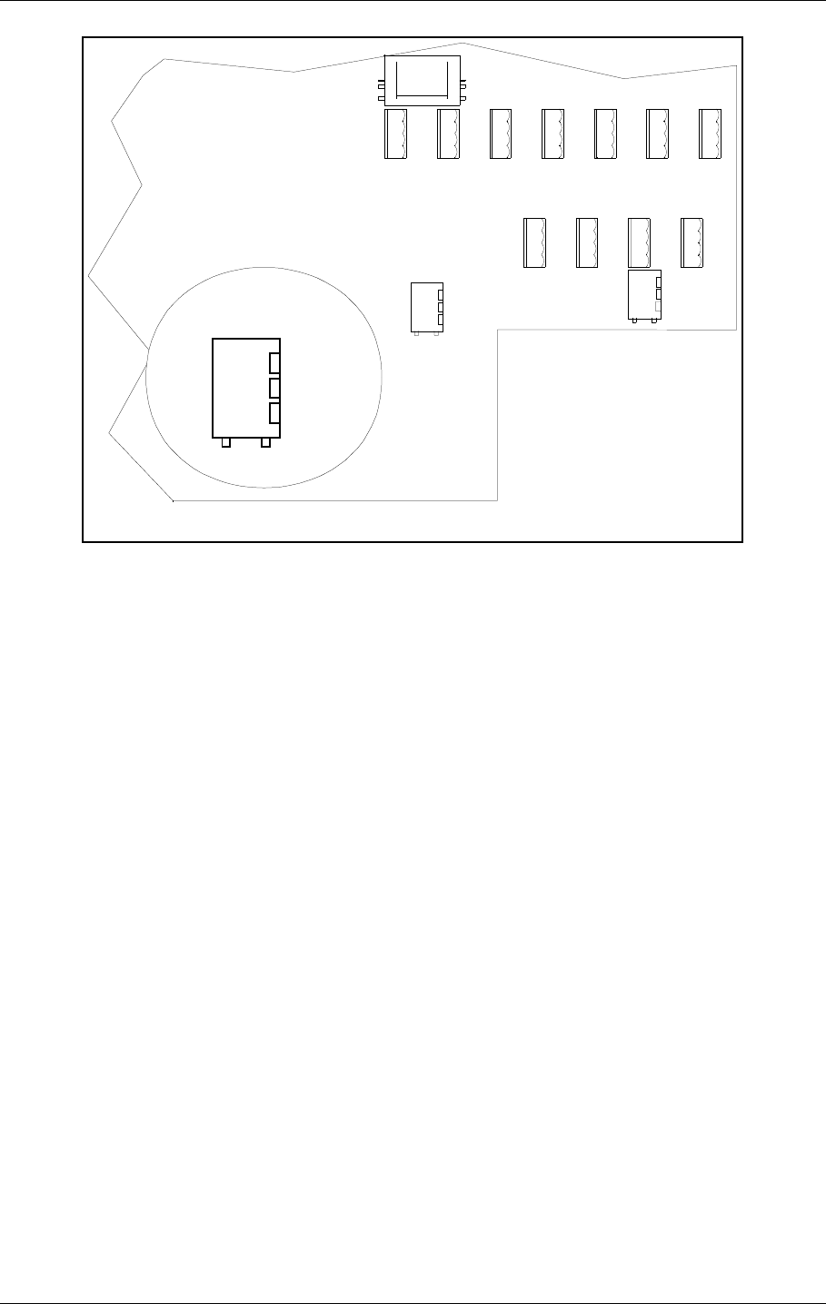
Figure 2-2 shows the open cabinet in front view with indication of plug in board location.
24V DC MAINS
MARKER BEACON SYSTEM
MAIN
OFF
ON
TX TO AIR
LOCAL RS232
POWER
ON
OFF
LOCAL
REMOT E
MANUAL
AUTO
STBY
DISAGR
PARAM
MAINT
BATT
NORMAL
ON/
OFF
CHANGE
OVER
SERVICE
WARNI NG
ALARM
TX1
ESC PREV NEXT
PROTECT
WRIT E
TX1/
TX2
TX2
ENTER
LC1377
HBK780/1
USER MANUAL
2-2
21464-5
NORMARC 7050
MARKER BEACON
Physical organisation ©1999 Navia Aviation AS
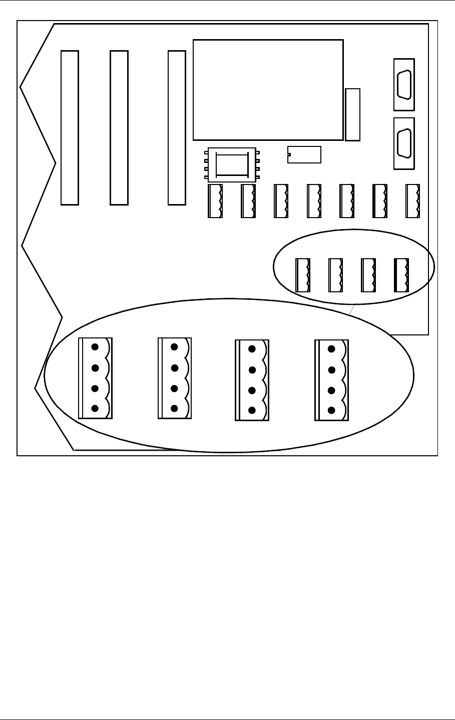
Figure 2-2 NM 7050 Module Location
Notice the location of the different plug in boards. It is essential for the MB to function, that the
cards are placed in these locations. If your MB is configured with only one plugin board of
each type, they must be placed in the number one locations. The backplane is however ,
marked with notifications of where each boards place is..
ΤThe electronic devices inside NM 7050 are sensitive to Electro Static Discharge
(ESD). Please follow the instructions given in the preface of this manual to avoid
damage during servicing and transportation.
PS 1375 TX 1373 MO 1374 PB 1378CI 1376
A
N
T
I
S
T
A
T
Antistatic socket
POWER SUPPLY 1
POWER SUPPLY 2 *)
TRANSMITTER 1
TRANSMITTER 2
MONITOR 1
MONITOR 2 **)
*) Only used in dual power systems (NM 7050 B/D)
**) Only used in dual monitor systems (NM 7050 C/D)
HBK781/1

©1999 Navia Aviation AS 21464-5 System Description
USER MANUALNORMARC 7050
MARKER BEACON
3-1
3 System Description
3.1 Introduction / Overview
The system is housed in a compact cabinet. There are four models/configurations of the NM
7050.
Table3-1 Models / Configurations
As shown in Table 3-1, the beacon can have one or two monitor units and one or two power
supply units. Figure 3-1 shows a block diagram of the MB system.
The monitor and transmitter control function is based on software. The system is based on
modern technology with extensive Remote Monitoring and Maintenance capabilities, and very
high reliability and integrity.
Variant Monitor Power Supply
NM7050A 1 1
NM7050B 1 2
NM7050C 2 1
NM7050D 2 2
USER MANUAL
3-2
21464-5
NORMARC 7050
MARKER BEACON
System Description ©1999 Navia Aviation AS
Figure 3-1 MB block diagram
3.2 Transmitters / Modulators
The NM7050 consists of two TX1373A transmitters. The main transmitter is connected to the
antenna, while the standby transmitter is connected to dummy load. A failure in the main
transmitter will cause an automatic change over to the standby transmitter.
The audio signals are generated in the LF circuitry mainly by a Field Programmable Gate
Array (FPGA). A strap field selects Inner, Middle or Outer Marker settings.
An onboard oscillator generates a 75MHz carrier wave which is amplitude modulated with the
LF
GENERATOR
RF
OSCILLATOR
POWER
AMPLIFIER
CHANGE
OVER
LOCAL
CONTROL
TX1/TX2
ON/
OFF
75 MHz
400 Hz
1.300 Hz
3.000 Hz
KEYBOARD
DISPLAY
AD
CPU
NM7050 - MARKER BEACON
STATION
CONTROL
ADCPU
MONITORING
MAINTENANCE +
RMM INTERFACE
MONITOR RF
FRONTEND MONITOR
BASEBAND+
RF LEVEL
OPTIONAL MONITOR 2
REMOTE
CONTROL
SLAVE
PANEL
LOCAL PC
REMOTE PC
RMM
POWER
SUPPLY
CONNECTION
INTERFACE
TRANSMITTER 1
TRANSMITTER 2
MONITOR RF
FRONTEND MONITOR
AC
DC
DC
DC
LINE+
MODEM
MONITOR 1
OPTIONAL POWER
MO 1374
MO 1374
TX 1373
LC 1377
CI 1376
PS 1375
DUMMY
LOAD
MAINS BATTERY SENSORS ETC.
BASEBAND+
RF LEVEL
MAINTENANCE +
RMM INTERFACE MONITORING
STATION
CONTROL
SPLITTER ONLY PRESENT
IF TWO MONITORS
LF
GENERATOR
RF
OSCILLATOR
POWER
AMPLIFIER
75 MHz
400 Hz
1.300 Hz
3.000 Hz
TX 1373
ON/
OFF
MODULATION DEPTH
OUTPUT RF LEVEL
KEYING NORMAL/OFF/CONT.
STATUS
+20V
+/-15V
+5V
MONITOR 2
DATA
LINE+
MODEM
HBK782/1
RMM

©1999 Navia Aviation AS 21464-5 System Description
USER MANUALNORMARC 7050
MARKER BEACON
3-3
audio signal in the Power Amplifier (PA). The PA is capable of delivering up to 4W power at
97% depth of modulation.
Unwanted frequencies are removed by a lowpass filter after the PA.
3.3 Monitors / Transmitter Control
The marker beacon has one or two MO1374 monitor modules depending on model (Table 3-
1).
The MO1374 is mainly a microprocessor based module. It contains the MB software and
forms the basis of the monitor, station control, system maintenance handling and RMS user
interface.
A detection of error in the transmitter signal causes change-over to the standby transmitter.
Failure of the standby transmitter leads to an alarm and optional shutdown of the standby
transmitter.
On a system with two monitor units, both must report error for alarm to be generated (2 of 2
voting). If the monitors disagree, the WARNING and DISAGR LEDs on the front panel is lit.
The MO1374 consists of two submodules:
The RF frontend receives a RF signal from the antenna (or recombining network for dual
antenna system). It demodulates the signal into analogue values propotional to the RF
power, the modulation depth and the morse code envelope. These parameters are digitized
and monitored by the CPU section.
The CPU section includes an 80CI88 CPU, memory, communication ports and an AD con-
verter system.
3.4 Power Systems
The marker beacon can have either one or two PS1375 power modules depending on model
(Table 3-1). The PS1375 is 100W with 120V or 230V AC input voltage and +28V/3.5 A, +20/
2.5A, ±12V/1.25A and 5V/6A DC output voltages. Outputs are short circuit protected. On the
NM7050 B/D the two modules operate in parallel.
The 28V output is temperature compensated to ensure optimum battery charging. It gives
26.4V at 50°C and linearly increase to 29.6V at -30°C.
The backup battery is an external 24V battery. The battery gives a backup time of 6 hours,
and have external charging possibilities for longer backup time. This battery is automatically
brought into circuit on mains power failure. The charging time is approximately eight hours
with one PS1375 and five hours with two PS1375.
3.5 Remote control system
The remote control unit is used in the tower or in the technical control room. It has indicators
for operating status as well as detailed warnings and an aural alarm device with reset. It can
control equipment on/off and change over, and has an Access Grant switch to allow/inhibit
remote control from the RMM system.
USER MANUAL
3-4
21464-5
NORMARC 7050
MARKER BEACON
System Description ©1999 Navia Aviation AS
The Remote Control Unit is connected to the MB by one pair telephone cable.
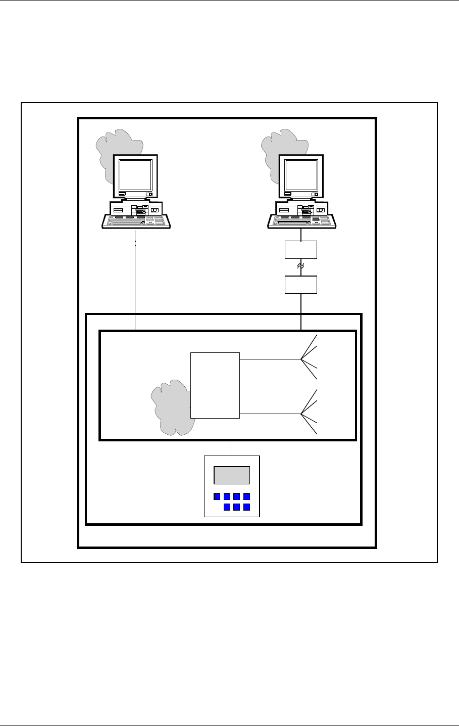
3.6 Remote Maintenance Monitoring (RMM)
The NM7000 series has a built-in Remote Maintenance Monitoring system. This system con-
sists of the RMS system, remote PC terminals with the RMM program installed, and the local
keyboard/display. Figure 3-2 illustrates the RMM/RMS systems.
Figure 3-2 The NM 7050 RMM/RMS systems
The centre of the RMM system is a CPU with the RMS core program. The RMS collects mea-
surements and diagnostic data, and makes them available to the user. The collected informa-
tion allows easy and cost effective maintenance, fault finding and routine reporting. In
addition, system settings are distributed and parameter readings are collected via the RMS/
CPU.
External Personal Computers are used for a user friendly interface to the RMM system. The
equipment has two serial output ports, typically used to connect a local PC and a connection
to a central maintenance facility.
RMS
hardware
RMS
core
program
Local
measuring
points
Maintenance
data bus
RMS
data bus
Local
parameter
storages
Local
Keyboard/
Display
Modem
NM7050
RMS system
RMM system
Local
Remote
RMM
program
Modem
program
RMM
HBK783-1

©1999 Navia Aviation AS 21464-5 System Description
USER MANUALNORMARC 7050
MARKER BEACON
3-5
The local keyboard/display allows readings and controls through an LCD display and a seven-
button keypad. This gives access to the RMM functionality without the need for a PC.
3.7 RMM Access
Access to the RMM system is controlled by multiple hardware and software access controls.
One password is required for each access level, i.e. one password for level 1, two for level 2
and three for level 3. Optional hardware controls may inhibit writing in the upper access lev-
els.
Access level 1
• Readout of all the monitor values, warning and alarm limits.
• Readout of all the maintenance values and warning limits.
• Readout of all the delays.
Access level 2
• TX1 and TX2 : morse normal, continuous or off.
• TX1 and TX2 : test signals 50% depth of mod. and 50% RF level.
• Diagnostics.
Access level 3
• Settings of all the monitor warning and alarm limits.
• Settings of all the maintenance warning limits.
• Settings of all the delays.
3.8 Local Keyboard/Display Functions
Through a menu based interface all main commands, adjustments and monitor limits are
accessible from the front panel keypad and LCD display. In addition a quick read function
gives readout of all main monitor parameters at a glance.
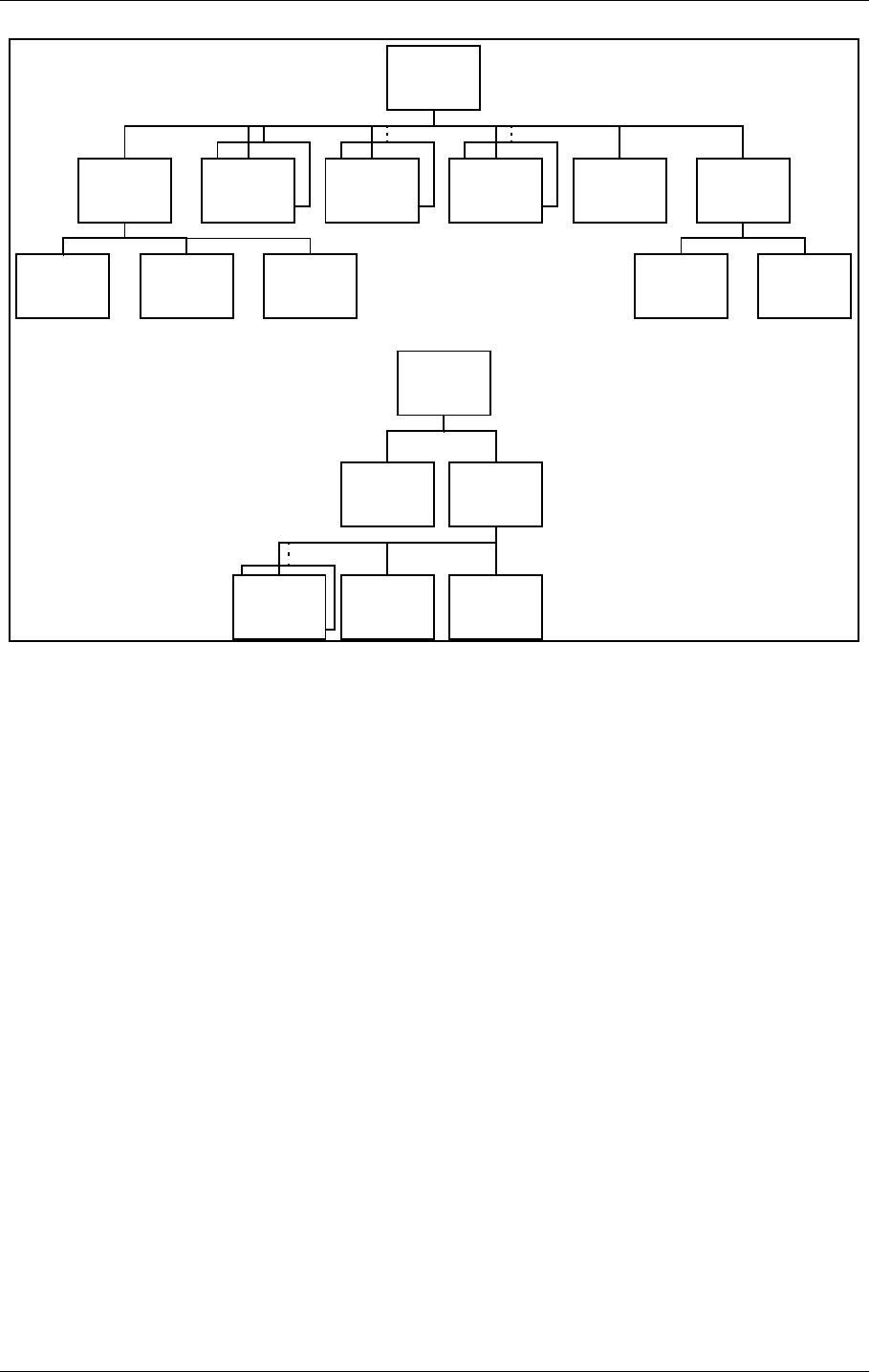
3.9 Document structure
In Figure 3-3 the document structure is shown. The upper tree is the contents of the cabinet,
USER MANUAL
3-6
21464-5
NORMARC 7050
MARKER BEACON
System Description ©1999 Navia Aviation AS
while the lower tree is additional tower equipment.
Figure 3-3 Document structure NM 7050 Marker Beacon system
CAA1370A
Cabinet
Assembly
NM7050A-D
Marker
Beacon
TX1373A
Transmitter
MO1374A
Monitor
PS1375A
Power
Supply
CI1376A
Connection
Interface
PB1378A
Piggy
Back
RC1241A
Remote
Control
RF1242A
Remote
Front
RCA124 0A
Remote
Control
Assembly
LC1377A
Local
Control
SF1344A
Slave
Front
MB1346/7A
Motherboard
CA1348A
Cabinet
PS635B
Power
Supply
RFA1353
Remote
Frame
Assembly
CH1385A/B
Cable
Harness
Additional
Tower
Equipment
HBK859/1

©1999 Navia Aviation AS 21464-5
USER MANUALNORMARC 7050
MARKER BEACON
4-1
Technical Specifications
4 Technical Specifications
NM 7050 Marker Beacon Cabinet.
4.1 Signal Requirements
4.1.1 Transmitter
4.1.2 Modulator
Frequency range 75 MHZ
Frequency tolerance ±0,005 %
Output power range 0,005 – 4 W adjustable.
Fixed attenuator optional in lower range
Harmonic radiation 2,5 UW maximum
spurious radiation 25 UW maximum
OUTPUT POWER STABILITY ±0.5DB
Test function Preset adjustable RF level
MODULATION TYPE AM
Modulation alternatives
KEYED
CONTINUOUS
OFF
MODULATION FREQUENCY AND IDENTIFICATION
INNER MARKER 3000 HZ•Τ•Τ•Τ•Τ•Τ•Τ•
MIDDLE MARKER 1300 HZΤΤ•ΤΤΤΤ•
Outer marker 400 HZΤΤΤΤΤΤ
Modulation depth 95%
adjustable range 45-97 %
MAX. STEP SIZE 0,5 % Depth of Modulation
stability ±4 % Depth of Modulation
Frequency tolerance ±2,5 %
Total harmonic dist. 8 %maximum
Keying
Speed 125 MS/DOT APPROX.
PAUSE TO DOT RATIO 1:1
PAUSE TO DASH RATIO 1:3 dots/SEC
2 dashes/sec
Test function Preset adjustable Depth of Modulation,
normal, continous or no keying

USER MANUAL
4-2
21464-5
NORMARC 7050
MARKER BEACON
Technical Specifications ©1999 Navia Aviation AS
4.1.3 Monitoring
4.1.3.1 Alarm Functions
4.1.3.2 Monitor input levels
4.1.3.3 Monitor stability at nominal levels
4.1.3.4 Warning funktion
4.1.3.5 Protocols
4.1.4 Remote Control
RF power reduction 1,5-3 DB adjustable
Change of modulation depth 50-70 % Depth of Modulation
Keying absence
Alarm identification to automatic
transmitter change over
SENDERUMSCHALTUNG 2-5 sec.
LINE BREAK MB - Remote Control
(DISABLE OPTIONAL) Standby alarm identification
to transmitter shutdown shall be configurable.
Adjustment range, nominal level +1 TO -25 DBM (strap settings for IM, MM
and OM sensitivity)
RF POWER VALUES ±0,5 DB
MODULATION DEPTH VALUES ±1,0 % Depth of Modulation
@ 10 – 30 ºC
±3,0 % Depth of Modulation
@ full temp. range
±2,0 % Depth of Modulation
variation for 3dB RF
reduction @ 10-30°C.
RF POWER REDUCTION 40-75 % of alarm limit
Change of modulation depth 40-75 % of alarm limit
Maintenance parameter outside limits
Mains failure
Monitor 1 to monitor 2 communication SERIAL DATA PROTOCOL (not RS 232)
RMM DATA PROTOCOL RS232
Either

©1999 Navia Aviation AS 21464-5
USER MANUALNORMARC 7050
MARKER BEACON
4-3
Technical Specifications
4.2 Environmental characteristics
4.3 EMV-charakteristics
4.4 Mechanical characteristics
Data Transmission Medium 2-wire line, 600 ohm
Data modulation SERIAL, FSK
Transmitter level -10 DBM ± 2 DB
Receiver dynamic range -10 DBM... -34 DBM OR RS232
or
RS-232 interface in both Marker Beacon and remote control
Operating temperature -40 TO +55 ºC
(main cabinet except
display)
-10 TO +55 ºC
(display, remote con-
trol and slave panel)
Storage temperature -40 TO +60 ºC
HUMIDITY 95% TO +35 °C
DECREASING LINEARLY
TO 60% AT +55 °C
VIBRATION 0.15MM OR 19.6M/S2 (2G)
VERTICAL,10Hz to
500Hz
GENERAL SPECIFICATIONS FOR EMC ETS 300 339
EN50081-1 (emmission)
EN50082-2 (immunity)
EN61000-3-2 (harmonic current emmission)
EN61000-3-3 (voltage fluctuations and flicker)
SPURIOUS AND HARMONICS CISPR 22
SAFETY EN 60950
Dimensions (hxwxd):
MB CABINET 267 X 450 X 343 MM
REMOTE CONTROL 71 X 132 X 200 MM
SLAVE PANELS 51 X 132 X 200 MM
The MB rack is wall mounted. The remote control and slave panel fit a 19" shelf.

USER MANUAL
4-4
21464-5
NORMARC 7050
MARKER BEACON
Technical Specifications ©1999 Navia Aviation AS
4.5 Power supply
OPERATING VOLTAGE:
MAIN SUPPLY 230 V +15 %/-20 %, 45-65 HZ,
OR 120 V +15 %/-20 %, 45-65 HZ
STAND-BY BATTERY 24 V DC NOMINAL,
float charged by the main Supply.
The battery is able to use an external
charger.
The equipment is able to operate
without battery.
POWER CONSUMPTION:
MB CABINET: < 50 W
REMOTE CONTROL < 5 W
BATTERY CHARGER ADAPTED TO 5 HOURS (NM 7050 B/D) or 8
hours (NM 7050 A/C) charging time to 90%
battery capacity for a battery giving 6 hours
operation.
External battery charges may be connected
for longer operation, and shorter charging
time.
©1999 Navia Aviation AS 21464-5 Electrical installation
USER MANUALNORMARC 7050
MARKER BEACON
5-1
5 Electrical installation
5.1 Marker beacon cabinet
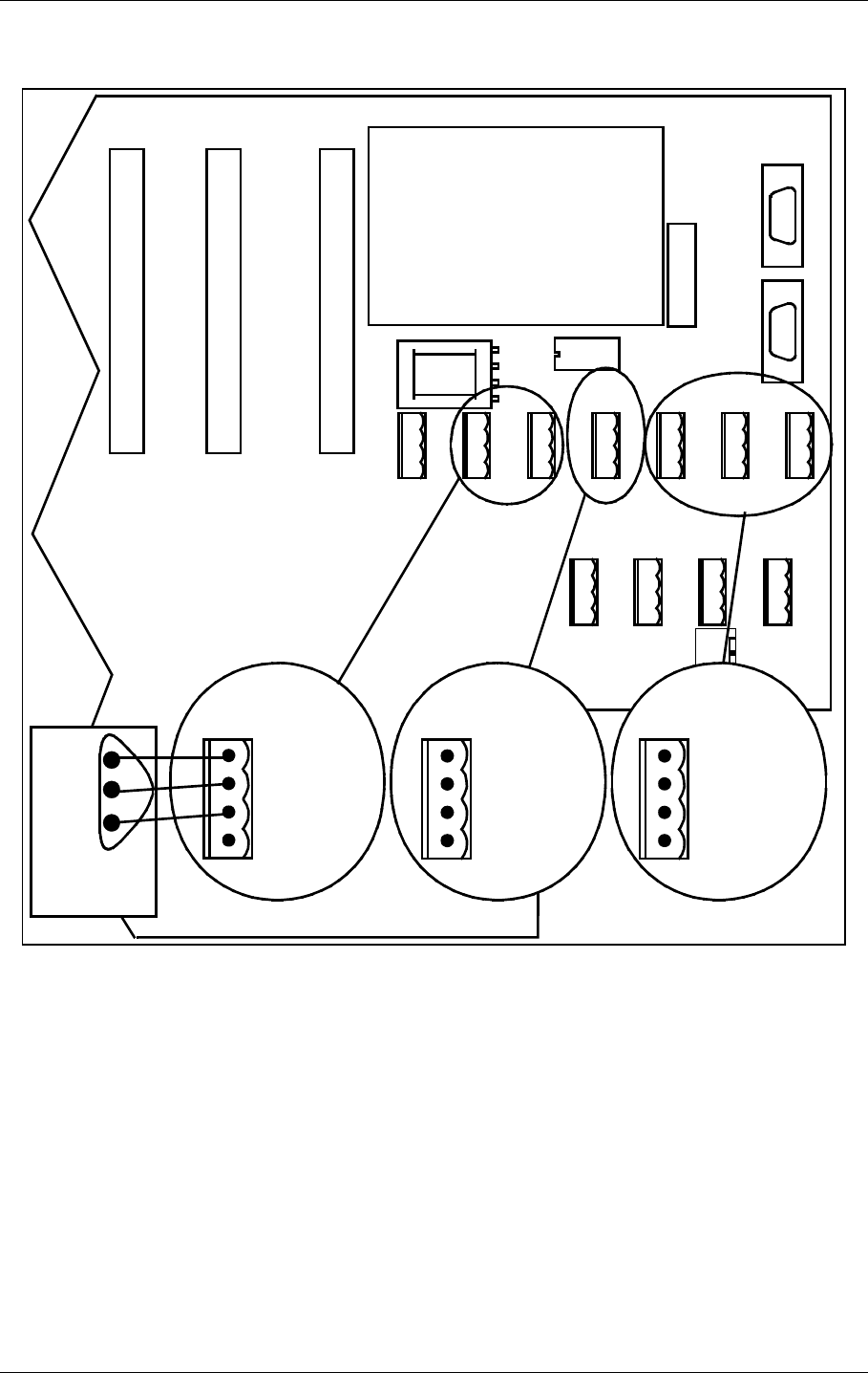
5.1.1 Connection Overview
All electrical connections except the local PC connection, the mains connection and the RF IN
and OUT connections are on the CI1376 connection interface board inside the cabinet.
Figure 5-1 Marker Beacon main cabinet connection overview
5.1.2 RF In and Out
• The output signal RF OUT is connected to the antenna with N-connectors and 50 Ω coaxial
cable.
The input signal RF IN is connected to the antenna probe with N-connectors and 50 Ω coaxial
cable.
GND
L
N
RF INRF OUT
ON ON
OFF
24V DC OFF
POWER
MAINS
ON/
OFF
LOCAL RS232
DISAGR
STBY
MAINT
BATT
PARAM
REMOTE AUTO
LOCAL MANUAL
CHANGE
OVER
PROTECT
WRITE
TX1/
TX2
MAIN
TX TO AIR
NORMAL
WARNING
ALARM
SERVICE
TX1 TX2
MARKER BEACON SYSTEM
ESC PREV NEXT ENTER
CABINET UNDERSIDE
FRONT VIEW WITH FRONT PLATE
FRONT VIEW WITHOUT FRONT PLATE RF IN AND OUT
MAINS POWER
LOCAL PC (RS 232)
REMOTE CONTROL (RS 232)
REMOTE PC (RS 232)
3 ANALOGUE CHANNELS
AC LEVEL
4 DIGITAL PORTS
TEMP. INDOOR AND OUTDOOR
BATTERY
A
N
T
I
S
T
A
T
HBK784/1
USER MANUAL
5-2
21464-5
NORMARC 7050
MARKER BEACON
Electrical installation ©1999 Navia Aviation AS
.
Figure 5-2 RF cable connection
5.1.3 Battery
The external backup battery is connected between BATT GND (-) and BATT +24V (+) on the
connector marked BATTERY on CI 1376.
A 16Ah battery gives approximately six hours backup time with 5-8 hours charging time
dependent on model. For longer backup time an external charger is required to be able to
charge the battery within a reasonable time. An external battery protection circuit (like Nor-
marcs BP 543) has to be connected between the EXT. CHARGER (+) and BATT GND (-) input.
In addition MAINS directly on NM 7050 has to be disconnected. Figure 5-4 shows the connec-
tions schematically.
RF OUT RF IN
HBK785/1
©1999 Navia Aviation AS 21464-5 Electrical installation
USER MANUALNORMARC 7050
MARKER BEACON
5-3
Figure 5-3 Battery connection
Figure 5-4 External charger connection
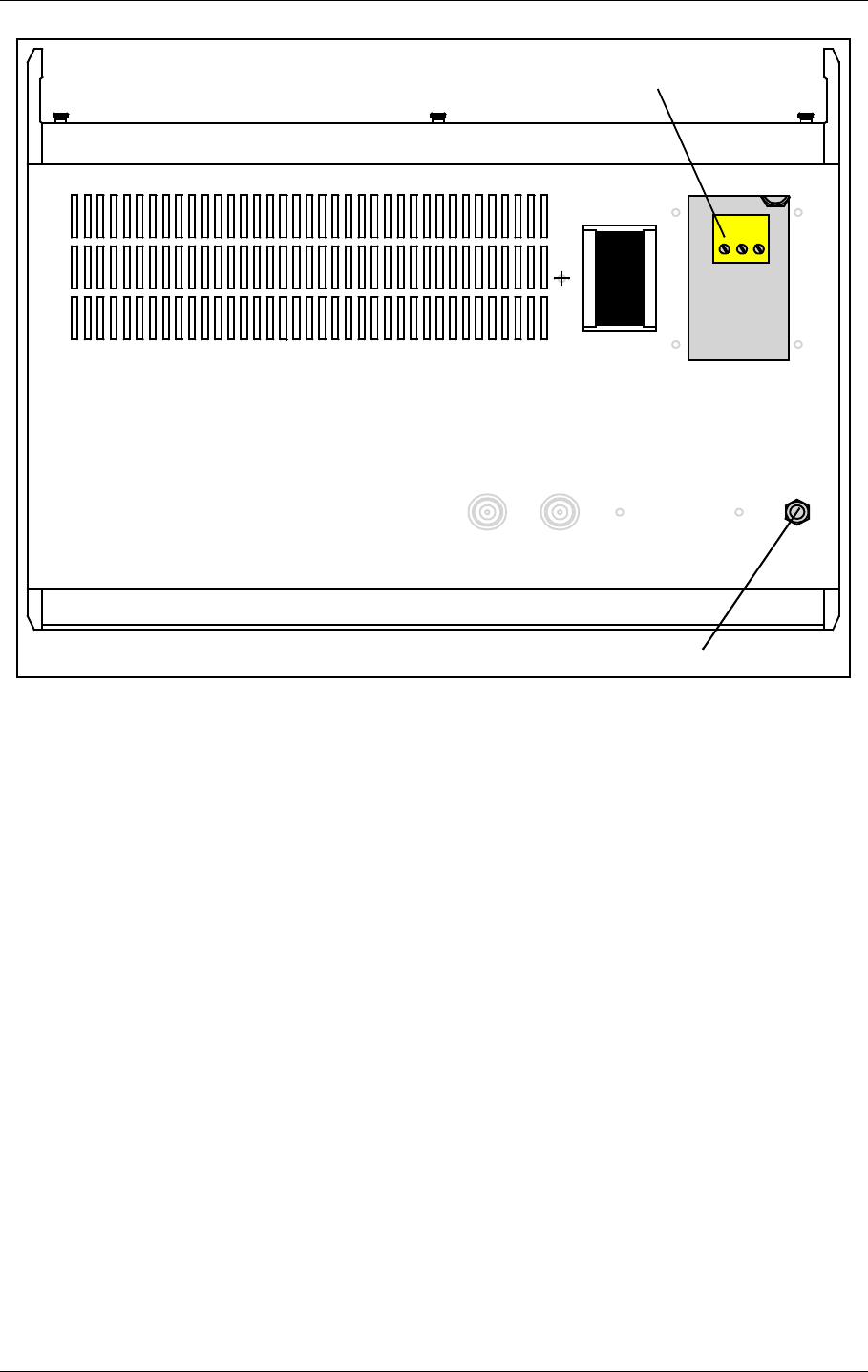
5.1.4 Mains
The mains power cable connections are underneath the cabinet. They are covered by a alu-
minium plate fastened with four screws. The cable itself is threaded through the cable gland
and the three wires are connected to the terminals N, L and GND shown below in figure 6-4.
CI 1376
REMOTE
CONTROL
LINE
TEMP
OUTDOOR
TEMP
INDOOR
AC LEVEL ANA CHA1 ANA CHA2 ANA CHA3
DIG PORT A DIG PORT B DIG PORT C DIG PORT D
BATT GND
EXT CHARGE
BATT +24V
1
2
3
BATTERY
BATT GND
EXT CHARGE
BATT +24V
BATTERY
HBK786/1
AC
DC
BP 543
BATTERY
EXT.CHARGE
BATT +24V
BATT GND
MAINS
EXTERNAL
CHARGER
BATTERY
PROTECTION
NM 7050
HBK863/1
USER MANUAL
5-4
21464-5
NORMARC 7050
MARKER BEACON
Electrical installation ©1999 Navia Aviation AS
Figure 5-5 Power connection
5.1.5 Modem Power
A DC powered modem or other external equipment designed for 22V-27V DC can be con-
nected to the terminal block marked MODEM POWER. Maximum current consumption
should be 800 mA.
MAINS POWER
GND
L
N
GROUND CABLE CONNECTION
HBK787/1
©1999 Navia Aviation AS 21464-5 Electrical installation
USER MANUALNORMARC 7050
MARKER BEACON
5-5
Figure 5-6 Modem Power
5.1.6 Remote Control
The remote line and remote control is connected to the CI 1376 connection interface board as
illustrated in Figure 5-7.
• FSK_[A,B] is the modem line pair.
• GND is main cabinet ground
A suitable female connector for the remote line is Weidemüller BLZ-5.08/4 or equivalent.
Alternatively the remote control connection is done with a RS 232 interface. The mode is con-
figured on MO 1374, refer to 7.2.3.
Note: The position of RXD and TXD is interchanged from the normal RS-232 layout in the
Remote Control connector. Therefore a special cable must be used for connection to external
equipment.
CI 1376
REMOTE
CONTROL
LINE
TEMP
OUTDOOR
TEMP
INDOOR
AC LEVEL ANA CHA1 ANA CHA2 ANA CHA3
DIG PORT A DIG PORT B DIG PORT C DIG PORT D
-(GND)
1
2
3
BATT GND
EXT CHARGE
BATT +24V
BATTERY
-
+
+ (+24V DC)
MODEM POWER
MODEM POWER
H1116/1
USER MANUAL
5-6
21464-5
NORMARC 7050
MARKER BEACON
Electrical installation ©1999 Navia Aviation AS
Figure 5-7 Remote control connection
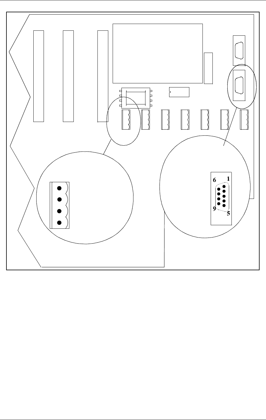
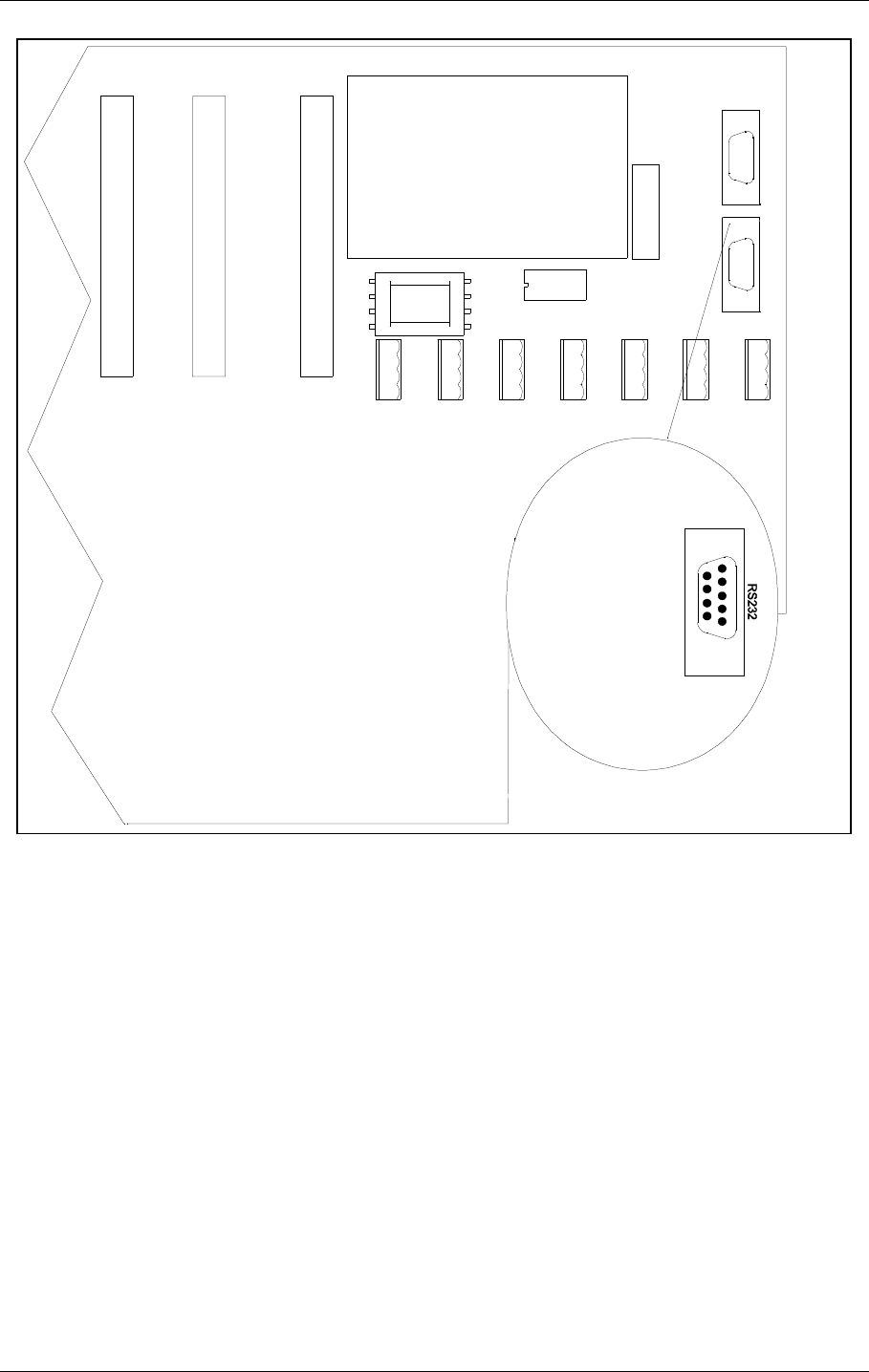
5.1.7 PC and Modem
Modem connections for remote PC are the standard pin out RS232, 9 pins DSUB connector
on the CI1376 connection interface board marked remote-rmm as illustrated in Figure 5-8.
For local PC connection use the RS232 on front panel Figure 5-9.
CI 1376
PB 1378
REMOTE
CONTROL
LINE
TEMP
OUTDOOR
TEMP
INDOOR
AC LEVEL ANA CHA1 ANA CHA2 ANA CHA3
REMOTE RMM
RS232
REMOTE CONTOL
RS232
CONFIGURATION
1 - GND
2 - RC_LINE B
4 - Not used
1 - Not used
3 - RXD
2 - TXD
4 - Not used
5 - GND
6 - Not used
7 - Not used
8 - Not used
9 - Not used
REMOTE
CONTROL
REMOTE
CONTROL
LINE
RS-232
HBK788/3
2 - RC_LINE A
©1999 Navia Aviation AS 21464-5 Electrical installation
USER MANUALNORMARC 7050
MARKER BEACON
5-7
.
Figure 5-8 Modem and modem battery backup connection
CI 1376
PB1378
REMOTE
CONTROL
LINE
TEMP
OUTDOOR
TEMP
INDOOR
AC LEVEL ANA CHA1 ANA CHA2 ANA CHA3
REMOTE RMM
RS232
REMOTE CONTOL
RS232
CONFIGURATION
DIG PORT A DIG PORT B DIG PORT C DIG PORT D
1-CD
2-RXD
3-TXD
4-DTR
5-GND
6-Not used
7-RTS
9-CTS
9-Not used
REMOTE RMM
61
95
HBK789/1
USER MANUAL
5-8
21464-5
NORMARC 7050
MARKER BEACON
Electrical installation ©1999 Navia Aviation AS
Figure 5-9 Local PC RS232 connection
5.1.8 Analogue Inputs
The analogue inputs are connected to the CI1376 connection interface board as illustrated in
Figure 5-10.
The inputs are:
• Analogue Channel 1-3 - three differential DC analogue inputs, P (pin-1) is the positive and
N (pin-3) is the negative terminal, and pin 2 is GND.
Maximum voltage: ±15V
Input impedance: 10kΩ
• Temp Indoor and Outdoor - temperature measurement inputs with interface to an LM35
temperature sensor.
Maximum voltage: ±15V
Input impedance: 10kΩ
• AC Level - AC level measurement input. Intended for use with a battery eliminator to moni-
tor the mains voltage.
Maximum voltage: 24Vpp
1 - Not used
2 - RXD
3 - TXD
4 - Not used
5 - GND
6 - Not used
7 - RTS
8 - CTS
9 - Not used
HBK790-1
©1999 Navia Aviation AS 21464-5 Electrical installation
USER MANUALNORMARC 7050
MARKER BEACON
5-9
Input impedance: 10 kΩ
Figure 5-10 Analogue input connections
5.1.9 Digital Inputs and Outputs
Eight bi-directional digital channels (numbered 0-7) are sited on the CI1376 connection inter-
face board as illustrated in Figure 5-11.
Logical levels: TTL
Input impedance: 560Ω.
A suitable female connector is Weidemüller BLZ-5.08/4 or equivalent.
CI 1376
PB 1378
REMOTE
CONTROL
LINE
TEMP
OUTDOOR
TEMP
INDOOR
AC LEVEL ANA CHA1 ANA CHA2 ANA CHA3
REMOTE RMM
RS232
REMOTE CONTOL
RS232
CONFIGURATION
DIG PORT A DIG PORT B DIG PORT C DIG PORT D
1-ANLG*P
2-GND
3-ANLG*N
4-Not used
ANALOGUE
CHANNEL 1-3
1-VACP
2-GND
3-VACN
4-Not used
AC LEVEL
1-VDD
2-T*DOOR
3-GND
4-Not used
TEMP *
V+
Vtemp
GND
LM 35
Bottom view
HBK791/1
USER MANUAL
5-10
21464-5
NORMARC 7050
MARKER BEACON
Electrical installation ©1999 Navia Aviation AS
Figure 5-11 Digital input/output connections
5.1.10 Power for Modem or other external devices
A DC powered modem or other external equipment designed for 22V - 27V DC can be con-
nected to the screw terminal J30. Maximum current consumption should be 0.8A.
The terminal marked OUT+ is 22V - 27V DC, OUT- is ground
5.1.11 Remote Control Interface (MB rack)
The transmission medium (telephone line (FSK modem) or RS 232) to the Remote Control
can be selected by plugs and link straps S700 and S701 on the MO1374 module:
1- DIGIN 1
2- GND
3- DIGIN 0
4-GND
1- DIGIN 3
2- GND
3- DIGIN 2
4-GND
1- DIGIN 5
2- GND
3- DIGIN 4
4-GND
1- DIGOUT 0
2- GND
3- DIGOUT 1
4-GND
DIGITAL PORTS
A
B
CD
CI 1376
PB 1378
REMOTE
CONTROL
LINE
TEMP
OUTDOOR
TEMP
INDOOR
AC LEVEL ANA CHA1 ANA CHA2 ANA CHA3
REMOTE RMM
RS232
REMOTE CONTOL
RS232
CONFIGURATION
DIG PORT A DIG PORT B DIG PORT C DIG PORT D
HBK792/1
©1999 Navia Aviation AS 21464-5 Electrical installation
USER MANUALNORMARC 7050
MARKER BEACON
5-11
5.2 Tower equipment
5.2.1 Remote Control Connection
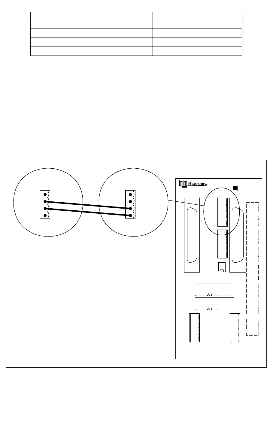
The remote control is connected to the corresponding MB by connecting the REMOTE CON-
TROL connector on CI1376 to P9 on MB1346, as shown in Figure 5-12.
Suitable female connectors are Weidemüller BLZ-5.08/4 or equivalent. 600 Ω cable should
be used.
Figure 5-12 Remote control to MB connection
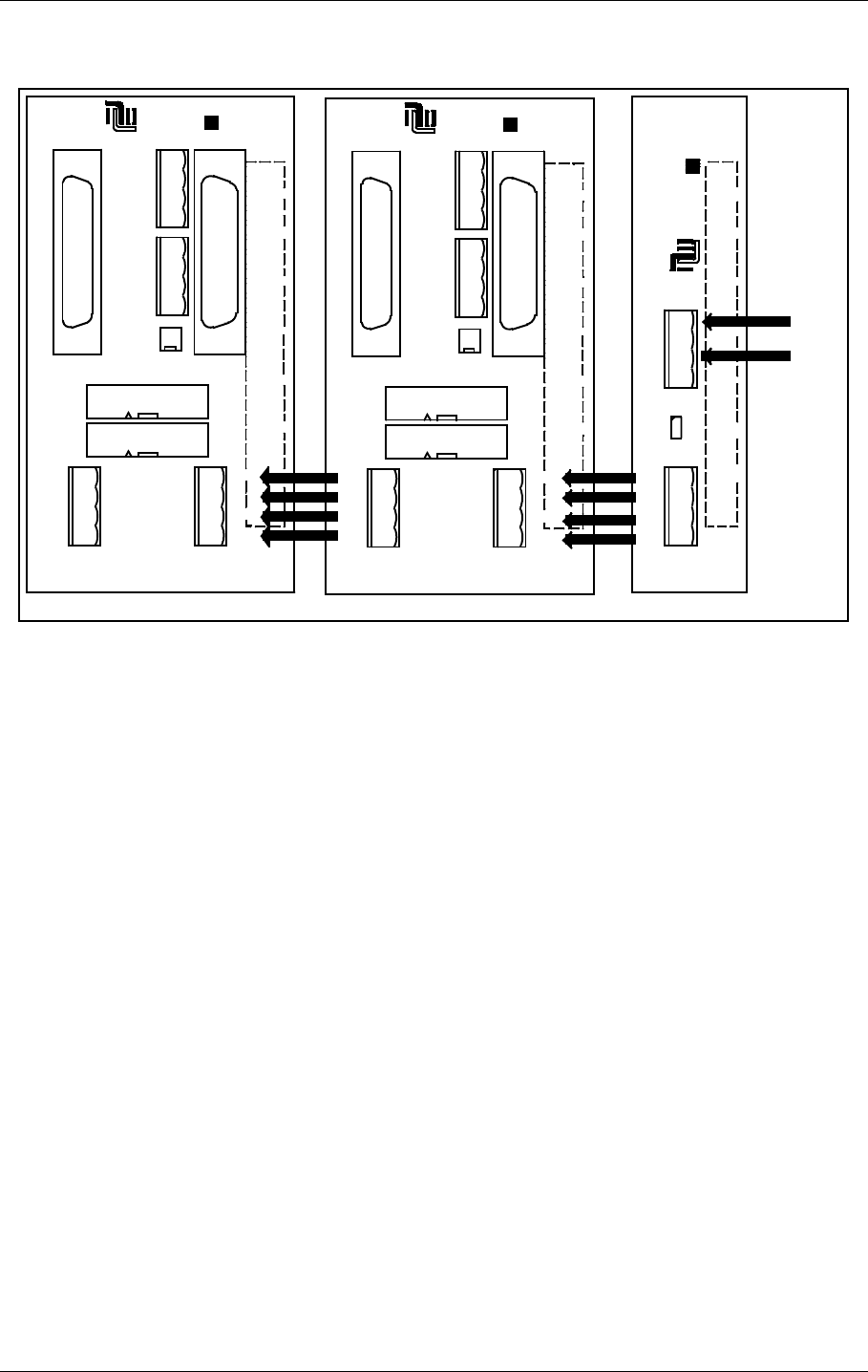
The power supply to the remote control is connected according to Figure 5-13. The battery
charger is connected to P2 on the MB1347 - power supply motherboard. Output connector P3
on MB1347 is connected to input connector P4 on MB1346 - remote control motherboard.
Several MB1346's are serial linked by connecting P5 on one board to P4 on the next.
S700 pins
connected S701 pins
connected Function Connector on CI 1376:
1-2 1-2 Telephone line P3 Remote Control Line
3-4 3-4 RS 232 P4 Remote Control RS232
5-6 5-6 Not used Not used
REMOTE
CONTROL
1 - GND
2 - FSK_P
3 - FSK_N
4 - GND
J2 P3
P6
P7
P4
P5
P9
P10
P8
OPTO OUT
2-ALARM (E)
1-ALARM (C)
4-NORM (E)
5-WARN (C)
6-WARN (E)
7-STBAL (C)
8-STBAL (E)
3-NORM (C)
GND
5V
24V
V_DIM
GND
5V
24V
V_DIM
POWER OUT POWER IN
AUX IN/OUT
SLAVE
DIRECT
INTERLOCK
TXOFF
ALARM
LINE A
LINE B
RX A
RX B
TX A
TX B
SLAVE RS485
J1
ABC
1
5
30
20
25
15
10
ALT.LINK
MB1346
P9
1 - TXOFF
2 - ALARM
3 - LINE_A
4 - LINE_B
CI1376
on
corresponding
MB
HBK793-1
USER MANUAL
5-12
21464-5
NORMARC 7050
MARKER BEACON
Electrical installation ©1999 Navia Aviation AS
Suitable female connectors are Weidemüller BLZ-5.08/4 or equivalent.
Figure 5-13 Remote control power supply connections
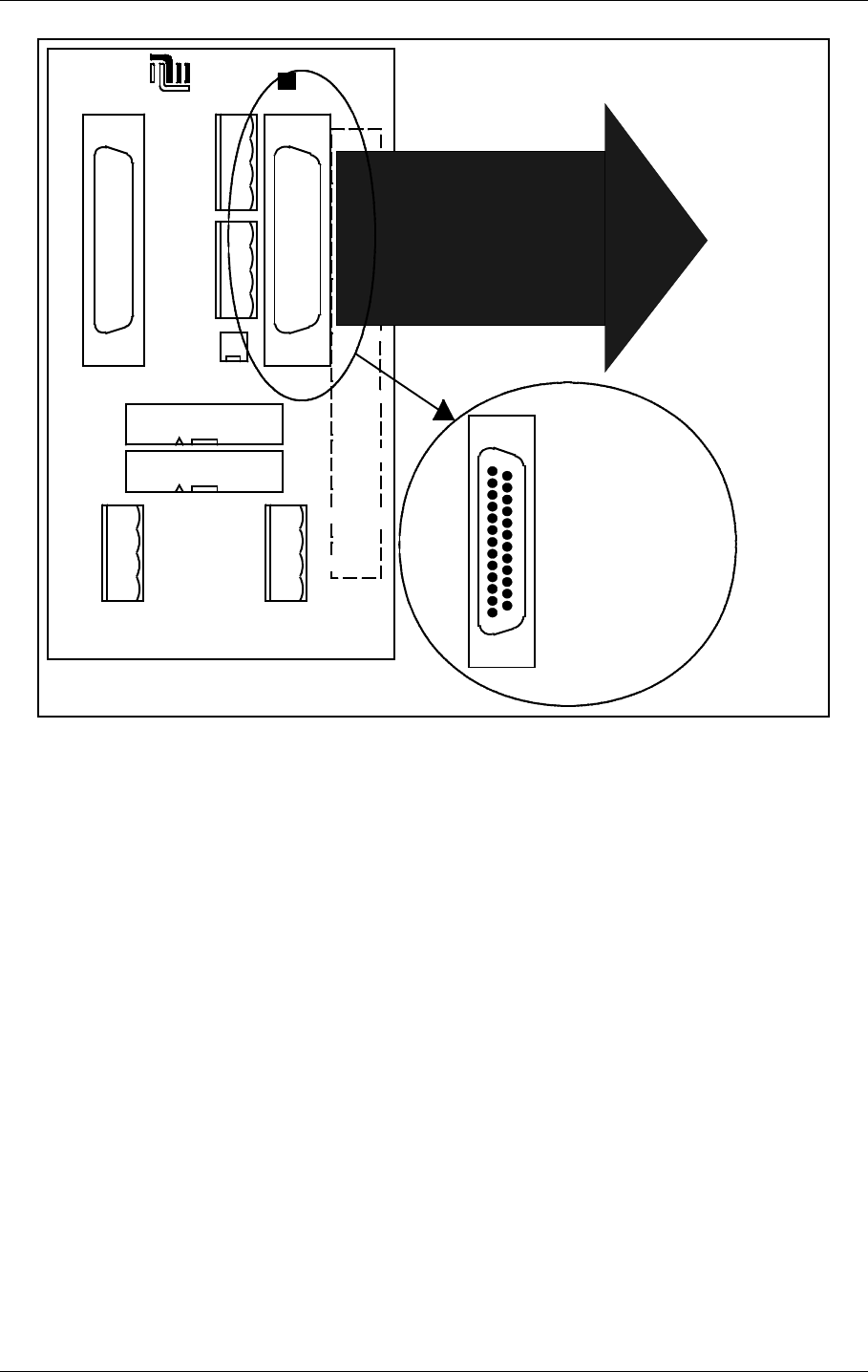
5.2.2 Remote Slave Connection
The remote slave panel SF1344 is connected to the corresponding remote control's mother-
board by connecting P3 on MB1346 to P1 on SF1344. P10 on MB1346 is not used. See Fig-
ure 5-14.
Suitable connectors are standard 25 pins female DSUB (Harting 0967 025 0442 and 0967
225 4704 or equivalent), connected by a 10 wire 1:1 cable.
J2 P3
P6
P7
P4
P5
P9
P10
P8
NORMARC
OPTO OUT
2-ALARM (E)
1-ALARM (C)
4-NORM (E)
5-WARN (C)
6-WARN (E)
7-STBAL (C)
8-STBAL (E)
3-NORM (C)
GND
5V
24V
V_DIM
GND
5V
24V
V_DIM
POWER OUT POWER IN
AUX IN/OUT
SLAVE
DIRECT
INTERLOCK
TXOFF
ALARM
LINE A
LINE B
RX A
RX B
TX A
TX B
SLAVE RS485
J1
ABC
1
5
30
20
25
15
10
ALT.LINK
MB1346
P2
P3
S1
GND
24V
POWER IN
GND
5V
24V
V_DIM
POWER OUT
V_DIM=24V
MB1347
NORMARC
30
25
20
15
10
5
1
AB
J1
J2 P3
P6
P7
P4
P5
P9
P10
P8
NORMARC
OPTO OUT
2-ALARM (E)
1-ALARM (C)
4-NORM (E)
5-WARN (C)
6-WARN (E)
7-STBAL (C)
8-STBAL (E)
3-NORM (C)
GND
5V
24V
V_DIM
GND
5V
24V
V_DIM
POWER OUT POWER IN
AUX IN/OUT
SLAVE
DIRECT
INTERLOCK
TXOFF
ALARM
LINE A
LINE B
RX A
RX B
TX A
TX B
SLAVE RS485
J1
ABC
1
5
30
20
25
15
10
ALT.LINK
MB1346
From
24VDC
power
supply
HBK794/1
©1999 Navia Aviation AS 21464-5 Electrical installation
USER MANUALNORMARC 7050
MARKER BEACON
5-13
Figure 5-14 Remote slave connection
J2 P3
P6
P7
P4
P5
P9
P10
P8
NORMARC
OPTO OUT
2-ALARM (E)
1-ALARM (C)
4-NORM (E)
5-WARN (C)
6-WARN (E)
7-STBAL (C)
8-STBAL (E)
3-NORM (C)
GND
5V
24V
V_DIM
GND
5V
24V
V_DIM
POWER OUT POWER IN
AUX IN/OUT
SLAVE
DIRECT
INTERLOCK
TXOFF
ALARM
LINE A
LINE B
RX A
RX B
TX A
TX B
SLAVE RS485
J1
ABC
1
5
30
20
25
15
10
ALT.LINK
MB1346
1:1
To P1
on
SF1344
1
13
14
25
1 - GND
2 - ALARM
3 - WARNING
4 - NORMAL
7 - GND
15 - V24P
19 - ON_OFF
21 - SILENCE
23 - INTERLOCK (if used)
25 - BUZZER
HBK795/1

©1999 Navia Aviation AS 21464-5 Antenna
USER MANUALNORMARC 7050
MARKER BEACON
6-15
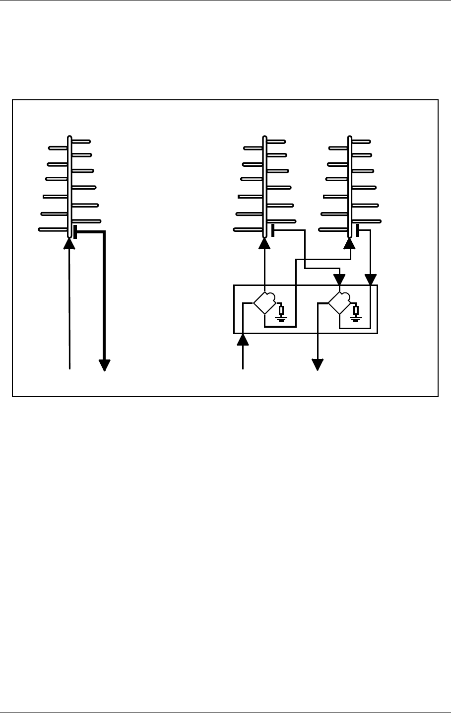
6 Antenna
Normarc supplies single and dual antennas, NM 3561 and NM 3562 respectively. The single
antenna may be used for inner, middle and outer marker, while the dual antenna is specially
designed for outer markers. The advantage of the dual antenna is a lower spread in FLYING
THROUGH TIME inside the localizer coverage area. In addition to two antenna elements, the
monitor and distribution network DI 726 is included in NM 3562.
Figure 6-1 Antenna block diagram
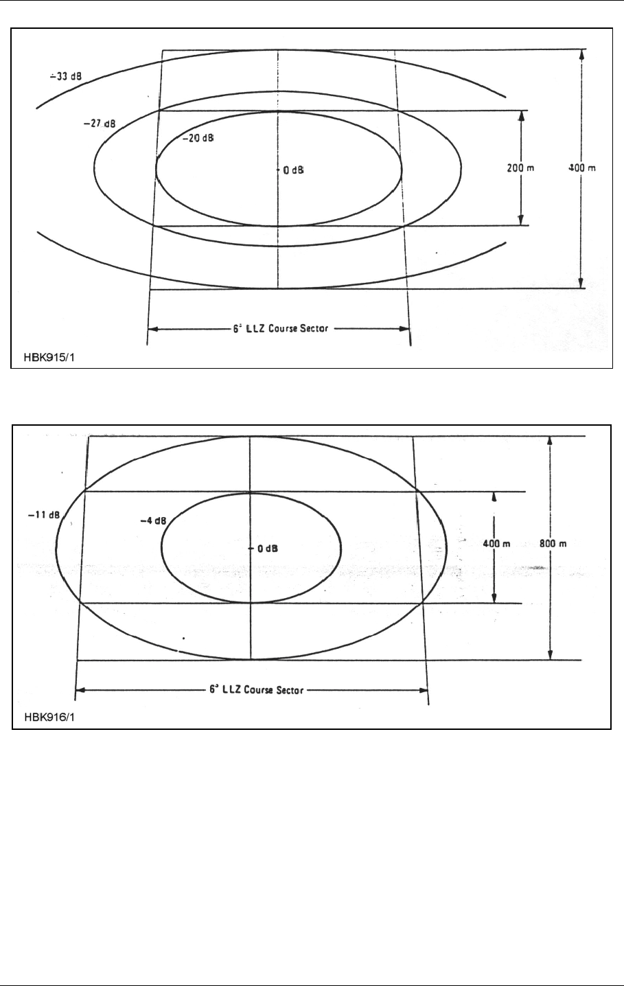
Figure6-2 shows the field strength of the radiated signal directly above the middle marker
antenna. Figure6-3 and Figure6-4 illustrate the field strength above the outer marker
antenna, using single and dual antenna, respectively. The localizer course sector is scetched.
Along an elliptical curve, the field strength is constant. If you look at the diagrams as ordinary
geographical maps, you will see that the dual antenna "field-strength-mountain" is steaper
and more stretched sideways than the single antenna "mountain". This corresponds to a
sharper on/off response on the aircraft's marker beacon instruments.
SINGLE ANTENNA SYSTEM
NETWORK
DI 726
RF OUT RF IN
DUAL ANTENNA SYSTEM
RF OUT RF IN
5050
HBK914-1
©1999 Navia Aviation AS 21464-5 Antenna
USER MANUALNORMARC 7050
MARKER BEACON
6-17
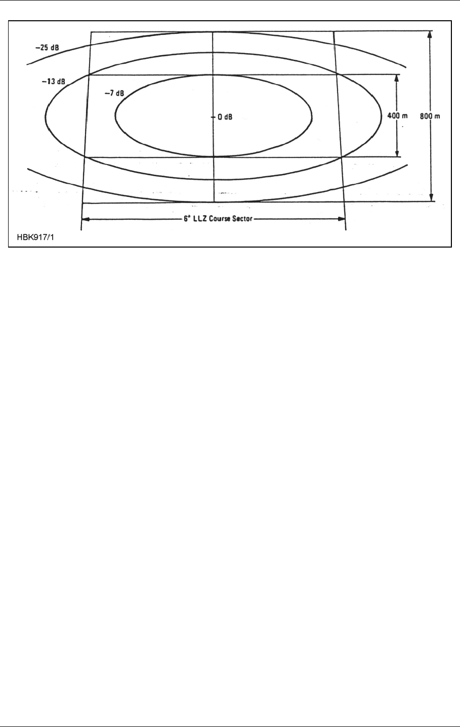
Figure 6-4 Equi-signal-contours for Outer Marker Beacon, Dual Antenna
6.1 Antenna NM 3561 / NM 3562 For Ils Marker Beacon
The NM 3561/NM 3562 Marker Beacon Antennas are log-periodic dipoles possessing proper-
ties of high gain and directivity, and low side lobes. The performances og the antennas con-
form to ICAO Annex 10 item 3.1.6, and are such that they are largely independent of
environment factors such as rain, snow and ice, and they can therefore be located at «diffi-
cult» sites. The directivity of the antennas can, if required, be even further increased by add-
ing additional elements to the array.
The radiation patterns for the antennas are almost unaffected by the surrondings, and the
antennas are therefore suitable for offset location where tilting of the antennas is necessary in
order to obtain the required signal coverage. (Refer to figure A-1)
Figure12-3, 12-4 and 12-5 shows constant field strenght lines through points in the glide path
(GP angle 3º). The marker beacons are located vertically beneath the localizer course line at
distance of 1050 m (middle marker) and 3.9 nautical miles (outer marker) from the threshold.
The field strengths specified are relative to the maximum level directly above the antenna.
The figures show that for an aircraft travelling at a speed of 50 m/s (96 knots) within the maxi-
mum allowable course sector of 6º the duration of the visual indication will be within the pre-
scribes limits. The instrument panel lamp should be adjusted so as to switch on or off at the
levels indicated in the figures i.e. -27 dB to -33 dB for Figure12-3, -11 dB to Figure12-4, and -
13 dB to -25 dB for Figure12-5.
The marker beacon antennas are mounted on poles, with the dipoles parallel to the course
line. The rear end of an antenna should be at least 2 metres above the ground.
The NM 3562 antenna comprises two elements, and is fed via a distribution network (DIA 726)
which splits the transmitter power into two equal parts. The network is a coaxial cable hybrid
housed in silumine box together with the monitor network which is used to combine the signal
from the two monitor probes.

USER MANUAL
6-18
21464-5
NORMARC 7050
MARKER BEACON
Antenna ©1999 Navia Aviation AS
Specifications: NM 3561: NM 3562:
Antenna construction 1 LPDA 2 LPDAs
Frequency 75 MHz 75 MHz
Gain 8,2 dB 11 dB
VSWR 50 Ohm 1,2 dB 1,2 dB
Required RF power 0,5W 0,4W
Dimensions 3,3 x 2,2 m 3,3 x 4,7 m
Weight 50 kg 110 kg
Mounting Both types: 2.2 metres above ground
Temperature Both types: -40ºC to +70ºC
Wind velocity Both types: up to 180 km/h