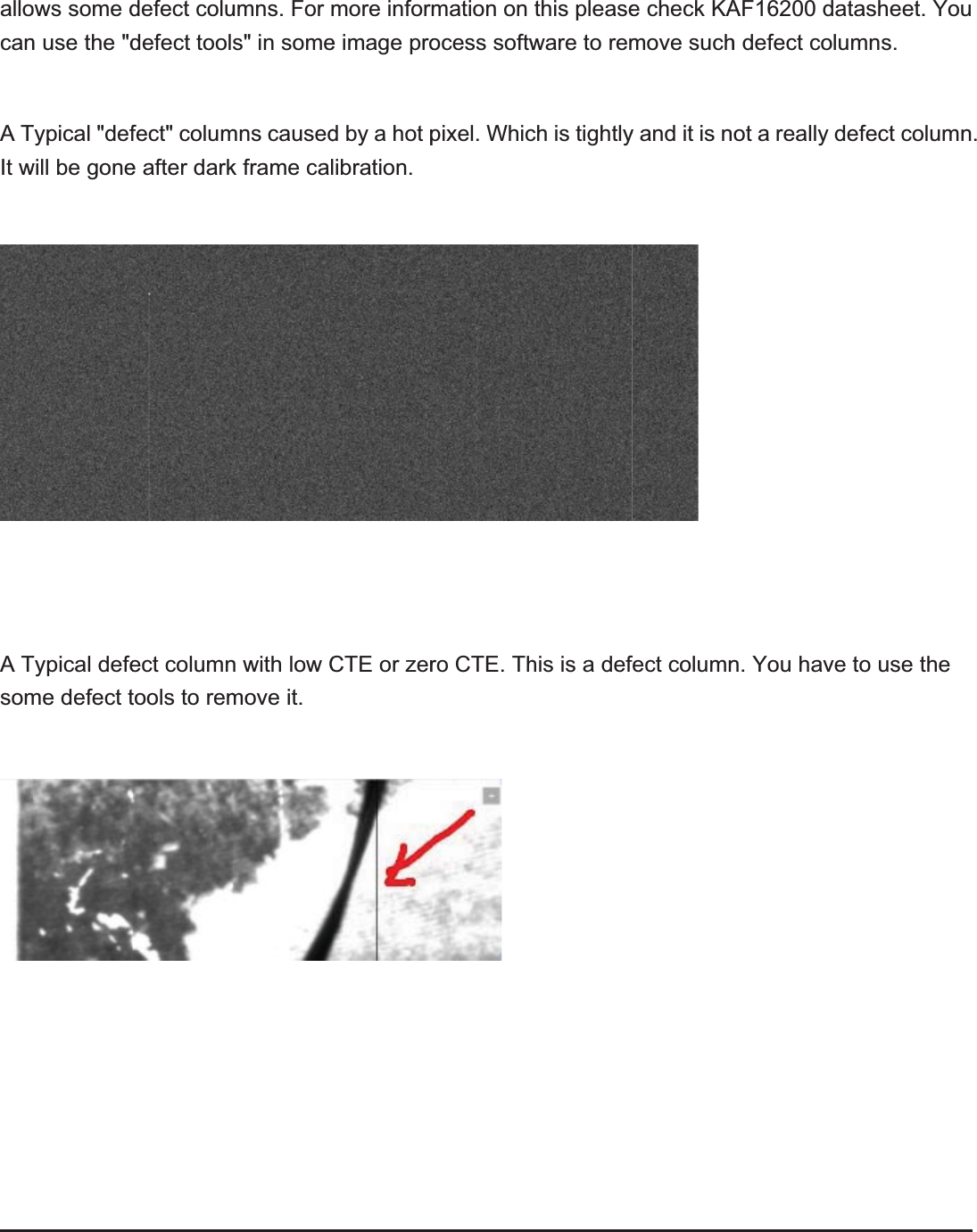
Light Speed Vision 16200A Camera User Manual
Light Speed Vision (Beijing) Co.,Ltd. Camera
UserManual.wiki
>
Light Speed Vision
>
16200A User Manual
User manual
Navigation menu
Upload a User Manual
Namespaces
Wiki Guide
HTML
PDF
Info
Views
User Manual
Discussion / Help
Navigation
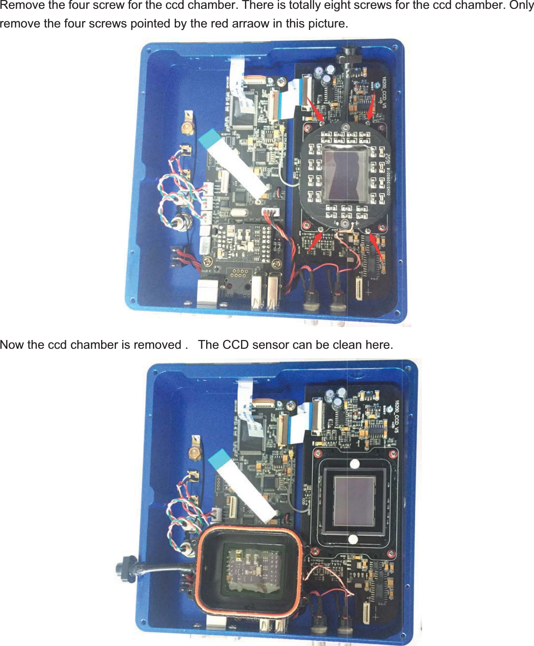
![)ROI9KZ[Q'J\GTIK[VZNKLORZKKJ([ZZUTX]NKKRVGXGTJYKRKIZXGSKZKXY7.?))*,,ORZKX=NKKRGTJIROIQ6XUVKXZOKYZUYKZ[V](https://usermanual.wiki/Light-Speed-Vision/16200A/User-Guide-3112104-Page-8.png)
![)ROITyseThiStreQ)UTTKIZypicalQnsors is a typietch to bacZZUIUTTKQHY162ical Dark Fckground leIZHUZNIGS00A DaFrame at 3evelSKXGGTJLOark/Flat/300sec exRZKX]NKKR/Calibraposure, -1ated Ima15C, gain=agesw=0. Part ofwith Graf the imagde2e. 1:1 zooom](https://usermanual.wiki/Light-Speed-Vision/16200A/User-Guide-3112104-Page-9.png)
![?U[ZNK?U[[]ORRYKKZKS[]ORRYKKZZ]UYIXK]ZNKVU]K]YZULO^ZNX6)(HUGNKLORZKX]NGXJ8KSUNKKRIGYKU\KZNKZ]ZNKSOJJUYIXK]URKRG_KXULULZNKVU]LZNKIGSK]KX6)(HUKXG[TYIUGXJXK]](https://usermanual.wiki/Light-Speed-Vision/16200A/User-Guide-3112104-Page-21.png)
![8KS6RK:NKZNKSU\KZNKGYK[YKGK))*INGKZ]UYIXK]ZNXKKIGHLORSZUVXGSHKXOYI]LUXZNKHRKIGXKL[RXUZKIZZNKUTTKIZOTMYOROIUTMKR_IIJINGSM]OZNZNKKRYUIQKZSHKXUVZOIKYOROIUTMKI]OTJU]KRZ[HKYUUIQKZH_GX[HHKXVOOVRK8KSUU\K](https://usermanual.wiki/Light-Speed-Vision/16200A/User-Guide-3112104-Page-22.png)