Light Speed Vision 16200A Camera User Manual
Light Speed Vision (Beijing) Co.,Ltd. Camera
User manual

4+<$8VHU0DQXDO
QHY16200A User Manual V1.0
QHY16200A is the QHYCCD "A" series cooled astronomy camera. The camera comes with the
following items. Please check if each items is here.
xCamera Body
x12V Cigar Lighter Cable
x1.8 meter BELKIN USB Cable
x1.0 meter 12V power cable with lock
xCable for Ground
xSilicon gel tube and Silicon gel
xUSB HUB BYPASS Board (Red board)
xWater proof plastic box
x2inch To M54/0.75 T-ring
xScrew drivers for M2 and M3 Hexagon screw
xQHYOAG-M
xSome Screws for filters
The camera comes with a factory testing report also.
The camera has no 12V AC adapter by default. Some dealers may add an adapter into it. Some are
not.

TouchSkyAnyWhere
This camera can be widely used
C
a
Wh
1.
D
QH
2.
las
t
3.
dri
v
IC1
IC1
4.
to
k
1.0
m
so
c
ca
m
5.
6.
7.
OL
E
8.
QH
Tw
o
on
C
a
mera
"
en you ge
t
D
ownload
t
Y16200A
w
If you hav
t
est ASCO
Run the s
y
v
er and a
F
6200A. T
h
6200A)
Connect
y
k
now if yo
u
m
eter 12
V
c
ket paired
m
era. You
Push the
P
Loose th
e
If everythi
E
D screen
You can
c
Y16200A
s
o
Serial P
o
C
amera U
"
First L
i
t
the cam
e
t
he QHY1
6
w
eb page
e not inst
a
M platfor
m
y
stem dri
v
F
TDI RS2
3
h
e Ethern
e
y
our 12V a
u
can conn
V
cable wit
h
with it. Ot
can conn
e
P
ower but
t
e
USB lock
ng are we
l
become
b
c
onfirm all
s
s
ystem dri
o
rt on cam
e
SB HUB
i
ght" .
e
ra . You c
a
6
200A sys
http://ww
w
a
lled ASC
O
m
from http
v
er install
p
3
2 driver (
T
e
t driver is
n
dapter wit
h
ect the 12
V
h
lock. Th
e
her DC pl
u
e
ct any on
e
t
on to "ON
. And con
n
l
l, you will
b
lue.
s
ystem dri
ve
r
e
ra (Port
n
a
n try the
f
tem driver
w
.qhyccd.c
o
O
M Platfor
m
://www.as
c
p
ackage. It
T
his is a c
o
n
o use sin
h
the 1.0
m
V
adapter'
e
answer i
s
u
gin mayb
e
e
. These t
w
" Position.
n
ect the U
S
hear the s
vers are o
n
umber m
a
f
irst light o
f
, ascom d
r
o
m/IC162
0
m
before,
y
c
om-stand
will install
o
mbo driv
e
ce the QH
m
eter 12V
s DC plug
i
s
no. The
D
e
not work
w
o DC so
c
You will
s
S
B cable
hutter sou
n
k by open
i
a
y be vari
o
f
the cam
e
r
iver and
E
0
0A.html
y
ou need i
ards.org/i
n
QHY162
0
e
r package
Y16200A
power ca
b
i
n directly
t
D
C socket
ing on it.
c
ket is con
n
s
ee the fan
n
d and th
e
i
ng the ha
r
o
us)
e
ra. Pleas
e
E
ZCAP_Q
T
nstall it. Y
o
n
dex.htm
0
0A syste
m
for both
Q
has no thi
s
b
le with lo
c
t
o camera
on QHY1
6
There is
t
n
ect in
pa
r
is runnin
g
e
color wh
e
r
dware ma
e
following
T
software
o
u can do
w
m
driver, a
n
Q
HY16200
A
s
port. but
c
k. You m
without u
s
6
200A req
u
t
wo 12V s
o
r
alle
in th
e
g
.
e
el start ro
t
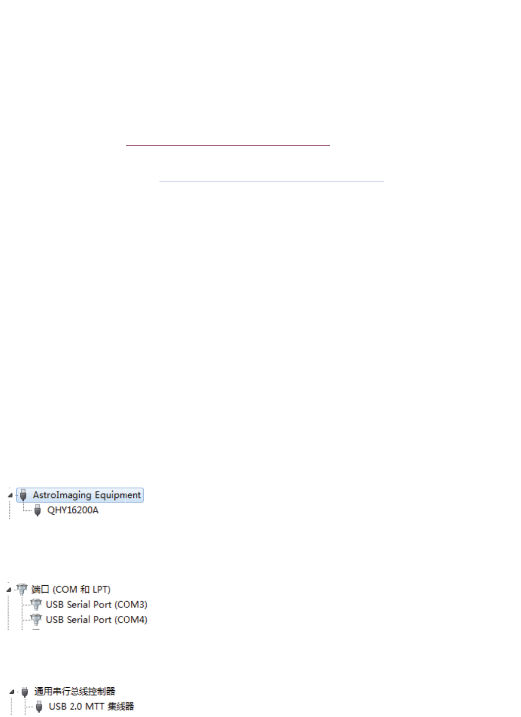
nager:
this step:
from
w
nload th
e
n
ethernet
A
and
it is useful
ay be won
s
ing the
u
ires a D
C
o
cket on
e
camera.
t
ating. Th
e
e
for
der
C
e
No
w
1.
S
2.
T
ex
p
3.
C
will
j
us
t
4.
Y
te
m
is
a
20
C
5.
Y
te
m
6.
Y
CF
W
w
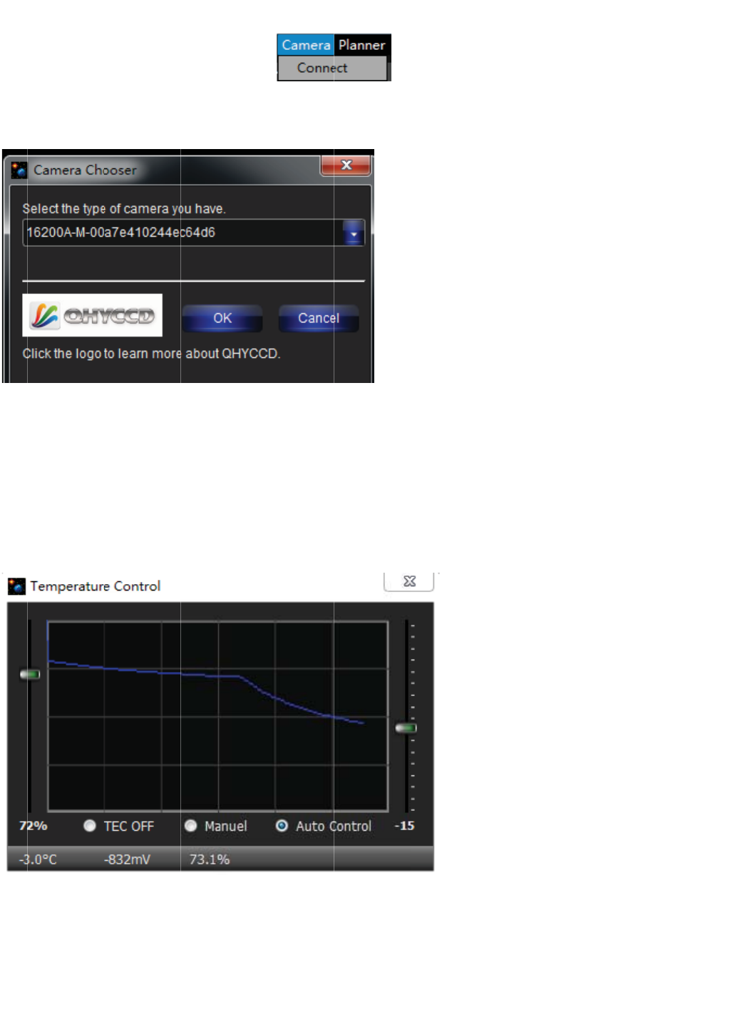
you can
S
elect Me
n
T
he camer
a
p
and.
C
lick Previ
e
off to pre
v
t
a whole
b
Y
ou can cli
c
m
perature.
a
bout 40C
b
C
environ
m
Y
ou can w
a
m
perature
c
Y
ou can cli
W
working
install the
n
u->Came
r
a
will be s
h
e
w Button.
v
ent the lig
b
lue color)
c
k menu->
Here we s
e
b
elow am
b
m
ent
you
a
it the tem
c
hanged i
s
ck menu-
>
well.
EZCAP_
Q
r
a->Conn
e
h
own in th
e
Camera
w
ht leaking.
Camera s
e
e
t it to -15
C
b
inet. It m
e
can get -2
perature f
a
s
not so fa
s
>
Camera
s
Q
T softwar
e
e
ct
e
select li
s
w
ill capture
(In curr
e
e
tup->tem
p
C
. Please
p
e
ans in 25
C
0C. You
m
a
lling dow
n
s
t. You ne
e
s
etup->Col
e
. And ru
n
s
t. Click B
u
one previ
e
e
nt firmwa
r
p
control.
p
ay attenti
C
environ
m
m
ust consi
d
n
. Since Q
e
d to be p
a
or Wheel
C
n
it.
u
tton OK.
e
w frame.
r
e version,
Select th
e
on the ma
x
m
ent
you
c
d
er some
s
HY16200
A
a
tient to w
a
C
ontrol to
s
Then the l
During t
h
the OLE
D
e
Auto Co
n
x
cooling
c
c
an get m
a
s
pare rang
A
sensor i
s
a
it more ti
m
s
et the C
F
eft tool bo
x
h
e exposu
r
D
will not s
h
n
trol and s
e
c
apability
o
a
x -15C on
e for it .
s
not small
m
e for it.
F
W positio
n
x
will be
r
e the OL
E
h
ow the te
x
e
t a target
o
f QHY162
sensor a
n
. The
n
. Check if
E
D
x
t,
00A
n
d in
the
No
t
an
d
Us
i
1. I
n
9
3.S
t
e1: The 1
2
d
the USB
i
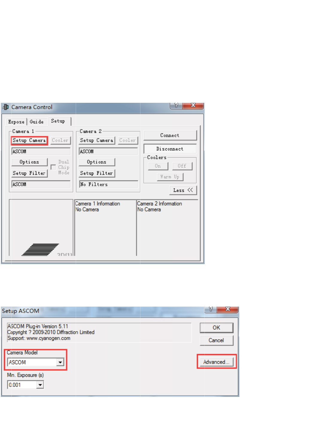
ng ASCO
n
Camera
KRKIZ'9)
5
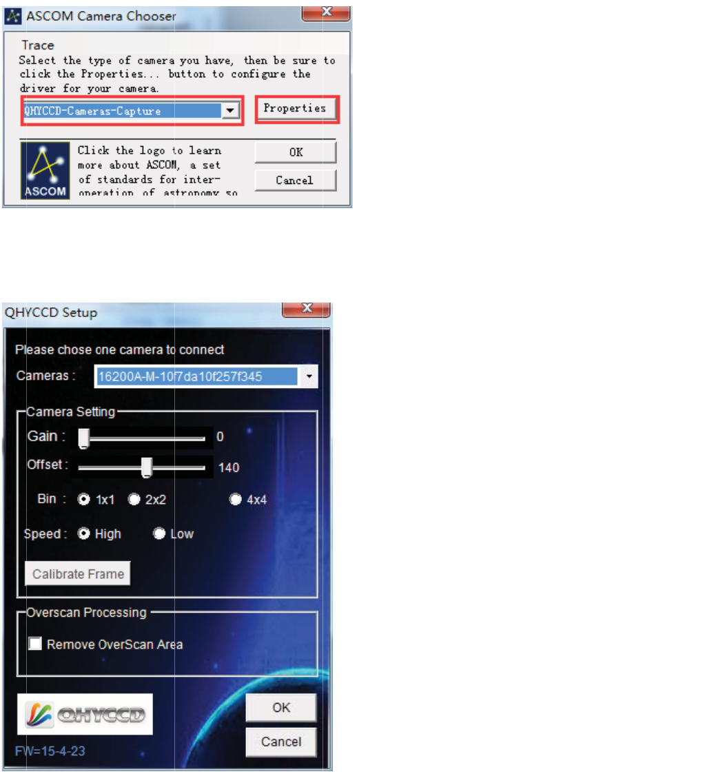
elect "QH
Y
2
V power
i
device ca
n
M and M
A
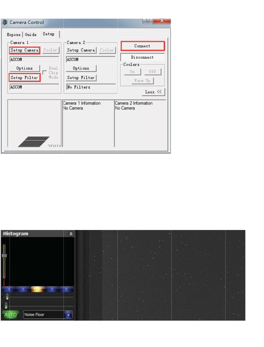
Control.
C
5
3OTZNK
Y
CCD-Ca
m
i
s necessa
n
not be fo
A
XIMDL
C
lick "Setu
p
)GSKXG3
m
era-Capt
ry for the
c
und.
p
Camera"
UJKR2OYZG
T
ure) in the
c
amera. If
y
Button
T
JIROIQ'
J
ascom ca
y
ou do no
t
J
\GTIKJ
mera list a
t
power it ,
nd click P
r
the came
r
r
operties b
r
a will not
w
utton to s
e
w
ork
e
tup.
/T
)
)
GSKXGROYZYKRKIZ
'
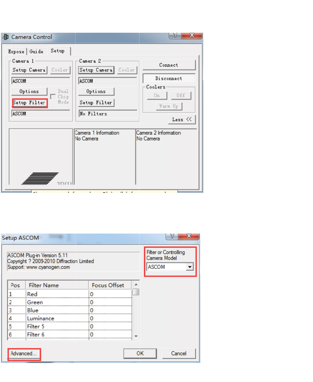
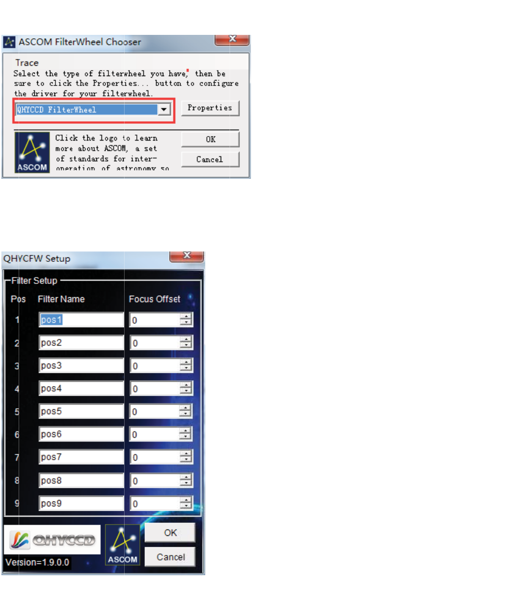
5. I
n
)N
U
n
Camera
U
UYK'9)
5
Control-C
a
5
3OTZNK
a
mera1 cli
,ORZKXUXI
U
ck "Setup
U
TZXURROTM
I
Filter" But
t
I
GSKXGSU
J
t
on
J
KRROYZ
)ROI
9KZ
[
Q'J\GTI
K
[
VZNKLORZK
K
J([ZZUT
X]NKKRVG
X
GTJYKRKIZ
X
GSKZKXY
7.?))*
,
,
ORZKX=NKKR
GTJIROIQ6XUVKXZOKY
ZUYKZ[V
)ROI
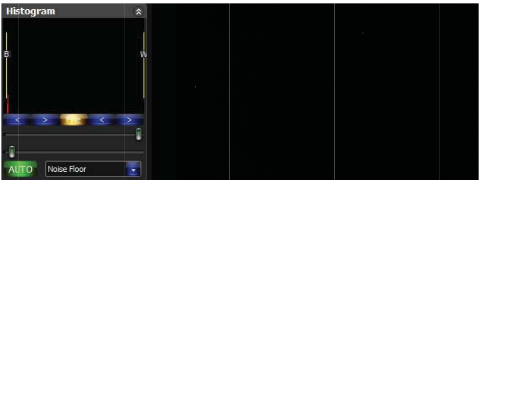
T
y
se
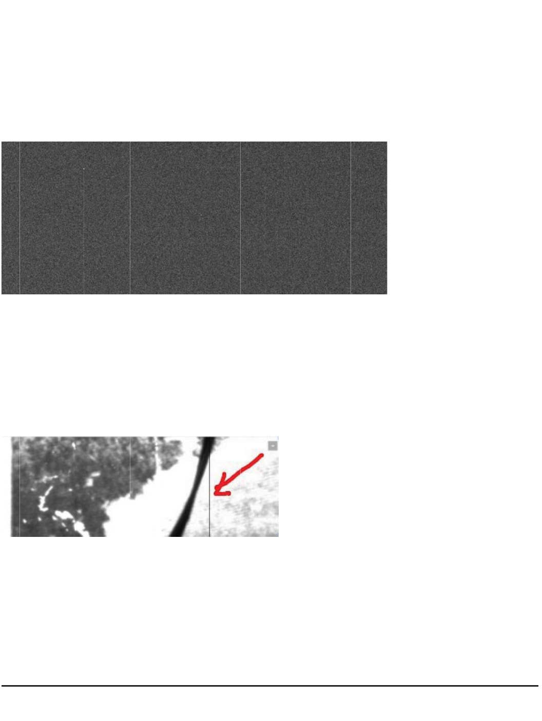
Thi
Str
e
Q)UTTKI
Z
y
pical
Q
nso
r
s is a typ
i
e
tch to ba
c
Z
ZUIUTTK
Q
HY162
i
cal Dark
F
c
kground l
e
IZHUZNIG
S
00A D
a
F
rame at
3
e
vel
S
KXGGTJLO
a
rk/Flat
/
3
00sec ex
RZKX]NKKR
/
Calibr
a
posure, -
1
a
ted Im
a
1
5C, gain
=
a
ges
w
=
0. Part o
f
w
ith Gra
f
the imag
de2
e. 1:1 zo
o
o
m
Str
e
A
t
y
on
t
cali
bri
g
Th
e
shi
e
a v
i
e
tch to Ma
x
y
pical 10s
e
t
he right o
f
bration.W
e
g
hter than
t
e
differenc
e
e
ld on it a
n
i
rtual area
x
Range
e
c 4*4binn
f
the imag
e
e
recomm
e
t
he image
e
of "Optic
n
d it does
n
and it rep
r
ing Dark
F
e
is the ov
e
e
nd you re
area.Whi
c
Black" Ar
e
n
ot sensiti
v
r
esent the
F
rame with
e
rscan ar
e
serve this
c
h is the "
O
e
a and "O
v
v
e to light,
bias .
all the re
g
e
a. The o
v
area. You
O
ptic Blac
k
v
erscan"
A
But therm
g
ion of the
v
erscan a
r
can also
s
k
" Area.
A
rea is that
al current
image. Th
r
ea is imp
o
s
ee two st
r
the "Opti
c
still exist.
.
e vertical
b
o
rtant for o
v
r
ip which i
s
c
Black" ar
e
.
The "Ov
e
b
lank ban
d
v
erscan
s
a little
e
a has a
m
e
rscan" ar
e
d
ing
m
etal
e
a is

Ab
o
Yo
u
dot
the
r
pix
e
thr
o
Thi
s
Yo
u
Thi
s
se
n
o
ut defec
t
u
may see
. Normall
y
r
mal curre
n
e
ls after th
o
ugh this
p
s
pixel ca
n
u
may see
s
is the de
f
n
sor has t
w
t
column
s
one or m
o
y
speakin
g
n
t. Beca
u
is high th
e
p
ixel.
n
be remo
v
one or m
o
f
ect colu
m
w
o grade.
g
s
o
re vertical
g
such col
u
u
se the K
A
e
rmal pixel
v
ed by dar
k
o
re black c
m
n and it c
a
g
rade1 an
d
columns.
u
mn is not
A
F frame tr
a
on the sa
m
k
frame ca
olumns w
h
a
n not be r
e
d
grade2.
F
The first
p
a defect c
a
nsfer sen
m
e colum
n
libration.
S
h
ich is not
e
moved b
y
F
rom the s
p
ixel of the
olumn. T
h
sor is tran
f
n
is getting
S
o that yo
u
full sensiti
v
y
dark fra
m
pecificatio
vertical c
o
h
is is due
t
f
erring the
thermal c
u
u
need not
v
ity to the
m
e calibrat
n of the d
a
o
lumn is a
t
o one pix
e
electron
o
u
rrent wh
e
do more t
h
light or it i
s
ion. The
K
a
tasheet, t
h
bright
e
l with hig
h
o
n pixel. Al
l
e
n transfer
e
h
ings than
s
dim to li
g
K
AF16200
h
e grade
2
h
l
the
e
d
it.
g
ht.
2
all
o
ca
n
AT
It
w
AT
so
m
o
ws some
d
n
use the "
d
T
ypical "de
f
w
ill be gon
e
T
ypical def
e
m
e defect
t
d
efect col
u
d
efect tool
f
ect" colu
m
e
after dar
k
e
ct colum
n
t
ools to re
m
u
mns. For
m
s" in som
e
m
ns cause
d
k
frame ca
l
n
with low
C
m
ove it.
m
ore infor
m
e
image pr
o
d
by a hot
p
l
ibration.
C
TE or ze
r
m
ation on
o
cess soft
w
p
ixel. Whi
c
r
o CTE. T
h
this pleas
e
w
are to re
m
c
h is tightl
y
h
is is a de
f
e
check K
A
m
ove suc
h
y
and it is n
f
ect colum
n
A
F16200
d
h
defect co
ot a really
n
. You ha
v
d
atasheet.
lumns.
defect col
u
v
e to use t
h
You
u
mn.
h
e

Use the build-in Color filter wheel
Install filters
QHY16200A has build-in five position 2inch/50mm color wheel. Please following the steps to
install them.
1. Open the camera front case. There is four M3 screws and eight M2 hexagon screws for the front
case. You can use the screw driver supplied with the camera to open it. Among the eight M2 screw
there is one shorter than all the others. Please remeber the position of this screw.
2. You will see the filter disk after remove the front case. The current disk design is suitable for both
50mm unmounted filters and the 2inch mounted filter. You can use the screw set come with the
QHY16200A to fix the filter on the disk. Please pay attention the maximum height of the filter
(excludes the 2inch thread) is 7.0mm. Please make sure the filter plus the screw does not touch
the front case and also does not touch the optic position detector board.
3. After installed the filters. You can power the camrea and connect USB to verify the colorwheel
running well. Then put the front case back.
Control filter wheel in software
In EZCAP. You can control the filter wheel rotate by select menu->camera setup->colorwheel
control
Select a number and the colorwheel will run to this position. If the number is the current position of
the colorwheel the camera will ignore of it.
In ASCOM.
Please refer to chapter " Using ASCOM and MAXIMDL" above.

Use OAG-M
QHYOAG-M and a M54 adapter come with the QHY16200A. By six M3 screws you can install
them .
The prism of the OAG may have a protect film on front surface. Please remove it before using.
You can use QHY5L-II-M as the guider. Please pay attention that you may remove the front part of
QHY5L-II-M to get the back focus short enough for this combination of OAG-M and QHY16200M. If
you are using other guider. We are not gurantte the back focus is suitable for them due to the very
short back focus of the QHY16200A.
The thinkness of QHYOAG-M is 10mm and the M53 adatper is 3mm. So the totally back focus
addon is 13mm. The QHY16200A back focus is 33.5mm. So the total back focus with
QHYOAG-M is 46.5mm.

U
s
QH
Se
r
RS
2
for
por
t
Aft
e
ch
e
Th
e
of t
h
Th
e
Ple
s
e the
O
Y16200A
r
ial Port c
o
2
32 to the
EQMOD
d
t
to EQM
O
e
r you inst
a
e
ck the C
O
e
serial po
r
h
e serical
e
PIN defi
n
ase check
O
n-Ca
m
has two o
n
o
nvertor. T
h
mount or
f
d
irectly. E
Q
O
D.
a
lled the s
y
O
M port nu
m
r
t cable is
t
port with
d
n
ition of t
h
the relati
o
m
era Se
r
n
-Camera
h
e Serical
f
ocuser. P
l
Q
MOD is T
T
y
stem dri
v
m
ber and
s
t
he option
a
d
ifferent s
o
h
e 3PIN s
o
o
n position
r
ial Po
r
Serical P
o
Port has
s
l
ease not
e
T
L level.
v
er of cam
e
s
et it in th
e
a
l
A
ccess
o
o
cket type.
o
cket
to the "re
d
r
t
o
rt. It con
n
s
tandard
R
e
it is not T
T
You can
u
e
ra, the se
e
applicati
o
o
rie for QH
Please co
d
" dot of t
h
n
ect to the
S232 leve
T
L (+5V)
v
se the lev
e
rical port
d
o
n softwar
e
Y16200A.
ntact QH
Y
h
is socket.
internal U
l (+-10V) .
v
oltage lev
e
e
l convert
o
d
river is in
s
e
.
QHYCC
D
Y
CCD for
m
SB hub vi
a
You can
c
e
l so you
c
o
r if you w
a
s
talled tog
e
D
is makin
m
ore infor
m
a
FTDI US
c
onnect to
c
an not us
e
a
nt use thi
s
e
ther. Ple
a
g some ty
p
m
ations.
B to
the
e
it
s
a
se
p
es

Other Port and Socket
In QHY16200A there is two USB HOST Port. Which is connect in the on-camera hub. You can use
this port to connect the guider or anyother USB device. The USB port can output 500mA current
each.
On top of the camera this is a "CCD Clean" Port. Normally this port is in-factory using propose.
Normally you do need to open it.
On the side of the camera there is a "Silicon gel socket". It can be used to dry the CCD chamber.
See the topic of "Drying CCD Chamber" for it.
QHY16200A has the "Trig-In" and "Trig-Out" Socket. Trig-in is the trigger input socket and allow
you send a pulse to the camera and the camera will begin to exposure. The Trig-Out socket can
output a signal to indicate the exposuring period of the camera. This two port is isolated by
RSWRFRXSOHUUHOD\
. If you need to use this two port please contact QHYCCD for details.
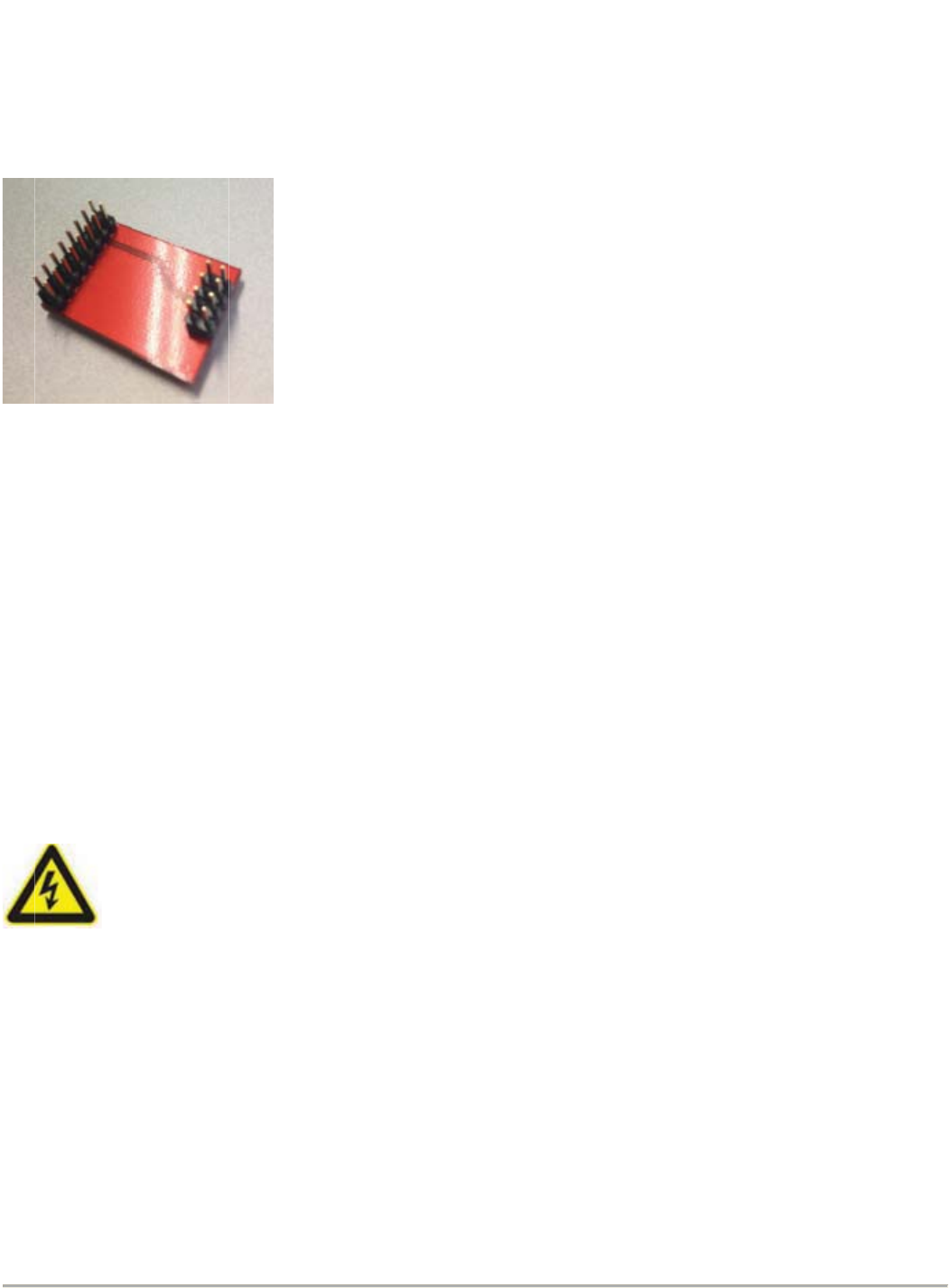
USB Bypass Board
QHY "A" series camera includes a build-in USBHUB and it can expand two USB Host and two
RS232 via a USB->Serial Port convertor. In some condition it may not work , for example, the
QHY16200A is under another USBHUB and sometimes it has conflict that cause the problems. You
can replace the HUB board with this Bypass Board by openning the case of the camera.
Here is a step by step guide of how to replace this board.
http://note.youdao.com/groupshare/?token=D1C38D9FEEDD41D2A8C7D33F9EB74294&gid=723
4866
A
ft
e
no
f
GN
Ke
e
Th
e
the
yo
u
GN
me
t
of
e
e
r you inst
a
f
unction.
D Socket
e
p the ca
m
e
QHY162
0
camera.
T
u
can inse
r
D that yo
u
t
al case et
Do
e
lectric s
h
a
lled the b
m
era groun
0
0A has a
T
he "GND
"
r
t this cabl
e
u
want to k
e
c. If you d
o
n't conne
c
h
ock .
ypass bo
a
ded with
o
GND soc
k
"
is just th
e
e
in the G
N
e
ep them
g
o
es not un
c
t this ca
b
a
rd. The c
a
o
ther devic
e
k
et for this
e
"-" of the
N
D socket
g
rounded.
derstand t
b
le to AC
a
mera's tw
o
e
is very i
m
propose.
T
12V input.
and conn
e
For exam
p
his please
power bo
a
o
USB ho
s
m
portant f
o
T
his sock
e
There is
c
e
ct anothe
r
p
le, the m
o
consult t
h
a
rd direct
s
t port and
or
get the
s
e
t is conne
c
c
able com
e
r
side of th
o
unt's met
a
h
e electric
e
ly, it will
b
two RS2
3
s
ystem sta
c
t to inter
n
e
s with th
e
e cable to
a
l case, t
e
ngineer.
b
ring the
r
3
2 port will
ble and s
a
n
al "GND"
o
e
camera a
other devi
he compu
t
r
isk
be
a
fe.
o
f
nd
ce's
t
er's

The on-camera OLED display
The on-camera OLED display is used to display some informations. This OLED is driven directly by
the applicaton software. In different software it may display different informations. In current
applications this OLED is not actived.
FAQs
1.What's the back focus of this QHY16200A
The backfocus is 33.5mm. When connect with QHYOAG-M and M54 adapter it is
33.5mm+13mm=46.5mm
Camera Maintenance
Drying the CCD Chamber
The CCD sensor is located in a CCD chamber. This chamber is airpoor and connect to the socket
of the silicon gel tube on one side of the QHY16200A case. If there is moisture and cause the CCD
sensor glass get dew. You can connect the silicon gel tube on the socket to dry it.

Please put the effective silicon gel into the silicon gel tube. Make sure this is a cotton inside to
prevent the silicon gel get into the CCD chamber.
Avoid CCD chamber optic window get dew
If the envrioment humidity very high, the optic window of the ccd chamber may get dew. The
QHY16200A has the build-in heat board on this optic window to heat the optic window to avoid it. In
most conditions it can take effection.
If the optic window still get dew please try the following method.
1.Avoid the CCD Camera face down to ground. The cold air is heavy than warm air, if you put the
camera facing down to the ground, the cold air is easy to get the optic window and cause it very
cold and get dew.
2.Increase the temperature of the CCD sensor. You can increase the CCD sensor temperature a
little to prevent the optic window get dew.
3.Check if the heat board working. If the heat board not working, the optic window is easy to get
dew. Normally the heat board can get about 65-70C in +25C enviroment . If it is not so warm, it
maybe the problem of the heat board damaged. Need to contact QHYCCD to replace one heat
board.
Clean the CCD Sensor
Normally you can use the flat frame to calibrate the dust shadow on the image. QHYCCD
does not recommand you open the ccd chamber to clean it. It may bring more dust if you
can not control the enviroment dust. It also may bring the scratch when cleanning CCD
sensor or cause some cable damaged during assembly the camera.
QHYCCD has the factory clean service. It is USD100 per time and it does not includes the
ship cost.
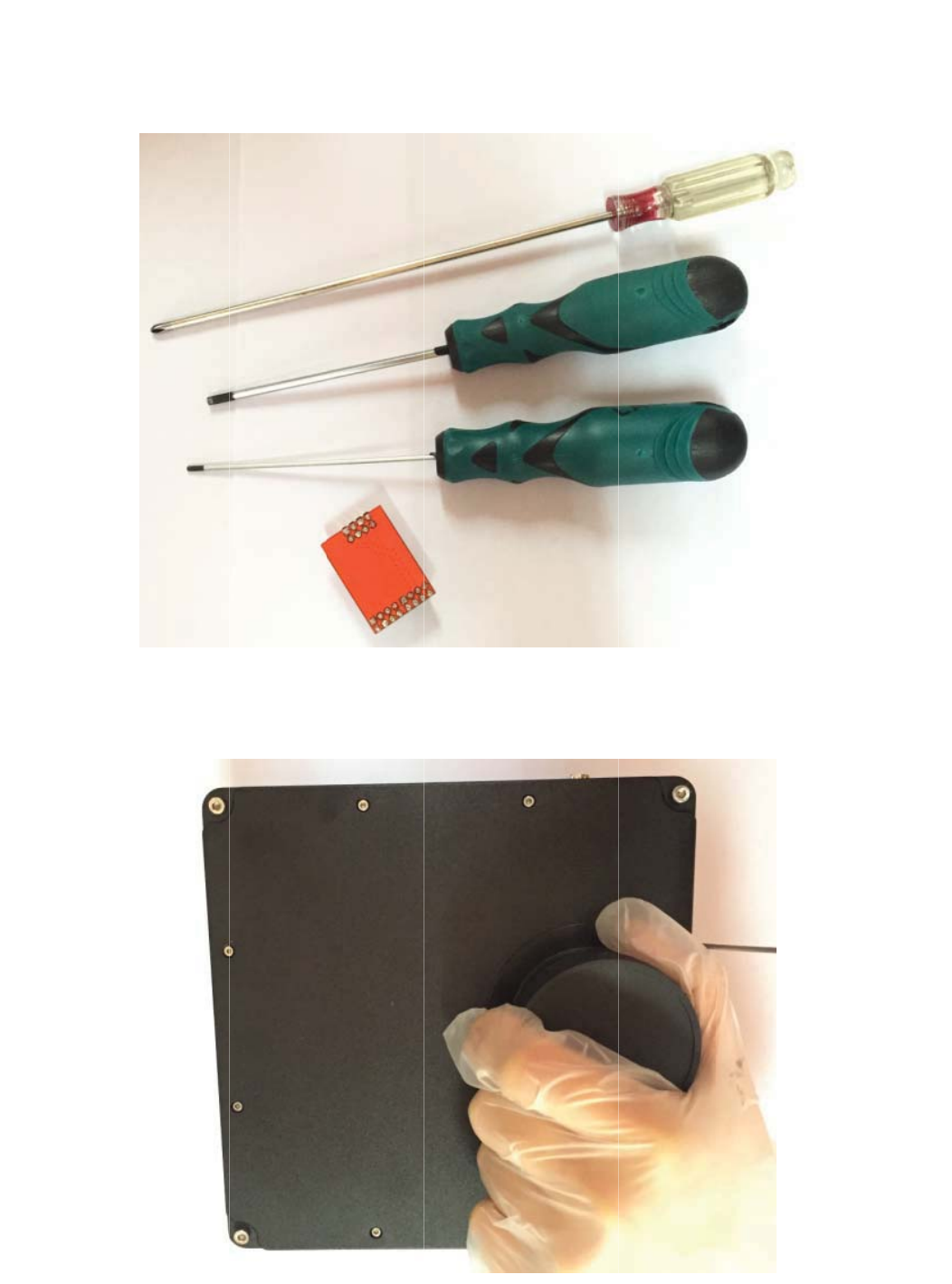
If y
Yo
u
Re
m
ou really
w
u
need pr
e
m
ove all t
h
w
ant to cl
e
pare the
h
e screws
o
ean it . Pl
e
tools by
y
o
n front of
e
ase foll
o
y
ourself t
o
the came
r
o
wing this
o
open th
e
r
a case an
step.
e
camera.
d remove
t
t
he front c
a
a
se
?U
[
ZN
K
?U
[
[
]ORRYKK
Z
K
S
[
]ORRYKK
Z
Z
]UYIXK
]
Z
NKVU]K
]
YZULO^Z
N
X6)(HU
G
N
KLORZKX]
N
G
XJ8KS
U
N
KKRIGYK
U
\KZNKZ]
ZNKSOJJ
UYIXK]
U
RKRG_KXU
L
U
LZNKVU
]
L
ZNKIGS
K
]
KX6)(H
U
K
XG[TYI
U
GXJ
XK]
8K
S
6RK
:N
K
ZN
K
S
U\KZNK
GYK[YKG
K
))*IN
G
K
Z]UYIXK
]
ZNXKKIG
H
LORSZUV
X
G
SHKXOYI
]
LUXZNK
H
RKIGXKL[R
X
UZKIZZNK
UTTKIZOT
M
YOROIUTM
K
R_
IIJING
S
M
]OZNZN
K
K
RYUIQKZ
S
HKXUVZO
I
K
YOROIUTM
K
I
]OTJU]
K
RZ[HKY
U
U
IQKZH_G
X[HHKXV
O
O
VRK8KS
U
U
\K
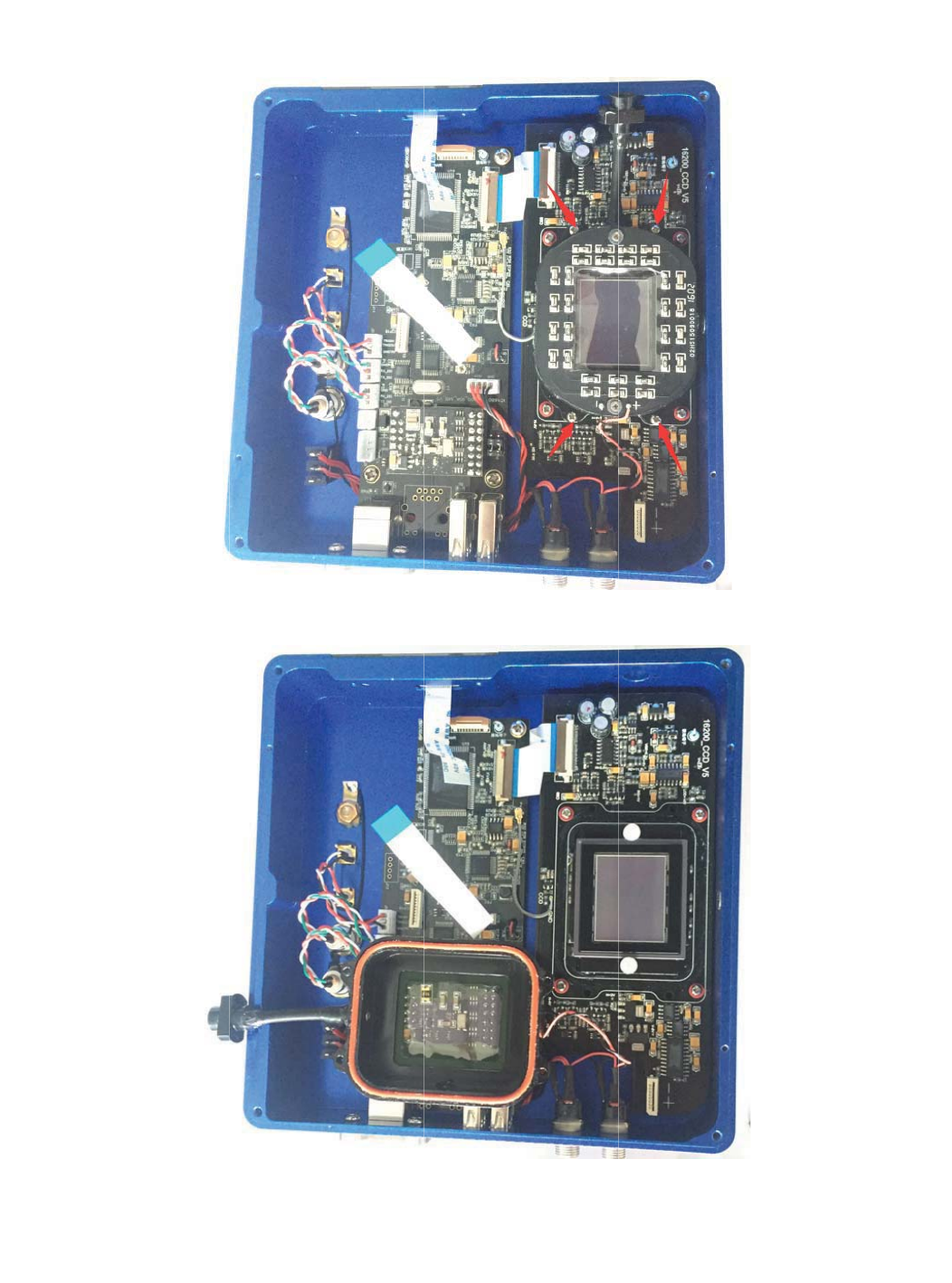
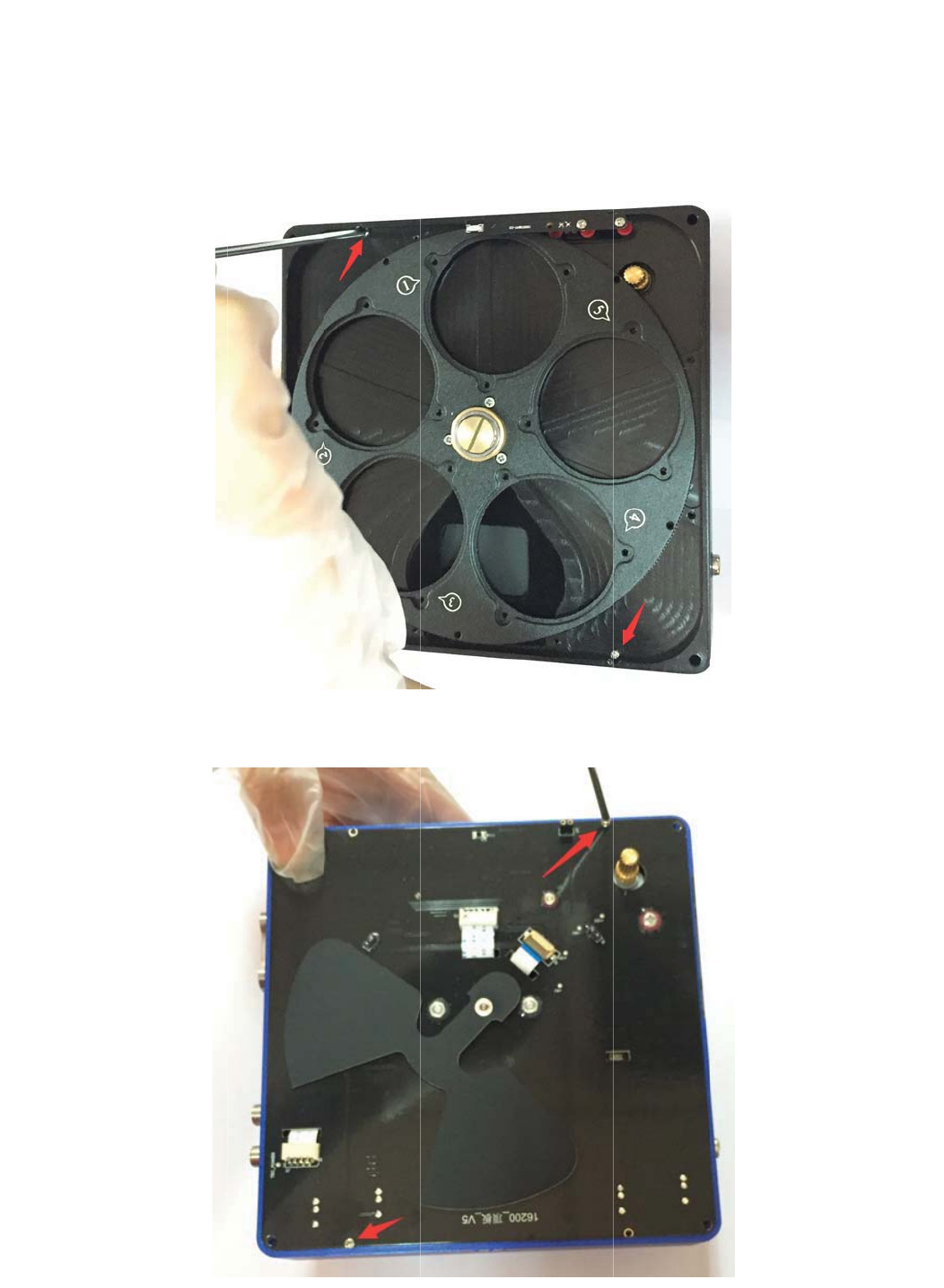
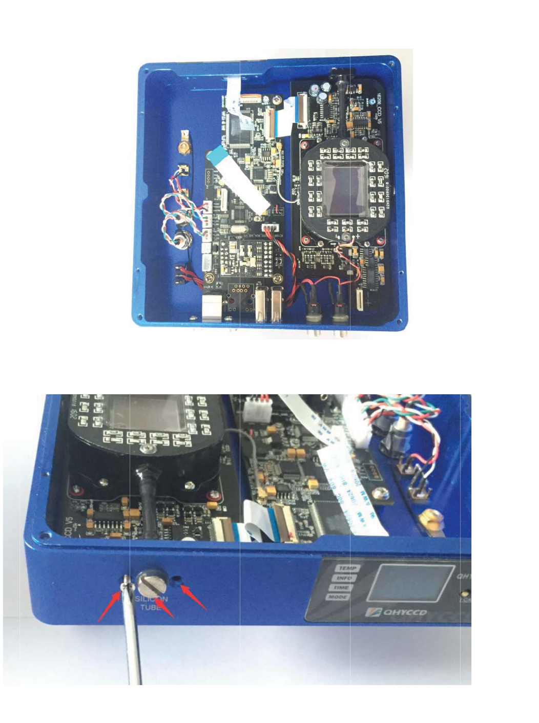
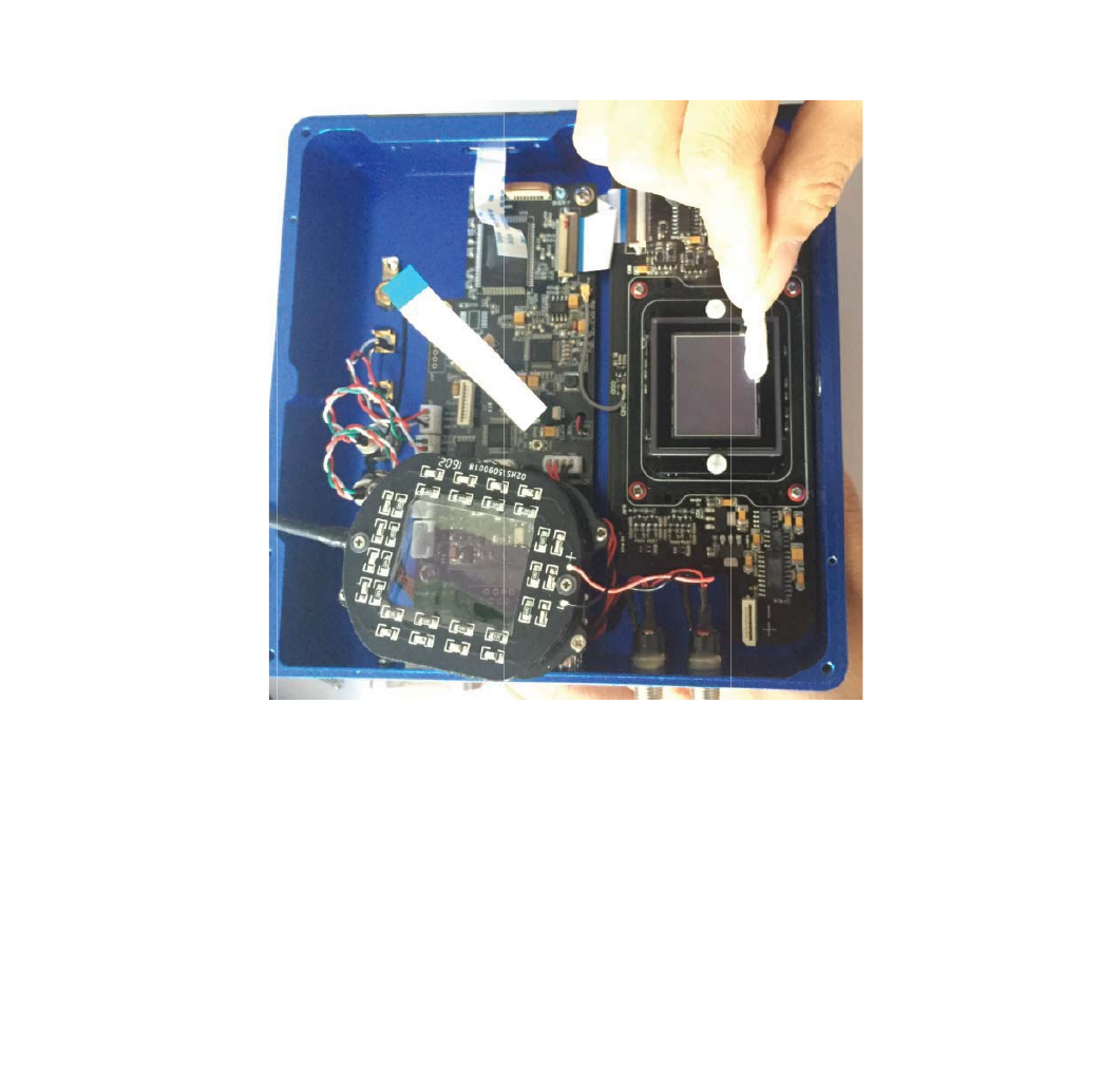
Re
m
re
m
No
w
m
ove the f
o
m
ove the f
o
w
the ccd
c
o
ur screw
o
ur screws
c
hamber i
s
for the cc
d
pointed b
y
s
removed
d
chambe
r
.
y
the red
a
. The C
C
.
There is t
a
rraow in t
h
C
D sensor
otally eigh
h
is picture
.
can be cl
e
t screws f
o
.
e
an here.
o
r the ccd
c
c
hamber.
O
O
nly
:N
K
GT
U
K
))*YK
T
U
ZNKXVXU
L
T
YUXNGYZ
N
L
KYYOUTGR
Z
N
K'8IUG
Z
UURYROQK
ZOTM6RKG
ZNK*29
8
YKIRKGTO
Z
8
YKTYUXIR
Z
IGXKL[RR
_
KGTZUURY
_
H_[YOTM
ZNKRKTY
V
V
GVKXUX
This device complies with Part 15 of the FCC Rules. Operation is subject to the following two
conditions: (1) this device may not cause harmful interference, and (2) this device must accept any
interference received, including interference that may cause undesired operation.
Notice

Changes or modifications not expressly approved by the party responsible
for compliance could void the user's authority to operate the equipmentDŽ
NOTE: This equipment has been tested and found to comply with the
limits for a Class B digital device, pursuant to Part 15 of the FCC Rules.
These limits are designed to provide reasonable protection against
harmful interference in a residential installation. This equipment
generates, uses and can radiate radio frequency energy and, if not
installed and used in accordance with the instructions, may cause harmful
interference to radio communications. However, there is no guarantee
that interference will not occur in a particular installation. If this equipment
does cause harmful interference to radio or television reception, which
can be determined by turning the equipment off and on, the user is
encouraged to try to correct the interference by one or more of the
following measures:
-- Reorient or relocate the receiving antenna.
-- Increase the separation between the equipment and receiver.
-- Connect the equipment into an outlet on a circuit different
from that to which the receiver is connected.
-- Consult the dealer or an experienced radio/TV technician for
help.
FCC ID: 2AJFC-16200A
This device complies with Part 15 of the FCC Rules. Operation is
subject to the following two conditions: (1) this device may not
cause harmful interference, and (2) this device must accept any
interference received, including interference that may cause
undesired operation.