LogiTag Systems 1149466 4 channel RFID reader with CAN bus User Manual Users manual
LogiTag Systems Ltd. 4 channel RFID reader with CAN bus Users manual
Contents
- 1. Users Manual
- 2. Users manual
Users manual
Holmium Surgical Lasers
Operator's Manual
Lumenis PULSE
50H/100H
®TM
Lumenis® PulseTM 50H / 100H Laser Systems
UM-20006520DE, Rev. A Page 2
This manual is copyrighted with all rights reserved. Under copyright laws,
this manual may not be copied in whole or in part or reproduced in any
other media without the express written permission of Lumenis. Permitted
copies must carry the same proprietary and copyright notices as were
affixed to the original. Under the law, copying includes translation into
another language.
Please note that while every effort has been made to ensure that the data
given in this document is accurate, the information, figures, illustrations,
tables, specifications, and schematics contained herein are subject to
change without notice.
Lumenis, the Lumenis Logo, Pulse 50 and Pulse 100 are trademarks or
registered trademarks of Lumenis.
Copyright © Lumenis (Germany) GmbH
Catalog Part Number: UM-20006520DE
July 2015
Revision A
Manufactured by Lumenis (Germany) GmbH
Heinrich-Hertz-Strasse 3
D-63303 Dreieich-Dreieichenhain
Germany
Tel: +49 (0) 6103.8335.0
Directive 2012/19/EU on Waste Electrical and Electronic Equipment
(WEEE)
In accordance with Directive 2012/19/EU on Waste Electrical and
Electronic Equipment (WEEE), any item which is marked with the
crossed-out wheelie bin symbol must not be disposed of as unsorted
municipal waste, but segregated from other waste types for eventual
treatment and recovery at an approved recycling facility.
By returning waste electrical and electronic equipment via the correct
segregated disposal channel, users can ensure the environmentally sound
treatment and disposal of the waste equipment, thereby reducing the
potential for any environmental or health risks that could arise as a result
of incorrect disposal.
Lumenis provides web-based collection, recycling and reporting
arrangements to the business end-user for equipment marked with the
crossed-out wheelie bin.

Lumenis® PulseTM 50H / 100H Laser Systems Table of Contents
UM-20006520DE, Rev. A Page 3
Table of Contents
Table of Contents ......................................................................................................... 3
Chapter 1: Introduction ............................................................................................... 7
Reference to the Lumenis Pulse Systems ..................................................................... 8
Manual Conventions ...................................................................................................... 8
System Description and Main Features ......................................................................... 9
Laser System Console .................................................................................10
Touch-Screen Control Panel ........................................................................10
User Interface Language ..............................................................................10
Footswitch ....................................................................................................10
Optical Fibers ...............................................................................................11
Component Checklist ................................................................................................... 11
Chapter 2: Theory of Operation ................................................................................ 12
Laser Power Parameters ............................................................................................. 12
Chapter 3: Safety ....................................................................................................... 14
Introduction .................................................................................................................. 14
Optical Hazards ........................................................................................................... 14
Laser Safety Eyewear ..................................................................................14
Additional Ocular Protection .........................................................................15
Electrical Hazards ........................................................................................................ 16
Fire Hazards ................................................................................................................ 16
Additional Safety Considerations ................................................................................. 16
Protecting Non-Target Tissues .................................................................................... 17
Laser Emission Indicators ............................................................................................ 18
Warning, Certification and Identification Labels ........................................................... 18
Explanation of the symbols used in the labels .............................................19
Chapter 4: Clinical Guide .......................................................................................... 22
Indications for Use ....................................................................................................... 24
Contraindications ......................................................................................................... 24

Lumenis® PulseTM 50H / 100H Laser Systems Table of Contents
UM-20006520DE, Rev. A Page 4
Specific Contraindications in Urology ..........................................................24
Specific Contraindications in Gynecology ...................................................24
Warnings and Precautions ........................................................................................... 24
Complications .............................................................................................................. 25
Detailed Indications for Use ......................................................................................... 26
Urology ........................................................................................................27
Arthroscopy .................................................................................................28
General Surgery ..........................................................................................29
ENT Surgery ................................................................................................30
Gynecological Surgery ................................................................................30
Gastroenterology Surgery ...........................................................................31
Pulmonary Surgery ......................................................................................31
Dermatology and Plastic Surgery ................................................................32
Chapter 5: Preparing the System for Use ................................................................ 33
Moving the Laser System Console .............................................................................. 34
Connecting the Footswitch ........................................................................................... 35
Connecting the External Door Interlock Connector ...................................................... 36
Plugging in the Main Power Cable ............................................................................... 37
Connecting the Optical Fiber ....................................................................................... 38
SIS (Secured Identification System) Technology ........................................41
Chapter 6: Operating Instructions ............................................................................ 42
Emergency Stop Switch ............................................................................................... 42
Safety Eyewear ............................................................................................................ 43
Verification of Connections .......................................................................................... 43
Powering on the System .............................................................................................. 43
Restarting the Laser System ........................................................................................ 43
Treatment Screen Description ..................................................................................... 44
Laser Emission Indicators ...........................................................................46
Intra-Operative Instructions .......................................................................................... 47
Post-Operative Instructions .......................................................................................... 49
Moving the Laser Console ........................................................................................... 50

Lumenis® PulseTM 50H / 100H Laser Systems Table of Contents
UM-20006520DE, Rev. A Page 5
Chapter 7 - Troubleshooting and Maintenance ....................................................... 51
Handling Error Messages and Notifications ................................................................. 51
Troubleshooting ........................................................................................................... 52
Initialization Error Message Appears ...........................................................52
System Does Not Turn On ...........................................................................52
Inadequate or No Aiming Beam ...................................................................52
No Laser Energy Emission ..........................................................................52
“Popping” or “Tapping” Coming Sound from the Fiber Port .........................53
Fiber Burn Back ...........................................................................................53
Unrecognized Fiber .....................................................................................53
A Notification or Error Message Appears on the Control Panel ...................53
System Overheats .......................................................................................54
Message Appears: Attach an Authorized Fiber ...........................................54
Message Appears: Attach fiber ....................................................................54
Message Appears: Attach footswitch ...........................................................54
Message Appears: Check footswitch ...........................................................55
Message Appears: Check interlock .............................................................55
Message Appears: Insert debris shield ........................................................55
Message Appears: No lasers .......................................................................55
Message Appears: Energy high ...................................................................55
Message Appears: Energy low ....................................................................55
Message Appears: Rate high .......................................................................56
Message Appears: Rate low ........................................................................56
Routine Periodic Maintenance ..................................................................................... 57
Hospital/Clinic Staff Maintenance ................................................................................ 58
Visual Inspection ..........................................................................................58
Routine Exterior Cleaning ............................................................................58
Remote Interlock Check ...............................................................................58
Emergency Stop Button Check ....................................................................59
Inspect the Debris Shield .............................................................................59
Change the Debris Shield Optic ..................................................................62
Professional Maintenance ............................................................................................ 63

Lumenis® PulseTM 50H / 100H Laser Systems Table of Contents
UM-20006520DE, Rev. A Page 6
Energy Detectors Calibration 63
Chapter 8: System Requirements and General Information .................................. 65
Installation .................................................................................................................... 65
Accessories .................................................................................................................. 65
Tools (Optional) ........................................................................................................... 66
Electrical Requirements ............................................................................................... 66
Electrical Utilities .......................................................................................................... 66
Systems Designed For Use Outside of Europe ...........................................66
Systems Designed For Use in European Communities Under the MDD .....66
External Door Interlock Pin Assignments .....................................................67
Compliance With International Standards .................................................................... 68
Emergency Stop Button ...............................................................................68
Keyswitch .....................................................................................................68
Laser Emission Indicators ............................................................................68
External Door Interlock .................................................................................68
Protective Housing .......................................................................................68
Safety Shutter ...............................................................................................68
Manual Reset ...............................................................................................69
Electronic Fault Detection Circuitry ..............................................................69
Safety Interlocks ...........................................................................................69
Precision of Displayed Values ......................................................................69
Space Requirements ................................................................................................... 69
System Specifications .................................................................................................. 70
Laser Safety Eyewear ..................................................................................71
Replacement Parts Part Numbers ...............................................................71
Compatible Optical Fibers ...........................................................................71
Decontamination of Returned Equipment .................................................................... 72
Customer Service and Warranty .................................................................................. 72
Appendix A: EMC Guidance and Manufacturer's Declaration ............................... 73
Electromagnetic Emissions .......................................................................................... 73
Electromagnetic Immunity ........................................................................................... 74
Recommended Separation Distances ......................................................................... 76
Lumenis® PulseTM 50H / 100H Laser Systems Chapter 1: Introduction
UM-20006520DE, Rev. A Page 7
Chapter 1: Introduction
The Lumenis Pulse 50H and Lumenis Pulse 100H holmium laser systems
provide utility in urology, orthopedics, ENT, gynecology and general
surgery applications. Fiber delivery of holmium laser energy is ideal for
minimally invasive surgery.
WARNING:
• Lasers generate a highly concentrated beam of light which may cause
injury if improperly used. To protect the patient and operating
personnel, the entire laser system and the appropriate optical fiber
operator manuals, including all Safety and Regulatory sections, should
be carefully read and comprehended before operation.
• Lumenis medical lasers and laser optical fibers are intended solely for
physicians trained in the use of these instruments.
In the USA:
CAUTION:
US federal law restricts this device to sale by or on the order of a
physician.
Lumenis lasers and delivery systems are precision medical instruments.
They have undergone extensive testing and with proper handling are
useful and reliable clinical instruments. If you have questions regarding
your laser system or optical fiber, contact Lumenis Customer Service.
NOTE:
All of the screen captures shown in this manual are for illustration only
and may differ depending on the specific version of your system and the
language selected.
Lumenis® PulseTM 50H / 100H Laser Systems Reference to the Lumenis Pulse Systems
UM-20006520DE, Rev. A Page 8
Reference to the Lumenis Pulse Systems
This operator's manual discusses two laser systems: the Lumenis Pulse
50H system and the Lumenis Pulse 100H system.
• In many places the instructions in this manual are identical for both
systems. In these instances the manual refers generically to the
System.
• In instances where the instructions are explicit to one or the other
system, the manual refers specifically to the Pulse 50H system or to
the Pulse 100H system.
Manual Conventions
NOTE:
A Note is a statement that alerts the operator to particularly important
information.
CAUTION:
A Caution is a statement that alerts the operator to the possibility of a
problem with the device associated with its use or misuse. Such problems
include device malfunction, device failure, and damage to the device or
other property. The caution statement includes the precaution that should
be taken to avoid the hazard.
WARNING:
A Warning is a statement that alerts the operator to the possibility of
injury, death, or serious adverse reactions associated with the use or mis-
use of the device.
Lumenis® PulseTM 50H / 100H Laser Systems System Description and Main Features
UM-20006520DE, Rev. A Page 9
System Description and Main Features
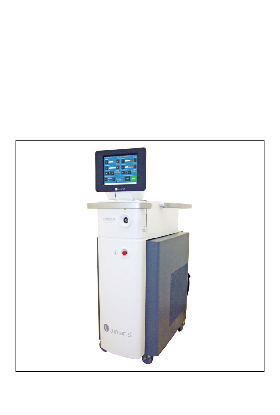
The Lumenis Pulse 50H or Pulse 100H laser system comprises the
following main components and features:
• Laser system console
• Rotatable control panel with touch-screen technology
• Dual-pedal footswitch
• Security Identification System (SIS) technology
• Green aiming beam
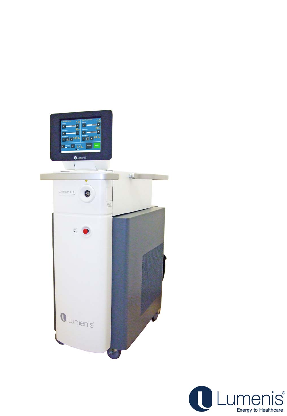
Figure 1: Lumenis Pulse 50H / Pulse 100H Laser System Console
Lumenis® PulseTM 50H / 100H Laser Systems Laser System Console
UM-20006520DE, Rev. A Page 10
Laser System Console
The laser system console houses the control screen, the laser control
keyswitch, emergency stop knob, main On/Off switch, control electronics,
laser source and associated optics, and power supply. An optical fiber
attaches to the fiber connection port on the front of the console, enabling
laser energy to be delivered to the treatment site.
Touch-Screen Control Panel
The control panel is an LCD monitor with touch-screen technology that
allows the operator to select treatment settings outside of the sterile field.
User Interface Language
To change the language displayed in the user interface screens consult
with Lumenis Customer Service.
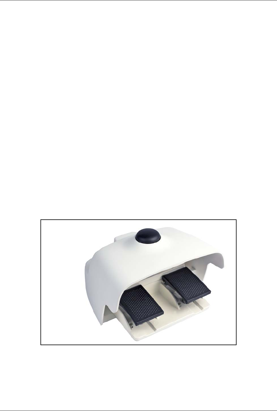
Footswitch
The dual-pedal footswitch activates the laser treatment beam when
pressed, and offers the ability to select treatment from two sets of
parameters by using the left or the right foot-pedal. It also incorporates a
Standby/Ready foot-operated button.
Figure 2: Dual-Pedal Footswitch

Lumenis® PulseTM 50H / 100H Laser Systems Optical Fibers
UM-20006520DE, Rev. A Page 11
Optical Fibers
A variety of optical fibers are available for use with the Lumenis Pulse
50H and Lumenis Pulse 100H laser systems. Lumenis fibers incorporate
Security Identification System (SIS) technology. Refer to the appropriate
optical fiber’s instruction guide for specific operating instructions.
Component Checklist
• Lumenis Pulse 50H or Pulse 100H laser system console.
• Detachable dual-pedal footswitch.
• External door interlock connector.
•Keys
• Operator’s manual.

Lumenis® PulseTM 50H / 100H Laser Systems Chapter 2: Theory of Operation
UM-20006520DE, Rev. A Page 12
Chapter 2: Theory of Operation
A laser, an acronym for Light Amplification of Stimulated Emission of
Radiation, produces a highly concentrated beam of light of a given
wavelength. Laser energy is generated by converting electrical energy to
light energy using a flashlamp. The flashlamp energy is then used to
excite the lasing medium, in this case a holmium YAG crystal rod. The
laser energy is amplified in the laser resonator cavity and a small portion
of the energy is allowed to leak out as the laser working beam.
The Pulse 50H or 100H holmium laser system emits a laser beam at a
wavelength of 2100nm. This wavelength is strongly absorbed by water in
tissue. Since soft tissue is comprised primarily of water, holmium laser
energy can be used effectively for excision, incision, ablation, and
vaporization when in direct contact with soft tissue and for coagulation
when in near contact with soft tissue. Calculi (stones) also contain a
sufficient amount of water that absorbs the laser energy leading to
lithotripsy.
When working in liquid environment the holmium laser energy provides
additional safety, since laser energy will be absorbed by the surrounding
liquid, limiting its reach to non-target tissue.
The holmium laser wavelength falls in the near-infrared region of the
electromagnetic spectrum. This wavelength is invisible to the human eye.
Therefore, a low-power, visible aiming beam is used to verify the laser’s
target tissue.
Laser Power Parameters
Tissue laser interaction is primarily governed by the laser wavelength and
the target tissue absorption coefficient at that wavelength, defining the
effectiveness of the laser energy absorption in the target tissue. However
additional characteristics of the specific laser system affect the laser tissue
interaction.
Pulsed lasers (such as the holmium laser) deliver an average power
(measured in Watts) that is achieved by multiplying the laser energy
emitted during each pulse (measured in Joules) and the frequency at
which these pulses are delivered (measured in Hertz).
The Lumenis Pulse 50H or Pulse 100H can deliver a maximum average
power of 50W or 100W respectively obtained, i.e., by delivery of 2 x 25 Hz.

Lumenis® PulseTM 50H / 100H Laser Systems Laser Power Parameters
UM-20006520DE, Rev. A Page 13
Holmium laser systems can deliver the same average power at different
settings to achieve different laser tissue effect. Changing the energy of
each pulse can be described as the “bite size” of the laser effect, whereas
the frequency as the “bite rate”. For example, setting the system at 50W
can be performed using the following sets of parameters: 2.5J at 20Hz or
2.0J at 25Hz.
When working with calculi, for example, these different settings may
affect the stone by breaking the stone into particles versus disintegrating
the stone into fine dust. The selection of the appropriate energy and
frequency settings is dependent on the procedure and specific target
tissue.
Each pulse is delivered at a specific time frame, leading to fast heating
rise in temperature of the target tissue. By increasing the pulse duration,
the time frame of energy delivery to the tissue changes and thereby
changing the temperature profile of the tissue. A different temperature
profile may lead to a heating rather than a vaporizing effect and is useful
for example when blood vessel coagulation is desired.
The selection of appropriate power parameters and optical fiber is
dependent on the procedure and the specific patient condition. It is
recommended that you become familiar with laser characteristics and
techniques by attending courses and consulting with colleagues in order to
utilize the lasers capabilities in a safe manner.

Lumenis® PulseTM 50H / 100H Laser Systems Chapter 3: Safety
UM-20006520DE, Rev. A Page 14
Chapter 3: Safety
Introduction
This chapter contains important safety information related to the use of
the laser system. All operating personnel should familiarize themselves
with the contents of this chapter before operating the laser system.
Users must take precautions to prevent exposure of laser energy to the
eyes and skin from either direct or diffusely reflected laser beams, except
as a therapeutic application. Additional precautions must be taken to
prevent fire, electrical injury, and explosion.
CAUTION:
Read this operator’s manual carefully. Use of controls or adjustments or
performance of procedures other than those specified herein may result in
hazardous laser radiation exposure.
Optical Hazards
Laser Safety Eyewear
The following specifications were calculated for this systems:
All personnel who are within the Nominal Ocular Hazard Distance are
considered to be within the controlled area and must wear eye protection
according to the following specifications:
WARNING:
Select the appropriate laser safety eyewear for the specific laser in use, by
verifying that the above specifications are indicated on the laser safety
eyewear that is at your disposal.
System
Maximum Permissible Exposure Nominal Ocular Hazard Distance
Lumenis Pulse 50H 2 mJ/cm21.9 meters
Lumenis Pulse 100H 2 mJ/cm21.9 meters
System
W
avel
en
g
t
h Used
Minimum Optical Density (OD) Protection Level
Lumenis Pulse 50H
H
o
:
Y
A
G
(2.1
µm) 3.0
DI LB3
Lumenis Pulse 100H
H
o
:
Y
A
G
(2.1
µm) 3.0
DI LB3

Lumenis® PulseTM 50H / 100H Laser Systems Additional Ocular Protection
UM-20006520DE, Rev. A Page 15
Laser safety eyewear must meet the requirements as per EN207 and
ANSI Z136.1.
In addition to providing the required laser safety eyewear, take the
following steps to secure the treatment room, or the controlled area:
1. To alert personnel before they enter the controlled area, place a
warning sign on the outside of the treatment room door when the laser
is in use.
2. Close the treatment room door during operation of the laser.
3. External door interlocks that automatically disable the laser when the
treatment room door is opened may be installed.
4. Depending on the procedure, the physician must protect the patient’s
eyes with either laser safety eyewear or one of the following items
moistened with a nonflammable solution: thick cloth, eye pads, or
gauze 4 x 4s. For periorbital treatment, the physician must protect the
patient with dulled, metal eye shields.
Additional Ocular Protection
WARNING:
• Always verify that the optical fiber is properly connected to the laser
system. An improper connection may result in an inadvertent
secondary laser beam. Severe eye or tissue damage could occur.
• Never substitute prescription eyewear for the appropriate laser safety
eyewear, as severe eye damage could occur. Prescription eyewear can
concentrate the laser light to the eye and/or can be shattered by a high
power density beam, possibly causing severe eye damage.
• Use caution when performing procedures around the eyes. Severe and
irreversible eye damage and scarring may occur from direct or indirect
exposure to the treatment beam. The predominant ocular structures at
risk are dependent on the laser wavelength in use. In general, visible
and near-infrared wavelengths are most damaging to the retina, while
ultraviolet or infrared wavelengths are most damaging to the cornea
and sclera. Severity of injury depends on how concentrated or diffused
the treatment beam is and the length of exposure. A thorough
understanding of the specific ocular risks and safety precautions for
each laser wavelength is necessary to ensure the safety of the patient
and operating personnel.
• Never look directly into any optical fiber, handpiece, probe or laser
system aperture while the laser system is energized. Severe eye
damage could occur. Turn off the laser system before inspecting any
optical fiber or laser components.
Lumenis® PulseTM 50H / 100H Laser Systems Electrical Hazards
UM-20006520DE, Rev. A Page 16
Electrical Hazards
WARNING:
• Never open the laser system console protective covers. Opening the
covers will expose the user to high voltage components, the laser
resonator, and possible laser radiation. Only Lumenis-certified service
technicians are qualified to work inside the console.
• Do not operate the laser system if any of the cords are faulty or frayed.
The laser system should undergo routine inspection and maintenance
per Lumenis manufacturer’s recommendations and institutional
standards.
• To avoid risk of electric shock, this equipment must only be connected
to a supply mains with protective earth.
Fire Hazards
WARNING:
• Do not use this device in the presence of flammables or explosives,
such as volatile anesthetics, alcohol, certain surgical preparation
solutions, and similar substances. An explosion and/or fire could
occur.
• The treatment beam can ignite most non-metallic materials. Use fire
retardant drapes and gowns. The area around the treatment site can be
protected with towels or gauze sponges moistened with sterile saline
solution or sterile water. If allowed to dry, protective towels and
sponges can increase the potential fire hazard. A UL-approved fire
extinguisher and water should be readily available.
• When performing procedures in the perianal area, the flammability of
methane gas must be considered. Moistened sponges should be
inserted into the rectum.
Additional Safety Considerations
CAUTION:
Smoke evacuation may be required if using the laser system in open-air
procedures.
Lumenis® PulseTM 50H / 100H Laser Systems Protecting Non-Target Tissues
UM-20006520DE, Rev. A Page 17
Protecting Non-Target Tissues
WARNING:
• When using an optical fiber, always inspect it to ensure that it has not
been kinked, punctured, fractured, or otherwise damaged. The optical
fiber may be damaged if stepped on, pulled, left lying in a vulnerable
position, kinked, or tightly coiled. Do not clamp the optical fiber with
a hemostat or other instruments. If sterile tape is used, always remove
the tape before lifting the optical fiber. A damaged optical fiber may
cause accidental laser exposure or injury to the treatment room
personnel or patient, and/or fire in the treatment room.
• Never deliver the treatment beam to the target tissue if the aiming
beam integrity has not been verified; the optical fiber may be
damaged. A damaged optical fiber may cause accidental laser
exposure to the treatment room personnel or patient, and/or fire in the
treatment room.
• Except during actual treatment, the laser system must always be in
Standby mode. Maintaining the laser system in Standby mode
prevents accidental laser exposure if the footswitch is inadvertently
pressed.
CAUTION:
• To prevent accidental laser discharge, always make sure that the
footswitch is not being operated while connecting the optical fiber.
• Never place hands or other objects in the path of the laser beam.
Severe burns could occur.
• Only the person directing the aim of the laser beam should have access
to the laser system footswitch. Use caution pressing the laser system
footswitch when it is in proximity to footswitches for other equipment.
Verify the footswitch pressed is the correct one in order to avoid
accidental laser exposure.
• Never discharge the laser system without a target to absorb it and
without consideration given to what lies behind the target. Place
energy-absorbing material behind the target tissue when aiming the
laser at an oblique target.

Lumenis® PulseTM 50H / 100H Laser Systems Laser Emission Indicators
UM-20006520DE, Rev. A Page 18
Laser Emission Indicators
• An audible signal is emitted during lasing. A different audible sound
is used for the left and right pedals.
• When lasing, a lasing emission indicator appears on the screen.
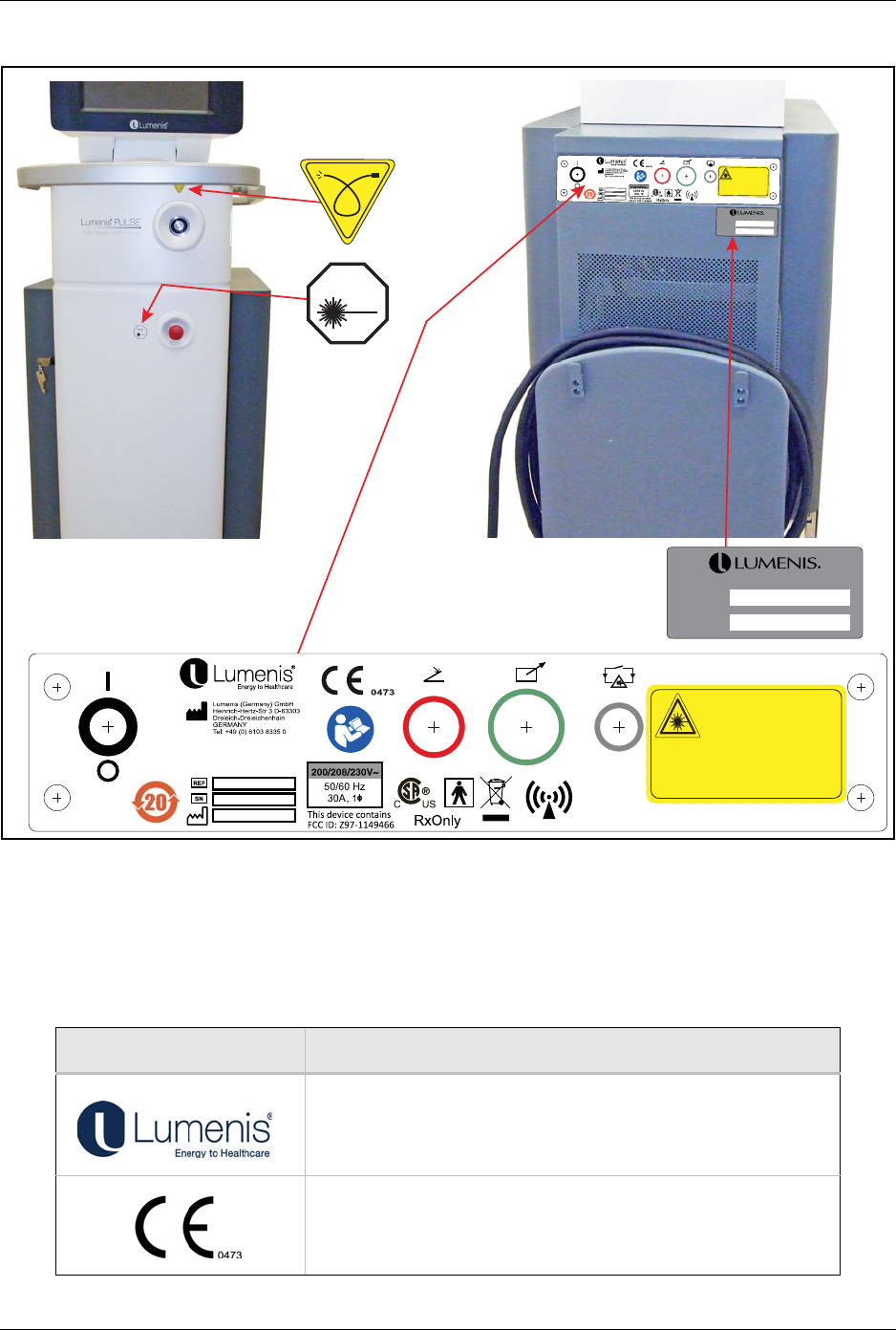
Warning, Certification and Identification Labels
As required by national and international regulatory agencies, appropriate
warning labels have been mounted in the specified locations.
Figure 3 displays the identification and certification labels affixed to the
system and the symbols displayed in the labels:
Lumenis® PulseTM 50H / 100H Laser Systems Explanation of the symbols used in the
UM-20006520DE, Rev. A Page 19
Figure 3: Location of Regulatory Compliance Labels
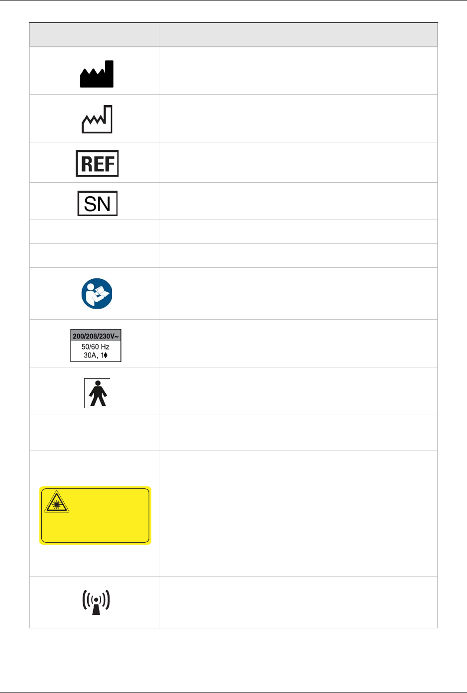
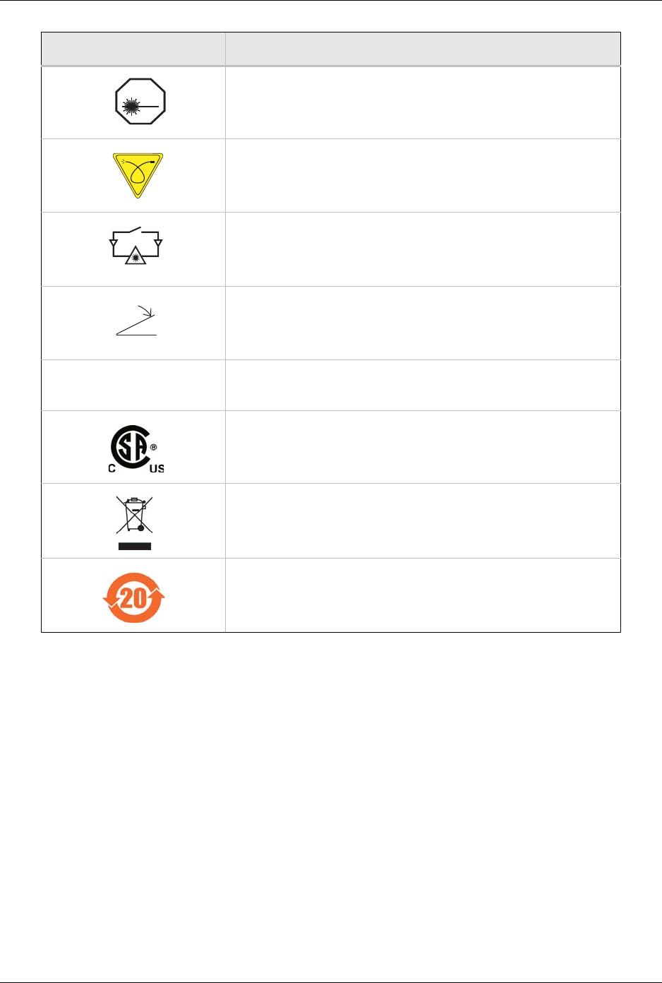
Explanation of the symbols used in the labels
The labels located on the system's front and rear panels contain the following information:
Symbol Description
Lumenis, Energy to Healthcare
CE Compliance
STOP
SYSTEM
SERIES
SYSTEM
SERIES
LASER CLASS 4/IV
Holmium: YAG: 2.1 μm, 3.5 J max.
600 μs pulse max.
LASER CLASS 3R/Illa
DSPP Laser: 532 nm, 5 mW max. CW
VISIBLE AND INVISIBLE LASER RADIATION
AVOID EYE OR SKIN EXPOSURE TO DIRECT
OR SCATTERED RADIATION
CLASS 4 LASER PRODUCT per IEC/EN 60825-1/2007
CLASS IV LASER PRODUCT per 21 CFR 1040.10 AND 1040.11
LB -20001720_A
except for deviations pursuant to Notice 50, dated June 24, 2007
LB-20001260DE_A
Lumenis® PulseTM 50H / 100H Laser Systems Explanation of the symbols used in the
UM-20006520DE, Rev. A Page 20
Manufacturer
Date of Manufacture
Catalog Number
Serial Number
Series Series Number
System Model Name
Follow Instruction for Use
Electrical Requirements
Type BF Equipment
This device contains:
FCC ID: Z97-1149466
This device contains:
FCC ID: Z97-1149466
Laser Class 4/IV
Holmium:YAG Laser: 2.1µm, 3.5J max. 600 µs pulse max.
Laser Class 4/IV
DSSP Laser: 532nm, 5mW max. CW
Visible and Invisible Laser Radiation
Avoid eye or Skin Exposure to Direct or Scattered Radiation
Class 4 laser product per IEC 60825-1:2007
CLASS IV LASER PRODUCT per 21 CFR 1040.10 & 1040.11
except for deviations pursuant to Notice 50, Dated June 24, 2007
Non-Ionizing Electromagnetic Radiation
Symbol Description
LASER CLASS 4/IV
Holmium: YAG: 2.1 μm, 3.5 J max.
600 μs pulse max.
LASER CLASS 3R/Illa
DSPP Laser: 532 nm, 5 mW max. CW
VISIBLE AND INVISIBLE LASER RADIATION
AVOID EYE OR SKIN EXPOSURE TO DIRECT
OR SCATTERED RADIATION
CLASS 4 LASER PRODUCT per IEC/EN 60825-1/2007
CLASS IV LASER PRODUCT per 21 CFR 1040.10 AND 1040.11
LB -20001720_A
except for deviations pursuant to Notice 50, dated June 24, 2007
Lumenis® PulseTM 50H / 100H Laser Systems Explanation of the symbols used in the
UM-20006520DE, Rev. A Page 21
Emergency Laser Stop
Fiber Connection Port (Aperture)
External Interlock Connection
Footswitch Connection
Rx ONLY Caution: U.S. federal law restricts this device to sale by or on the
order of a physician.
CSA Compliance
Waste of Electrical and Electronic Equipment (WEEE) compliance
RoHS Compliance (China)
Symbol Description
STOP

Lumenis® PulseTM 50H / 100H Laser Systems Chapter 4: Clinical Guide
UM-20006520DE, Rev. A Page 22
Chapter 4: Clinical Guide
Lumenis recommends that physicians learn and gather additional
knowledge related to the Lumenis Pulse 50H or 100H system. For details
on courses available at Lumenis, contact your Lumenis representative.
Lumenis does not make recommendations regarding the practice of
medicine. Individual treatment should be based on clinical training,
clinical observation of laser-tissue interaction, and appropriate clinical
endpoints.
WARNING:
Unauthorized use of this system may expose the operator/patient to
potential electrical energy and laser radiation hazards.
The Ho:YAG wavelength has been shown to be a safe and effective tool
for the ablation, vaporization, incision, excision, and coagulation of a
variety of soft tissues. This has been demonstrated by both clinical and
preclinical studies. The 2100nm wavelength of the holmium laser system
is highly absorbed by water (absorption peak of water: 1940 nm). The
absorption of the laser energy by water produces an energy density that
heats the tissue to greater than 100°C thus vaporizing or ablating the
tissue without deep coagulation, allowing for precise incision (cutting)
and excision (dissection) when in direct contact with the tissue. When the
laser system is not in direct contact with the tissue, the produced heat can
dissipate, leading to coagulation of vessels to a depth of up to 3 mm.
The depth of the incision is determined by the amount of energy (in
Joules) applied. The rate at which the incision is made is dependent upon
the rate of energy pulses being delivered to the target tissue (in pulses per
second, or Hertz). Optimum incision of tissue is accomplished by
balancing the depth of the incision and the rate at which the incision is
being formed. The physician may control both the energy setting and the
repetition rate of the laser system, depending upon the specific type of soft
tissue, the desired tissue effect (excision, ablation, or coagulation), and the
speed at which this effect should be achieved.
The Ho:YAG wavelength provides effective hemostasis without
damaging the surrounding or non-target tissues. Decreasing the laser

Lumenis® PulseTM 50H / 100H Laser Systems Chapter 4: Clinical Guide
UM-20006520DE, Rev. A Page 23
power density on vascularized tissue is an important tool in bleeding
control. This may be achieved in 3 ways:
• Increasing the pulse width/duration.
• Reducing the energy per pulse and repetition rate.
• Defocusing the beam without changing the system controls by
moving the tip of the optical fiber away from the target tissue
approximately 2 to 5 millimeters.
The holmium wavelength's high absorption in water and ability to
produce water vapor is also utilized for fragmenting stones. Urinary and
biliary stones contain a sufficient amount of water needed to absorb the
laser energy, heat and produce a vapor that causes enough pressure in the
specific location that will lead to the fracturing of the stone. The power
required to perform this application can be controlled by the pulse energy
that is delivered to the tissue and the frequency at which the pulses are
emitted. Both of these factors affect stone fragmentation.
The holmium wavelength's high absorption in water is advantageous
when working in a water filled environment, as it enables safe delivery of
energy without harming non-targeted tissue. Any water that interfaces
between the laser and the tissue absorbs the laser energy, therefore
distance between the laser and non-target tissue ensures its safety. Only
laser energy that is delivered directly to the target tissue, in contact, will
result in a significant tissue effect.
NOTE:
When treating calculi (e.g. urinary, biliary) migration of the stone may
occur due to the mechanical effect of the laser energy (retropulsion).
Migration may be avoided by several lasing techniques that are based on
the laser interaction with the stone. First, decreasing the laser energy and
increasing the pulse frequency to maintain the required power output.
Second, maintaining the energy and frequency and increasing the pulse
width.
Laser energy can be delivered to the tissue using various delivery devices.
These include straight-firing and side-firing fibers. Refer to the specific
delivery devices for detailed information.
NOTE:
Physicians are encouraged to continuously consult current literature and
information provided in advanced workshops to keep abreast of the most
effective and up-to-date practices.

Lumenis® PulseTM 50H / 100H Laser Systems Indications for Use
UM-20006520DE, Rev. A Page 24
Indications for Use
The Lumenis Pulse 50H and 100H system with delivery devices and
accessories are intended for use in surgical procedures involving open,
laparoscopic and endoscopic ablation, vaporization, excision, incision,
and coagulation of soft tissue in medical specialties including: urology;
urinary lithotripsy; arthroscopy; discectomy; endo-nasal surgery;
gynecological surgery; pulmonary surgery; gastroenterology surgery;
dermatology and general surgery.
Contraindications
The use of a laser instrument for an application is at the physician’s
discretion except in cases where the indication has been contraindicated.
• Inability to receive endoscopic or laparoscopic treatment.
• Intolerance to anesthesia.
• Resection or excision of large, highly vascularized organs.
Specific Contraindications in Urology
• Carcinoma of the prostate
Specific Contraindications in Gynecology
• Septic peritonitis
• Intestinal obstruction
• Septic shock
• Resection or excision of large, highly vascularized organs.
NOTE:
Lumenis has no clinical information concerning the safety of laser
treatment on pregnant or nursing women.
Warnings and Precautions
This section contains warnings and precautions that are applicable to
surgical procedures specifically related to the use of this system.
• Holmium lasers are intended solely for use by physicians trained in the
use of the Ho:YAG (2.1 µm) wavelength.
• Incorrect treatment settings can cause serious tissue damage. Therefore,
it is recommended that you use the lowest acceptable treatment settings

Lumenis® PulseTM 50H / 100H Laser Systems Complications
UM-20006520DE, Rev. A Page 25
until familiar with the instrument’s capabilities. Use extreme caution
until the biological interaction between the laser energy and tissue is
thoroughly understood.
• Due to interaction between flammable gases in the operating field and
the laser energy a flash fire may occur. Therefore, during laser
procedures, measures to minimize this potential hazard should be
practiced (e.g. avoid administration of inhaled general anesthetics;
reduce oxygen levels during mechanical ventilation, use of laser
resistance endotracheal tubes). The flammability of methane gas must
also be considered when treating in or near the perianal area.
• The laser system should be used only on tissues that are fully
observable. Do not use the laser system if the desired target is not
visible. All available measures to visualize the target tissue (e.g.
copious irrigation, hemostasis) should be taken.
• When using endoscopic equipment confirm that the tip of the optical
fiber extends at least 12 mm beyond the end of the scope during laser
treatment. Activating the laser system when the tip of the optical fiber is
within the scope can result in penetration of holmium laser energy
through the scope and destruction of the scope.
• Use of the laser system on anatomical structures in proximity to known
critical structures, such as large arteries, veins, bowel, ureter, bladder,
nerves, etc., should be performed carefully to avoid inadvertent or
unintended damage of such structures. If applicable, maintain irrigation
in the treatment area to reduce heat accumulation.
• Use caution when treating patients who have recently undergone
radiotherapy. Such patients may be at greater risk of tissue perforation
or erosion.
• Highly vascularized anatomical structures should be approached with
caution, taking into account the limited coagulative properties of the
laser system. Electrocautery and/or suture (ligature) should be easily
accessible in the event that a bleeding vessel is larger than possible to
control with the laser system. The risk of bleeding may be higher in
patients taking anticoagulants/ platelet aggregates.
• Baskets, guide wires, and other surgical accessories may be damaged
by direct contact with the laser treatment beam.
Complications
The following is a list of general complications that are related to surgery
and within this context, laser surgery. The potential complications
encountered in endoscopic laser surgery are the same as those normally

Lumenis® PulseTM 50H / 100H Laser Systems Detailed Indications for Use
UM-20006520DE, Rev. A Page 26
encountered in conventional endoscopic surgery. Refer to updated
literature for specific procedure related complications.
• As with conventional surgery, the possibility of complications and
adverse events, such as chills, fever, edema, hemorrhage, inflammation,
tissue necrosis, or infection may occur following treatment. In extreme
cases, death may occur due to procedural complications, concurrent
illness, or laser application.
• As with any surgical procedure there is a possibility of infection or
scarring. Therefore, appropriate pre and post-surgical care should
always be practiced.
• As with any conventional surgery discontinue laser treatment
immediately if the patient develops any cardiopulmonary problems.
• As with any conventional surgery, acute pain may occur immediately
following laser therapy and may persist for as long as 48 hours.
• Immediately following laser therapy, the patient may experience fever
and leukocytosis, which are commonly associated with tissue
destruction. These generally resolve without treatment. Remnants of
destructed tissue may become necrotic or infected. If a question of
infection exists, appropriate treatment should be carried out.
• Patients may experience bleeding at the site of laser therapy. Post
treatment hematocrits are recommended to identify this potential
complication.
• Sepsis can result from performing any surgical procedure. If a question
of sepsis exists, appropriate evaluations should be made.
• Perforation may occur as a result of laser treatment. To diagnose
perforations, patients must be carefully followed post-operatively with
appropriate tests.
• As with any conventional laparoscopic surgery, the use of gas to
insufflate the abdomen may lead to a gas embolus. In the extreme case,
death may result from an embolus. The use of carbon dioxide gas for
insufflation will minimize patient risk, as it is highly soluble in blood.
Insufflation pressure should be set to minimum settings for effective
insufflation.
Detailed Indications for Use
The Lumenis Pulse 50H and 100H system with delivery devices and
accessories are intended for use in surgical procedures involving open,
laparoscopic and endoscopic ablation, vaporization, excision, incision,
and coagulation of soft tissue in medical specialties including: urology;
urinary lithotripsy; arthroscopy; discectomy; endo-nasal surgery;

Lumenis® PulseTM 50H / 100H Laser Systems Urology
UM-20006520DE, Rev. A Page 27
gynecological surgery; pulmonary surgery; gastroenterology surgery;
dermatology and general surgery.
The Lumenis Pulse 50H or 100H system with delivery devices and
accessories are indicated for use in the performance of specific surgical
applications as follows:
Urology
• Endoscopic transurethral incision of the prostate (TUIP), bladder neck
incision of the prostate (BNI), holmium laser ablation of the prostate
(HoLAP), holmium laser enucleation of the prostate (HoLEP),
holmium laser resection of the prostate (HoLRP), hemostasis,
vaporization and excision for treatment of benign prostatic hypertrophy
(BPH).
• Open and endoscopic urological surgery (ablation, vaporization,
incision, excision and coagulation of soft tissue) including treatment of:
> Bladder
> Superficial and invasive bladder, urethral and ureteral tumors.
> Condylomas
> Lesions of external genitalia
> Ureteral and penile hemangioma
> Ureteral strictures
> Bladder neck obstructions
• Urinary Lithotripsy including:
> Endoscopic fragmentation of urinary (urethral, ureteral, bladder
and renal) calculi, including cystine, calcium oxalate,
monohydrate and calcium oxalate dihydrate stones.
> Treatment of distal impacted fragments of steinstrasse when guide
wires cannot be passed.

Lumenis® PulseTM 50H / 100H Laser Systems Arthroscopy
UM-20006520DE, Rev. A Page 28
Arthroscopy
• Arthroscopy (ablation, excision and coagulation of soft and
cartilaginous tissue) in various small and large joints of the body,
excluding the spine, including:
> Meniscectomy
> Plica removal
> Ligament and tendon release
> Contouring and sculpting of articular surfaces
> Debridement of inflamed synovial tissue (synovectomy)
> Loose body debridement
> Chondromalacia and tears
> Lateral retinecular release
> Capsulectomy in the knee
> Chondroplasty in the knee
> Chondrornalacia ablation
• Discectomy including:
> Percutaneous vaporization of the L4-5 and LS-Sl lumbar discs of
the vertebral spine; open and arthroscopic spine procedures;
foraminotomy.

Lumenis® PulseTM 50H / 100H Laser Systems General Surgery
UM-20006520DE, Rev. A Page 29
General Surgery
• Open, laparoscopic, and endoscopic general surgery (vaporization,
ablation, incision, and coagulation of soft tissue) including:
> Cholecystectomy
> Lysis of adhesions
> Appendectomy
> Biopsy, pylorostenotomy, and removal of polyps of the sigmoid
colon.
> Skin incision
> Tissue dissection
> Excision of external tumors and lesions
> Complete or partial resection of internal organs, tumors and
lesions.
> Mastectomy
> Hepatectomy
> Pancreatectomy
> Splenectomy
> Thyroidectomy
> Parathyroidectomy
> herniorrhaphy
> Tonsillectomy
> Lymphadenectomy
> Partial nephrectomy
> Opilonidalcystectomy
> Resection of lipoma
> Debridement of decubitus ulcer
> Hemorrhoids
> Debridement of statis ulcer
> Biopsy

Lumenis® PulseTM 50H / 100H Laser Systems ENT Surgery
UM-20006520DE, Rev. A Page 30
ENT Surgery
• Endoscopic endonasal/sinus surgery (ablation, vaporization, incision,
and coagulation of soft tissue and cartilage) including:
> Partial turbinectomy
> Ethmoidectomy
> Polypectomy
> Maxillary antrostomy
> Fronta1 smusotomy
> Sphenoidotomy
> Dacryocystorhinostomy (DCR)
> Functional endoscopic sinus surgery (FESS)
• Endonasal surgery (ablation, vaporization, incision, excision, and
coagulation of soft tissue) including:
> Lesions or tumors of the oral, nasal, glossal, pharyngeal and
laryngeal tissues.
> Tonsillectomy
> Adenoidectomy
• Open and laparoscopic gynecological surgery (ablation, vaporization,
incision, excision, and coagulation of soft tissue).
Gynecological Surgery
• Open and laparoscopic gynecological surgery (ablation, vaporization,
incision, excision, and coagulation of soft tissue).

Lumenis® PulseTM 50H / 100H Laser Systems Gastroenterology Surgery
UM-20006520DE, Rev. A Page 31
Gastroenterology Surgery
• Open and endoscopic gastroenterology surgery (ablation, vaporization,
incision, excision, resection, coagulation and hemostasis, including:
> Gall bladder calculi
> Biliary /bile duct calculi
> Benign and malignant neoplasm
> Polyps
> Colitis
> Ulcers
> Angiodysplasia
> Hemorrhoids
> Varices
> Esophagitis
> Esophageal ulcer
> Mallory-Weiss tear
> Gastric ulcer
> Duodenal ulcer
> Non-bleeding ulcer
> Gastric erosions
> Colorectal cancer
> Gastritis
> Bleeding tumors
> Pancreatitis
> Vascular malformations
> Telangiectasias
> Telangiectasias of the Osler-Weber-Renu disease
Pulmonary Surgery
• Open and endoscopic pulmonary surgery (cutting, ablation,
vaporization, incision, excision and coagulation of soft tissue.

Lumenis® PulseTM 50H / 100H Laser Systems Dermatology and Plastic Surgery
UM-20006520DE, Rev. A Page 32
Dermatology and Plastic Surgery
• Incision, excision, resection, ablation, coagulation, hemostasis and
vaporization of soft, mucosal, fatty and cartilaginous tissues, in
therapeutic plastic, dennatologic and aesthetic surgical procedures,
including:
> Scars
> Vascular lesions
> Port wine stains
> Hemangioma
> Telangiectasia of the face and leg
> Rosacea
> Corns
> Papillomas
> Basal cell carcinomas
> Lesions of skin and subcutaneous tissue
> Plantar warts
> Periungual and subungual warts
> Debridement of decubitus ulcer
> Skin tag vaporization

Lumenis® PulseTM 50H / 100H Laser Systems Chapter 5: Preparing the System for Use
UM-20006520DE, Rev. A Page 33
Chapter 5: Preparing the System
for Use
The laser system is shipped directly from the factory to your site. Your
Lumenis service representative initially uncrates, inspects, sets up, and
installs the laser system to ensure that it is working properly. In addition,
Lumenis provides in-service training to ensure that your surgical staff is
experienced with the performance and safety considerations of the laser
system. Thereafter, you or the nursing staff at your facility will perform
the daily maintenance routines associated with the laser system and any
optical fibers used during surgery, including inspecting and cleaning the
laser and optical fibers; connecting, disconnecting, and sterilizing the
delivery systems; and verifying the aiming beam integrity. These
procedures are detailed in this manual and in the optical fiber instruction
guide. If your scheduled surgical procedure requires disposable delivery
devices or accessories, it is helpful to have extra items ready and available
in the treatment room should they be needed to complete a procedure.
WARNING:
• Verify that all persons in the treatment room are wearing the
appropriate laser safety eyewear. Refer to Laser Safety Eyewear.
• Before connecting the Lumenis Pulse 50H or 100H components,
inspect the individual components, cables, and electrical connections
for dirt, debris, or damage. Verify that the electrical cables are not
frayed or split. Contact your Lumenis Customer Service if any
component appears damaged.

Lumenis® PulseTM 50H / 100H Laser Systems Moving the Laser System Console
UM-20006520DE, Rev. A Page 34
Moving the Laser System Console
1. Ensure that the laser system’s power cable is properly disconnected.
2. Unlock the laser console wheels.
3. Using the laser console handle, move the laser system to the desired
site.
CAUTION:
As with any heavy equipment, use caution when tilting the laser console
or moving it up or down an incline. For optimum safety, use a second
person when moving up or down a steep incline.
NOTE:
Do not move the laser console rapidly over uneven surfaces; doing so may
damage the equipment
4. Position the laser console a minimum of 50 centimeters (20 inches)
from walls, furniture, or other equipment.
NOTE:
Adequate space around the laser console ensures proper air circulation for
system cooling.
5. Lock the laser console wheels.
Lumenis® PulseTM 50H / 100H Laser Systems Connecting the Footswitch
UM-20006520DE, Rev. A Page 35
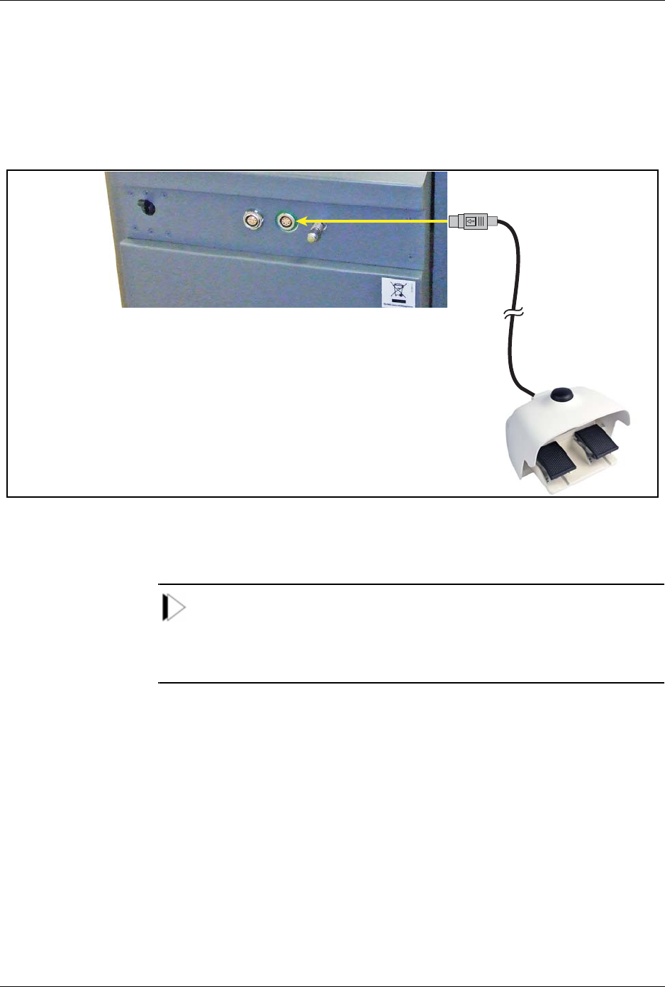
Connecting the Footswitch
Insert the footswitch connector into the footswitch receptacle on the rear
of the laser system console. Align the red dot on the footswitch connector
on top, then press it in.
Figure 4: Connecting the Dual-Pedal Footswitch
NOTE:
If the footswitch is not properly connected when the laser system is turned
on, the message Attach Footswitch appears in the notification bar until
the footswitch is properly connected.
Lumenis® PulseTM 50H / 100H Laser Systems Connecting the External Door Interlock
UM-20006520DE, Rev. A Page 36
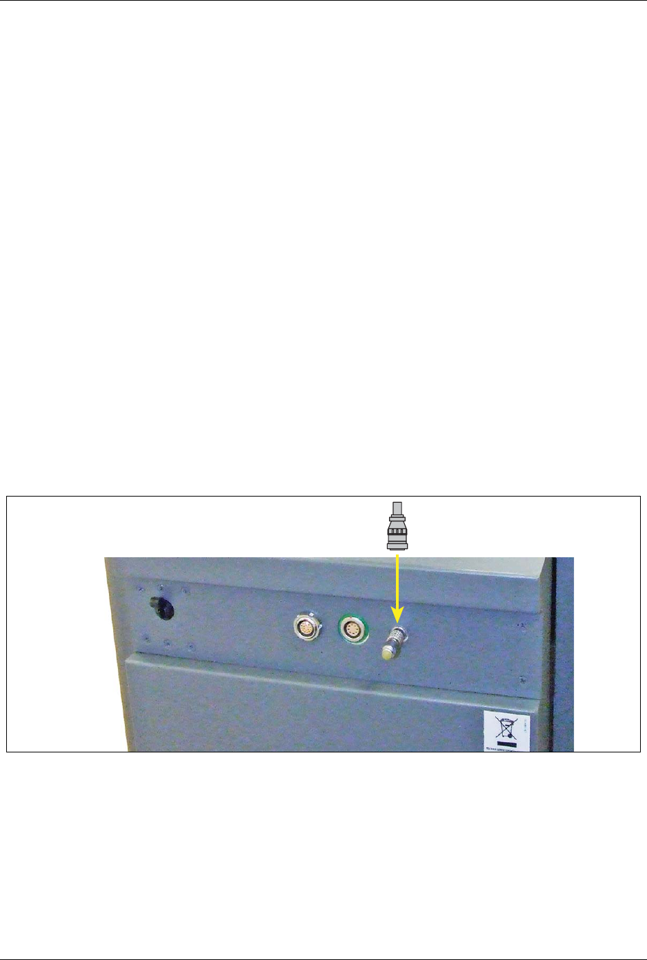
Connecting the External Door Interlock Connector
The external door interlock is a safety feature that disables the laser
system if the treatment room doors are opened or the external door
interlock connector is removed while the laser system is in Ready mode.
The laser system remains inoperative until the connector is inserted.
1. Align the pins of the external door interlock connector with the socket
of the external interlock receptacle.
2. Insert the external interlock connector into the external interlock
receptacle.
3. Turn the metal lock clockwise until it screws in.
4. If the treatment door is opened or if the external door interlock
connector is removed, the laser system automatically disables and
returns to Standby mode and a notification appears in the notification
bar.
5. To resume treatment, close the treatment room door or reinsert the
external door interlock connector, and press the Ready button.
Figure 5: Connect the External Door Interlock Connector
Lumenis® PulseTM 50H / 100H Laser Systems Plugging in the Main Power Cable
UM-20006520DE, Rev. A Page 37
Plugging in the Main Power Cable
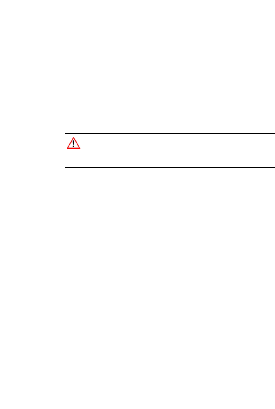
1. Turn off the main electrical service (wall circuit breaker).
2. Ensure that the laser system’s main power circuit breaker is in the off
(down) position.
3. Insert the laser system’s main power plug into the wall socket. If the
laser system has a locking plug and socket, connect the plug collar to
the socket so that the plug is secure from loosening.
4. Turn on the main electrical service (wall circuit breaker).
WARNING:
To avoid risk of electric shock, this equipment must only be connected to
a supply mains with protective earth.
Lumenis® PulseTM 50H / 100H Laser Systems Connecting the Optical Fiber
UM-20006520DE, Rev. A Page 38
Figure 6: Main On/Off switch and Main Power Plug
Connecting the Optical Fiber
Before connecting the optical fiber to the laser system, refer to the
appropriate optical fiber instruction guide for specific instructions, such as
optical fiber inspection, sterilization, and assembly.
WARNING:
• Carefully inspect the optical fiber sterile packaging to ensure that it
has not been torn or punctured. If there is any damage to the sterile
packaging, do not use the optical fiber.
• When using an optical fiber, always inspect the optical fiber to ensure
that it has not been kinked, punctured, fractured, or otherwise
damaged. The optical fiber may be damaged if stepped on, pulled, left
lying in a vulnerable position, kinked, or tightly coiled. Do not clamp
the cable with a hemostat or other instruments. If sterile tape is used,
always remove the tape before lifting the cable. A damaged optical
Main Power Plug
Main Power
Circuit Breaker
Lumenis® PulseTM 50H / 100H Laser Systems Connecting the Optical Fiber
UM-20006520DE, Rev. A Page 39
fiber may cause accidental laser exposure or injury to the treatment
room personnel or patient, and/or fire in the treatment room.
• To avoid possible damage to the optical system, use only qualified
Lumenis delivery systems. Using other than Lumenis delivery systems
may jeopardize safe operation or damage the laser system and will
void your Lumenis warranty or service contract.
• To prevent accidental laser discharge, always turn off the laser system
before connecting the optical fiber.
• Always check the expiration date on the optical fiber packaging; do
not use a optical fiber whose expiration date has passed.
NOTE:
SIS (Secure Identification System) enabled Lumenis Pulse 50H and
Lumenis Pulse 100H laser systems will only operate with Lumenis-
qualified SIS optical fibers. Attaching any other type of fiber will disable
laser emission.
To ensure sterility of the optical fiber, the following aseptic technique
must be used when you connect the optical fiber to the laser system:
1. Inspect the optical fiber as instructed in the appropriate optical fiber
instruction guide.
WARNING:
Never inspect the optical fiber while it is connected to the laser
system. Accidental laser exposure can cause severe eye damage.
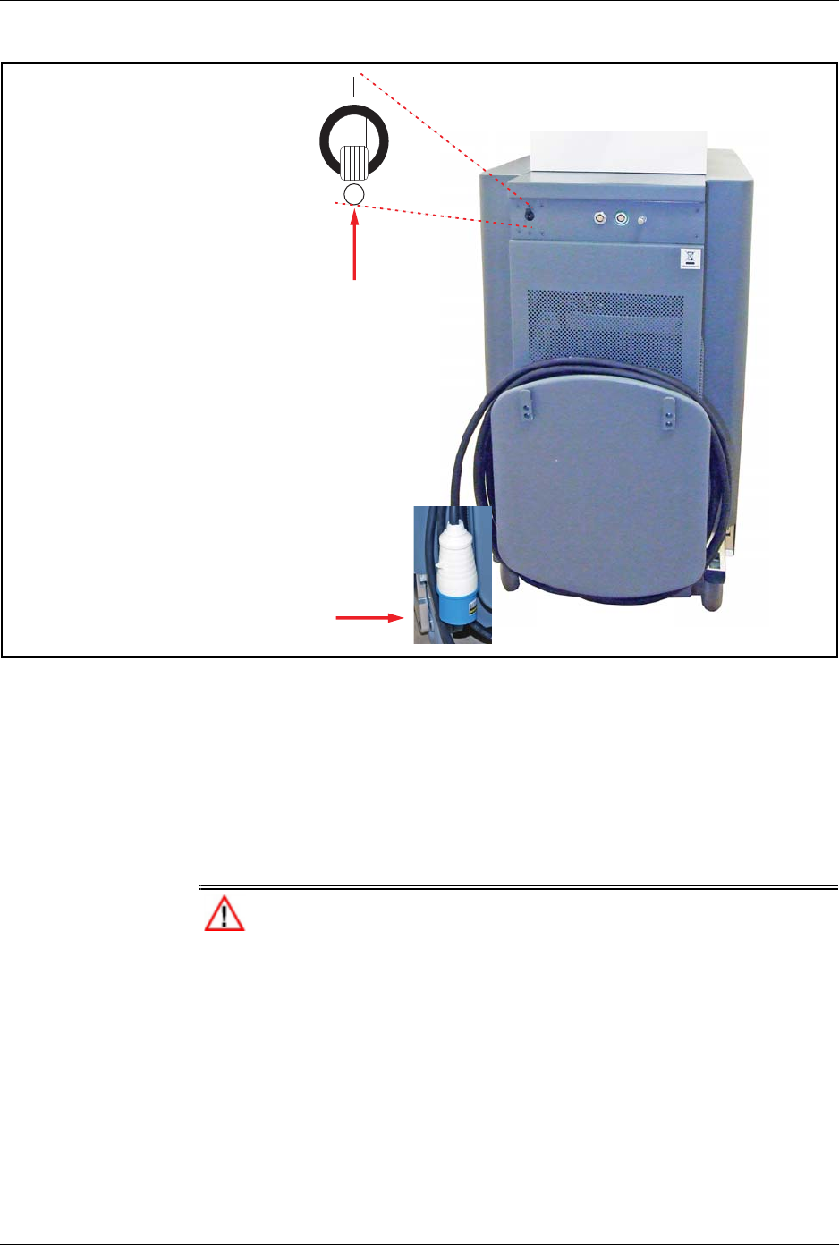
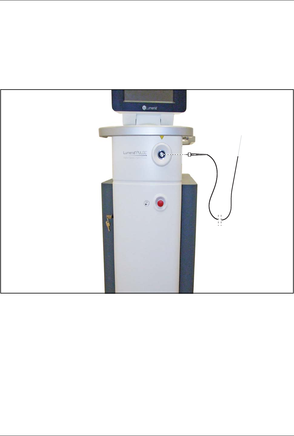
2. The scrub nurse hands off the laser connector to the circulating nurse.
3. The circulating nurse removes the protective cap from the laser
connector.
Lumenis® PulseTM 50H / 100H Laser Systems Connecting the Optical Fiber
UM-20006520DE, Rev. A Page 40
4. The circulating nurse secures the laser connector to the laser system by
screwing the connector into the optical fiber receptacle on the front of
the laser system.
If the laser connector is not properly seated and securely screwed into
the optical fiber connection port, the attach fiber message appears in
the notification area on the control screen.
Figure 7: Connecting the Optical Fiber
R
R

Lumenis® PulseTM 50H / 100H Laser Systems SIS (Secured Identification System) Tech-
UM-20006520DE, Rev. A Page 41
WARNING:
When removing the protective cap, hold the laser connector, not the strain
relief or optical fiber. Pulling on the strain relief or optical fiber may
damage the optical fiber and result in unintended laser exposure.
CAUTION:
Do not remove the protective cap from the laser connector in the sterile
field. Removing the protective cap in the sterile field may compromise
sterility.
SIS (Secured Identification System) Technology
SIS enabled Lumenis Pulse 50H and Lumenis Pulse 100H laser systems
will only operate with Lumenis-qualified SIS (Secure Identification
System) optical fibers. Attaching any other type of fiber will disable laser
emission.

Lumenis® PulseTM 50H / 100H Laser Systems Chapter 6: Operating Instructions
UM-20006520DE, Rev. A Page 42
Chapter 6: Operating Instructions
Emergency Stop Switch
In an emergency, press the laser emergency stop switch on the system’s
front panel, to immediately disable emission of the laser energy (Refer to
figure 8.).
NOTE:
When the main power cable is connected to the electrical source, some
internal circuits remain energized. To de-energize all internal circuits, set
the laser system's main circuit breaker - located on the rear panel - to the
Off position, and turn off the main electrical service (wall circuit breaker).
Figure 8: Controls for Turning Off the Laser System
Emergency Stop
Switch
Keyswitch

Lumenis® PulseTM 50H / 100H Laser Systems Safety Eyewear
UM-20006520DE, Rev. A Page 43
Safety Eyewear
Verify that all persons in the operating room are equipped with
appropriate laser safety eyewear.
Verification of Connections
1. Verify that the footswitch is properly connected.
2. Verify that the remote interlock connector is connected.
Powering on the System
1. Set the laser system’s main power circuit breaker to the On (up)
position.
2. Insert the key into the keyswitch (Refer to figure 8.) and rotate the key
to the || (start) position; hold for one full second and release the key.
Upon release, the spring-loaded key rotates to the |(on) position.
A laser self-test and warm-up begin. The self-test and warm-up take
approximately one minute. As internal tests are performed, self-test
pass/fail messages display on the control screen. When the self-test is
successfully completed, the main Treatment screen displays on the
control panel.
NOTE:
If any fault conditions are encountered during laser system start-up and
self-test, error messages can appear in the notification area on the control
screen. Refer to the Troubleshooting section later in this manual.
Restarting the Laser System
If it becomes necessary to restart the system:
1. Turn the keyswitch to the (off) position.
2. Wait 5 seconds, then rotate the keyswitch to the || (start) position; hold
for one full second, and release the key.

Lumenis® PulseTM 50H / 100H Laser Systems Treatment Screen Description
UM-20006520DE, Rev. A Page 44
Treatment Screen Description
Once the laser self-test and warm-up have successfully completed, the
main Treatment screen displays on the control panel.
The elements of the Treatment screen are detailed as follows (the
numbered arrows in figure 9 correlate to the numbered steps below):
1. Left Pedal Designation – displays which footswitch pedal should be
used for the group of output parameters in the box beneath the
designator.
2. Right Pedal Designation – displays which footswitch pedal should be
used for the group of output parameters in the box beneath the
designator.
3. Treatment Settings for each pedal – each side of the screen defines
the Energy, Frequency and Pulse width settings for lasing when the
corresponding pedal is pressed. Press the ► or ◄ selectors to reach
the desire settings; the derived power will be displayed
4. Pulse Width – the user may set the laser emission mode to short or
long pulses. Toggle this button to select Long or Short pulses.
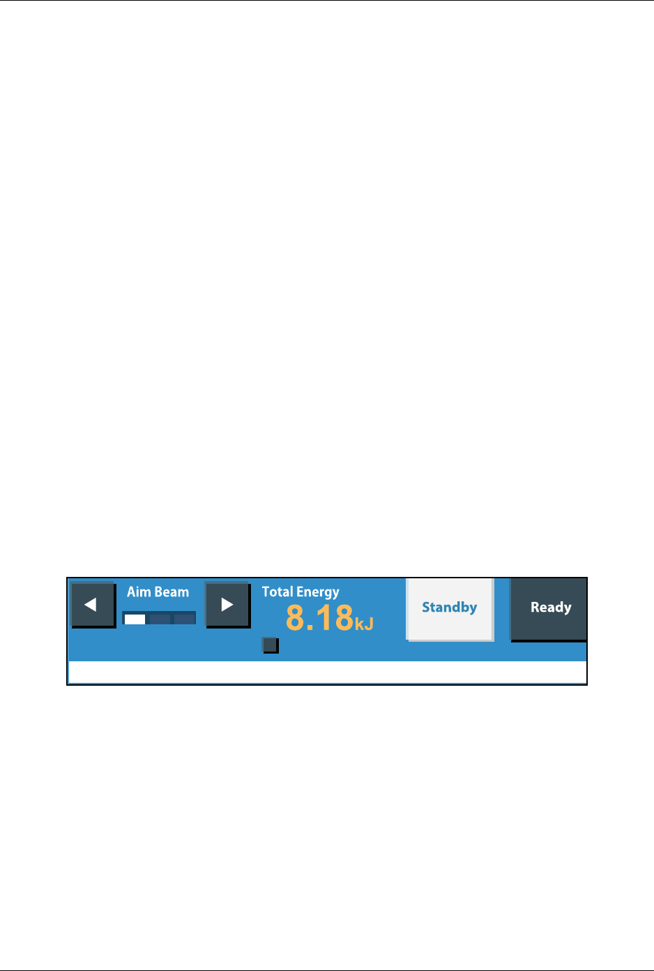
5. Aiming Beam – the Aim Beam display shows the selected aiming
beam intensity: high, medium, low or off.
• At laser system turn on the aiming beam setting retains the intensity
setting from the last use of the laser system, or it will automatically
select the minimum setting it the aiming beam was turned off at the
last shut-down.
•Press the Aim Beam ► or ◄ selectors to set the aiming beam
intensity.
• To turn off the aiming beam, press the ◄ selector until no bars are
illuminated.
CAUTION:
If the aiming beam is turned off, ensure that the tip of the optical fiber and
the targeted surgical site are both under direct visualization.

Lumenis® PulseTM 50H / 100H Laser Systems Treatment Screen Description
UM-20006520DE, Rev. A Page 45
Figure 9: Treatment Beam Delivery via Right or Left Pedals
6. Notification bar - errors and notifications appear in the notification
bar at the bottom of the screen, to alert you of a necessary action or a
laser malfunction. Refer to Handling Error Messages and
Notifications for a list of advisory indications, their probable causes,
and solutions.
7. Total Energy – The Total Energy display shows the total holmium
energy, in kilojoules, delivered since the last reset. The display
automatically resets to zero the first time you press Ready after
turning on the laser system, to allow reading of the total Energy of last
treatment. To manually reset the display, press the Clear kJ selector.
8. Standby/Ready mode selection – Standby/Ready buttons determine
whether pressing the footswitch will activate the laser system (Ready
mode) or not (Standby mode).
WARNING:
Except during actual treatment, the laser system must always be in
Standby mode. Maintaining the laser system in Standby mode prevents
accidental laser exposure if the footswitch is inadvertently pressed.
9. Clear kJ – clears the calculated total energy from the control panel;
should always be cleared at the beginning of a new procedure.
Fault XXX
Clear kJ
5
3
1
897
6
2
4
4

Lumenis® PulseTM 50H / 100H Laser Systems Laser Emission Indicators
UM-20006520DE, Rev. A Page 46
Laser Emission Indicators
• The Energy, Frequency and Pulse Width parameter areas are
highlighted by a yellow margin surrounding the applicable pedal on
the screen (see figure 10) when the appropriate pedal is pressed, to
alert the operator that laser energy is being emitted.
• An audible signal sounds during laser energy emission. The audible
signal is different for the right and left pedals.
Figure 10: Laser Emission Indicator

Lumenis® PulseTM 50H / 100H Laser Systems Intra-Operative Instructions
UM-20006520DE, Rev. A Page 47
Intra-Operative Instructions
1. Set the aiming beam to high intensity.
2. Test the integrity of the aiming beam.
Hold a non-reflective surface, such as a tongue depressor, in front of
the optical fiber tip. For side-emission delivery systems, hold the non-
reflective surface in front of the side opening at the fiber tip.
A green spot, the aiming beam, should appear on the surface. If the
aiming beam is weak, check that it is set to high intensity. If the aiming
beam is still weak, verify that the laser debris shield and optical fiber’s
connector are not damaged. Refer to Inspect the Debris Shield and the
section in the appropriate optical fiber instruction guide (look under
“Inspect the laser connector”).
WARNING:
• Do not use the optical fiber if the aiming beam is set to high intensity
and is still weak or not visible; the optical fiber may be damaged. A
damaged optical fiber may cause accidental laser exposure or injury to
the treatment room personnel or patient, and/or fire in the treatment
room.
• Do not use the laser system or optical fiber if the aiming beam has not
been verified. Verifying the aiming beam integrity is extremely
important for the safe operation of your laser equipment.
• Do not use the laser system or optical fiber if the aiming beam is not
visible. Operating the laser system without the aiming beam may
result in laser exposure to non-target tissue and possible injury.
NOTE:
When using the optical fiber with an endoscopic camera, lower the
intensity of the camera light if the aiming beam is weak or not visible.
Doing so will not affect visibility at the treatment site, since the camera
compensates for the lower level of light.
3. Enter the desired parameters into the Energy, Frequency and Pulse
Width selectors on the control panel.
4. Position the aiming beam on the target tissue.
Lumenis® PulseTM 50H / 100H Laser Systems Intra-Operative Instructions
UM-20006520DE, Rev. A Page 48
5. Press the Ready button to switch to Ready mode.
WARNING:
Always check your parameter settings on the screen before setting the
system to Ready mode.
6. Verify that your foot is on the appropriate footswitch pedal for the left-
side or right-side parameter settings on the screen.
7. Press the footswitch that corresponds to the desired set of parameters
to deliver the treatment beam.
As the laser delivers the treatment beam, the highlighted yellow
margin appears around the appropriate footswitch settings area on the
control screen and an audible signal sounds to alert you that laser
energy is being emitted. The audible signal is different for the right
and left pedals.
8. Press the Ready and Standby buttons on the screen or use the
footpedal Ready/Standby button (on the top of the footswitch) to
toggle between Ready and Standby modes.
9. If surgery is interrupted, set the laser system to Standby mode to
disable the footswitch.
WARNING:
Always set the laser system to Standby mode when it is not in use to
avoid unintended laser emission.
Lumenis® PulseTM 50H / 100H Laser Systems Post-Operative Instructions
UM-20006520DE, Rev. A Page 49
Post-Operative Instructions
1. Set the system to Standby mode.
2. Turn the keyswitch to the (off) position.
3. Disconnect the optical fiber from the laser system.
If the optical fiber is single-use, discard it. If it is multiple-use, prepare
the optical fiber for reuse as instructed in the appropriate optical fiber
instruction guide.
4. Set the laser system’s main power circuit breaker to the Off (down)
position
5. Turn off the mains circuit breaker.
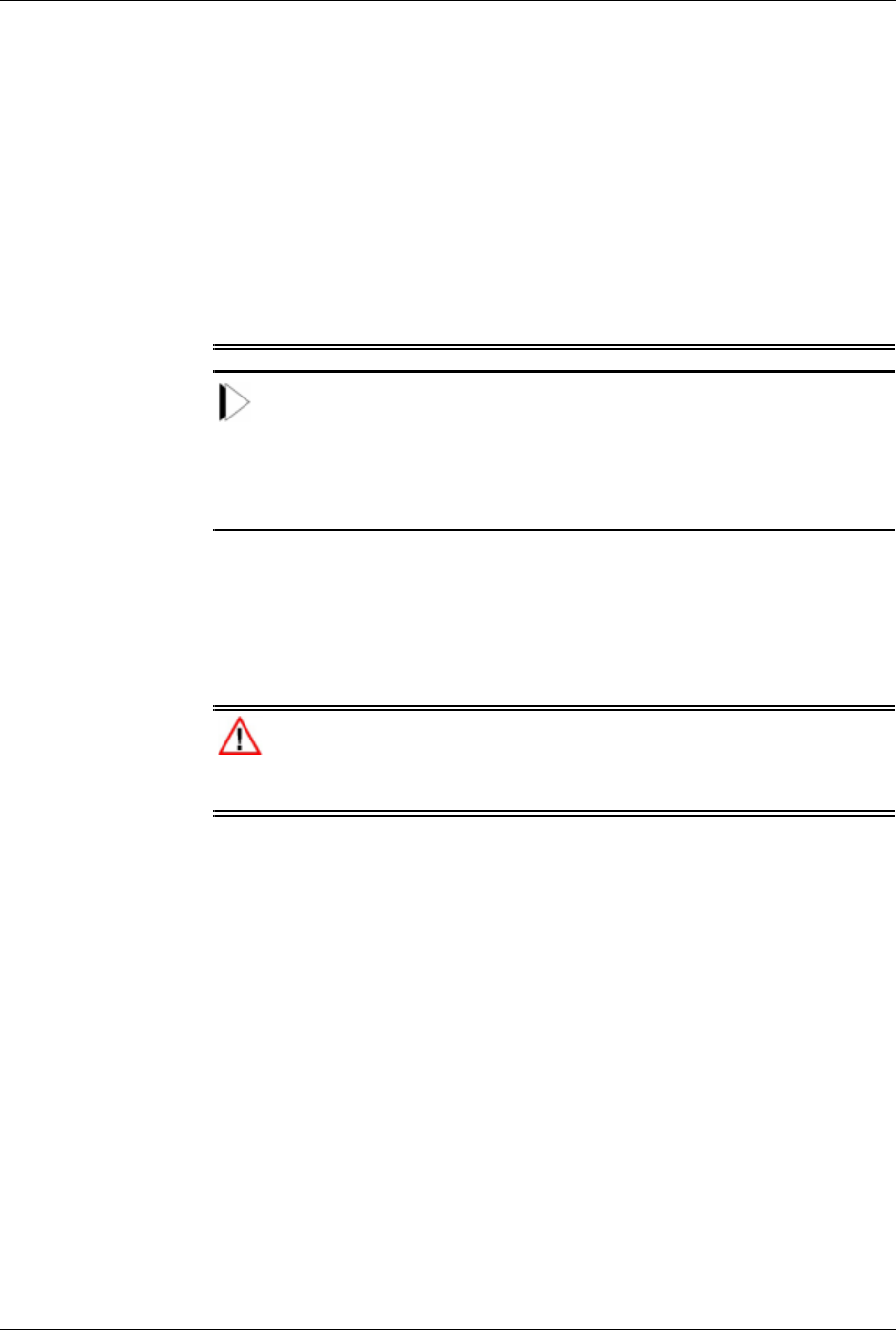
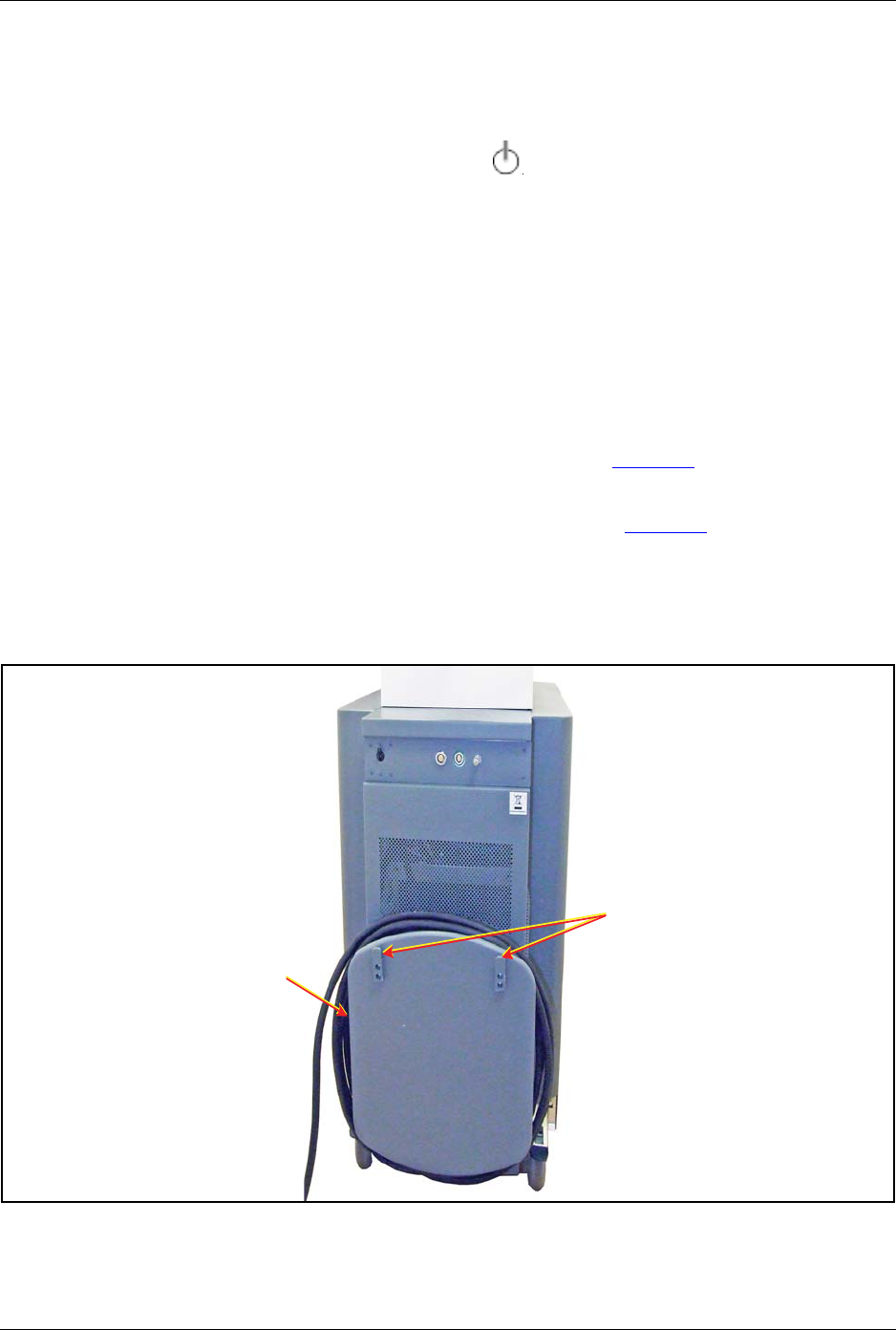
6. Remove the main power plug from the wall receptacle and wrap the
power cable around the cable rack (see figure 11).
7. Remove the footswitch connector from the laser system. and hang it
from the footswitch storage mounts (see figure 11).
8. Disconnect the external door interlock.
9. Clean the exterior surfaces of the laser system.
Figure 11: Laser Console Cable Rack and Footswitch Storage Mounts
Footswitch Storage
Mounts
Cable Rack

Lumenis® PulseTM 50H / 100H Laser Systems Moving the Laser Console
UM-20006520DE, Rev. A Page 50
Moving the Laser Console
Using the laser console’s front and rear handles, move the laser system to
the desired site.
CAUTION:
• As with any heavy equipment, use caution when tilting the laser
console or moving it up or down an incline. For optimum safety, use a
second person when moving up or down a steep incline.
• Do not move the laser console rapidly over uneven surfaces; doing so
may damage the equipment.
Lumenis® PulseTM 50H / 100H Laser Systems Chapter 7 - Troubleshooting and Mainte-
UM-20006520DE, Rev. A Page 51
Chapter 7 - Troubleshooting and
Maintenance
Handling Error Messages and Notifications
Notifications and error messages appear in the Notification bar at the
bottom of the screen.
1. Follow the instructions in the notification bar if any are given.
2. If instructions appear, perform the required task as detailed in the
message. If the error is resolved, the message will fade and normal
operation may be resumed.
3. Several types of errors will not fade - in a case like this press the
Standby button to clear the notifications or error message; normal
operation may be resumed.
4.
Several types of errors will only appear with a number (“
Fault XXX
”);
press the Standby button to clear the error and try to resume normal
operation. If this does not resolve the problem restart the system.
5. If the problem does not resolve, contact Lumenis Customer Service.
Figure 12: Notification Bar
Fault XXX
Clear kJ

Lumenis® PulseTM 50H / 100H Laser Systems Troubleshooting
UM-20006520DE, Rev. A Page 52
Troubleshooting
If the system fails to operate properly, this troubleshooting guide will help
you to locate and correct the malfunction.
Initialization Error Message Appears
1. Write down the error number.
2. Restart the system via the keyswitch.
3. If the problem re-occurs, contact Lumenis Customer Service.
System Does Not Turn On
The control screen does not illuminate.
1. Plug in the laser system.
2. Set the laser system's main circuit breaker to the On (up) position.
3. Turn on the main electrical circuit breaker.
4. Use another power outlet, or have the outlet professionally tested and
repaired, if necessary.
Inadequate or No Aiming Beam
1. Adjust the aiming beam intensity.
2. Replace the optical fiber.
3. Lower the intensity of the endoscopic camera light.
4. Inspect and, if necessary, replace the debris shield.
5. Contact Lumenis Customer Service.
No Laser Energy Emission
1. Replace the optical fiber.
2. Inspect and, if necessary, replace the debris shield.
3. Contact Lumenis Customer Service.

Lumenis® PulseTM 50H / 100H Laser Systems “Popping” or “Tapping” Coming Sound
UM-20006520DE, Rev. A Page 53
“Popping” or “Tapping” Coming Sound from the Fiber Port
This is probably due to a malfunction of the optical fiber connector.
• Replace both the optical fiber and the debris shield.
Fiber Burn Back
Optical fiber burn back may occur during prolonged procedures,
especially when using higher power.
• Renew the optical fiber tip by stripping and cleaving the fiber.
Unrecognized Fiber
1. Replace the optical fiber with a Lumenis compatible one and resume
normal operation.
2. If problem persists, contact Lumenis Service.
A Notification or Error Message Appears on the Control Panel
There are three types of clearable errors:
• An error message that clears automatically (i.e., “Attach an
Authorized Fiber”) when an authorized fiber is attached.
• An error message that clears when the stated problem is resolved
(i.e., “High temperature” will clear when the temperature of the
system goes down).
• An error that requires user acknowledgement after resolving the
problem (i.e., “Energy High”); press the Standby button on the
screen to clear the message.

Lumenis® PulseTM 50H / 100H Laser Systems System Overheats
UM-20006520DE, Rev. A Page 54
System Overheats
The laser system may overheat if it is used at a high power for an
extended amount of time.
• Verify that the treatment room temperature is between 10 and 30°C
(50 and 86°F).
• Verify that the laser system is at least 50 centimeters (20 inches)
from walls, furniture, or other equipment.
NOTE:
If the laser system overheats, do not turn it off. Leaving the laser system
on allows the internal cooling system to quickly cool the system’s internal
components. Allow the system to cool for several minutes and resume
normal operation.
Message Appears: Attach an Authorized Fiber
SIS enabled Lumenis Pulse 50H and Lumenis Pulse 100H laser systems
will only operate with Lumenis-qualified SIS (Secure Identification
System) optical fibers. Attaching any other type of fiber will disable laser
emission.
• Attach an authorized fiber or Contact Lumenis Customer Service to
obtain the correct fibers.
• Refer to the optical fiber’s Directions for Use document for specific
instructions on how to work with the fiber.
Message Appears: Attach fiber
The optical fiber’s connector is not properly connected to the laser
system.
• Connect the optical fiber as instructed earlier in this manual.
Message Appears: Attach footswitch
The footswitch is not properly connected to the laser system.
• Connect the footswitch as instructed earlier in this manual.

Lumenis® PulseTM 50H / 100H Laser Systems Message Appears: Check footswitch
UM-20006520DE, Rev. A Page 55
Message Appears: Check footswitch
You are pressing either one both footswitch pedals in Standby mode.
• Release the footswitch, switch to Ready and press one of the
footswitch pedals.
Message Appears: Check interlock
The interlock door is open, or the interlock plug is not properly inserted.
• Close the interlock door, or insert the interlock plug.
Message Appears: Insert debris shield
The debris shield is missing or is not properly inserted.
• Insert the debris shield.
Message Appears: No lasers
The system is experiencing a laser malfunction.
• Contact Lumenis Customer Service.
Message Appears: Energy high
The energy delivered is more than 50% higher than the selected level.
•Press the Standby button to clear the message, then press the Ready
button and resume normal operation. If the condition continues, turn
off the laser system for five seconds, then turn it back on. If the
condition persists, contact Lumenis Customer Service.
Message Appears: Energy low
The energy delivered is less than 50% of the selected level.
•Press the Standby button to clear the message, then press the Ready
button and resume normal operation. If the condition continues, turn
off the laser system for five seconds, then turn it back on. If the
condition persists, contact Lumenis Customer Service.

Lumenis® PulseTM 50H / 100H Laser Systems Message Appears: Rate high
UM-20006520DE, Rev. A Page 56
Message Appears: Rate high
The pulse rate delivered is at least 20% more than the selected level.
•Press the Standby button to clear the message, then press the Ready
button and resume normal operation. If the condition continues, turn
off the laser system for five seconds, then turn it back on. If the
condition persists, contact your Lumenis Customer Service.
Message Appears: Rate low
The pulse rate delivered is less than 80% of the selected level.
•Press the Ready button to clear the message. If the condition
continues, turn off the laser system for five seconds, then turn it
back on. If the condition persists, contact Lumenis Customer
Service.

Lumenis® PulseTM 50H / 100H Laser Systems Routine Periodic Maintenance
UM-20006520DE, Rev. A Page 57
Routine Periodic Maintenance
Regular cleaning, inspection, testing, and repair are the basis of any
effective preventive maintenance program. Such a program helps keep the
system in top working order and ensures the reliability of safety interlocks
and fail-safe mechanisms.
A recommended routine inspection and maintenance schedule is provided
below.
Inspection/Service Frequency Performed By Remarks
Routine exterior
cleaning. As required by hospital/
clinic protocol. Hospital/Clinic
Staff None
Inspect cables and all
external surfaces for
damage. Weekly Hospital/Clinic
Staff If damage is found, call Lumenis
Customer Service.
Inspect electrical
connections. Weekly Hospital/Clinic
Staff If damage is found, call Lumenis
Customer Service.
Check remote interlock
connection and
emergency stop button. Weekly Hospital/Clinic
Staff
If interlock and/or button do not
perform as required, call
Lumenis Customer Service.
Inspect/replace the
debris shield Weekly or if required due
to low output energy. Hospital/Clinic
Staff
If output energy is still low after
replacing the shield, call
Lumenis Customer Service.
Deionizer and particle
filters replacement. Annually Lumenis
Service
Must be performed only by
Lumenis-authorized technical
personnel.
Electrical safety checks. Annually (or as required
by institutional
procedures).
Lumenis
Service
Must be performed only by
Lumenis-authorized technical
personnel.
Check and perform
energy detectors
calibration procedure.
Annually, or as required if
system does not perform
to specifications, or
occurrence of error
messages.
Lumenis
Service
Must be performed only by
Lumenis-authorized technical
personnel.

Lumenis® PulseTM 50H / 100H Laser Systems Hospital/Clinic Staff Maintenance
UM-20006520DE, Rev. A Page 58
Hospital/Clinic Staff Maintenance
Visual Inspection
The exterior of the system should be inspected once a week to ensure that
there are no loose cable connections and that there is no damage to the
system.
Routine Exterior Cleaning
The external surfaces of the system (console, LCD panel) and the
footswitch should be cleaned when the system is received, and thereafter
as required by clinic protocol.
The outer surfaces of the system may be wiped clean with a soft, lint-free
cloth dipped in 70% isopropyl alcohol, or a hospital-grade disinfectant
solution.
CAUTION:
Do not spray or pour cleaning agents directly on the laser console or
control screen. You may damage the console, screen and laser system
electronics.
Remote Interlock Check
Laser beam emission is disabled when the remote interlock plug is not
connected or the connected door is not closed. To check this:
1. Set the system to Ready mode.
2. Unplug the remote interlock connector plug; the system should display
the following message in the notification bar: Check Interlock. re-
insert the interlock connector plug.
3. Open the connected door; the system should display the following
message in the notification bar: Check Interlock.
4. If the system does not display the message and remains in Ready
mode, discontinue use and contact Lumenis Service.

Lumenis® PulseTM 50H / 100H Laser Systems Emergency Stop Button Check
UM-20006520DE, Rev. A Page 59
Emergency Stop Button Check
The Emergency Stop Button is designed to disable the laser system
when pressed. To check this interlock:
1. With the system On, press down on the emergency stop button; the
system will turn itself off.
2. Restart the laser system by turning the keyswitch.
3. Press the Ready button on the LCD or footswitch to enable lasing.
If this is not the situation, discontinue use and contact Lumenis Service.
Inspect the Debris Shield
The debris shield protects the internal optical components of the laser
system from damage by a faulty or misused optical fiber.
Remove the Debris Shield
1. Turn off the laser system.
2. Locate the debris shield panel covering on the upper right-hand side of
the laser console.
3. Remove the panel covering with your fingers.
Figure 13: Locate the debris shield
Debris shield panel cover
on side of console

Lumenis® PulseTM 50H / 100H Laser Systems Inspect the Debris Shield
UM-20006520DE, Rev. A Page 60
4. Grasp the debris shield handle, and pull the shield out of the
receptacle.
Figure 14: Remove the debris shield
Inspect the Optic
Inspect the debris shield optic to verify that it is free of any burn marks,
scratches, dust, or fingerprints. If the optic is damaged or dirty, replace it
as instructed in Change the Debris Shield Optic in this section. If the optic
is free of damage, reinsert the debris shield into the receptacle as
instructed below.
Figure 15: Inspect the Debris Shield Optic
Debris shield handle
Optic

Lumenis® PulseTM 50H / 100H Laser Systems Inspect the Debris Shield
UM-20006520DE, Rev. A Page 61
Reinsert the Debris Shield
1. Holding the debris shield handle, position the shield so that the pin is
aligned with the pin groove.
2. Insert the debris shield into the debris shield receptacle.
3. Replace the panel covering.
4. Restart the laser system.
Figure 16: Reinsert the Debris Shield
Pin Groove
Pin
Handle

Lumenis® PulseTM 50H / 100H Laser Systems Change the Debris Shield Optic
UM-20006520DE, Rev. A Page 62
Change the Debris Shield Optic
1. Use snap ring pliers to remove the snap ring that secures the debris
shield optic to the body of the shield.
2. Carefully turn over the debris shield holder, and allow the debris
shield optic and spring washer to drop onto a lens cleaning tissue.
3. Open the vial containing the new debris shield optic.
CAUTION:
To avoid contamination, do not touch the surface of the debris shield optic
with your fingers.
4. Carefully turn over the vial, and allow the optic to drop onto a lens
cleaning tissue.
5. Lay the debris shield over the new debris shield optic.
6. Hold the lens cleaning tissue over the debris shield optic opening, and
slowly turn over the debris shield until the optic is facing up.
7. Place the spring washer over the debris shield optic.
8. Hold the debris shield optic and spring washer in place with the lens
cleaning tissue, and use snap ring pliers to insert the snap ring over the
spring washer. Ensure that the snap ring is in place and secure before
releasing the snap ring pliers.
Figure 17: Change the Debris Shield Optic

Lumenis® PulseTM 50H / 100H Laser Systems Professional Maintenance
UM-20006520DE, Rev. A Page 63
Professional Maintenance
This section covers checks, calibrations and maintenance that require
internal access to the laser system’s console and special skills.
CAUTION:
The Lumenis Pulse 50H or 100H laser system may only be serviced by
Lumenis certified field service engineer using an approved service
manual.
WARNING:
These procedures assume specific knowledge, training and use of tools
not available to repair personnel outside of Lumenis. Since performing
these procedures may expose the user to potential electrical and laser
energy hazards, Lumenis requires that these procedures only be
performed by trained service personnel.
Energy Detectors Calibration
Energy detectors check and calibration must be performed by an engineer
or technician qualified to work with laser equipment. Questions regarding
this procedure should be referred to Lumenis Customer Service.
DISCLAIMER:
Calibration is a service procedure to be done only by Lumenis-certified
service engineers or customers who have taken and passed a Lumenis
Service Certification Training course. Adjustment by anyone other than a
trained Lumenis service engineer or a certified customer voids any
existing manufacturer’s warranty on the instrument. A service manual for
the laser system may be purchased from Lumenis. It is company policy
not to distribute service tools outside of the Lumenis service organization.
Possession of service instructions or tools does not authorize repair or
modification of a Lumenis instrument by uncertified personnel.
The Lumenis Pulse 50H or 100H system incorporates internal energy
detectors which are used to control lasing energy. The energy detectors
check compares the internal energy reading to the reading from a
calibrated external power meter

Lumenis® PulseTM 50H / 100H Laser Systems Energy Detectors Calibration
UM-20006520DE, Rev. A Page 64
WARNING:
All personnel in the immediate area must wear eye protection rated
specifically for the Holmium laser system.
NOTE:
Optical components must be clean before the energy detectors check is
performed.
1. Verify that all personnel are wearing appropriate laser safety eyewear.
2. Position a calibrated, external power meter 15 cm (6 inches) from the
output end of the optical fiber.
3. Turn on the laser system as instructed earlier in this manual.
4. Set the laser system to deliver 5 Watts of laser energy.
5. Target the aiming beam at the detector disc of the external power
meter.
6. Set the laser system to Ready mode.
7. Press the footswitch to deliver the laser energy into the detector disc of
the external power meter. Maintain delivery of the laser energy for
20 seconds.
8. Release the footswitch and record the external power meter's reading.
9. If the external power meter reading falls above or below ±20% of the
requested energy on your laser system, discontinue this procedure and
contact Lumenis Customer Service.

Lumenis® PulseTM 50H / 100H Laser Systems Chapter 8: System Requirements and
UM-20006520DE, Rev. A Page 65
Chapter 8: System
Requirements and General
Information
Installation
The laser system is shipped directly from the factory to your site. Your
Lumenis service representative initially uncrates, inspects, sets up, and
installs the laser system to ensure that it is working properly. In addition,
Lumenis provides in-service training to ensure that your surgical staff is
experienced with the performance and safety considerations of the laser
system.
Thereafter, you or the nursing staff at your facility will perform the daily
maintenance routines associated with the laser system and any delivery
systems used during surgery.
If your scheduled surgical procedure requires disposable delivery devices
or accessories, it is helpful to have extra items ready and available in the
treatment room should they be needed to complete a procedure.
CAUTION:
For Canada, the system must be installed and operated according to CAN/
CSA-Z386-08: Laser safety in health care facilities.
Accessories
• Safety eyewear
• SlimLine SIS 200, 365, 550, 1000
• SlimLine EZ SIS 200, 365, 550
• Xpeeda D/S/L optical fiber
• SlimLine Endo SIS 200, 365, 550 optical fibers
• SlimLine GI SIS 365 optical fiber

Lumenis® PulseTM 50H / 100H Laser Systems Tools (Optional)
UM-20006520DE, Rev. A Page 66
Tools (Optional)
• Scissors
• Optical fiber stripper
• Cleaving tool
• Optical fiber inspection scope
• SlimLine steam sterilization tray
Electrical Requirements
Refer to the System Specifications section in this manual.
Electrical Utilities
Lumenis Pulse 50H or 100H laser systems are available in several
electrical configurations. Electrical power should be setup according to
the model ordered. The line wires in the power cable shall be connected to
the building power, and the green/yellow wire must be connected to the
building ground.
The customer’s engineer or electrical contractor will be responsible for
ensuring that the proper electrical requirements are available at the site.
Systems Designed For Use Outside of Europe
For the 200-230 VAC configuration, supply the electrical power from a
dedicated 200, 208, or 230 VAC, single-phase, 50-60 Hz supply mains in
accordance with local codes. The socket and wall plug connection must be
rated for 30A @ 60 Hz or 30A @ 50 Hz and voltage of 200 ±10% VAC or
208 ±10% VAC or 230 ±10% VAC.
Systems Designed For Use in European Communities Under the MDD
To comply with the European Communities Medical Device Directive
93/ 42/EEC, and harmonized standards EN 60601-1 and EN 60601-2-22,
the 230 ±10%VAC configured laser must be either permanently connected
to a 32A, 230 ±10% VAC, single-phase, 50 Hz supply mains in Hard-
Wired Configurations UM-20006520EN, Rev. A Page 69 accordance with
national wiring regulations, or connected by means of a dedicated single-
phase, 32A, 230 ±10% VAC wall socket and lockable plug combination
designed to ensure the connection is “mechanically secured against
accidental loosening”. Such a connection will ensure compliance with
EN 60309 for this device. Wiring should be rated at 32A. Leakage current
for these lasers does not exceed 500 µA.
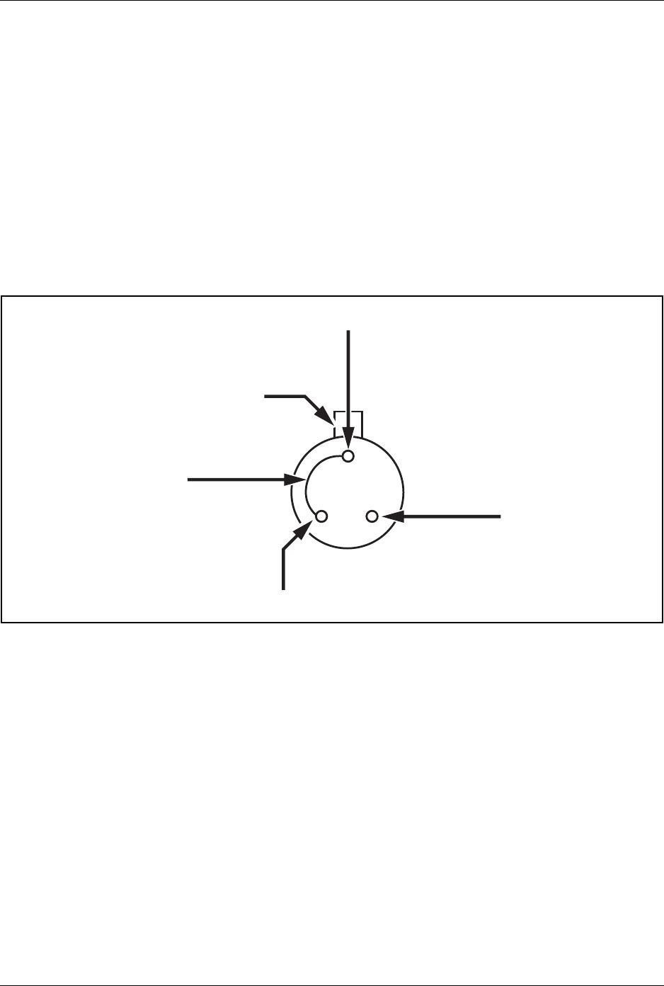
Lumenis® PulseTM 50H / 100H Laser Systems External Door Interlock Pin Assignments
UM-20006520DE, Rev. A Page 67
External Door Interlock Pin Assignments
The external door interlock is a safety feature that disables the laser
system if the treatment room doors are opened or the interlock plug is
removed while the laser system is in Ready mode.
The interlock can be set up with a remote switch, or an external switch can
be wired to the interlock plug. Plug wiring shall only be performed by a
qualified electrical professional. Total length of cable shall not exceed
five meters (16 feet).
Pin assignments are as follows:
Figure 18: External Door Interlock Pin Assignments (solder side of plug shown)
External Interlock
External Interlock RTN
Ground Shield
Locking tab with red dot
Jumper

Lumenis® PulseTM 50H / 100H Laser Systems Compliance With International Standards
UM-20006520DE, Rev. A Page 68
Compliance With International Standards
In compliance with international standards for laser medical equipment,
the system is equipped with the following:
Emergency Stop Button
The laser system has an emergency stop button knob that, when pushed,
immediately disables the laser system in emergency situations.
Keyswitch
Laser energy can be emitted only when the keyswitch is turned to the
Open position. The key can only be removed in the off position, and the
laser system only operates with the key in place. When treatment is
complete, always remove and secure the key to prevent unauthorized use
of the laser system.
WARNING:
Unauthorized use of this system may expose the operator/patient to poten-
tial electrical energy and laser radiation hazards.
Laser Emission Indicators
A laser emission indicator appears on the control screen to alert you that
laser energy is being emitted. During the treatment beam delivery, the
laser system emits an audible signal correlating to the pedal used.
External Door Interlock
An external door interlock outlet and plug are provided to disable the laser
system if the treatment room doors are opened while the laser system is in
Ready mode.
Protective Housing
The laser system has a protective housing that prevents unintended human
access to laser radiation. No sections of the protective housing can be
easily opened without special tools. This housing is to be opened only by
a Lumenis-certified technician.
Safety Shutter
The laser system features a safety shutter that prevents the treatment beam
from exiting the laser system. The safety shutter opens only when the
laser system is in Ready mode and the footswitch is pressed.

Lumenis® PulseTM 50H / 100H Laser Systems Manual Reset
UM-20006520DE, Rev. A Page 69
Manual Reset
If laser emission is interrupted during treatment (e.g., main electrical
power loss), the laser system automatically turns Off. To resume
treatment, you must manually restart the laser system using the main On/
Off button.
Electronic Fault Detection Circuitry
If any of the electronic system monitors detect a fault condition, laser
emission is disabled. The high voltage power supply disables, the safety
shutter closes, and the footswitch disables.
Safety Interlocks
The laser system has a safety interlock on the optical fiber laser connector.
Precision of Displayed Values
The precision of the energy and rate values displayed on the control
screen are factory preset to within ±5% of a calibrated standard. The
energy of every pulse is monitored by two internal detectors to ensure that
no safety hazard is caused by failure of a single component. If the
delivered system energy deviates from the commanded parameters by
more than 20%, you are notified and can continue lasing following
acknowledgment. Following 5 such occurrences in a single session this
becomes a fatal error and lasing cannot continue (laser system shuts
down).
Space Requirements
Position the laser console a minimum of 50 centimeters (20 inches) from
walls, furniture, or other equipment.

Lumenis® PulseTM 50H / 100H Laser Systems System Specifications
UM-20006520DE, Rev. A Page 70
System Specifications
Output parameters
Treatment laser beam
Laser type Holmium:YAG (Ho:YAG), pulsed
Laser wavelength 2.1 µm
Laser Classifications
FDA classification Class IV medical device
EN 60825 classification Class 4 laser
Power
Lumenis Pulse 50H: 1.0 to 50W
Lumenis Pulse 100H: 1.0 to 100W
Energy 0.2 - 3.5 Joules
Repetition rate
Lumenis Pulse 50H: 5 to 25 Hz
Lumenis Pulse 100H: 5 to 53 Hz
Pulse width 0.15 to 0.6 ms
Aiming beam
Laser Type Green DPSS, continuous wave
Laser wavelength 532 nm
Laser Classifications
FDA classification Class IIIa laser
EN 60825 classification Class 3R laser
Power 5 mW maximum
Input power recommended service
Vol t age 200/208/230 VAC ±10%
Frequency 50/60 Hz
Current • 30A @ 208/230 VAC @ 60 Hz
• 30A @ 200/208/230 VAC @ 50 Hz
Utility connection Single-phase grounded outlet
Cooling
Method Internal water-to-air heat exchanger
Cooling air Requirements Minimum 46 cm (18 in) from walls
Physical parameters
Size (W × D × H) cm (in.) 46 × 91 × 99 cm
(18 × 36 × 39 in.)
Weight 200 kg (441 lbs.)
Power cable length 7 m (23 ft.)
Footswitch cable length 5.2 m (17 ft.)
Environmental requirements (operating conditions)
Te m p e r a t u r e 10 – 30°C / 50– 86°F
Humidity 30 to 75% at 30°C/86°F

Lumenis® PulseTM 50H / 100H Laser Systems Laser Safety Eyewear
UM-20006520DE, Rev. A Page 71
Laser Safety Eyewear
Refer to Laser Safety Eyewear in the Safety and Regulatory section of this
manual for detailed laser safety eyewear information.
Replacement Parts Part Numbers
Compatible Optical Fibers
The laser system is intended for use only with Lumenis-qualified optical
fibers. Contact Lumenis Customer Service for a list of available products.
Pressure 77 – 106 kPa
Max. altitude 3,050 m (10,000 ft.)
Environmental requirements (non-operating conditions)
Te m p e r a t u r e 10 to 40°C (50 to 104°F)
Humidity 30 to 75% at 30°C/86°F
Debris shield (glass and holder) SPSA-10090190
Debris optic (glass only) SPOP-10025270
Laser system key 5107-0146

Lumenis® PulseTM 50H / 100H Laser Systems Decontamination of Returned Equipment
UM-20006520DE, Rev. A Page 72
Decontamination of Returned Equipment
In order to comply with postal and transportation laws, equipment shipped
to the supplier’s offices for return or repair must first be decontaminated.
To communicate that the returned equipment has been properly
decontaminated, a signed Decontamination Certificate (obtained from
Lumenis Customer Service) must be enclosed in the shipping package.
Failure to enclose the Decontamination Certificate will cause the supplier
to assume the product is contaminated. The supplier will assess the
customer with cleaning costs. Any decontamination inquiries should be
directed to Lumenis Customer Service.
Customer Service and Warranty
For specific and detailed warranty information for this instrument, please
refer to the first page of your purchase “Agreement” and the last page of
the “Terms and Conditions of Sale.”
Lumenis Center Address Telephone/Fax
Lumenis, Inc. 2033 Gateway Place, Suite 200
San Jose, CA 95110, USA Tel:+ 1.408.764.3000
Fax:+ 1.408.764-3999
Lumenis (Germany)
GmbH
Heinrich Hertz Str. 3
D-63303 Dreieich-Dreieichenhain
Germany
Tel:+ 49 (0) 6103.8335.0
Fax:+ 49 (0) 6103.8335.300
Lumenis Co. Ltd.,
Japan
1-14-3 K-3 building 5F
Oi Shinagawa-ku, Tokyo 140-0014
Japan
Tel:+ 81.3.4431.8300
Fax:+ 81.3.4431.8301
Lumenis Ltd. China 4th floor, South Tower, Kerry Centre, No.1
Guang Hua Road
Beijing 100020, China
Tel:+86.10.5737.6677
Fax:+86.10.5737.6767

Lumenis® PulseTM 50H / 100H Laser Systems Appendix A: EMC Guidance and Manu-
UM-20006520DE, Rev. A Page 73
Appendix A: EMC Guidance
and Manufacturer's Declaration
Electromagnetic Emissions
Guidance and manufacturer’s declaration – electromagnetic emissions
The Lumenis Pulse 50H & 100H systems are intended for use in the electromagnetic environment
specified below. The customer or the user of the Lumenis Pulse 50H & 100H systems should assure that it
is used in such an environment.
Emissions test Compliance Electromagnetic environment – guidance
RF emissions CISPR 11 Group 1 The Lumenis Pulse 50H & 100H systems use RF
energy only for its internal function. Therefore, its RF
emissions are very low and are not likely to cause any
interference in nearby electronic equipment.
RF emissions
CISPR 11
Class A The Lumenis Pulse 50H & 100H systems are suitable
for use in all establishments other than domestic and
those directly connected to the public low-voltage
power supply network that supplies buildings used for
domestic purposes.
Harmonic emissions IEC
61000-3-2
Not applicable The system consumes more than 16A momentary
current per phase, and therefore is exempt from these
requirements.
Voltage fluctuations/
flicker emissions IEC
61000-3-3
Not applicable The system consumes more than 16A momentary
current per phase, and therefore is exempt from these
requirements.

Lumenis® PulseTM 50H / 100H Laser Systems Electromagnetic Immunity
UM-20006520DE, Rev. A Page 74
Electromagnetic Immunity
Guidance and manufacturer’s declaration – electromagnetic immunity
The Lumenis Pulse 50H & 100H systems are intended for use in the electromagnetic environment specified
below. The customer or the user of the Lumenis Pulse 50H & 100H systems should assure that it is used in
such an environment.
IMMUNITY test IEC 60601 test level Compliance level Electromagnetic environment –
guidance
Electrostatic
discharge (ESD)
IEC 61000-4-2
± 6 kV contact
± 8 kV air
± 6 kV contact
± 8 kV air
Floors should be wood, concrete or
ceramic tile. If floors are covered
with synthetic material, the relative
humidity should be at least 30%.
Electrical fast
transient/burst
IEC 61000-4-4
± 2 kV for power
supply lines
± 2 kV Mains power quality should be that
of a typical commercial or hospital
environment.
Surge
IEC 61000-4-5
± 1 kV differential
mode
± 1 kV differential
mode
Mains power quality should be that
of a typical commercial or hospital
environment.
± 2 kV common mode ± 2 kV common
mode
Voltage dips, short
interruptions and
voltage variations
on power supply
input lines
IEC 61000-4-11
<5% UT
(>95% dip in UT) for
0,5 cycle
40% UT (60% dip in
UT) for 5 cycles
70% UT (30% dip in
UT) for 25 cycles
<5% UT (>95% dip in
UT) for 5 s
N/A Mains power quality should be that
of a typical commercial or hospital
environment. If the user of the
Lumenis Pulse 50H or 100H systems
requires continued operation during
power mains interruptions, it is
recommended that the Lumenis
Pulse 50H or 100H systems be
powered from an uninterruptible
power supply.
Power frequency
(50/60 Hz)
magnetic field
IEC 61000-4-8
3 A/m 3 A/m Power frequency magnetic fields
should be at levels characteristic of a
typical location in a typical
commercial or hospital environment.
NOTE: UT is the a.c. mains voltage prior to application of the test level.
Lumenis® PulseTM 50H / 100H Laser Systems Electromagnetic Immunity
UM-20006520DE, Rev. A Page 75
Guidance and manufacturer’s declaration – electromagnetic immunity
The Lumenis Pulse 50H & 100H systems are is intended for use in the electromagnetic environment
specified below. The customer or the user of the Lumenis Pulse 50H & 100H systems should assure that it
is used in such an environment.
IMMUNITY
test
IEC 60601
TEST LEVEL
Compliance
level Electromagnetic environment – guidance
Portable and mobile RF communications equipment
should be used no closer to any part of the Lumenis
Pulse 50H & 100H systems, including cables, than
the recommended separation distance calculated
from the equation applicable to the frequency of the
transmitter.
Recommended separation distance:
Conducted RF
IEC 61000-4-6
3 Vrms 150 kHz
to 80 MHz
3 V d = 1.17√P
Radiated RF
IEC 61000-4-3
3 V/m 80 MHz to
2,5 GHz
3 V/m
d = 1.17√P 80 MHz to 800 MHz
d = 2.23√P 800 MHz to 2.5 GHz
where P is the maximum output power rating of the
transmitter in watts (W) according to the transmitter
manufacturer and d is the recommended separation
distance in metres (m).
Field strengths from fixed RF transmitters, as deter-
mined by an electromagnetic site survey, should be
less than the compliance level in each frequency
range.
Interference may occur in the vicinity of equipment
marked with the following symbol:
NOTE 1 At 80 MHz and 800 MHz, the higher frequency range applies.
NOTE 2 These guidelines may not apply in all situations. Electromagnetic propagation is affected by
absorption and reflection from structures, objects and people.
a. Field strengths from fixed transmitters, such as base stations for radio (cellular/cordless) telephones and land mobile radios,
amateur radio, AM and FM radio broadcast and TV broadcast cannot be predicted theoretically with accuracy. To assess the
electromagnetic environment due to fixed RF transmitters, an electromagnetic site survey should be considered. If the measured
field strength in the location in which the Lumenis Pulse 50H or 100H is used exceeds the applicable RF compliance level above,
the Lumenis Pulse 50H or 100H systems should be observed to verify normal operation. If abnormal performance is observed,
additional measures may be necessary, such as re-orienting or relocating the [MEDICAL EQUIPMENT or MEDICAL
SYSTEM].
b. Over the frequency range 150 kHz to 80 MHz, field strengths should be less than 3 V/m.

Lumenis® PulseTM 50H / 100H Laser Systems Recommended Separation Distances
UM-20006520DE, Rev. A Page 76
Recommended Separation Distances
Recommended separation distances between portable and mobile RF communications equipment
and the Lumenis Pulse 50H or 100H laser system
The Lumenis Pulse 50H & 100H systems are is intended for use in an electromagnetic environment in
which radiated RF disturbances are controlled. The customer or the user of the Lumenis Pulse 50H or
100H systems can help prevent electromagnetic interference by maintaining a minimum distance between
portable and mobile RF communications equipment (transmitters) and the Lumenis Pulse 50H & 100H as
recommended below, according to the maximum output power of the communications equipment.
Rated maximum output
power of transmitter W
Separation distance according to frequency of transmitter
m
150 kHz to 80 MHz
d = 1.17√P
80 MHz to 800 MHz
d = 1.17√P
800 MHz to 2,5 GHz
d = 2.33√P
0,01 0.12 0.12 0.23
0,1 0.37 0.37 0.74
1 1.17 1.17 2.33
10 3.70 3.70 7.37
100 11.70 11.70 23.30
For transmitters rated at a maximum output power not listed above, the recommended separation distance
d in metres (m) can be estimated using the equation applicable to the frequency of the transmitter, where
P is the maximum output power rating of the transmitter in watts (W) according to the transmitter
manufacturer.
NOTE 1 At 80 MHz and 800 MHz, the separation distance for the higher frequency range applies.
NOTE 2 These guidelines may not apply in all situations. Electromagnetic propagation is affected by
absorption and reflection from structures, objects and people.