Lutron Electronics 0030 Control Unit User Manual 031 xxxa RadioTouch addendum
Lutron Electronics Company Inc Control Unit 031 xxxa RadioTouch addendum
Users Manual
Attention Contractors...
Installer’s Guide Addendum for
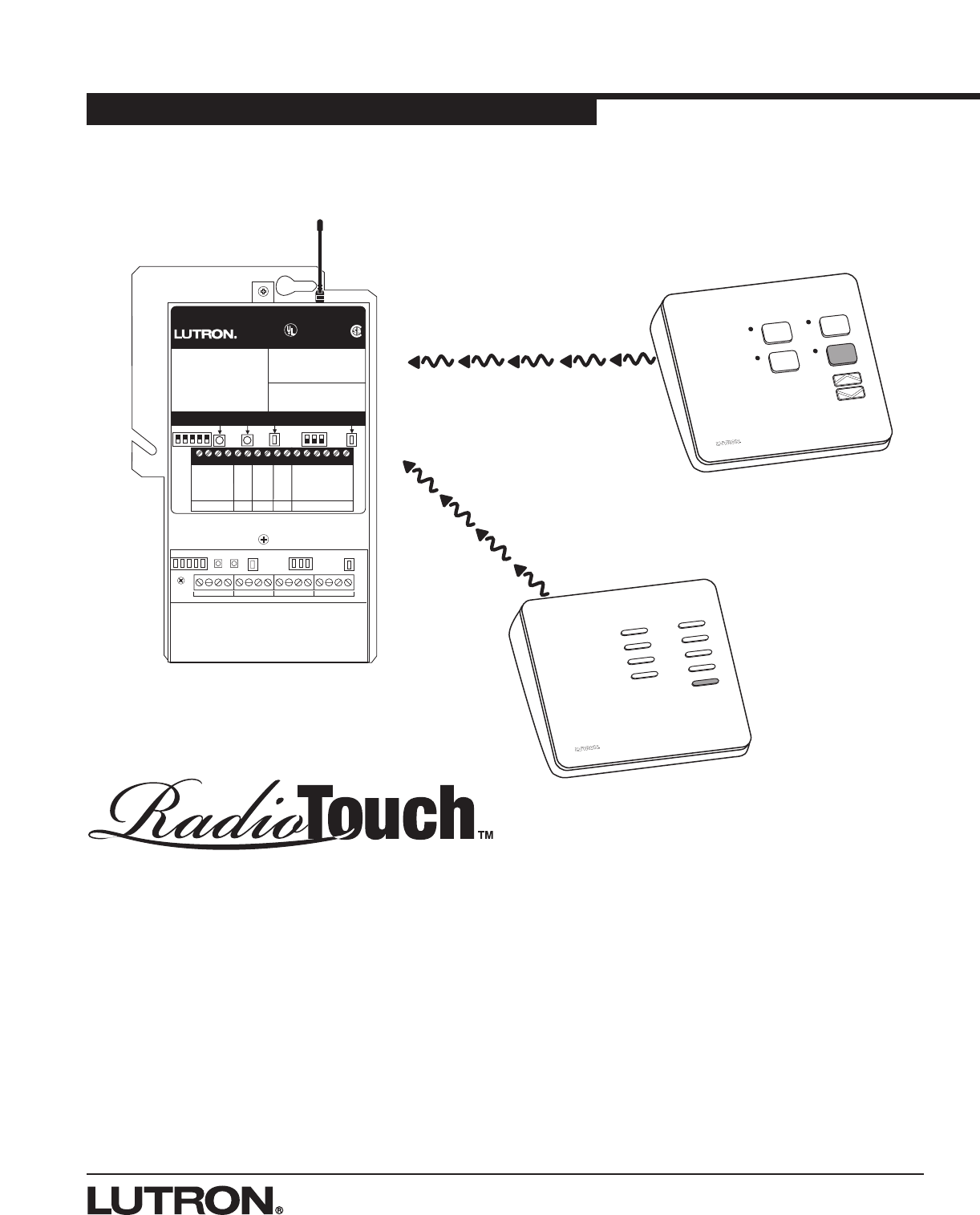
Tabletop Transmitters
A Step-by-Step Guide for Installing, and Operating
Tabletop Transmitters for use with a Lutron RadioTouchTM
Visual Environment Control System
1234 5678 9101112 13141516
CLASS 2 LOW VOLTAGE WIRING
12345 Power Status Program Burn-In
123
Sivoia Cntrl 1
Sivoia Cntrl 2
RTA-RX-F-SC
Radio Frequency Controller LISTED 243C
Ind. Cont. Eq.
Coopersburg, PA 18036
STATUS INDICATOR OPERATION
ON - Burn-in Mode
Slow Blink -Normal Operation Mode
Fast Blink - Program Mode
Very Fast Blink - Receiving RF Data
RadioTouch
12345678910
11 12 13 14 15 16
Occ. Com
Signal
15V
24V
Circuit Com
Sw Closure 1
Sw Closure 2
Sw Closure 3
Sw Closure 4
Sw Closure 5
Closure Com
0-10 Purple
0-10 Gray
Receiver
Settings
Terminal connections
are Class 2.
TM
Occ. Sensor 0-10 V Shade Swit c h C losures
12345
Powered
When Lit
Status
Indicator
Program
Button
Burn-in
Button
RECEIVER SWITCH SETTINGS
1. UP-Preset Lock DN.-Preset Adj.
2. UP-Occ. Sensor DN.-Emerg. Set.
3. UP-FDB Mode DN.-ECO Mode
4. UP-OFF DN.-Min. Light
5. UP-Auto ON DN.-Manual ON
See Installers Guide for System
Addressing and Programming Instructions
®
123
Shade
Settings
SHADE SWITCH SETTINGS
1. UP-A/C Shades DN.-Normal Oper.
PS Signal
© 2000-2002 Lutron Electronics Co., Inc.
2RadioTouch Tabletop Transmitter Addendum
Hardware Installation
RadioTouch
1234 5678 9101112 13141516
CLASS 2 LOW VOLTAGE WIRING
12345 Power Status Program Burn-In
123
Sivoia Cntrl 1
Sivoia Cntrl 2
RTA-RX-F-SC
Radio Frequency Controller LISTED 243C
Ind. Cont. Eq.
Coopersburg, PA 18036
STATUS INDICATOR OPERATION
ON - Burn-in Mode
Slow Blink -Normal Operation Mode
Fast Blink - Program Mode
Very Fast Blink - Receiving RF Data
RadioTouch
12345678910
11 12 13 14 15 16
Occ. Com
Signal
15V
24V
Circuit Com
Sw Closure 1
Sw Closure 2
Sw Closure 3
Sw Closure 4
Sw Closure 5
Closure Com
0-10 Purple
0-10 Gray
Receiver
Settings
Terminal connections
are Class 2.
TM
Occ. Sensor 0-10 V Shade Switch Closures
12345
Powered
When Lit
Status
Indicator
Program
Button
Burn-in
Button
RECEIVER SWITCH SETTINGS
1. UP-Preset Lock DN.-Preset Adj.
2. UP-Occ. Sensor DN.-Emerg. Set.
3. UP-FDB Mode DN.-ECO Mode
4. UP-OFF DN.-Min. Light
5. UP-Auto ON DN.-Manual ON
See Installers Guide for System
Addressing and Programming Instructions
®
123
Shade
Settings
SHADE SWITCH SETTINGS
1. UP-A/C Shades DN.-Normal Oper.
PS Signal
© 2000-2002 Lutron Electronics Co., Inc.
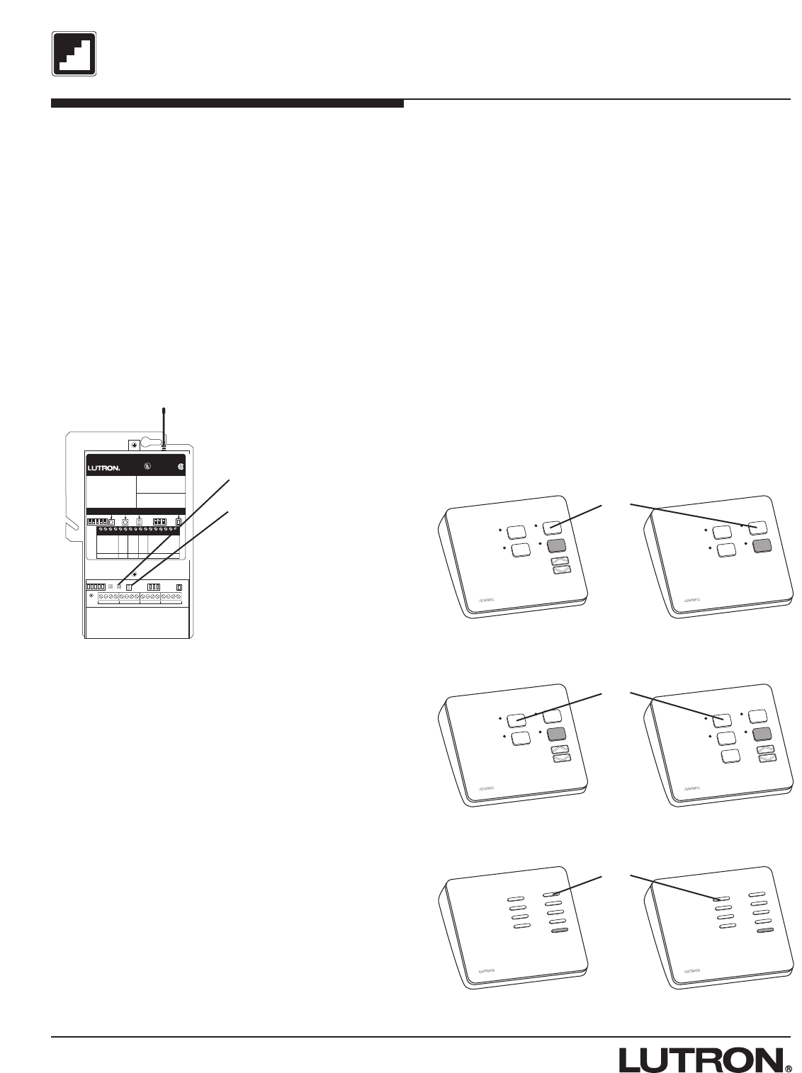
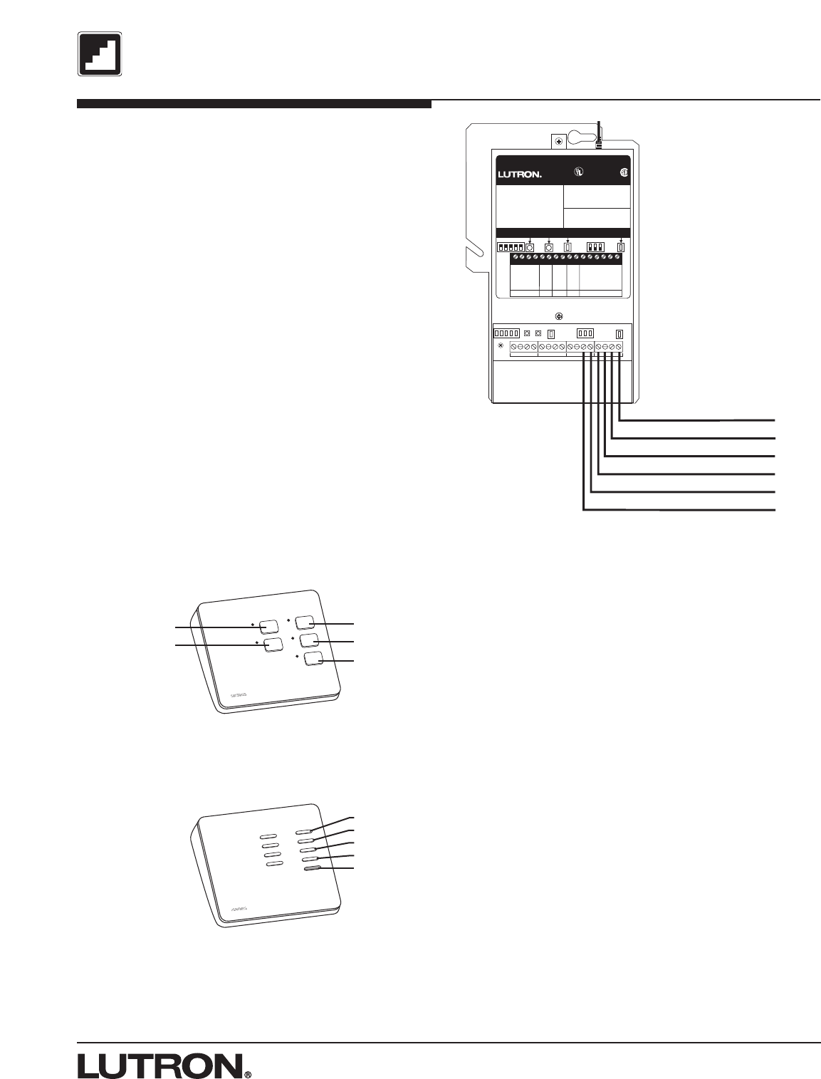
Addressing a Tabletop Transmitter
Each column of buttons on the tabletop transmitter
must be addressed to the Controller that you wish to
control with that column.
Addressing Columns of Buttons
Step A - Press and release the programming button on
the Controller. After the button is pressed the lights will
cycle up and down for 3 seconds to notify you that you
are in programming mode, and settle at 50% light
output. If you are using an RTA-RX-SW the lights will
cycle OFF and ON. The Status LED will be in fast blink
mode.
Press and hold
this button
Step B - While in programming mode press the
corresponding button in the column that you want to
control the receiver and hold for 5 seconds (see
Transmitter diagrams below). The Controller will flash
or cycle the lights OFF and ON when the transmitter is
added. If no lights are being controlled by the receiver,
you will not get visual feedback.
Step C - Press the programming button again to exit
from programming mode. The lights will go to high end
and the Status LED will return to slow blink mode. If
you are using an RTA-RX-SW the lights will cycle OFF
and ON. To test the tabletop transmitter for lights, press
any button in the column added on the tabletop
transmitter and verify that the lights respond. For
Sivoia®shades, press any button and see that the
shades move. If no response return to step A and be
sure to hold the buttons for 5 seconds while in step B.
Step D - Repeat steps A through C for each column
you need to address to a Controller.
Programming button
Status LED
Step A & C
Press and hold
this button
Press and hold
this button
Step B - Columns of buttons
Two button Switch Closure Three button Switch Closure
Dimmable Lights Non-dim Lights
Four button Switch Closure Five button Switch Closure
3
RadioTouch Tabletop Transmitter Addendum
Hardware Installation
RadioTouch
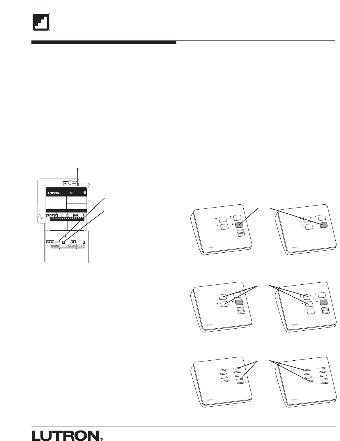
Deleting a Tabletop Transmitter
Each column of buttons on the tabletop transmitter
must be deleted separately from the Controller that you
no longer wish to control.
Deleting Columns of Lights
Step A - Press and release the programming button on
the Controller. After the button is pressed the lights will
cycle up and down for 3 seconds to notify you that you
are in programming mode, and settle at 50% light
output. If you are using an RTA-RX-SW the lights will
cycle OFF and ON. The Status LED will be in fast blink
mode.
Step B - While in programming mode press the
corresponding buttons in the column that you want to
delete from the Controller and hold for 5 seconds (see
Transmitter diagrams below). The Controller will flash
the lights when the transmitter is deleted. If no lights
are being controlled by the Controller, you will not get
visual feedback.
Step C - Press the programming button again to exit
from programming mode. The lights will go to high end
or turn ON, and the Status LED will return to slow blink
mode. To test the Tabletop Transmitter press any button
on the transmitter in the column that has been deleted
and verify that the lights or shades do not respond.
Step D - Repeat for each row you need to delete from
a Controller.
1234 5678 9101112 13141516
CLASS 2 LOW VOLTAGE WIRING
12345 Power Status Program Burn-In
123
Sivoia Cntrl 1
Sivoia Cntrl 2
RTA-RX-F-SC
Radio Frequency Controller LISTED 243C
Ind. Cont. Eq.
Coopersburg, PA 18036
STATUS INDICATOR OPERATION
ON - Burn-in Mode
Slow Blink -Normal Operation Mode
Fast Blink - Program Mode
Very Fast Blink - Receiving RF Data
RadioTouch
12345678910
11 12 13 14 15 16
Occ. Com
Signal
15V
24V
Circuit Com
Sw Closure 1
Sw Closure 2
Sw Closure 3
Sw Closure 4
Sw Closure 5
Closure Com
0-10 Purple
0-10 Gray
Receiver
Settings
Terminal connections
are Class 2.
TM
Occ. Sensor 0-10 V Shade Switch Closures
12345
Powered
When Lit
Status
Indicator
Program
Button
Burn-in
Button
RECEIVER SWITCH SETTINGS
1. UP-Preset Lock DN.-Preset Adj.
2. UP-Occ. Sensor DN.-Emerg. Set.
3. UP-FDB Mode DN.-ECO Mode
4. UP-OFF DN.-Min. Light
5. UP-Auto ON DN.-Manual ON
See Installers Guide for System
Addressing and Programming Instructions
®
123
Shade
Settings
SHADE SWITCH SETTINGS
1. UP-A/C Shades DN.-Normal Oper.
PS Signal
© 2000-2002 Lutron Electronics Co., Inc.
Press and hold
this button
Programming button
Status LED
Step A & C
Press and hold
these buttons
Press and hold
these buttons
Step B - Columns of buttons
Two button Switch Closure Three button Switch Closure
Dimmable Lights Non-dim Lights
Four button Switch Closure Five button Switch Closure
4RadioTouch Tabletop Transmitter Addendum
Hardware Installation
RadioTouch
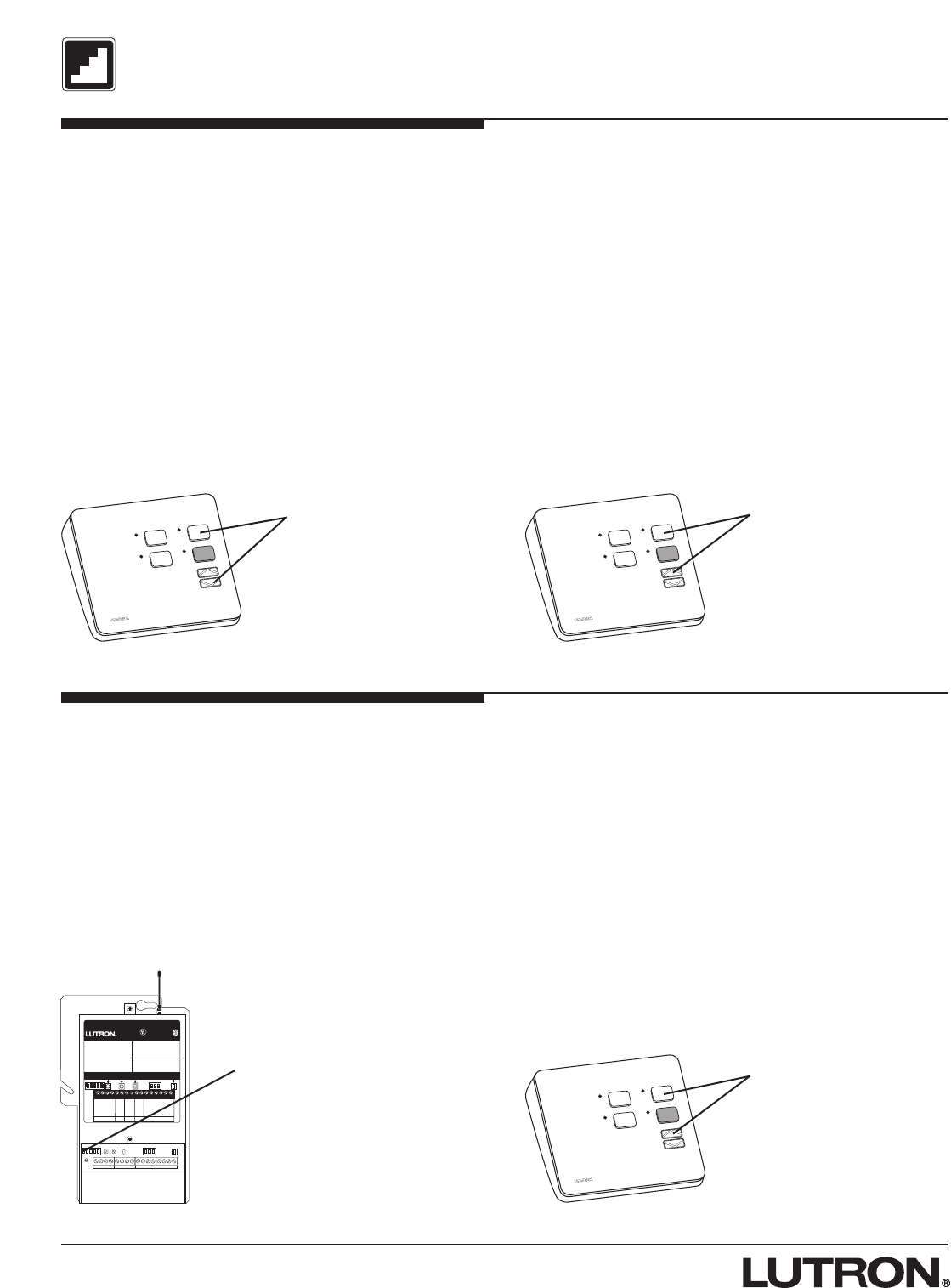
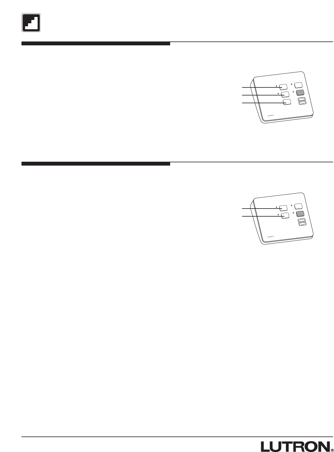
Setting the ON light level of a two
button, dimmable lighting column -
Remote Method
Note: No DIP switches need to be switched to perform
this operation.
Step A - Press and hold the ON and the lower buttons
for 5 seconds. The lights will flash to notify you that you
are in Preset Adjust Mode, and settle at 100% light
level.
Step B - Using the raise/lower buttons in that column
on the transmitter controlling the Controller that you are
adjusting, set the lights at the new ON level.
Step C - Press and hold the ON and raise buttons for 5
seconds. The lights will flash to notify you that the ON
level has changed.
Step D - Press and hold the ON and the lower buttons
for 5 seconds to exit Preset Adjust Mode. The lights will
flash and return to their maximum light level. Test the
ON button to make sure the light level is correct. If not,
repeat steps A through D.
Notes:
•The Controller will not react to preset button presses
from any transmitter while the Controller is in Preset
Adjust Mode.
•Preset light levels may be affected by a photosensor
input. As ambient light increases / decreases the
preset light levels will scale accordingly.
Press and hold
these two buttons
for 5 seconds
Step A & D Step C
Press and hold
these two buttons
for 5 seconds
Press and hold
these two buttons
for 5 seconds
Setting the ON light level of a two
button, dimmable lighting column -
DIP Switch Method
Step A - Flip DIP switch #1 down on the Controller.
After the switch is flipped the Controller will be in Preset
Adjust Mode. (If a photosensor is connected to this
Controller your lights may change level when DIP
switch #1 is flipped.)
Step B - Using the raise/lower buttons on the
transmitter controlling the Controller that you are adjust-
ing, set the lights at the new ON level.
Step C - Press and hold the ON and raise buttons for 5
seconds. The lights will flash to notify you that the ON
level has changed.
Step D - Flip DIP switch #1 back up to exit Preset
Adjust Mode.
Notes:
•The Controller will not react to preset button presses
from the transmitter while the Controller DIP switch
#1 is flipped to the down position.
•Preset light levels may be affected by a photosensor
input. As ambient light increases / decreases the
preset light levels will scale accordingly.
Step A & D Step C
1234 5678 9101112 13141516
CLASS 2 LOW VOLTAGE WIRING
12345 Power Status Program Burn-In
123
Sivoia Cntrl 1
Sivoia Cntrl 2
RTA-RX-F-SC
Radio Frequency Controller LISTED 243C
Ind. Cont. Eq.
Coopersburg, PA 18036
STATUS INDICATOR OPERATION
ON - Burn-in Mode
Slow Blink -Normal Operation Mode
Fast Blink - Program Mode
Very Fast Blink - Receiving RF Data
RadioTouch
12345678910
11 12 13 14 15 16
Occ. Com
Signal
15V
24V
Circuit Com
Sw Closure 1
Sw Closure 2
Sw Closure 3
Sw Closure 4
Sw Closure 5
Closure Com
0-10 Purple
0-10 Gray
Receiver
Settings
Terminal connections
are Class 2.
TM
Occ. Sensor 0-10 V Shade Sw itc h Closures
12345
Powered
When Lit
Status
Indicator
Program
Button
Burn-in
Button
RECEIVER SWITCH SETTINGS
1. UP-Preset Lock DN.-Preset Adj.
2. UP-Occ. Sensor DN.-Emerg. Set.
3. UP-FDB Mode DN.-ECO Mode
4. UP-OFF DN.-Min. Light
5. UP-Auto ON DN.-Manual ON
See Installers Guide for System
Addressing and Programming Instructions
®
123
Shade
Settings
SHADE SWITCH SETTINGS
1. UP-A/C Shades DN.-Normal Oper.
PS Signal
© 2000-2002 Lutron Electronics Co., Inc.
Flip DIP switch
#1 to the down
position
5
RadioTouch Tabletop Transmitter Addendum
Hardware Installation
RadioTouch
1234 5678 9101112 13141516
CLASS 2 LOW VOLTAGE WIRING
12345 Power Status Program Burn-In
123
Wiring output switch closures to
other equipment (RTA-RX-F-SC only)
The RadioTouch controller has the ability to provide 5
momentary dry output switch closures. These closures
can be used to operate AC shades, Motorized
Projection Screens, or other equipment designed to
accept momentary dry switch closures.
A column of 5 buttons on a Tabletop Transmitter
correspond to Switch Closures 1 through 5 on the
Controller.
A two button column on a Tabletop Transmitter will
activate Switch Closures 2 and 4.
A three button column on a Tabletop Transmitter will
activate Switch Closures 2, 4, and 3, in that order. (See
diagrams below.)
The switch closure outputs on the RadioTouch
Controller provide a momentary dry closure for 0.250
seconds to other equipment. The closure terminals are
shown below.
Switch Closure Outputs – Not to
exceed 30VDC and 1/3 Amp.
Closure 2
Closure 4
Closure 2
Closure 4
Closure 3
Sivoia Cntrl 1
Sivoia Cntrl 2
RTA-RX-F-SC
Radio Frequency Controller LISTED 243C
Ind. Cont. Eq.
Coopersburg, PA 18036
STATUS INDICATOR OPERATION
ON - Burn-in Mode
Slow Blink -Normal Operation Mode
Fast Blink - Program Mode
Very Fast Blink - Receiving RF Data
RadioTouch
12345678910
11 12 13 14 15 16
Occ. Com
Signal
15V
24V
Circuit Com
Sw Closure 1
Sw Closure 2
Sw Closure 3
Sw Closure 4
Sw Closure 5
Closure Com
0-10 Purple
0-10 Gray
Receiver
Settings
Terminal connections
are Class 2.
TM
Occ. Sensor 0-10 V Shade Switch Closures
12345
Powered
When Lit
Status
Indicator
Program
Button
Burn-in
Button
RECEIVER SWITCH SETTINGS
1. UP-Preset Lock DN.-Preset Adj.
2. UP-Occ. Sensor DN.-Emerg. Set.
3. UP-FDB Mode DN.-ECO Mode
4. UP-OFF DN.-Min. Light
5. UP-Auto ON DN.-Manual ON
See Installers Guide for System
Addressing and Programming Instructions
®
123
Shade
Settings
SHADE SWITCH SETTINGS
1. UP-A/C Shades DN.-Normal Oper.
PS Signal
© 2000-2002 Lutron Electronics Co., Inc.
Switch Closure Common
Switch Closure 5
Switch Closure 4
Switch Closure 3
Switch Closure 2
Switch Closure 1
Tabletop Button Functions
Two and Three button Switch Closures
Closure 1
Closure 2
Closure 3
Closure 4
Closure 5
Five button Switch Closures
6RadioTouch Tabletop Transmitter Addendum
Hardware Installation
RadioTouch
Open
Stop
Close
Tabletop Button Functions
Setup for AC Motorized Window
Treatments (RTA-RX-F-SC only)
Make sure that the RadioTouch Controller is properly
wired. Refer to the RadioTouch Installer’s Guide (P/N
030-200) for detailed wiring information.
Step A - On the RadioTouch Controller, flip SHADE
SETTINGS DIP SWITCH #1 UP for open, close, and
stop functionality.
Step B - Make sure appropriate transmitters are added
to the Controller. See page 2 for Addressing Tabletop
Transmitters to Controllers. Three button Switch Closure
Up
Down
Tabletop Button Functions
Setup for AC Motorized Projection
Screens (RTA-RX-F-SC only)
Make sure that the RadioTouch Controller is properly
wired. Refer to the RadioTouch Installer’s Guide (P/N
030-200) for detailed wiring information.
Step A - On the RadioTouch Controller, flip SHADE
SETTINGS DIP SWITCH #1 DOWN for up and down
functionality.
Step B - Make sure appropriate transmitters are added
to the Controller. See page 2 for Addressing Tabletop
Transmitters to Controllers. Two button Switch Closure

7
RadioTouch Tabletop Transmitter Addendum
Notes

Lutron Electronics Co., Inc., reserves the right to make
improvements or changes in its products without prior
notice. Although every attempt is made to ensure that
this information is accurate and up to date, please
check with Lutron to confirm product availability, latest
specifications and suitability for your application.
World Headquarters
Lutron Electronics Co., Inc.
7200 Suter Road
Coopersburg, PA 18036-1299 U.S.A.
TOLL FREE: (800) 523-9466 (U.S.A., Canada, and
the Caribbean)
Tel: (610) 282-3800; International 1610 282-3800
Fax: (610) 282-3090; International 1610 282-3090
European Headquarters
Lutron EA LTD
Lutron House
6 Sovereign Close
Wapping
London, E1 9HW England
FREEPHONE: 0800 282107 (U.K.)
Tel: (0171) 702-0657; International 44-171-702-0657
Fax: (0171) 480-6899; International 44-171-480-6899
Japan Sales Office
Lutron Asuka Co., Ltd
No. 16 Kowa Bldg. 4F
1-9-20 Akasaka, Minato-ku
Tokyo 107-0052 Japan
TOLL FREE: (0120) 083417 (Japan)
Tel: (03) 5575-8411; International 81-3-5575-8411
Fax: (03) 5575-8420; International 81-3-5575-8420
Hong Kong Sales Office
Tel: 2104-7733; International 852-2104-7733
Fax: 2104-7633; International 852-2104-7633
LIMITED WARRANTY
Lutron will, at its option, repair or replace any unit that
is defective in materials or manufacture within one year
after purchase. For warranty service, return unit to
place of purchase or mail to Lutron at 7200 Suter Rd.,
Coopersburg, PA 18036-1299, postage pre-paid.
THIS WARRANTY IS IN LIEU OF ALL OTHER
EXPRESS WARRANTIES, AND THE IMPLIED WAR-
RANTY OF MERCHANTABILITY IS LIMITED TO ONE
YEAR FROM PURCHASE. THIS WARRANTY DOES
NOT COVER THE COST OF INSTALLATION,
REMOVAL OR REINSTALLATION, OR DAMAGE RE-
SULTING FROM MISUSE, ABUSE, OR DAMAGE
FROM IMPROPER WIRING OR INSTALLATION. THIS
WARRANTY DOES NOT COVER INCIDENTAL OR
CONSEQUENTIAL DAMAGES. LUTRON’S LIABILITY
ON ANY CLAIM FOR DAMAGES ARISING OUT OF
OR IN CONNECTION WITH THE MANUFACTURE,
SALE, INSTALLATION, DELIVERY, OR USE OF THE
UNIT SHALL NEVER EXCEED THE PURCHASE
PRICE OF THE UNIT.
This warranty gives you specific legal rights, and you
may have other rights which vary from state to state.
Some states do not allow the exclusion or limitation of
incidental or consequential damages, or limitation on
how long an implied warranty may last, so the above
limitations may not apply to you.
These products may be covered by one of more
of the following U.S. patents: 4,663,570; 4,751,399;
4,783,581; 4,835,343; 4,894,587; 5,001,386; 5,041,763;
5,055,742; 5,142,199; 5,144,205; 5,173,643; 5,224,029;
5,248,919; 5,281,961; 5,293,097; 5,309,068; 5,357,170;
5,399,940; 5,555,150; 5,633,540; 5,637,930; 5,736,965;
5,798,581; 5,838,226; 5,841,239; 5,848,054; 5,864,212;
5,905,442; 5,942,727; 5,962,979; 5,982,103; 6,111,368;
6,313,588; 6,346,781; RE37,135; 6,225,760; DES
353,798; DES 364,141; DES 378,814; DES 389,461;
DES 389,805; DES 395,037; DES 404,013; DES
422,969; DES 428,855; DES 436,579; DES 439,220;
and corresponding foreign patents. Other U.S. and
foreign patents may be pending.
Lutron, is a registered trademark and RadioTouch is a
trademark of Lutron Electronics Co., Inc.
Technical and Sales Assistance
If you have questions concerning the installation or
operation of this product, call the toll-free Lutron
Technical Support Center. Please provide exact
model number when calling.
U.S.A., Canada, and the Caribbean
(800) 523-9466 27 hrs/7 days
other countries
(610) 282-3800 8:00a.m. – 8:00p.m. ET
Our address on the web is http://www.lutron.com
© 2003 Lutron Electronics Co., Inc.
MADE AND PRINTED IN U.S.A.
P/N 031-xxx Rev. A 12/03