Lutron Electronics 0118 Dimmer Module User Manual 20180912 v1 11 Install 041675a
Lutron Electronics Company Inc Dimmer Module 20180912 v1 11 Install 041675a
User Manual_20180912_v1 - 11_Install_041675a
041588
Rev. A
08/2018
PowPak | Installation
Control Module with EcoSystem
Test
Link Cal. +
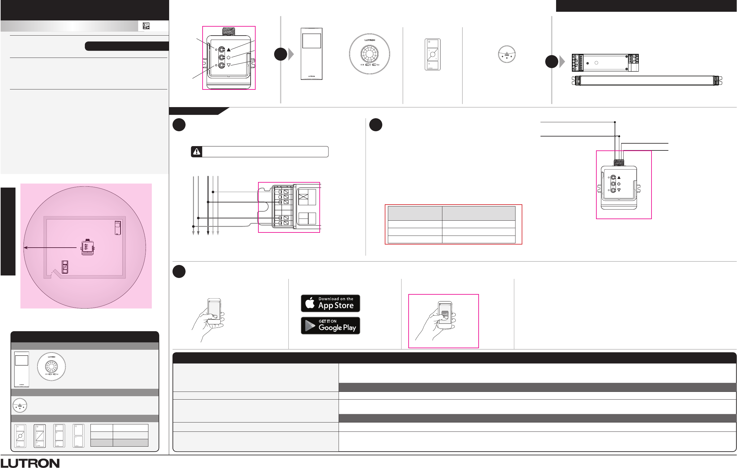
For each system, ensure that you have:
One PowPak Control Module At least one Wireless Transmitter At least one EcoSystem LED Driver or Fluorescent Ballast
Required Components
Radio Powr Savr Occupancy/Vacancy Sensor
(10 maximum)
Radio Powr Savr Daylight Sensor
(1 maximum)
Pico Remote Control
(10 maximum)
64 mA for the control lines. May be pre-installed in light fixture.
Note: All drivers and ballasts used with Vive wireless controls must comply with the
limits for a Class A device, pursuant to Part 15 of the FCC rules.
PowPak Control Module with EcoSystem
(1 maximum)
Raise
Toggle
Lower
Top LED
Consult third-party DALI fixtures installation guide for fixture-specific wiring. This device can
be installed on a fixture / troffer, junction box, or marshalling box using the conduit nut or with
mounting screws. The device must NOT be mounted inside a fixture / troffer or other metallic
enclosure. Improper installation can result in degraded wireless communication, intermittent or
sustained communication failures, and will not be covered under warranty. For mounting and
wiring best practices see Lutron Application Note #620 (P/N 048620).
+
Occupancy Sensors
Daylight Sensor
Wireless Controls
Occupied: All lights 100%.
Unoccupied: All lights off.
Test
Link Cal.
All lights dim in response to daylight.
On All lights 100%
Favorite All lights 50%
Off All lights off
Default Functionality
2
A
The PowPak Control Module with EcoSystem can be installed on a
fixture / troffer, junction box, or marshalling box using the conduit nut
(provided) or with mounting screws (not provided). Please consult local
and national electric codes for proper installation.
B
Once installed, energize the PowPak Control Module with EcoSystem.
C
Use the Toggle “ u” , Raise “
▲
” and Lower “
Δ
” buttons to verify
control wiring.
English
All Wireless Transmitters must be installed within
9 m (30 ft) of the PowPak Control Module with
EcoSystem.
EcoSystem Control: 18 V- 64 mA
120 – 277 V~ 50 / 60 Hz 80 mA
RMJS-ECO32-SZ
A
Connect mains wiring (hot, neutral) to each fixture.
B
Connect EcoSystem control to each fixture.
1
E1
E2
NEU
HOT
DALI
MAINS
To additional EcoSystem fixtures
Neutral
Line/Hot
E1
E2
+
–
WARNING! Shock Hazard. May result in serious injury or death. Turn off power at circuit
breaker before installing the unit.
Sample LED
driver shown
Important Notes: Please read before installing.
For installation by a qualified electrician in accordance with all local and
national electrical codes.
•Use copper conductors only.
•Check to see that the device type and rating is suitable for the application.
•DO NOT install if product has any visible damage.
•If moisture or condensation is evident, allow the product to dry completely
before installation.
•Operate between 0 °C and 40 °C (32 °F and 104 °F) ambient.
•0% to 90% humidity, non-condensing.
•For indoor use only.
Start Here
X
Vive
Programming with a Vive Hub
3
Mount, Wire, and Install EcoSystem
Devices and Lighting Fixtures
Consult third-party device installation guide
Install PowPak Control Module with
EcoSystem
Suggested Installation Location: Center of room to
ensure proper RF coverage of area.
A
Use an iOS or Android compatible device.
B
Download the Lutron Vive app.
C
Open the app and follow the instructions. Note: For further information on set up, programming, and troubleshooting with a Vive
system, please refer to the installation instructions included with the Vive hub or visit
www.lutron.com/vive
Note: For programming the PowPak Control Module with EcoSystem without a Vive hub
see reverse side.
Customer Assistance www.lutron.com/support
Troubleshooting www.lutron.com /vive
Ballasts cannot be controlled locally from PowPak Control Module
with EcoSystem.
• Ensurethatthebreaker(s)tothePowPak Control Module are energized.
• EnsurethattheEcoSystem control lines are wired to the lighting fixture(s).
Reset to factory defaults.
Lights do not dim as expected. • EnsurethatEcoSystem control lines are wired properly.
Lights do not respond to Wireless Transmitter(s).
•Ensure that the breaker(s) to the PowPak Control Module with EcoSystem and drivers/ballasts are energized.
• EnsurethatWirelessTransmittersareassociatedtothePowPak Control Module with EcoSystem.
Reset to factory defaults.
Lights are unstable at low-end or flash/flicker at turn-on or turn-off. • Adjustthelow-endtrim.
Wireless Transmitter(s) cannot be associated to PowPak Control
Module with EcoSystem.• ThemaximumnumberofWirelessTransmittershavebeenassociatedtothePowPak Control Module with EcoSystem. To remove a previously set up Wireless
Transmitter, tap a Wireless Transmitter button three times; on the third tap hold for three seconds and then tap three more times.
Part of the Vive Family
vive.lutron.com
X
EcoSystem to Fixtures
E1 (Violet)
E2 (Violet/White)
Neutral (White)
Line / Hot (Black)
Lutron Electronics Co., Inc.
7200 Suter Road
Coopersburg, PA 18036
041675
Rev. A
08/2018
Bottom LED
9 m
maximum
Radio Powr
Savr Occupancy
Sensor
Pico
Remote
Control
PowPak
Control Module
Install in center of room
to maximize RF coverage.
PowPak
Control
Module
Wire Gauge Maximum DALI-compliant
Bus Wire Length
1.5 mm2 (14 AWG) 300 m
0.75 mm2 (18 AWG) 150 m
0.5 mm2 (20 AWG) 100 m
PowPak | Installation
Programming without a Vive Hub
Control Module with EcoSystem
Part of the Vive Family
Start Here
Lutron, Pico, and PowPak are trademarks of Lutron Electronics Co., Inc., registered in the U.S. and other countries. Radio Powr Savr and Vive are trademarks of Lutron Electronics Co., Inc. App Store is a trademark of Apple Inc., registered in the U.S. and other countries. iOS is a registered trademark of Cisco in the U.S. and other countries and is used under license.
Android, Google Play and the Google Play logo are trademarks of Google Inc. DALI is a trademark of ZVEI. ©2013 – 2018 Lutron Electronics Co., Inc.
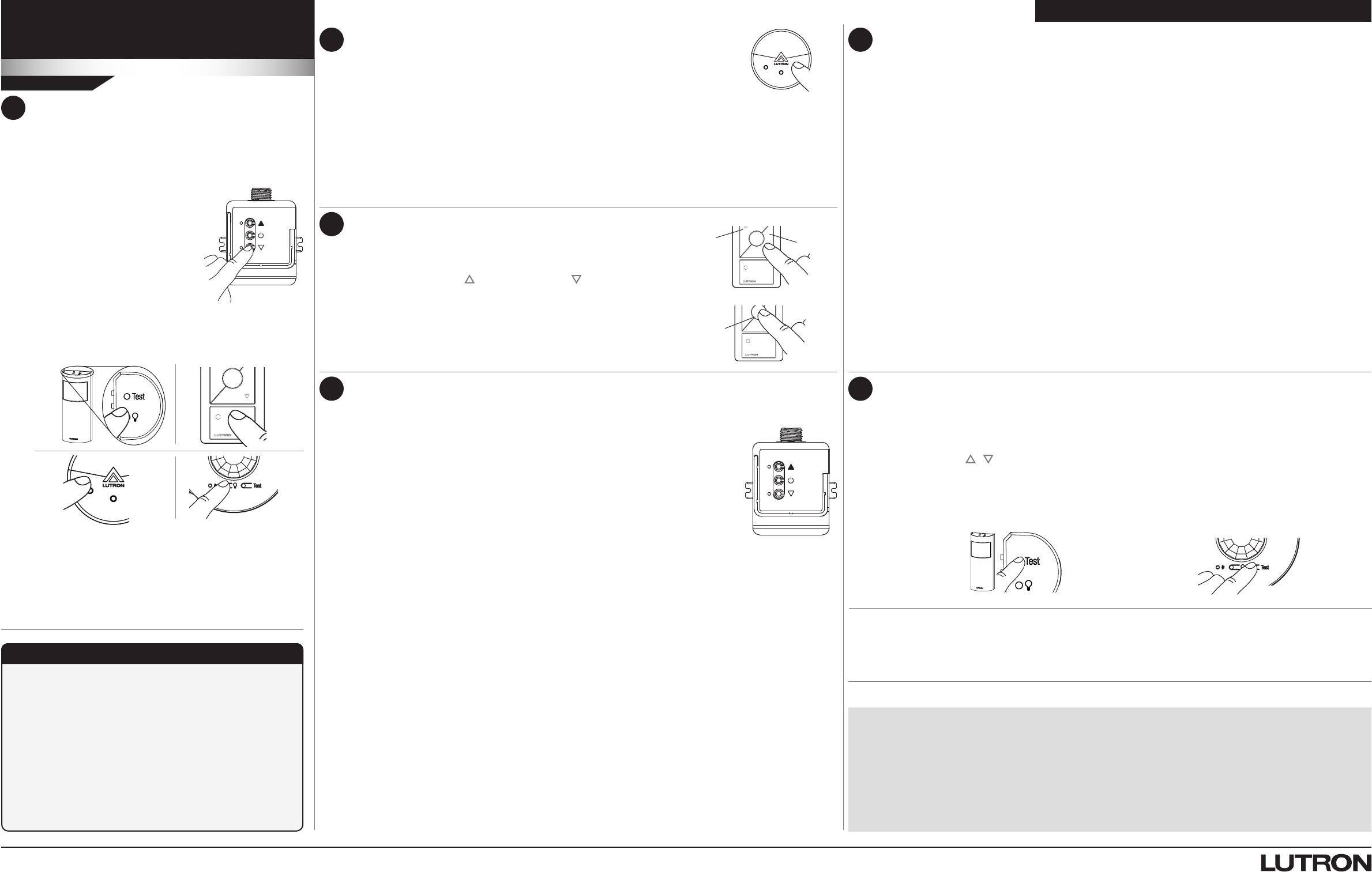
A On PowPak Control Module with
EcoSystem, hold Toggle button
“ u” for 6 seconds until lights
flash.
Both LEDs will begin flashing
twice per second.
Associate Wireless Transmitters to
PowPak Control Module with EcoSystem
Before beginning this step, make sure that there are no
other PowPak modules being set up within the same
building. It is possible that wireless transmitters from other
systems can be incorrectly associated to this module.
1
C On PowPak Control Module with EcoSystem, hold
Toggle button “ u” for 6 seconds to save association.
Lights will return to high end and LEDs will stop
flashing.
B Hold the indicated button on each transmitter for
6seconds. Lights will flash to show that wireless
transmitters have been associated. LEDs also flash on
successful association.
Test
Link
Cal.
D Permanently install wireless transmitters
(consult individual component installation guides for
information).
Raise Lower
Favorite
Set a Favorite Light Level (Optional)
For Pico remote controls with a Favorite Button.
A
Adjust lights to desired level:
Use the Raise button “ ” or Lower button “ ” on the Pico remote
control.
B
Save favorite level:
Press and hold the Favorite button for 6seconds. The load will flash
3 times to confirm that the Favorite level is saved.
3
Low-End Trim
A
Enter low-end trim adjustment mode:
Press and hold the Lower button “
Δ
” on the fixture control for 12 seconds.
The lights will flash and the bottom LED will begin flashing.
B
Adjust the low-end trim:
Use the Raise button “▲
” and Lower button “
Δ
” on the control module to adjust and set the lights
to the desired low-end (0.1 to 45%).
C
Save the low-end trim:
Press and hold the Toggle button “ u” for 6seconds to save setting.
The bottom LED will begin flashing and then turn solid to indicate new level has been saved.
High-End Trim
A
Enter high-end trim adjustment mode:
Press and hold the Raise button “▲
” on the fixture control for 12seconds.
The lights will flash and the top LED will begin flashing.
B
Adjust the high-end trim:
Use the Raise button “▲
” and Lower button “
Δ
” on the control module to adjust and set the lights
to the desired high-end (55 to 100%).
C
Save the high-end trim:
Press and hold the Toggle button “ u” for 6seconds to save setting.
The load status LED will begin flashing and then turn solid to indicate new level has been saved.
Set Low-End Trim and High-End Trim (Optional)
For best results, minimize the amount of sunlight entering the room before performing the
following procedures.
Notes
Depending on the fixture manufacturer or load, low-end trim and high-end trim may
need to be adjusted.
• Trimlow-endtoensureastablelightlevelbecausesomeloadswillickerordropout
if trimmed too low.
• Besurethatyoucanturnonthelightstothelow-endtrimlevelwithoutanyabnormal
operation.
• Thefactorydefaulthigh-endtrimissuitableformostapplicationsbutcanbeadjusted
as desired.
4
5Set Minimum Light Level (Optional)
Certain applications (e.g., hallways), may require that the lights never turn off. For these areas,
activate Minimum Light Level mode.
A
Enter minimum light level adjustment mode:
Press and hold Toggle button “ u” and Lower button “
Δ
” for 12 seconds. Lights will flash
high-low-high and both LEDs will begin flashing.
If lights stop flashing and turn off, the minimum light level is set to OFF (default).
If lights stop flashing and go to low-end, the minimum light level is ON and set to low-end.
B
Change the minimum light level:
Press Raise button “
▲
” to set minimum light level to low-end.
Press Lower button “
Δ
” to set minimum light level to OFF.
C
Save the minimum light level:
Press and hold Toggle button “ u” for 6seconds. Both LEDs will quickly flash to indicate that new
level has been saved.
6Set Occupancy Light Levels (Optional)
Note: Unoccupied light level is always the minimum light level and cannot be adjusted.
A
Set desired occupancy light levels:
Use Raise/Lower buttons “
▲
/
Δ
” on the PowPak Control Module with EcoSystem or Raise/
Lower buttons “ / ” on all associated Pico Remote Controls.
B
Save occupancy light levels:
Press and hold Test button for 6 seconds on any associated Radio Powr Savr Occupancy Sensor
without a Lights On button. Release when Sensor lens starts to flash.
Limited Warranty:
www.lutron.com/en-US/ResourceLibrary/warranty/Limited%20Comm.pdf
Calibrate the Radio Powr Savr Daylight Sensor
Daylight Sensor will control all wired fixtures equally.
A
Press and release the “Cal.” button on the Daylight Sensor.
B
Set lights in room to desired light level.
C
Press and hold the “Cal.” button for 6seconds.
D
Exit room for 5 minutes to complete calibration.
Note: When calibration has completed, all lights will flash and begin to respond to daylight.
Multiple Daylight Rows (Optional)
For every row of daylighting a separate PowPak Control Module with EcoSystem must be used.
For detailed setup refer to the tuning section of the Radio Powr Savr Daylight Sensor installation
guide.
• SelectthePowPak Control Module with EcoSystem that you want to adjust by pressing the Toggle button.
Test
Link Cal.
2
Reset Factory Defaults
Note: In some instances, it may be necessary to reset the
PowPak Control Module with EcoSystem and connected
devices back to factory default settings. Before beginning,
make sure that all devices are connected and powered.
A
Triple-tap the Toggle button “ u” on the PowPak Control
Module with EcoSystem and hold until both LEDs begin to
flash slowly; release button.
B
Within 3 seconds of the start of flashing, triple-tap the same
button again and the LEDs will flash rapidly indicating that the
unit has been reset to factory defaults.
Note: Any associations or programming previously set
up with the PowPak will be erased and will need to be
re-programmed.
Customer Assistance:
TEL: +1.844.LUTRON1
FAX: +1.610.282.1243
www.lutron.com/support
Customer Assistance www.lutron.com/support
FCC / IC Information
This device complies with part 15 of the FCC Rules and Industry Canada license-exempt RSS standard(s). Operation is subject to the following
two conditions: (1) This device may not cause interference, and (2) this device must accept any interference, including interference that may cause
undesired operation. Modifications not expressly approved by Lutron Electronics Co., Inc. could void the user’s authority to operate this equipment.
NOTE: This equipment has been tested and found to comply with the limits for a Class B digital device, pursuant to part 15 of the FCC Rules.
These limits are designed to provide reasonable protection against harmful interference in a residential installation. This equipment generates, uses
and can radiate radio frequency energy and, if not installed and used in accordance with the instructions, may cause harmful interference to radio
communications. However, there is no guarantee that interference will not occur in a particular installation. If this equipment does cause harmful
interference to radio or television reception, which can be determined by turning the equipment off and on, the user is encouraged to try to correct
the interference by one or more of the following measures:
•Re-orientorrelocatethereceivingantenna.
•Increasetheseparationbetweentheequipmentandreceiver.
•Connecttheequipmentintoanoutletonacircuitdifferentfromthattowhichthereceiverisconnected.