M Labs Technologies AC05 GPS Tracker User Manual
M-Labs Technologies, LLC GPS Tracker Users Manual
UserManual.wiki
>
M Labs Technologies
>
AC05 User Manual
Users Manual
Navigation menu
Upload a User Manual
Namespaces
Wiki Guide
HTML
PDF
Info
Views
User Manual
Discussion / Help
Navigation
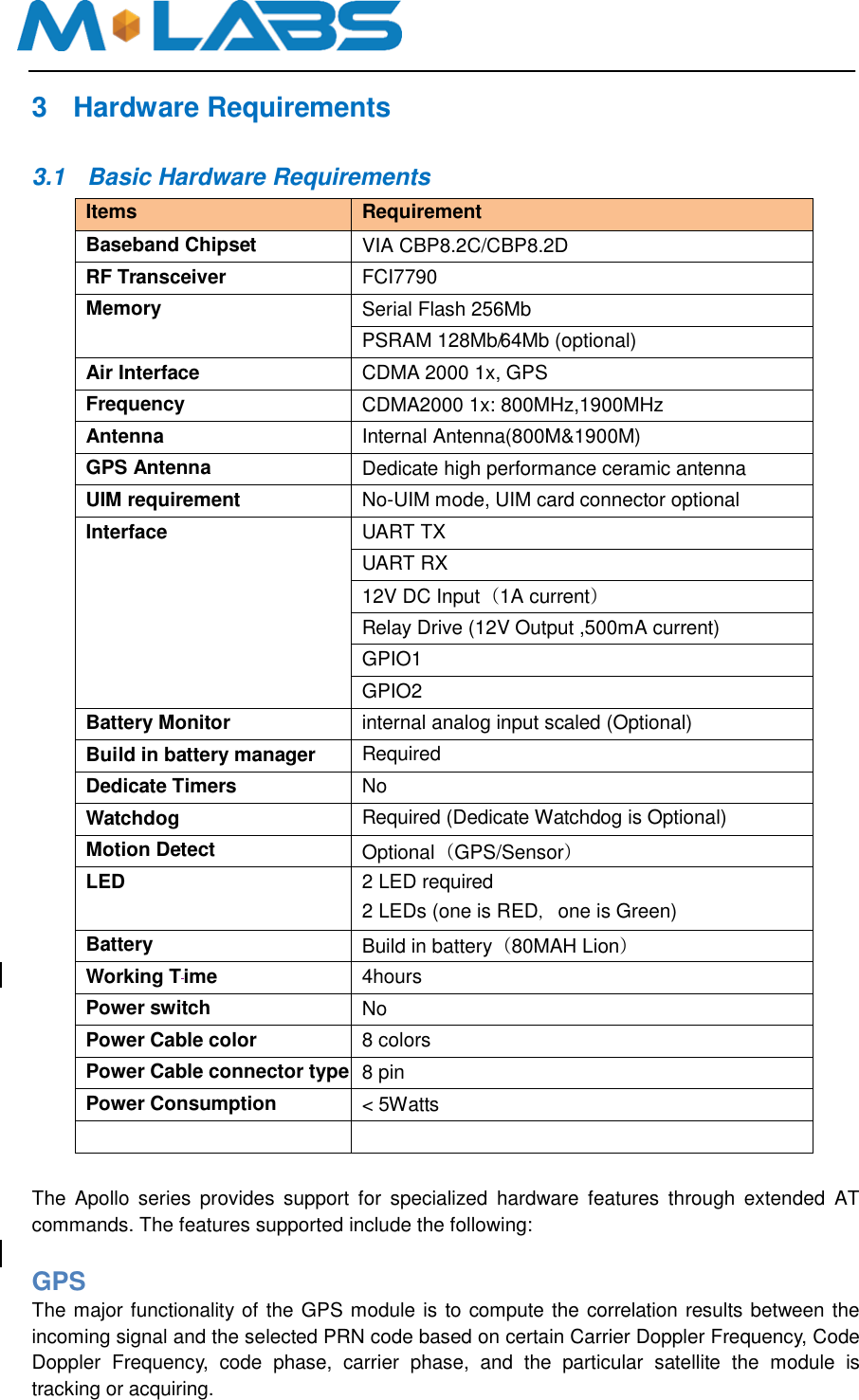
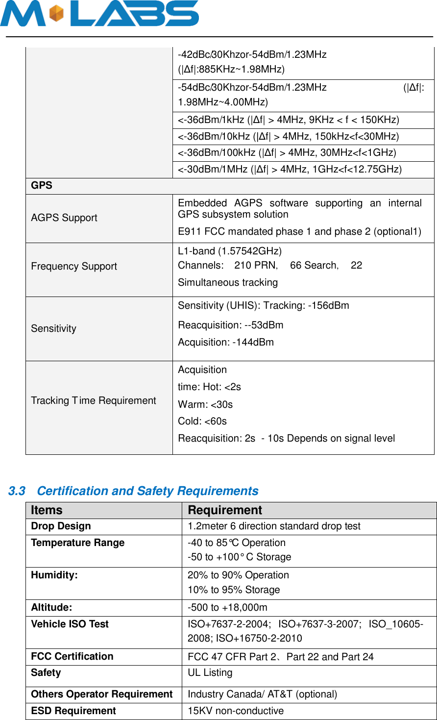
![Watchdog The watchdog is a dedicated part external to the main CPU. Accelerometer (Option) The optional accelerometer can be used for motion detection and driver behavior monitoring. 3.2 Basic RF Performance Requirements Items Requirements Remark TRP free space >= 20 dBm TRP free space TIS free space <= -104dBm TIS free space Antenna loss <= -3 dB TRP-TX Power Conducted Antenna Loss <= -3 dB RX receive sensitivity conducted – TIS Board RF Specification Cellular Band RX Frequency range 869MHz~894MHz Sensitivity -108dBm (FER≤0.5%) Dynamic range -25~-108dBm (FER≤0.5%) Single tone Desensitization -102.4dBm(FER≤1%,-30dBm@±900KHz) Intermediation Spurious Response Attenuation -102.4dBm(FER≤1%,-43dBm@±900 KHz/±1700KHz) -91.4dBm(FER≤1%,-32dBm @±900 KHz/±1700KHz) -80.4dBm(FER≤1%,-21dBm @±900 KHz/±1700KHz) Conducted Spurious Emission <-76dBm/1MHz(RX band) <-61dBm/1MHz( TX band) <-47dBm/30KHz(other frequency) Cellular Band TX Frequency range 824MHz~849MHz Maximum Frequency error ±300KHz Maximum output power 24dBm [-3dB~~+2dB] ; Minimum controlled output power <-50dBm Standby output power <-61dBm Code domain power The code domain power in each inactive code channel shall be 23 dB or more below the total output power measured on both the I and Q data channel combined. T ime reference ±1.0uS Waveform quality >0.944 Range of open loop output (test1:-25dBm/1.23MHz)-47.7±9.5dBm](https://usermanual.wiki/M-Labs-Technologies/AC05/User-Guide-3385948-Page-8.png)
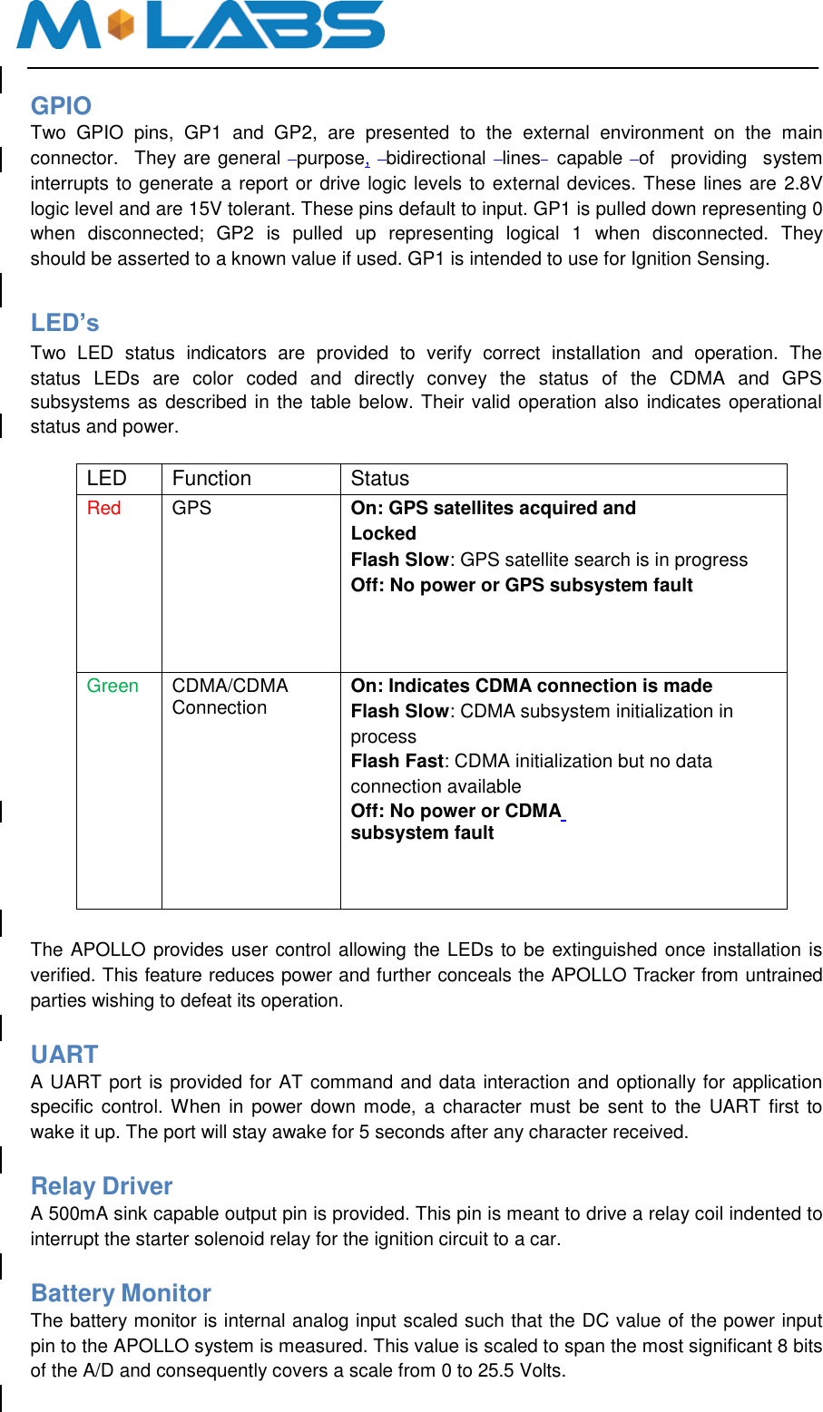
![power (test2:-60dBm/1.23MHz)-7.7±9.5dBm (test3:-93.5dBm/1.23MHz)20.3±9.5dBm Conducted spurious emission -42dBc/30Khzor-54dBm/1.23MHz (|Δf|:1.25MHz~1.98MHz) -50dBc/30Khzor-54dBm/1.23MHz (|Δf|: 1.98MHz~4.00MHz) <-36dBm/1kHz (|Δf| > 4MHz, 9KHz < f < 150KHz,) <-36dBm/10kHz (|Δf| > 4MHz, 150kHz<f<30MHz,) <-36dBm/100kHz (|Δf| > 4MHz, 30MHz<f<1GHz) <-30dBm/1MHz (|Δf| > 4MHz, 1GHz<f<12.75GHz) PCS Band RX Frequency range 1930MHz ~ 1990MHz Sensitivity -108dBm (FER≤0.5%) Dynamic range -25 ~ -108dBm (FER≤0.5%) Single tone Desensitization -102.4dBm(FER≤1%,-40dBm@±1250KHz) Intermediation Spurious Response Attenuation -102.4dBm(FER≤1%,-43dBm@±1250KHz/±2050KHz) Conducted Spurious Emission <-76dBm/1MHz(RX band) <-61dBm/1MHz( TX band) <-47dBm/30KHz(other frequency) PCS Band TX Frequency range 1850MHz ~ 1910MHz Maximum Frequency error ±150KHz Maximum output power 23dBm [-3dB~~+2dB] Minimum controlled output power <-50dBm Standby output power <-61dBm Code domain power The code domain power in each inactive code channel shall be 23 dB or more below the total output power measured on both the I and Q data channel combined. T ime reference ±1.0uS Waveform quality >0.944 Range of open loop output power (test1: -25dBm/1.23MHz) -50.7±9.5dBm Conducted spurious emission (test2: -60dBm/1.23MHz) -10.7±9.5dBm (test3: -91.3dBm/1.23MHz) 20.3±9.5dBm](https://usermanual.wiki/M-Labs-Technologies/AC05/User-Guide-3385948-Page-9.png)