M Labs Technologies AC05 GPS Tracker User Manual
M-Labs Technologies, LLC GPS Tracker Users Manual
Users Manual

User
manual
Contents
1 Introduction ..............................................................................................................................2
2 ID and Tooling Design ................................................................................................................4
3 Hardware Requirements ...........................................................................................................5
3.1 Basic Hardware Requirements .........................................................................................5
3.2 Basic RF Performance Requirements................................................................................7
3.3 Certification and Safety Requirements.............................................................................9
4 Software Requirements...........................................................................................................10
4.1 Basic Software Requirements .........................................................................................10
4.2 Remote Update...............................................................................................................10
4.2.1 Auto Execute ..............................................................................................................10
4.3 Power Modes..................................................................................................................10
4.4 AT Command ..................................................................................................................11
4.5 Report.............................................................................................................................13
4.6 Reset ...............................................................................................................................13
4.6.1 Context Preservation ..................................................................................................13
4.7 Startup Banner ...............................................................................................................13
5 Test Plan ..................................................................................................................................14
5.1 Hardware Test.................................................................................................................14
5.2 Software Test ..................................................................................................................14
1 Introduction
The APOLLO series (including models CDMA/CDMA-B/CDMA-BA/CDMA-G/CDMA-B-
G/CDMA-BA-G) are self-contained vehicle tracking devices that combine GPS location with
CDMA connectivity.
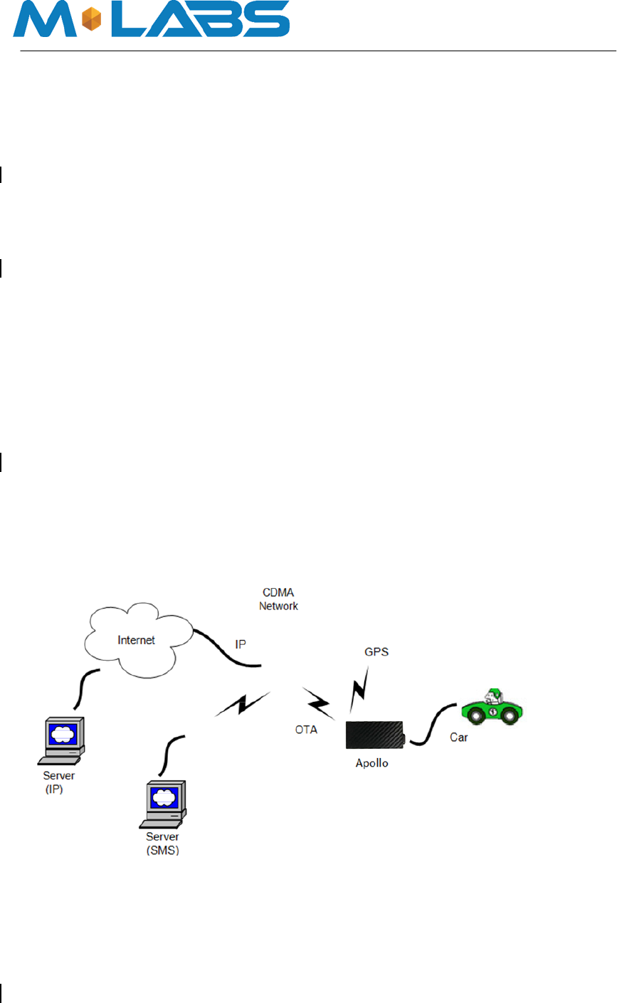
Logically, the APOLLO appears to a user or a server application as a single endpoint device. It
can be queried, updated and configured either through a serial connection, an over the air
CDMA IP connection, or through SMS messaging. The APOLLO series present themselves
over these connections as an enhanced cellular modem with attached functional elements.
These elements include:
□ GPS location engine
□ 2 Ge ne ral Purpose Bidirectional I/ O (GPIO) pins
□ 1 Re lay drive pin out put
□ Serial UART port
□ Input volt age monitor (optional)
□ Tim e rs
□ Wat chdog lockup prot e ct ion (Dedicated watchdog circuit is optional)
□ Fact ory load option for motion detection
Access to these elements and general purpose interfaces is done through an extended AT
command set as defined herein.
Application diagram:
This product is designed based on the VIA CBP8.2 CDMA 1X 800M&1900M Baseband chip,
which includes GPS functionality, ARM CPU and CDMA protocol. This Baseband chip is
connected to 256M serial flash, CDMA 800M/1900M/GPS RF Transceiver, and RF Front
end circuit.
The device includes one dual band antenna(CDMA800&CDMA1900)and one dedicate
GPS antenna.

Marketing Information
Item
Description
Potential market
America
Product Design Requirement
Cost: Entry Level
Expected sample Date
QTY of Samples
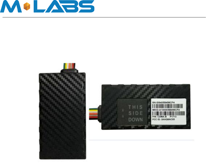
2 ID and Tooling Design
The product appearance is shown as follows:

3 Hardware Requirements
3.1 Basic Hardware Requirements
Items
Requirement
Baseband Chipset
VIA CBP8.2C/CBP8.2D
RF Transceiver
FCI7790
Memory
Serial Flash 256Mb
PSRAM 128Mb/64Mb (optional)
Air Interface
CDMA 2000 1x, GPS
Frequency
CDMA2000 1x: 800MHz,1900MHz
Antenna
Internal Antenna(800M&1900M)
GPS Antenna
Dedicate high performance ceramic antenna
UIM requirement
No-UIM mode, UIM card connector optional
Interface
UART TX
UART RX
12V DC Input(1A current)
Relay Drive (12V Output ,500mA current)
GPIO1
GPIO2
Battery Monitor
internal analog input scaled (Optional)
Build in battery manager
Required
Dedicate Timers
No
Watchdog
Required (Dedicate Watchdog is Optional)
Motion Detect
Optional(GPS/Sensor)
LED
2 LED required
2 LEDs (one is RED,one is Green)
Battery
Build in battery(80MAH Lion)
Working T ime
4hours
Power switch
No
Power Cable color
8 colors
Power Cable connector type
8 pin
Power Consumption
< 5Watts
The Apollo series provides support for specialized hardware features through extended AT
commands. The features supported include the following:
GPS
The major functionality of the GPS module is to compute the correlation results between the
incoming signal and the selected PRN code based on certain Carrier Doppler Frequency, Code
Doppler Frequency, code phase, carrier phase, and the particular satellite the module is
tracking or acquiring.

GPIO
Two GPIO pins, GP1 and GP2, are presented to the external environment on the main
connector. They are general purpose, bidirectional lines capable of providing system
interrupts to generate a report or drive logic levels to external devices. These lines are 2.8V
logic level and are 15V tolerant. These pins default to input. GP1 is pulled down representing 0
when disconnected; GP2 is pulled up representing logical 1 when disconnected. They
should be asserted to a known value if used. GP1 is intended to use for Ignition Sensing.
LED’s
Two LED status indicators are provided to verify correct installation and operation. The
status LEDs are color coded and directly convey the status of the CDMA and GPS
subsystems as described in the table below. Their valid operation also indicates operational
status and power.
LED
Function
Status
Red
GPS
On: GPS satellites acquired and
Locked
Flash Slow: GPS satellite search is in progress
Off: No power or GPS subsystem fault
Green
CDMA/CDMA
Connection
On: Indicates CDMA connection is made
Flash Slow: CDMA subsystem initialization in
process
Flash Fast: CDMA initialization but no data
connection available
Off: No power or CDMA
subsystem fault
The APOLLO provides user control allowing the LEDs to be extinguished once installation is
verified. This feature reduces power and further conceals the APOLLO Tracker from untrained
parties wishing to defeat its operation.
UART
A UART port is provided for AT command and data interaction and optionally for application
specific control. When in power down mode, a character must be sent to the UART first to
wake it up. The port will stay awake for 5 seconds after any character received.
Relay Driver
A 500mA sink capable output pin is provided. This pin is meant to drive a relay coil indented to
interrupt the starter solenoid relay for the ignition circuit to a car.
Battery Monitor
The battery monitor is internal analog input scaled such that the DC value of the power input
pin to the APOLLO system is measured. This value is scaled to span the most significant 8 bits
of the A/D and consequently covers a scale from 0 to 25.5 Volts.

Timers
Timers resident on the CDMA baseband chip generate periodic interrupts for power down
wakeup, watchdog support, report generation and other timer related functions. Report timers
are supported by related AT command and cause generation of periodic reports.

Watchdog
The watchdog is a dedicated part external to the main CPU.
Accelerometer (Option)
The optional accelerometer can be used for motion detection and driver behavior monitoring.
3.2 Basic RF Performance Requirements
Items
Requirements
Remark
TRP free space
>= 20 dBm
TRP free space
TIS free space
<= -104dBm
TIS free space
Antenna loss
<= -3 dB
TRP-TX Power Conducted
Antenna Loss
<= -3 dB
RX receive sensitivity conducted –
TIS
Board RF Specification
Cellular Band RX
Frequency range
869MHz~894MHz
Sensitivity
-108dBm (FER≤0.5%)
Dynamic range
-25~-108dBm (FER≤0.5%)
Single tone Desensitization
-102.4dBm(FER≤1%,-30dBm@±900KHz)
Intermediation Spurious
Response Attenuation
-102.4dBm(FER≤1%,-43dBm@±900 KHz/±1700KHz)
-91.4dBm(FER≤1%,-32dBm @±900 KHz/±1700KHz)
-80.4dBm(FER≤1%,-21dBm @±900 KHz/±1700KHz)
Conducted Spurious
Emission
<-76dBm/1MHz(RX band)
<-61dBm/1MHz( TX band)
<-47dBm/30KHz(other frequency)
Cellular Band TX
Frequency range
824MHz~849MHz
Maximum Frequency error
±300KHz
Maximum output power
24dBm [-3dB~~+2dB] ;
Minimum controlled output
power
<-50dBm
Standby output power
<-61dBm
Code domain power
The code domain power in each inactive code channel
shall be 23 dB or more below the total output power
measured on both the I and Q data channel combined.
T ime reference
±1.0uS
Waveform quality
>0.944
Range of open loop output
(test1:-25dBm/1.23MHz)-47.7±9.5dBm

power
(test2:-60dBm/1.23MHz)-7.7±9.5dBm
(test3:-93.5dBm/1.23MHz)20.3±9.5dBm
Conducted spurious emission
-42dBc/30Khzor-54dBm/1.23MHz
(|Δf|:1.25MHz~1.98MHz)
-50dBc/30Khzor-54dBm/1.23MHz
(|Δf|: 1.98MHz~4.00MHz)
<-36dBm/1kHz
(|Δf| > 4MHz, 9KHz < f < 150KHz,)
<-36dBm/10kHz
(|Δf| > 4MHz, 150kHz<f<30MHz,)
<-36dBm/100kHz
(|Δf| > 4MHz, 30MHz<f<1GHz)
<-30dBm/1MHz
(|Δf| > 4MHz, 1GHz<f<12.75GHz)
PCS Band RX
Frequency range
1930MHz ~ 1990MHz
Sensitivity
-108dBm (FER≤0.5%)
Dynamic range
-25 ~ -108dBm (FER≤0.5%)
Single tone Desensitization
-102.4dBm(FER≤1%,-40dBm@±1250KHz)
Intermediation Spurious
Response Attenuation
-102.4dBm(FER≤1%,-43dBm@±1250KHz/±2050KHz)
Conducted Spurious
Emission
<-76dBm/1MHz(RX band)
<-61dBm/1MHz( TX band)
<-47dBm/30KHz(other frequency)
PCS Band TX
Frequency range
1850MHz ~ 1910MHz
Maximum Frequency error
±150KHz
Maximum output power
23dBm [-3dB~~+2dB]
Minimum controlled output
power
<-50dBm
Standby output power
<-61dBm
Code domain power
The code domain power in each inactive code channel
shall be 23 dB or more below the total output power
measured on both the I and Q data channel combined.
T ime reference
±1.0uS
Waveform quality
>0.944
Range of open loop
output power
(test1: -25dBm/1.23MHz) -50.7±9.5dBm
Conducted spurious emission
(test2: -60dBm/1.23MHz) -10.7±9.5dBm
(test3: -91.3dBm/1.23MHz) 20.3±9.5dBm

-42dBc/30Khzor-54dBm/1.23MHz
(|Δf|:885KHz~1.98MHz)
-54dBc/30Khzor-54dBm/1.23MHz (|Δf|:
1.98MHz~4.00MHz)
<-36dBm/1kHz (|Δf| > 4MHz, 9KHz < f < 150KHz)
<-36dBm/10kHz (|Δf| > 4MHz, 150kHz<f<30MHz)
<-36dBm/100kHz (|Δf| > 4MHz, 30MHz<f<1GHz)
<-30dBm/1MHz (|Δf| > 4MHz, 1GHz<f<12.75GHz)
GPS
AGPS Support
Embedded AGPS software supporting an internal
GPS subsystem solution
E911 FCC mandated phase 1 and phase 2 (optional1)
Frequency Support
L1-band (1.57542GHz)
Channels: 210 PRN, 66 Search, 22
Simultaneous tracking
Sensitivity
Sensitivity (UHIS): Tracking: -156dBm
Reacquisition: --53dBm
Acquisition: -144dBm
Tracking T ime Requirement
Acquisition
time: Hot: <2s
Warm: <30s
Cold: <60s
Reacquisition: 2s - 10s Depends on signal level
3.3 Certification and Safety Requirements
Items
Requirement
Drop Design
1.2meter 6 direction standard drop test
Temperature Range
-40 to 85°C Operation
-50 to +100° C Storage
Humidity:
20% to 90% Operation
10% to 95% Storage
Altitude:
-500 to +18,000m
Vehicle ISO Test
ISO+7637-2-2004; ISO+7637-3-2007; ISO_10605-
2008; ISO+16750-2-2010
FCC Certification
FCC 47 CFR Part 2、Part 22 and Part 24
Safety
UL Listing
Others Operator Requirement
Industry Canada/ AT&T (optional)
ESD Requirement
15KV non-conductive
4 Software Requirements
4.1 Basic Software Requirements
Items
Requirement
Air Network Interface
CDMA 2000 1x 800/1900MHz; GPS
1x Data
Required
IP Stack
Ipv4/IPV6
Upgrade Method
Remote update / PC tool
RUIM
Optional
Compatible with None-RUIM
Required
Remote Update
Required
Power Modes
Required
AT Command
Required
Report
Required;23000records
Driver
GPIO,LED,GPS,UART
GPIOs
Interrupt for Door Open Detect, Ignition
Status
LEDs
GPS Status, CDMA Status
Watch Dog
Required (CBP8.2 integrated)
Reset
Soft reset
Startup Banner
Required
4.2 Remote Update
The Apollo series support OTA field upgrades of the Apollo series resident application. An
over the air TFTP (Trivial File Transfer Protocol) connection is made over a UDP/IP connection.
A replacement file is then transferred from a server to the Apollo series and that file replaces
the previous application image.
4.2.1 Auto Execute
The Auto Execute Utility copies the contents of file system.exf into system executable RAM
and executes it from there. This file is the factory default application. Another file named
custom.exf can be loaded into the file system.
Auto Execute will look first for a file named update.exf and load and execute that in place of
custom.exf if it exists. If update.exf executes successfully, the previous copy of custom.exf is
deleted from the file system and update.exf is renamed to custom.exf.
4.3 Power Modes
The Apollo series devices support several power modes that are set by the power mode
command. In full power mode the cellular subsystem will maintain a persistent cellular
connection whenever service is available as well as an IP connection where available.
Any hardware or software reset will interrupt any power mode and return the device to full
power mode. In summary, the conditions permanently restoring full power mode include:

Power cycle
Watchdog timeout
Reset command
CDMA phone call reset
SMS or UART power mode command
Motion detect (if detector installed and enabled)
When in a power down mode, the following resources will cause interrupts that will wake the
Apollo series and cause them to attempt complete the function associated with the interrupt.
Simultaneous interrupts will cause sequential completion of each associated function. These
interrupts include:
Re port t ime r
GPIO change
Bat t e ry t hre shold
He art be at
Wat chdog
Power-up
The related interrupt function will be attempted for a total duration set the associated parameter
in the power mode command.
4.4 AT Command
Apollo series commands are AT extensions specific to Apollo series devices. They are closely
based on commands that are as similar as possible to other industry common devices and are
essentially subsets of standard Apollo commands. Common commands used with CDMA
modems supporting IP connectivity are not included within the Apollo series commands set
extensions. These commands are left in their native structure, as defined by the respective
baseband CDMA chip supplier which product already in use.
Command Summary
The following commands are highly specialized to the Apollo series. The commands listed
are intended to be similar to counterparts found in common CDMA modem command
extension.
1. AT+IONAA: Set append mode
2. AT+IONACK: Set acknowledgement mode
3. AT+IONAPN: Set APN
4. AT+IONBIN: Read the factory core software version (read only)
5. AT+IONBZ: Buzzer setting
6. AT+IONCV: Configuration version
7. AT+IONDI: Set distance interval interrupt

8. AT+IONDTE: Set driving time events
9. AT+IONFR: Restore factory defaults
10. AT+IONGF: Set geo fence borders
11. AT+IONGFH: Set geo fence around current location
12. AT+IONGPIO: GPIO Read/Write
13. AT+IONGS: GPS State report
14. AT+IONHB: Heartbeat
15. AT+IONHC: Heading Change
16. AT+IONINFx: List system information segments
17. AT+IONIP: Set target server IP address and port number
18. AT+IONIPC: IP Change report
19. AT+IONIS: Ignition State
20. AT+IONLT: LEDs’ Timing and Intensity
21. AT+IONLPORT: Set the local IP port number
22. AT+IONNR: Set time before IP session is closed and restarted
23. AT+IONNW: Set watchdog timeout if no network found
24. AT+IONPM: Set auto power down mode
25. AT+IONRF: Report Format - ASCII/Binary
26. AT+IONRI: Set report timer interval
27. AT+IONRM: Report Mask
28. AT+IONRN: Queue report record for transmission
29. AT+IONRR: Set reset report
30. AT+IONRS: Reset setting - soft/hard, periodic
31. AT+IONSD: Set SMS response destination
32. AT+IONSI: Set interrupt
33. AT+IONSQ: Set queue length
34. AT+IONSR: Set relay driver (GP3) state high or low
35. AT+IONSV: Read the factory application software version (read only)
36. AT+IONTA: Tow Alert
37. AT+IONTID: CDMA tower ID and location data
38. AT+IONUA: Update application firmware OTA

39. AT+IONUC: Update configuration files OTA
40. AT+IONVO: Virtual Odometer
41. AT+IONVTO: Virtual Trip Odometer
4.5 Report
The Apollo series capture data and forms a report record with that data. This is a single
data structure intended to contain all of the typically useful data on the Apollo series. Other
information can be queried separately using separate AT commands.
Reports are generated following specified events such as periodic timeout, speed
threshold, geofence crossing, etc., or in response to a Report Now command.
Reports are generated regardless of whether or not there is a GPS lock. If no lock has ever
been attained since hardware reset, default values of 0 are returned for all GPS fields. If a
lock has been attained and lost, the report will contain the last valid GPS data including the
timestamp of that data.
Base Requirements:
1. A report is generated in response to either an interrupt event or in response to
execution of associated AT commands explicitly requesting one.
2. GPS coordinates are stored in reports as signed hex values to save space.
3. To reduce data transmission costs, the data within a report record can be masked
and removed before it is transmitted.
4. Every report has a tag and each enabled interrupt or event generates a separate
report. The report tags indicate the cause of the generated report, which can be an
interrupt, an event or in response to a command.
4.6 Reset
There are two types of resets supported; soft reset which restarts the main application without
performing a power cycle and hard reset that occurs from a power event triggered by power
failure or system watchdog.
4.6.1 Context Preservation
When a reset is caused by the Network Watchdog or by the Reset command (modes 0,1), the
context of the system is being preserved and is restored after the reset. The context includes
all the periodic timers, the report queue, the odometer, etc. This allows to reset the unit as a
troubleshooting measure either periodically or due to Network Watchdog without losing reports
that are already in the queue or are pending on running timers. Note that the reset process
may cause 1-2min of inaccuracy in the timers and should not be considered as very precise.
Modes 8/9 of the IONRS command perform soft and hard reset respectively without preserving
any context. Factory reset (IONFR) also does not preserve any context of the system.
4.7 Startup Banner
After a reset a startup banner is printed through the UART only. The format and content of
the banner shown below:
FW:<firmware version>; BIN:<bin version>; MEID/ESN:<MEID/ESN>
APN1:<apn1 name>; IP:<IP>:<port>;LPORT:<lport>
RI:<s,v,t>; DTE:<t1,t2,t3>; DI:<t>; HB:<t>; NR:<t,c,r>; RS:<a,t,r>

5 Test Plan
5.1 Hardware Test
Test Item
Description
Baseband Function Test
• Power Input Test
• Power Consumption and Current Test
• Heat Dissipation Test
• UART Stability Test
• GPIO Level Test
• LED Stability Test
• Drop Down Test
• ESD Test
• High/Low Temperature Test
• Humidity Test
RF Test
• RF Performance Test
• GPS Performance Test
• Antenna Performance Test
5.2 Software Test
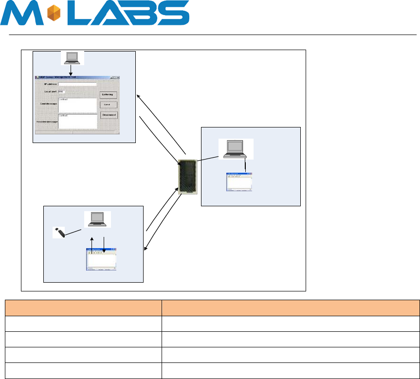
Test Environment Construct
message Test environment
1.usb dongle and PC as message server
2.send message to Apollo
UDP Test environment
1.connect dongle to PC and create dialup as ip server
2. Apollo create IP connection to server
UART Test environment
1.connect Apollo to PC with COM serial cable
2.open Terminal tool and send at command
3.reponse can be shown at terminal window
IP
Server
IP
server
Connect
to
network
Apollo create UDP
connection
with IP
server
IP
Server
Download
firmware
from
server
standard
serial
connection
Send AT
command
Response
shown
at
terminal window
USB
Sent
message
to
Apollo
Response
to SMS
server
AT
command Terminal
UART
Port
Send
AT
command
Response
shown
at
terminal window
SMS
Server
Test Items
Description
Extension Features Test
CDG2/3 Test
Basic Function Test
Field Test
FCC Statement
This equipment has been tested and found to comply with the limits for a Class B digital device,
pursuant to Part 15 of the FCC Rules. These limits are designed to provide reasonable
protection against harmful interference in a residential installation. This equipment generates
uses and can radiate radio frequency energy and, if not installed and used in accordance with
the instructions, may cause harmful interference to radio communications. However, there is
no guarantee that interference will not occur in a particular installation. If this equipment does
cause harmful interference to radio or television reception, which can be determined by turning
the equipment off and on, the user is encouraged to try to correct the interference by one or
more of the following measures:
-- Reorient or relocate the receiving antenna.
-- Increase the separation between the equipment and receiver.
-- Connect the equipment into an outlet on a circuit different from that to which the receiver is
connected.
-- Consult the dealer or an experienced radio/TV technician for help.
This device complies with part 15 of the FCC Rules. Operation is subject to the following two
conditions:
(1) This device may not cause harmful interference, and (2) this device must accept any
interference received, including interference that may cause undesired operation.
Changes or modifications not expressly approved by the party responsible for compliance
could void the user's authority to operate the equipment.
The antenna(s) used for this transmitter must be installed to provide a separation distance of
at least 20 cm from all persons and must not be co-located or operating in conjunction with any
other antenna or transmitter.