MERIT TECHNOLOGY MT-602-1 6 CH 2.4 GHz FHSS RADIO CONTROL SYSTEM User Manual MT 602
SHANGHAI MERIT TECHNOLOGY CORP. 6 CH 2.4 GHz FHSS RADIO CONTROL SYSTEM MT 602
User manual
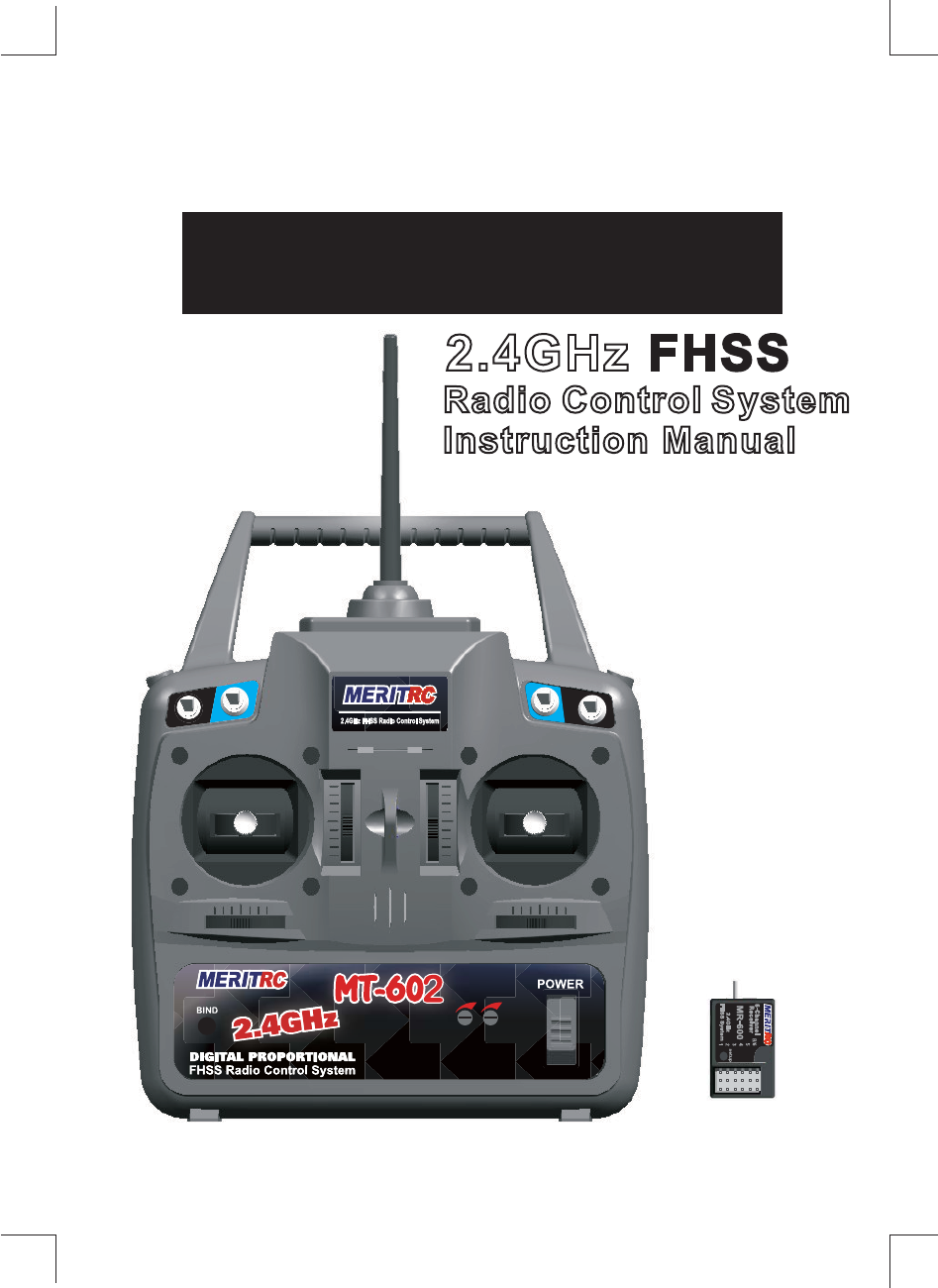
MT-602&MR-600
Radio Control System
Instruction Manual
2.4GHz
CH2 D/R CH6
CH5 CH1 D/R
CH2
D/R
CH1
CH2 D/R CH6
CH5 CH1 D/R
CH2
D/R
CH1
2
CH2 D/R
switch
Elevator(Mode 1)
Throttle(Mode 2)
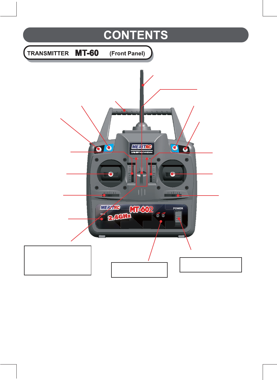
Trim Lever
3-position
switch(CH6) Carrying bar
Antenna
Hook
2-position
switch(CH5)
CH1 D/R switch
Up position D/R-OFF
Down position D/R-ON
Throttle(Mode 1)
Elevator(Mode 2)
Trim lever
Throttle(Mode 1)
Elevator(Mode 2)
/Aileron stick
Elevator(Mode 1)
Throttle(Mode 2)
/Rudder stick
Rudder
Trim Lever
Bind button
LED indicator
Two LED display to
Indicate Batteries Voltage
level,Power Down Mode
and Function Mode CH1&CH2 D/R travel
range adjustment
Power Switch
In the upper position,the
power is turned on.
Aileron
Trim Lever
7KLV VHFWLRQ GHVFULEHV WKH LQVWDOODWLRQ PHWKRG DQG DGMXVWPHQW PHWKRG DIWHU LQVWDOOD
WLRQ ZKHQ LQVWDOOLQJ WKH UHFHLYHU VHUYRV HWF WR WKH SODQH
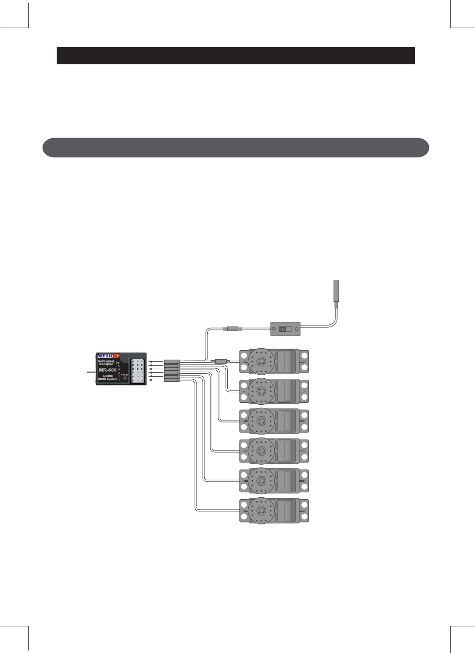
Connections
&RQQHFWLRQ H[DPSOH LV VKRZQ EHORZ
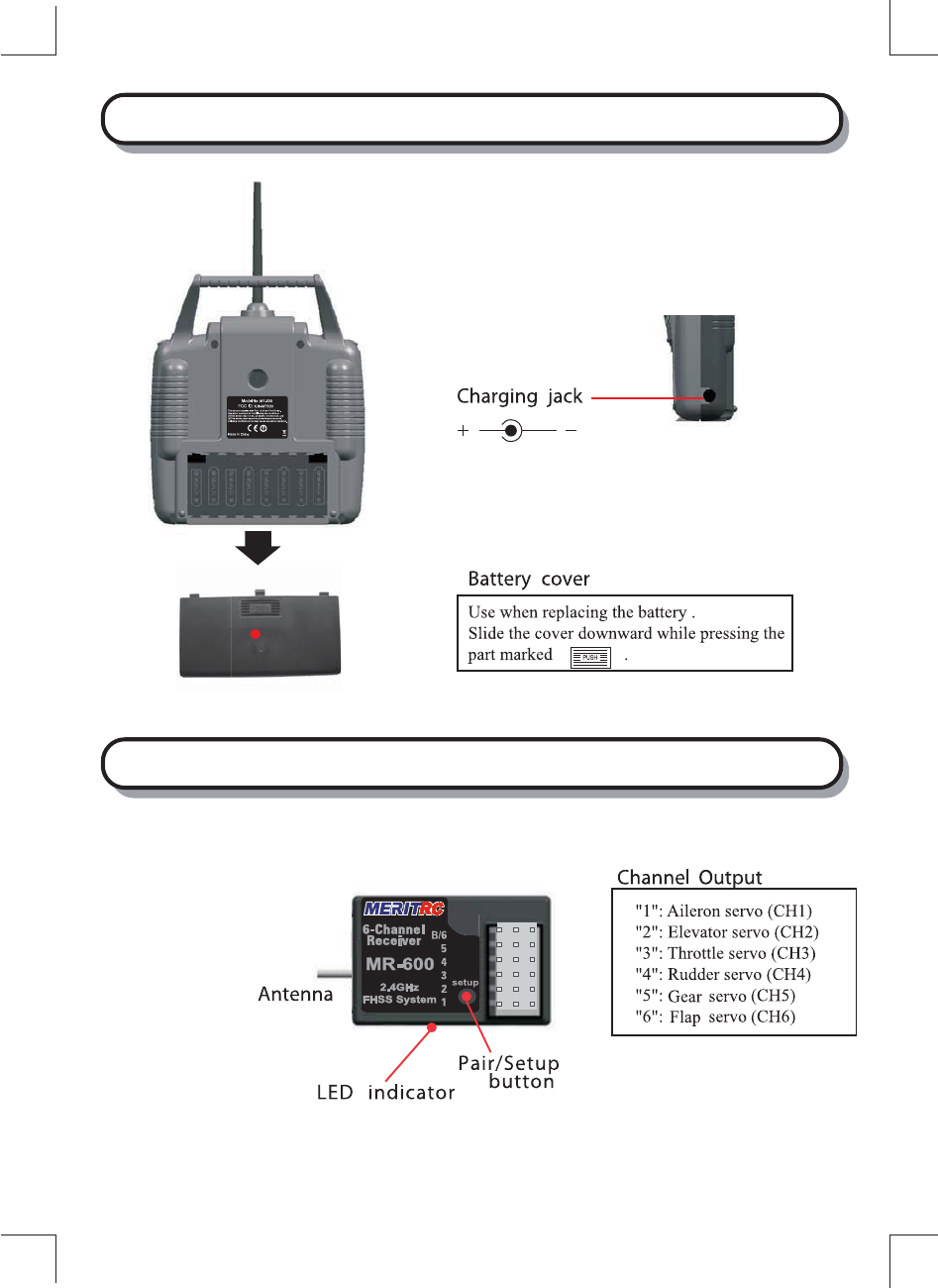
(CH1)
(CH2)
(CH3)
(CH4)
(CH5)
Flap Servo
Gear Servo
Rudder Servo
Throttle Servo
Elevator Servo
Aileron Servo
(CH6)
Receiver
Switch
Harness
To Battery
NOTE:NEVER use dry battery
as it cause malfunction.
(The Y connector is sold separately)
The diagram shown is for aircraft models only.Additional servos may have
to be purchased separately.
ADJUSTMENT AND INSTALLATION
TRANSMITTER MT-602 (Rear and Side Panel)
RECEIVER
MR-600
Special notefor 2.4GHz FHSS radio system setup
Receiver ’s Antenna installation
6LQFH WKH *+] KDYH GLIIHUHQW FKDUDFWHULVWLFV WKDQ WKDW RI WKH FRQYHQWLRQDO IUHTXHQFLHV
SOHDVH UHDG WKLV VHFWLRQ FDUHIXOO\ WR HQMR\ VDIH ÀLJKW ZLWK WKH *+] V\VWHP
7KH ZDYHOHQJWK RI WKH *+] LV PXFK VKRUWHU WKDQ WKDW RI WKH FRQYHQWLRQDO IUHTXHQFLHV
LW LV YHU\ VXVFHSWLEOH WR ORVV RI VLJQDO ZKLFK UHVXOWV LQ D UHFHLYLQJ HUURU
7R REWDLQ WKH EHVW UHVXOWV SOHDVH UHIHU WR WKH IROORZLQJ LQVWUXFWLRQV
7KH DQWHQQD PXVW EH NHSW DV VWUDLJKW DV SRVVLEOH
2WKHUZLVH LW ZLOO UHGXFH WKH HIIHFWLYH UDQJH
7KH DQWHQQD VKRXOG EH
SHUSHQGLFXODUWRWKHIXVHODJH
/DUJHU PRGHOV FDQ KDYH ODUJH PHWDO REMHFWV WKDW FDQ
DWWHQXDWH WKH 5) VLJQDO ,Q WKLV FDVH WKH DQWHQQD VKRXOG
EH SODFHG DW VLGH RI WKH PRGHO 7KHQ WKH EHVW 5)
VLJQDO FRQGLWLRQ LV REWDLQHG DW DQ\ IO\LQJ DWWLWXGH
7KH D
QWHQQD
PXVW EH NHSW DZD\ IURP FRQGXFWLYH PDWHULDOV VXFK DV PHWDO DQG
FDUERQ E\ DW OHDVW D KDOI LQFK 7KH FRD[LDO SDUW RI WKH DQWHQQDV GRHV QRW QHHG WR
IROORZ WKHVH JXLGHOLQHV EXW GR QRW EHQG LW LQ D VPDOO UDGLXV
.HHS WKH DQWHQQD DZD\ IURP WKH PRWRU (6& DQG RWKHU QRLVH VRXUFHV DV PXFK
DV SRVVLEOH
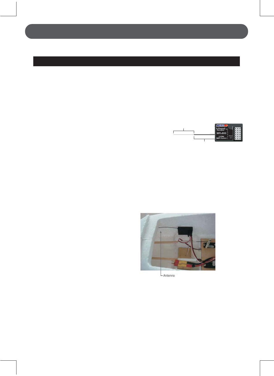
7KH PDLQ SXUSRVH RI WKH SKRWR
GHPRQVWUDWHV KRZ WKH DQWHQQD VKRXOG
EH SODFHG )RU DFWXDO LQVWDOODWLRQ WKH
UHFHLYHU PXVW EH ZUDSSHG ZLWK D
VSRQJH RU SODFHG ZLWK IORDWLQJ PDWHULDO
WR SURWHFW LW IURP YLEUDWLRQ
e
7KH UHFHLYHU FRQWDLQV SUHFLVLRQ HOHFWURQLF SDUWV ,W LV WKH PRVW GHOLFDWH UDGLR
FRPSRQHQW RQERDUG WKH PRGHO DQG VKRXOG EH SURWHFWHG IURP YLEUDWLRQ
VKRFN DQG WHPSHUDWXUH H[WUHPHV 7R SURWHFW WKH UHFHLYHU ZUDS LW LQ 5& IRDP
UXEEHU RU RWKHU YLEUDWLRQDEVRUELQJ PDWHULDO ,I DSSURSULDWH ZDWHUSURRI WKH
UHFHLYHU E\ SODFLQJ LW LQ D SODVWLF EDJ DQG FORVLQJ WKH RSHQ HQG ZLWK D UXEEHU
EDQG EHIRUH ZUDSSLQJ LW LQ IRDP ,I PRLVWXUH HQWHUV WKH UHFHLYHU LQWHUPLWWHQW
RSHUDWLRQ RU D IDLOXUH PD\ UHVXOW :UDSSLQJ WKH UHFHLYHU LQ D SODVWLF EDJ DOVR
SURWHFWV LW IURP IXHO DQG H[KDXVW UHVLGXH ZKLFK LQ VRPH PRGHOV FDQ ZRUN LWV
ZD\ LQWR WKH IXVHODJH
coaxial part

Transmitter antenna
7KH WUDQVPLWWHU DQWHQQD LV DGMXVWDEOH
VR SOHDVH PDNH VXUH WKDW WKH DQWHQQD LV
QHYHU SRLQWHG GLUHFWO\ DW WKH PRGHO
ZKHQ À\LQJ DV WKLV FUHDWHV D ZHDN VLJQDO
IRU WKH UHFHLYHU
.HHS WKH DQWHQQD SHUSHQGLFXODU WR WKH
WUDQVPLWWHUV IDFH WR FUHDWH D EHWWHU 5)
FRQGLWLRQ IRU WKH UHFHLYHU 2I FRXUVH
WKLV GHSHQGV RQ KRZ \RX KROG WKH
WUDQVPLWWHU EXW LQ PRVW FDVHV DGMXVWLQJ
WKH WUDQVPLWWHU DQWHQQD VR WKDW LW LV SHUSHQGLFXODU WR WKH IDFH ZLOO JLYH WKHEHVW
UHVXOWV 3OHDVH DGMXVW WKH WUDQVPLWWHU DQWHQQD WR WKH ZD\ \RX KROG WKH WUDQVPLWWHU
1(9(5 JULS WKH DQWHQQD ZKHQ À\LQJ DV WKLV GHJUDGHV 5) TXDOLW\
FCC Compliance Statement
7KLVHTXLSPHQWKDVEHHQWHVWHGDQGIRXQGWRFRPSO\ZLWKWKHOLPLWVIRUD&ODVV
%GLJLWDOGHYLFHSXUVXDQWWR3DUWRIWKH)&&5XOHV7KHVHOLPLWVDUHGHVLJQHG
WRSURYLGHUHDVRQDEOHSURWHFWLRQDJDLQVWKDUPIXOLQWHUIHUHQFHLQDUHVLGHQWLDO
LQVWDOODWLRQ7KLVHTXLSPHQWJHQHUDWHVXVHVDQGFDQUDGLDWHUDGLRIUHTXHQF\
HQHUJ\DQGLIQRWLQVWDOOHGDQGXVHGLQDFFRUGDQFHZLWKWKHRSHUDWLQJLQVWUXFWLRQV
PD\FDXVHKDUPIXOLQWHUIHUHQFHWRUDGLRFRPPXQLFDWLRQVKRZHYHUWKHUHLVQR
JXDUDQWHHWKDWLQWHUIHUHQFHZLOOQRWRFFXULQDSDUWLFXODULQVWDOODWLRQ,IWKLV
HTXLSPHQWGRHVFDXVHKDUPIXOLQWHUIHUHQFHWRUDGLRRUWHOHYLVLRQUHFHSWLRQZKLFK
FDQEHGHWHUPLQHGE\WXUQLQJWKHHTXLSPHQWRIIDQGRQWKHXVHULVHQFRXUDJHGWR
FRUUHFWWKHLQWHUIHUHQFHE\RQHRUPRUHRIWKHIROORZLQJPHDVXUHV
WARNING
&KDQJHVRUPRGLILFDWLRQVPDGHWRWKLVHTXLSPHQWQRWH[SUHVVO\
DSSURYHGE\WKHSDUW\UHVSRQVLEOHIRUFRPSOLDQFHPD\YRLGWKH)&&DXWKRUL]DWLRQ
WRRSHUDWHWKLVHTXLSPHQW
5)H[SRVXUHVWDWHPHQW
7KLVHTXLSPHQWFRPSOLHVZLWK)&&UDGLDWLRQH[SRVXUHOLPLWVVHWIRUWKIRUDQ
XQFRQWUROOHGHQYLURQPHQW7KHGHYLFHKDVEHHQHYDOXDWHGWRPHHWJHQHUDO5)
H[SRVXUHUHTXLUHPHQW7KHGHYLFHFDQEHXVHGLQSRUWDEOHH[SRVXUHFRQGLWLRQZLWKRXW
UHVWULFWLRQ
The distance close to the finger usually should be 78mm.
7KLVGHYLFHFRPSOLHVZLWKSDUWRIWKH)&&5XOHV2SHUDWLRQLVVXEMHFWWRWKHIROORZLQJ
WZRFRQGLWLRQV7KLVGHYLFHPD\QRWFDXVHKDUPIXOLQWHUIHUHQFHWKLVGHYLFHPXVW
DFFHSWDQ\LQWHUIHUHQFHUHFHLYHGLQFOXGLQJLQWHUIHUHQFHWKDWPD\FDXVHXQGHVLUHG
RSHUDWLRQ
5HRULHQWRUUHORFDWHWKHUHFHLYLQJDQWHQQD
,QFUHDVHWKHVHSDUDWLRQEHWZHHQWKHHTXLSPHQWDQGWKHUHFHLYHU
&RQQHFWWKHHTXLSPHQWLQWRDQRXWOHWRQDFLUFXLWGLIIHUHQWIURPWKDWWRZKLFK
WKHUHFHLYHULVFRQQHFWHG
&RQVXOWWKHGHDOHURUDQH[SHULHQFHGWHFKQLFLDQIRUKHOS

Binding Setup(Pair Procedure)
Fail-Safe Setup
Programming a receiver to recognize the code of only one specific transmitter.
Please note the setup must based on pair procedure well.
1. Turn the power switch on the transmitter & receiver to the ON position,the
LED on transmitter & receiver are continuously lit.
2. Move the stick to the position where you want the servo to move, press and
hold the receiver setup button for 2 second until the red LED on the receiver
flash slowly, then press and hold the receiver setup button again within 5
seconds (Note: after 5 seconds F/S setup will reset, you have to start over
at step one above) until the receiver LED is continuously lit, that's mean the
F/S function has been correctly set.
3.Verify if the failsafe function has been correctly set.Turn off the transmitter,
then check if the servos moves to the position that you set.
4. Any new binding (pair procedure) will clear the preset Fail-Safe.
1. Place the transmitter and the receiver close to each other (within one meter).
Turn the power switch on the transmitter to the ON position.
2. Press and hold the receiver setup button,then turn the power switch to the
ON position. The receiver LED will flash quickly. Release the setup button
after 1 second.
3. Press and hold the binding/PDM button on the transmitter for 1 second until
the green LED on the transmitter flash quickly then the LED on the transmi-
tter and receiver are continuously lit.
If you change transmitters or add a receiver, you must re-bind
before operating your model.
Range check the radio
A range check must be performed before the first flight of a new model.It is not
necessary to do a range check before every flight(but is not a bad idea to per-
form a range check before the first flight of each day).A range check is the final
opportunity to reveal any radio malfunctions,and to be certain the system has
adequate operational range.
1.We have installed a special “Power Down Mode” for doing a ground range
check.To activate the “Power Down Mode” please hold down the Bind key
and then turn the transmitter switch on.During this mode,the RF power is
reduced so the range test can be performed.When this mode is active the
green LED starts blinking.In addition,when the mode is activated the trans-
mitter gives users a warning with a beep sound every 1 seconds,and visual
indication.

The travel Range of the servos for the aileron or elevator can be changed at
any time by using the switch marked CH1 D/R or CH2 D/R,located above
the stick。With the switch in UP position,the channel’s servo will capable
of rotating through its full travel range(100%)。Moving the switch to the opp-
-osite position(DOWN) will limit the rotational range of the channel’s servo。
To adjust the D/R setting:
1.Swith the D/R switch to the DOWN position。
2.Adjust the trimmer located on the panel marked D/R CH1 or CH2,When
the trimmer is turned counter-clockwise,the rotational range will decreases
(Minimum 30%),conversely,the trimmer is turned clockwise,the rotational
range will increases(Maximum 100%)。
CH1,CH2 DUAL RATE (D/R)
2.Walk away from the model while simultaneously operating the controls.Have
an assistant stand by the model and signal what the controls are doing to
confirm that they operate correctly.You should be able to walk approximately
30 - 50 paces from the model without losing control.
3.If everything operates correctly,return to the model.Set the transmitter in a
safe,yet accessible location so it will be within reach after starting the engine.
Be certain the throttle stick is all the way down,then start the engine.Perform
another range check with your assistant holding the plane and the engine
running at various speeds.If the servos jitter or move inadvertently,there may
be a problem.Do not fly the plane!Look for loose servo connections or binding
pushrods.Also be certain that the battery has been fully charged.
4.The “Power Down Mode” continues for 60 seconds and after that the power
will go back to the normal level.
To exit the “Power Down Mode” before the 60 seconds,turn the transmitter
switch on again.
5.NEVER start flying when the “Power Down Mode” is active.

The Elevon and V-tail mixing functions which can be turned on or off 。Ele-
-von control consists of a mixture between the elevator and aileron channels。
V-tail control consists of mixture between the elevator and rudder channels。
The default setting for all mixing will be off the GREEN LED should be on
steady。
To change the mix setting:
1.Switch off the TX power switch。
2.Press and hold CH2 and CH3 DOWN&HIGH trim button simultaneously。
3.Switch the TX power switch on,the GREEN LED should flash constantly
to indicate the mixing function has been turned on。
4.Repeat steps 1-3 to change the mixing function form Elevon on 、V-tail on
then off in sequence。
ELEVON & V-TAIL MIXING FUNCTIONS
This function changes the stick mode of transmitter。
Note:This will not change the throttle Ratchet etc。Those are mechanical
changes that must be performed by specific technician。
To change the MODE setting:
1.Switch off the TX power switch。
2.Press and hold CH1 and CH4 LEFT&RIGHT trim button simultaneously。
3.Switch the TX power switch on,the GREEN LED should flash and acco-
-mpanied by two audible tones indicate the MODE 2 function has been tur-
-ned on。Conversely the GREEN LED flash and accompanied by one audi-
-ble tone indicate the MODE 1 function has been turned on。
4.Repeat steps 1-3 to change the MODE function form MODE1 to MODE 2
in sequence。
5.Since TX power switch on then accompanied by one audible tone indicate
the MODE 1 function has been turned on,if accompanied by two audible
tones indicate the MODE 2 function has been turned on。
MODE 1、MODE 2 STICK SETTING
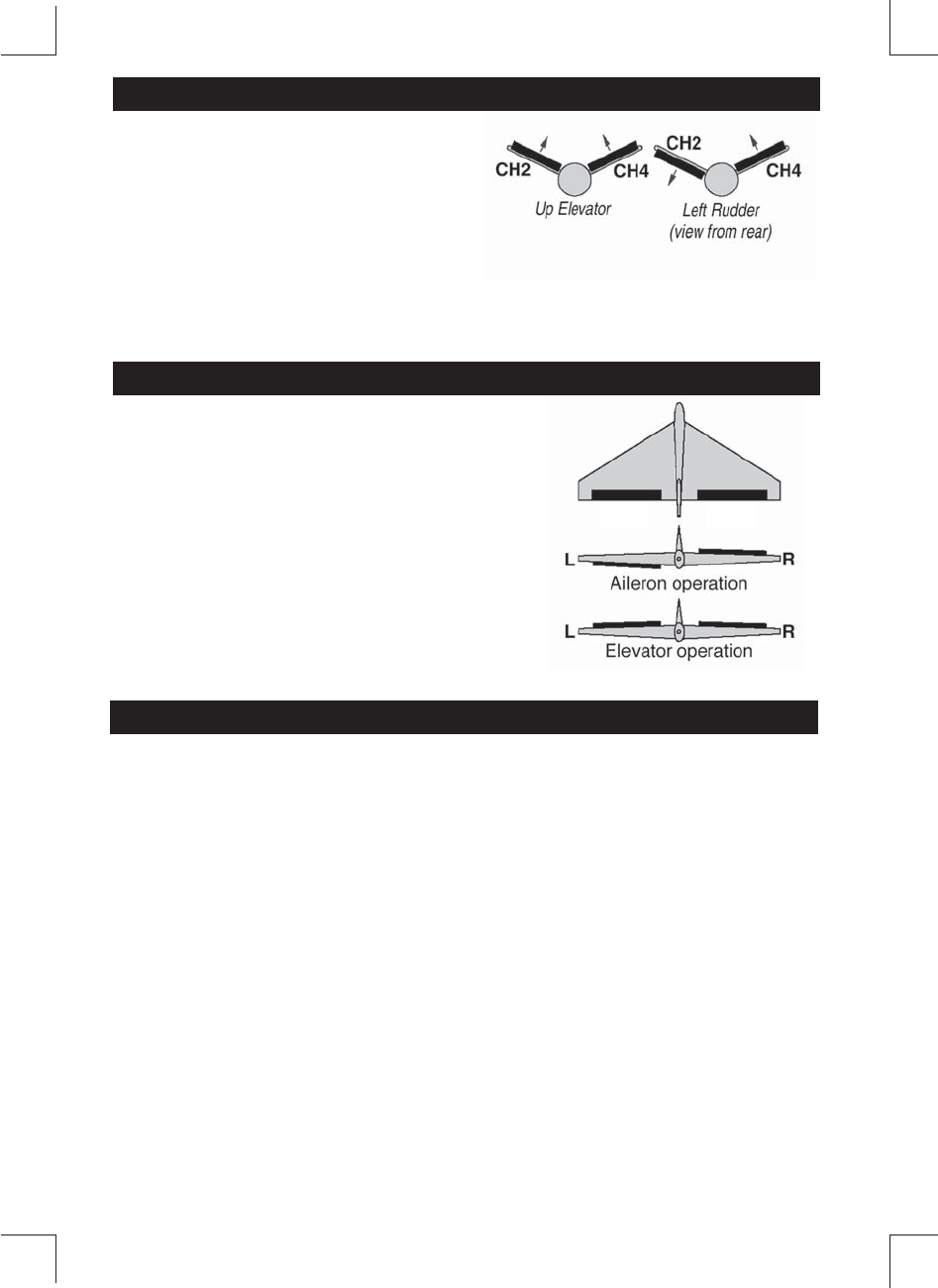
Intended for V-tail aircaft,V-tail mixing
allows the ruddervators to operate both
as rudders and elevators.The same as
the other mixes,V-tail mixing requires
that each ruddervator be operated by a
separate servo.
*If necessary,use the Servo Reversing
function to achieve the correct direction
of servo throws.
*If necessary,use the Servo Reversing
function to achieve the correct direction
of servo throws.
V-tail Mixing
Intended for tailless,“flying wing” models such
as delta wings and flying wings,elevon mixing
mixes channel 1 (aileron) to channel 2 (eleva
tor) allowing the elevons to operate in unison
(as elevators) or in opposition (as ailerons).
This function requires that each elevon be
operated by a separate servo.
Delta Wing Mixing
CH1 CH2
The direction of movement for any of the four channels can be reversed elec
tronically。
To change the direction of movement for each main channel:
1.Switch off the TX power switch。
2.Press and hold one specific trim button for the channel to be reversed。
CH1 right trim button for CH1 reversing.
CH2 down trim button for CH2 reversing.
CH3 high trim button for CH3 reversing.
CH4 right trim button for CH4 reversing.
3.Switch the TX power switch on,the GREEN LED should flash then steady
on to indicate the movement for that channel has been reversed。
4.Repeat steps 1-3 to reverse the direction of any other channel as needed。
SERVO REVERSING
Transmitter Operation and Movement of Each Servo
%HIRUH PDNLQJ DQ\ DGMXVWPHQWV OHDUQ WKH RSHUDWLRQ RI WKH WUDQVPLWWHU DQG WKH
PRYHPHQW RI HDFK VHUYR ,Q WKH IROORZLQJ GHVFULSWLRQV WKH WUDQVPLWWHU LV DVVXPHG
WR EH LQ WKH VWDQGE\ VWDWH
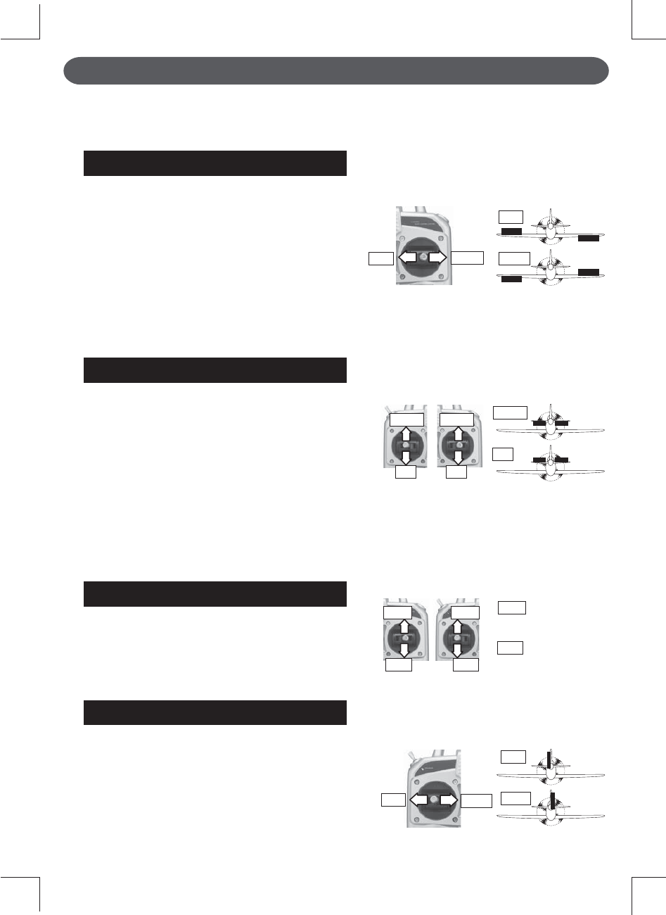
AILERON OPERATION
:KHQ WKH DLOHURQ VWLFN LV PRYHG WR WKH
ULJKW WKH ULJKW DLOHURQ LV UDLVHG DQG WKH OHIW
DLOHURQ LV ORZHUHG UHODWLYH WR WKH GLUHFWLRQ
RI IOLJKW DQG WKH SODQH WXUQV WR WKH ULJKW
:KHQ WKH DLOHURQ VWLFN LV PRYHG WR WKH OHIW
WKH DLOHURQV PRYH LQ WKH RSSRVLWH GLUHFWLRQ
7R OHYHO WKH SODQH WKH DLOHURQ VWLFN PXVW
EH PRYHG LQ WKH RSSRVLWH GLUHFWLRQ
:KHQ WKH DLOHURQ VWLFN LV WLOWHG DQG KHOG
WKH SODQH ZLOO UROO
ELEVATOR OPERATION
:KHQ WKH HOHYDWRU VWLFN LV SXOOHG EDFN WKH
WDLO HOHYDWRU LV UDLVHG DQG WKH WDLO RI WKH
SODQH LV IRUFHG GRZQ WKH DLU IORZ DSSOLHG
WR WKH ZLQJV LV FKDQJHG WKH OLIWLQJ IRUFH LV
LQFUHDVHG DQG WKH SODQH FOLPEV 83 RSHUD
WLRQ :KHQ WKH HOHYDWRU VWLFN LV SXVKHG
IRUZDUG WKH HOHYDWRU LV ORZHUHG WKH WDLO RI
WKH SODQH LV IRUFHG XS WKH DLU IORZ DSSOLHG
WR WKH ZLQJV LV FKDQJHG WKH OLIWLQJ IRUFH LV
GHFUHDVHG DQG WKH SODQH GLYHV '2:1
RSHUDWLRQ
THROTTLE OPERATION
:KHQ WKH WKURWWOH VWLFN LV SXOOHG EDFN WKH
HQJLQH WKURWWOH OHYHU DUP PRYHV WR WKH
6/2: ORZ VSHHG VLGH :KHQ WKH WKURWWOH
VWLFN LV SXVKHG IRUZDUG WKH WKURWWOH OHYHU
DUP PRYHV WR WKH +,*+ KLJK VSHHG VLGH
RUDDER OPERATION
:KHQ WKH UXGGHU VWLFN LV PRYHG WR WKH
ULJKW WKH UXGGHU PRYHV WR WKH ULJKW DQG WKH
QRVH SRLQWV WR WKH ULJKW UHODWLYH WR WKH
GLUHFWLRQ RI IOLJKW :KHQ WKH UXGGHU VWLFN LV
PRYHG WR WKH OHIW WKH UXGGHU PRYHV WR WKH
OHIW DQG WKH QRVH SRLQWV WR WKH OHIW DQG WKH
GLUHFWLRQ RI WUDYHO RI WKH SODQH FKDQJHV
Elevator(CH2)
Aileron(CH1)
Throttle(CH3)
Rudder(CH4)
Right
9LHZHG IURP WKH UHDU
WR WKH KLJK VSHHG VLGH
(QJLQH WKURWWOH OHYHU PRYHV
WR WKH ORZ VSHHG VLGH
Left Right
Down
(Mode 1) (Mode 2)
Up
High
Low
(Mode 1) (Mode 2)
Left
Left Light
Right
Down Down
Up Up
High High
Low Low
Left
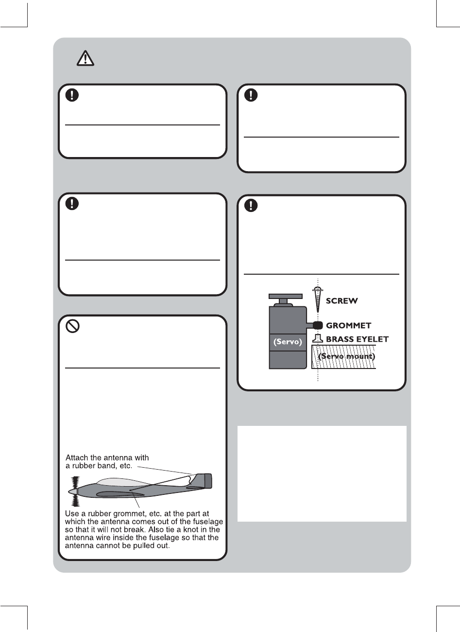
WARNING
Connector Connection
,QVHUW WKH UHFHLYHU VHUYR DQG
EDWWHU\ FRQQHFWRUV IXOO\ DQG
ILUPO\
,I YLEUDWLRQ HWF FDXVHV D FRQQHFWRU WR
ZRUN ORRVH GXULQJ IOLJKW WKH SODQH PD\
FUDVK
Receiver Vi brationpr oong
/ Waterpr oong
9LEUDWLRQSURRI WKH UHFHLYHU E\
ZUDSSLQJ LW LQ VSRQJH UXEEHU RU
VRPH VXFK PDWHULDO ,I WKH UH
FHLYHU PD\ JHW ZHW ZDWHUSURRI
LW E\ SODFLQJ LW LQ D SODVWLF EDJ
,I WKH UHFHLYHU LV VXEMHFWHG WR VWURQJ YLEUD
WLRQ DQG VKRFN RU JHWV ZHW LW PD\ RSHUDWH
HUURQHRXVO\ DQG FDXVH D FUDVK
Receiver Antenna
'R QRW FXW RU EXQGOH WKH UH
FHLYHU DQWHQQD $OVR GR QRW
EXQGOH WKH DQWHQQD WRJHWKHU
ZLWK WKH VHUYR OHDG ZLUHV
&XWWLQJ RU EXQGOLQJ WKH UHFHLYHU DQWHQQD
ZLOO ORZHU WKH UHFHLYHU VHQVLWLYLW\ DQG
VKRUWHQ WKH IOLJKW UDQJH DQG FDXVH D FUDVK
<Antenna installation>
)RU DLUFUDIW DWWDFK WKH DQWHQQD WR WKH WRS RI
WKH WDLO
Servo Thr ow
2SHUDWH HDFK VHUYR KRUQ RYHU
LWV IXOO VWURNH DQG DGMXVW VR WKDW
WKH SXVKURG GRHV QRW ELQG RU LV
QRW WRR ORRVH
8QUHDVRQDEOH IRUFH DSSOLHG WR WKH VHUYR
KRUQ ZLOO DGYHUVHO\ DIIHFW WKH VHUYR DQG
GUDLQ WKH EDWWHU\ TXLFNO\
Servo Installation
,QVWDOO WKH VHUYRV WR WKH VHUYR
PRXQW HWF WKURXJK D UXEEHU
JURPPHW $OVR LQVWDOO WKH VHUYRV
VR WKDW WKH VHUYR FDVH GRHV QRW
GLUHFWO\ WRXFK WKH VHUYR PRXQW
RU RWKHU SDUWV RI WKH IXVHODJH
Power Switch Installation
:KHQ LQVWDOOLQJ D UHFHLYHU SRZHU VZLWFK WR WKH
IXVHODJH FXW D UHFWDQJXODU KROH VRPHZKDW
ODUJHU WKDQ WKH IXOO VWURNH RI WKH VZLWFK NQRE
DQG LQVWDOO WKH VZLWFK VR LW PRYHV VPRRWKO\
IURP 21 WR 2))
$OVR LQVWDOO WKH VZLWFK ZKHUH LW ZLOO QRW FRPH
LQWR GLUHFW FRQWDFW ZLWK HQJLQH RLO GXVW HWF
*HQHUDOO\ LQVWDOO WKH VZLWFK WR WKH IXVHODJH DW
WKH VLGH RSSRVLWH WKH PXIIOHU H[KDXVW