MMB Research BSB03PA1X EFR32 802.15.4 Module User Manual
MMB Research Inc. EFR32 802.15.4 Module Users Manual
UserManual.wiki
>
MMB Research
>
BSB03PA1X User Manual
Users Manual
Navigation menu
Upload a User Manual
Namespaces
Wiki Guide
HTML
PDF
Info
Views
User Manual
Discussion / Help
Navigation
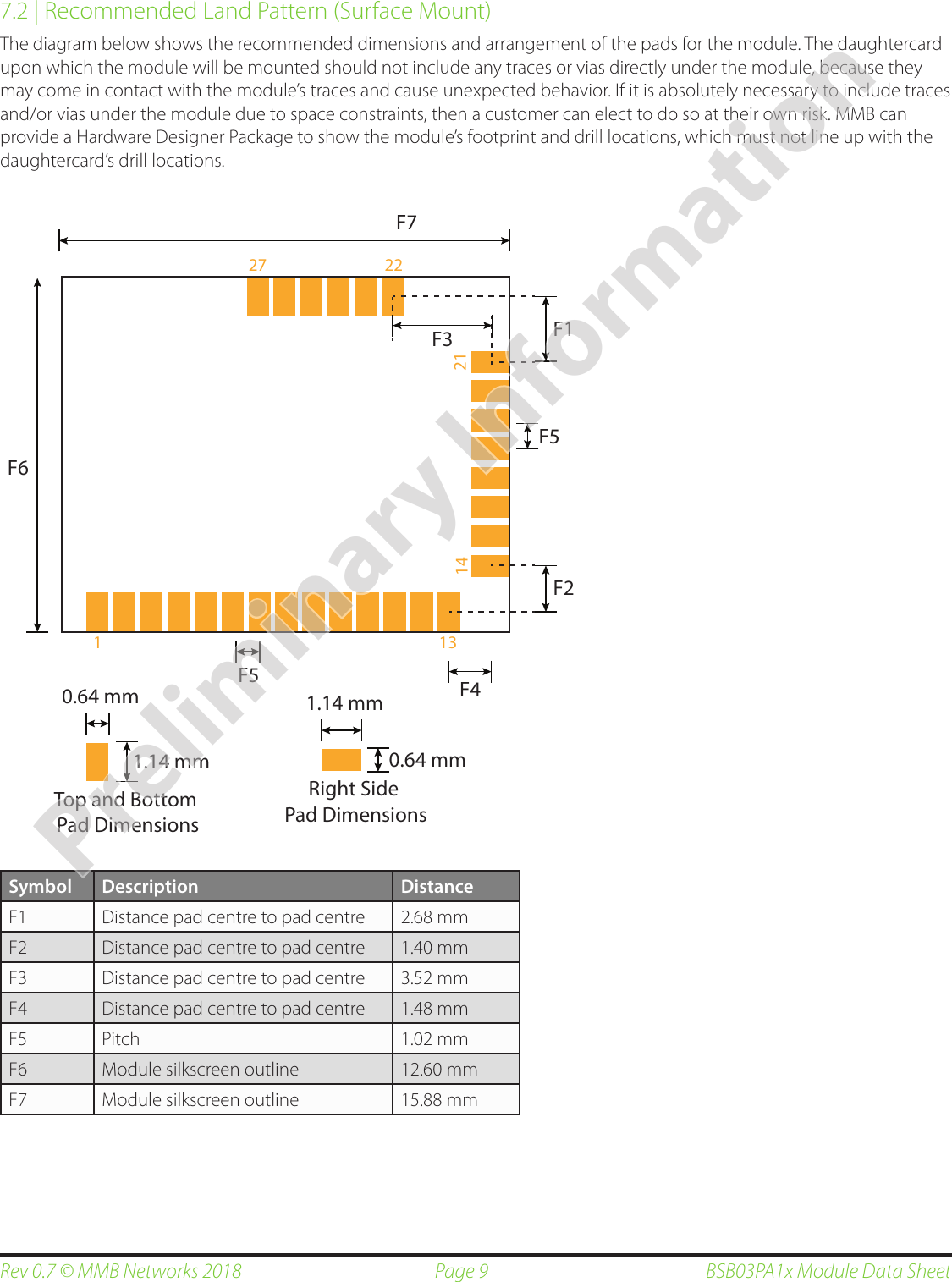
![Page 11Rev 0.7 © MMB Networks 2018 BSB03PA1x Module Data Sheet8 | Soldering Temperature Time Prole for reow soldering (Lead-free solder)150˚C - 190˚C220˚C30 +20/-10s90 ±30s230˚C - 240˚C maxTemp[ ˚C ]Time [ s ]Maximum reflow cycles: 2Opposite-side reflow is prohibited due to the module weight. You must not place the module on the bottom / underside of your PCB and re-flow.9 | Regulatory Approvals9.1 | Federal Communications Commission (FCC - US)Note: this section applies to BSB03PA1x-CHP and BSB03PA1x-RFC devices only.9.1.1 | Approved AntennaeFor the BSB03PA1x-CHP modules using the onboard chip antenna, the approved power level settings are -2 dBm for channels 11-25 and -20 dBm for channel 26. The onboard chip antenna is Inpaq ACA-2012-A1-CC-S.For the BSB03PA1x-RFC modules using the approved external antenna, the approved power level settings are -11 dBm for channels 11-25 and -26 dBm for channel 26. The BSB03PA1x-RFC devices have been approved with the following external FCC approved antennas: Mag Layers EDA-1713-2G4C1-A2, and Bondale G-RA0K13200284-SZ478.9.1.2 | FCC NoticeThe BSB03PA1x-CHP and BSB03PA1x-RFC devices comply with Part 15 of the FCC rules. Operation is subject to the following two conditions: (1) This device may not cause harmful interference, and (2) This device must accept any interference received, including interference that may cause undesired operation. To comply with FCC RF Exposure requirements, users of this device must ensure that the module be installed and/or configured to operate with a separation distance of 20cm or more from all persons. Usage of Channel 26 at full power will result in non-compliance to FCC standards. MMB recommends avoiding use of channel 26 and if necessary only use with a reduced power setting. For further details please contact MMB.Preliminary Information](https://usermanual.wiki/MMB-Research/BSB03PA1X/User-Guide-3752799-Page-11.png)