MOJIX CBLENODE3K Star 3000 System User Manual USERMANUAL STAR3000 2 0 1x

MOJIX, Inc. Star 3000 System USERMANUAL STAR3000 2 0 1x

Users Manual Part 2

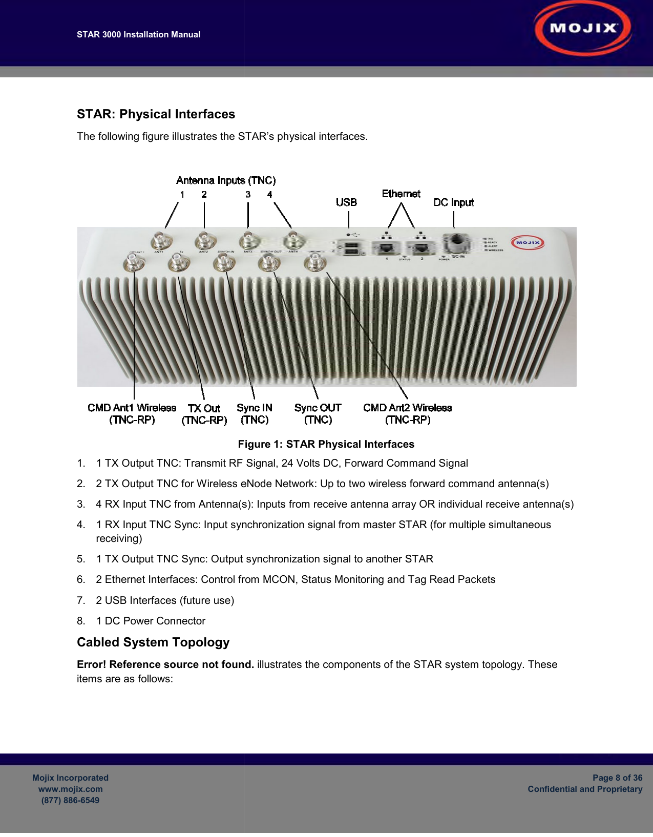
STAR 3000 Installation Manual       Mojix Incorporated www.mojix.com (877) 886-6549    STAR: Physical Interfaces The following figure illustrates the STAR’s physical interfaces. Figure 1.  1 TX Output TNC: Transmit RF Signal, 24 Volts DC, Forward Command Signal2.  2 TX Output TNC for Wireless eNode Network3. 4 RX Input TNC from Antenna(s)4.  1 RX Input TNC Sync: Input synchronization signal from master STAR (for multiple receiving) 5.  1 TX Output TNC Sync: Output synchronization signal to another STAR6.  2 Ethernet Interfaces: Control from MCON7.  2 USB Interfaces (future use) 8.  1 DC Power Connector Cabled System Topology Error! Reference source not found.items are as follows:      illustrates the STAR’s physical interfaces. Figure 1: STAR Physical Interfaces Transmit RF Signal, 24 Volts DC, Forward Command Signal for Wireless eNode Network: Up to two wireless forward command antenna(s)4 RX Input TNC from Antenna(s): Inputs from receive antenna array OR individual receive antenna(s)Input synchronization signal from master STAR (for multiple Output synchronization signal to another STAR Control from MCON, Status Monitoring and Tag Read Packetsource not found. illustrates the components of the STAR system topologyPage 8 of 36 Confidential and Proprietary  Up to two wireless forward command antenna(s) Inputs from receive antenna array OR individual receive antenna(s) Input synchronization signal from master STAR (for multiple simultaneous Tag Read Packets system topology. These

Navigation menu